US9913596B2 - Systems and methods for MRI guided trans-orifice and transperineal intervention apparatus with adjustable biopsy needle insertion - Google Patents
Systems and methods for MRI guided trans-orifice and transperineal intervention apparatus with adjustable biopsy needle insertion Download PDFInfo
- Publication number
- US9913596B2 US9913596B2 US13/304,573 US201113304573A US9913596B2 US 9913596 B2 US9913596 B2 US 9913596B2 US 201113304573 A US201113304573 A US 201113304573A US 9913596 B2 US9913596 B2 US 9913596B2
- Authority
- US
- United States
- Prior art keywords
- adjustment mechanism
- orifice
- intervention tool
- patient
- securement
- Prior art date
- Legal status (The legal status is an assumption and is not a legal conclusion. Google has not performed a legal analysis and makes no representation as to the accuracy of the status listed.)
- Active, expires
Links
Images


Classifications
-
- A—HUMAN NECESSITIES
- A61—MEDICAL OR VETERINARY SCIENCE; HYGIENE
- A61B—DIAGNOSIS; SURGERY; IDENTIFICATION
- A61B5/00—Measuring for diagnostic purposes; Identification of persons
- A61B5/05—Detecting, measuring or recording for diagnosis by means of electric currents or magnetic fields; Measuring using microwaves or radio waves
- A61B5/055—Detecting, measuring or recording for diagnosis by means of electric currents or magnetic fields; Measuring using microwaves or radio waves involving electronic [EMR] or nuclear [NMR] magnetic resonance, e.g. magnetic resonance imaging
-
- A—HUMAN NECESSITIES
- A61—MEDICAL OR VETERINARY SCIENCE; HYGIENE
- A61B—DIAGNOSIS; SURGERY; IDENTIFICATION
- A61B5/00—Measuring for diagnostic purposes; Identification of persons
- A61B5/68—Arrangements of detecting, measuring or recording means, e.g. sensors, in relation to patient
- A61B5/6846—Arrangements of detecting, measuring or recording means, e.g. sensors, in relation to patient specially adapted to be brought in contact with an internal body part, i.e. invasive
- A61B5/6847—Arrangements of detecting, measuring or recording means, e.g. sensors, in relation to patient specially adapted to be brought in contact with an internal body part, i.e. invasive mounted on an invasive device
-
- G—PHYSICS
- G01—MEASURING; TESTING
- G01R—MEASURING ELECTRIC VARIABLES; MEASURING MAGNETIC VARIABLES
- G01R33/00—Arrangements or instruments for measuring magnetic variables
- G01R33/20—Arrangements or instruments for measuring magnetic variables involving magnetic resonance
- G01R33/28—Details of apparatus provided for in groups G01R33/44 - G01R33/64
- G01R33/285—Invasive instruments, e.g. catheters or biopsy needles, specially adapted for tracking, guiding or visualization by NMR
- G01R33/287—Invasive instruments, e.g. catheters or biopsy needles, specially adapted for tracking, guiding or visualization by NMR involving active visualization of interventional instruments, e.g. using active tracking RF coils or coils for intentionally creating magnetic field inhomogeneities
-
- G—PHYSICS
- G01—MEASURING; TESTING
- G01R—MEASURING ELECTRIC VARIABLES; MEASURING MAGNETIC VARIABLES
- G01R33/00—Arrangements or instruments for measuring magnetic variables
- G01R33/20—Arrangements or instruments for measuring magnetic variables involving magnetic resonance
- G01R33/28—Details of apparatus provided for in groups G01R33/44 - G01R33/64
- G01R33/32—Excitation or detection systems, e.g. using radio frequency signals
- G01R33/34—Constructional details, e.g. resonators, specially adapted to MR
- G01R33/34084—Constructional details, e.g. resonators, specially adapted to MR implantable coils or coils being geometrically adaptable to the sample, e.g. flexible coils or coils comprising mutually movable parts
-
- A—HUMAN NECESSITIES
- A61—MEDICAL OR VETERINARY SCIENCE; HYGIENE
- A61B—DIAGNOSIS; SURGERY; IDENTIFICATION
- A61B17/00—Surgical instruments, devices or methods, e.g. tourniquets
- A61B17/00234—Surgical instruments, devices or methods, e.g. tourniquets for minimally invasive surgery
- A61B2017/00238—Type of minimally invasive operation
- A61B2017/00274—Prostate operation, e.g. prostatectomy, turp, bhp treatment
-
- A—HUMAN NECESSITIES
- A61—MEDICAL OR VETERINARY SCIENCE; HYGIENE
- A61B—DIAGNOSIS; SURGERY; IDENTIFICATION
- A61B17/00—Surgical instruments, devices or methods, e.g. tourniquets
- A61B17/34—Trocars; Puncturing needles
- A61B17/3403—Needle locating or guiding means
- A61B2017/3405—Needle locating or guiding means using mechanical guide means
- A61B2017/3411—Needle locating or guiding means using mechanical guide means with a plurality of holes, e.g. holes in matrix arrangement
-
- A—HUMAN NECESSITIES
- A61—MEDICAL OR VETERINARY SCIENCE; HYGIENE
- A61B—DIAGNOSIS; SURGERY; IDENTIFICATION
- A61B17/00—Surgical instruments, devices or methods, e.g. tourniquets
- A61B17/34—Trocars; Puncturing needles
- A61B17/3403—Needle locating or guiding means
- A61B2017/3413—Needle locating or guiding means guided by ultrasound
-
- A—HUMAN NECESSITIES
- A61—MEDICAL OR VETERINARY SCIENCE; HYGIENE
- A61B—DIAGNOSIS; SURGERY; IDENTIFICATION
- A61B18/00—Surgical instruments, devices or methods for transferring non-mechanical forms of energy to or from the body
- A61B2018/00315—Surgical instruments, devices or methods for transferring non-mechanical forms of energy to or from the body for treatment of particular body parts
- A61B2018/00547—Prostate
-
- A—HUMAN NECESSITIES
- A61—MEDICAL OR VETERINARY SCIENCE; HYGIENE
- A61B—DIAGNOSIS; SURGERY; IDENTIFICATION
- A61B90/00—Instruments, implements or accessories specially adapted for surgery or diagnosis and not covered by any of the groups A61B1/00 - A61B50/00, e.g. for luxation treatment or for protecting wound edges
- A61B90/36—Image-producing devices or illumination devices not otherwise provided for
- A61B90/37—Surgical systems with images on a monitor during operation
- A61B2090/374—NMR or MRI
-
- A—HUMAN NECESSITIES
- A61—MEDICAL OR VETERINARY SCIENCE; HYGIENE
- A61B—DIAGNOSIS; SURGERY; IDENTIFICATION
- A61B8/00—Diagnosis using ultrasonic, sonic or infrasonic waves
- A61B8/12—Diagnosis using ultrasonic, sonic or infrasonic waves in body cavities or body tracts, e.g. by using catheters
-
- G—PHYSICS
- G01—MEASURING; TESTING
- G01R—MEASURING ELECTRIC VARIABLES; MEASURING MAGNETIC VARIABLES
- G01R33/00—Arrangements or instruments for measuring magnetic variables
- G01R33/20—Arrangements or instruments for measuring magnetic variables involving magnetic resonance
- G01R33/28—Details of apparatus provided for in groups G01R33/44 - G01R33/64
- G01R33/285—Invasive instruments, e.g. catheters or biopsy needles, specially adapted for tracking, guiding or visualization by NMR
- G01R33/286—Invasive instruments, e.g. catheters or biopsy needles, specially adapted for tracking, guiding or visualization by NMR involving passive visualization of interventional instruments, i.e. making the instrument visible as part of the normal MR process
Definitions
- This invention relates to a trans-orifice and transperineal guidance and imaging apparatus for directing interventional devices into tissue.
- an intervention apparatus comprising a probe having an orifice insertion portion, the insertion portion being configured for insertion into an orifice of a patient; and an intervention tool securement and adjustment mechanism removably attached to the probe, the probe providing support to hold the mechanism in a position relative to the patient, and the adjustment mechanism providing adjustment of an entry point and an angle of entry for an intervention tool to the patient.
- the insertion portion may include an imaging coil, or multiple imaging coils, configured for use with magnetic resonance imaging (MRI) of a tissue of interest in the patient.
- MRI magnetic resonance imaging
- the MRI of the tissue of interest may provide guidance of the intervention tool to the tissue of interest.
- the intervention tool securement and adjustment mechanism may comprise an angle adjustment mechanism operable to adjust the angle of insertion of the interventional tool to the tissue of interest.
- the angle adjustment mechanism may include a locking mechanism to maintain the angle of insertion of the interventional tool.
- the orifice insertion portion of the probe may have a channel therethrough and may have a longitudinal axis.
- the angle adjustment mechanism may direct the interventional tool through the channel towards the tissue of interest.
- the apparatus may further comprise a rotational adjustment mechanism removably attached to the probe and operable to rotate the probe around the longitudinal axis, whereby the angle adjustment mechanism is also rotated around the longitudinal axis.
- the intervention tool securement and adjustment mechanism, the rotation adjustment mechanism and the channel of the orifice insertion portion may be configured so that, when the orifice insertion portion of the probe is inserted through the anus of the patient and positioned in the rectum, the intervention tool may be delivered through the channel inter-orifice through the wall of the rectum to the tissue of interest.
- the probe may further comprise a neck portion to which the intervention tool securement and adjustment mechanism and the rotation adjustment mechanism may be removably attached.
- the orifice insertion portion and the neck portion may be substantially cylindrical.
- the neck portion may have a smaller diameter than the orifice insertion portion.
- the intervention tool securement and adjustment mechanism may include an intervention tool locking mechanism thereon, to secure the intervention tool in a desired position.
- the intervention tool securement and adjustment mechanism may be configured so that, when the orifice insertion portion of the probe is inserted through the anus of the patient, the intervention tool may be delivered transperineally to the tissue of interest.
- the intervention tool securement and adjustment mechanism may further comprise a second imaging coil, or multiple coils, configured for use with MRI of the tissue of interest in the patient.
- the intervention tool locking mechanism may comprise a hole passing through a first plate, a second plate and an elastomer plate between the first and second plates, for accepting the intervention tool therethrough; a compressing mechanism configured to act on the first and second plates to compress the elastomer plate, whereby upon compression of the elastomer plate, the elastomer expands at least in a direction perpendicular to the compression, decreasing the diameter of the hole at the elastomer plate to secure the intervention tool passing therethrough.
- the angle adjustment mechanism may be removably attached to the intervention tool securement and adjustment mechanism.
- a method for imaging and performing intervention on a tissue of interest in a patient comprising: inserting a magnetic resonance imaging (MRI) coil housed within a probe through the anus of the patient; obtaining MRI information associated with the tissue of interest through the MRI coil; and using the MRI information, guiding an intervention tool to the tissue of interest through an intervention tool securement and adjustment mechanism removably attached to the probe.
- the intervention tool may pass through the portion of the probe inserted through the anus of the patient, whereby the intervention tool passes through the wall of the rectum towards the tissue of interest.
- the intervention tool may pass transperineally into the patient towards the tissue of interest.
- the intervention tool securement and adjustment mechanism may further comprise a second MRI coil, which can tend to increase the quality of the images of the region of interest that can be obtained, and/or provide additional associated with the tissue of interest, for use in guiding the intervention tool to the tissue of interest, or diagnosis.
- FIGS. 1A and 1B show isometric views of an embodiment of an intervention tool securement and adjustment mechanism
- FIGS. 2A to 2G show embodiments of an angle adjustment mechanism for the guidance system
- FIG. 3A shows isometric views of a rotational adjustment mechanism
- FIG. 3B shows additional views of the rotational adjustment mechanism shown in FIG. 3A ;
- FIGS. 4A to 4D show isometric views of an embodiment of a rotation locking mechanism of the rotational adjustment mechanism shown in FIGS. 3A and 3B ;
- FIG. 5A shows an isometric view of an embodiment of an angle locking mechanism for the angle adjustment mechanism shown in FIGS. 2A-2E ;
- FIGS. 5B to 5E show alternate locking mechanisms for angle adjustment
- FIG. 6A shows an isometric view of an embodiment of a needle lock slide for the angle adjustment mechanism shown in FIGS. 2A-2E ;
- FIG. 6B shows a side view of the needle lock slide shown in FIG. 6A ;
- FIG. 7A shows an isometric view of an alternate embodiment of a needle lock screw for the angle adjustment mechanism shown in FIGS. 2A-2E ;
- FIG. 7B shows a side view of the needle lock screw shown in FIG. 7A ;
- FIG. 8A show a surface view of an embodiment of a trans-orifice apparatus
- FIG. 8B shows subsurface views of the trans-orifice guidance apparatus shown in FIG. 8A ;
- FIG. 8C shows surface views of embodiments of a trans-orifice apparatus
- FIG. 9 shows an isometric subsurface view of an embodiment of an imaging component of a trans-orifice guidance apparatus, having a fiducial marker
- FIG. 10 shows an isometric view of another embodiment of an intervention tool securement and adjustment mechanism
- FIGS. 11A and 11B show views of embodiments of a needle locking system
- FIGS. 12A and 12B show isometric views of an embodiment of a needle locking system
- FIG. 13A shows an isometric view of an embodiment of an intervention tool securement and adjustment mechanism including magnetic resonance Imaging single loop coils
- FIGS. 13B and 13C show embodiments of intervention tool securement and adjustment mechanisms including magnetic resonance imaging single loop butterfly coils
- FIG. 13D shows an isometric view of an embodiment of an intervention tool securement and adjustment mechanism including fiducial marker for imaging purposes
- FIG. 14A shows a label system to identify specific needle holes in an intervention tool securement and adjustment mechanism
- FIGS. 14B and 14C show a template to identify specific needle holes in an intervention tool securement and adjustment mechanism
- FIG. 14D shows an isometric view of an LED grid to identify specific needle holes in transperineal intervention guidance system
- FIG. 15A shows an embodiment of an intervention tool securement and adjustment mechanism with an angle template system
- FIG. 15B shows an isometric view of a frame to adjust needle angles in the intervention tool securement and adjustment mechanism shown in FIG. 15A ;
- FIGS. 15C and 15D show views of an angle plug to adjust needle angles in the intervention tool securement and adjustment mechanism shown in FIGS. 15A and 15B ;
- FIG. 16 shows alternate embodiments of guidance system.
- Prostate, cervical and colorectal diseases represent significant health problems in the United States; metastatic prostate cancer is the third leading cause of death among American men over fifty years, and currently resulting in approximately 31,000 deaths annually.
- interventional devices capable of obtaining core needle biopsies.
- the treatment of prostate, cervical, colorectal and related disease may be provided by way of interventional devices providing such therapies as cryotherapy, laser therapy, irreversible electroporation, radiofrequency ablation, radiation market placement and high and low dose brachytherapy.
- imaging systems such as Magnetic Resonance Imaging (MRI), sonographs (ultrasound), fluoroscopy, X-ray, and the like can provide visual guidance when locating an interventional device, such as a biopsy needle, in relation to treatment or therapy-targeted tissue.
- MRI Magnetic Resonance Imaging
- sonographs ultrasound
- fluoroscopy X-ray
- X-ray X-ray
- imaging systems such as Magnetic Resonance Imaging (MRI), sonographs (ultrasound), fluoroscopy, X-ray, and the like can provide visual guidance when locating an interventional device, such as a biopsy needle, in relation to treatment or therapy-targeted tissue.
- MRI Magnetic Resonance Imaging
- sonographs ultrasound
- fluoroscopy fluoroscopy
- X-ray X-ray
- a common diagnostic method for prostate, cervical and colorectal cancers includes using MRI imaging which has a high sensitivity for detecting tumors.
- current MRI systems do not allow MRI imaging and interventions, such as biopsies, to be performed concurrently. Without concurrent intervention with MRI imaging, diagnostic specificity can be significantly reduced. For example, biopsies taken based on previously recorded images may result in poorer sampling of target tissue, as the time delay may have resulted in changes in tumor dimension and placement within the body.
- the diagnostic sensitivity of some high field MRI scanners can also be limited, in part by the size and shape of such devices.
- whole-body magnets that surround the patient completely do not allow access to the patient during imaging as the workspace inside the bore of the whole-body magnet is limited. Consequently, conventional medical robotics, or mechanical linkages, do not fit inside the whole-body magnet, preventing concurrent biopsies and other intrusive activities from being performed at the time of imaging.
- MRI imaging techniques in prostate, cervical and colorectal biopsies and related localized therapies are also limited by the strength of the magnetic field being generated within the whole-body magnet, which can be about 200,000 times stronger than the magnetic field of the earth. Due to these strong magnetic fields, ferromagnetic materials and electronic devices must remain outside of the magnetic field for safety and/or imaging concerns. Traditional electro-mechanical robots and mechanical linkages may not be useable within the MRI bore during scanning, preventing contemporaneous access to patients for biopsy purposes.
- open MRI While open, rather than closed bored MRIs may facilitate patient access, open MRI are limited in disease diagnosis as they tend to have weaker magnetic fields than those generated by closed magnets. A characteristic of this weaker magnetic field is that open magnets tend to have lower signal-to-noise ratio, than that exhibited by closed magnets, and thus resulting in lower imaging quality. While these lower quality images may be acceptable when used in certain environments, such as in research environments or for producing high quality images of anatomy that is close to the skin surface, these magnets are generally seen as deficient in more critical applications, such as the diagnosis of prostate cancer.
- TRUS transrectal ultrasound
- MRI magnetic resonance imaging
- TRUS guidance is also the primary technique for contemporary intraprostatic delivery of therapeutics.
- needles are placed into tissue, typically the prostate, manually while observing some intra-operative guiding images generated by real-time transrectal ultrasound.
- This technique has been overwhelmingly popular due to its excellent specificity, real-time nature, low cost, and apparent simplicity.
- TRUS-guided biopsy can tend to fail to correctly detect the presence of prostate cancer in some cases.
- TRUS guided needle biopsy is executed entirely by free hand.
- TRUS which typically uses transrectal needle placement, can be controlled by generating transrectal ultrasound and template jigs; however, it is still dependent on the physician or operator's hand-eye coordination. Therefore, the outcomes of TRUS guided procedures show significant variability among practitioners. In medical or health procedures, use of some guides can improve the accuracy of instrument placement into tissue.
- an embodiment of an intervention tool securement and adjustment mechanism is shown, as attached to a probe that, in the embodiment, operates in trans-orifice guidance apparatus 100 for use in interventional procedures, such as biopsies.
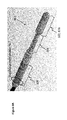
- guidance apparatus 100 comprises head section 102 , neck 104 , handle section 106 and angle adjustment mechanism 110 .
- Angle adjustment mechanism 110 includes needle tube 108 (however skilled persons will appreciate that in some embodiments needle tube 108 may be a separate element capable of removable engagement to angle adjustment mechanism 110 ).
- Apparatus 100 also includes rotation adjustment mechanism 112 .
- head section 102 may be an orifice insertion section, for insertion into an orifice of a patient.
- head section 102 may include imaging apparatus, such as MRI coils for imaging a tissue of interest in a patient when trans-orifice intervention guidance apparatus 100 is in use.
- imaging apparatus such as MRI coils for imaging a tissue of interest in a patient when trans-orifice intervention guidance apparatus 100 is in use.
- head, or coil, section 102 as shown can be inserted into a patient's rectum through the anus and can be positioned proximate to the patient's prostate. The patient can then be positioned in an MRI magnet to obtain images of the patient's prostate for intervention and/or analysis.
- Coil section 102 is connected to handle section 106 by neck 104 .
- neck 104 has a smaller diameter than coil section 102 , which can provide additional patient comfort when coil section 102 is inserted entirely within a patient's rectum, the patient's anus closing around the smaller diameter neck 104 , which can be more comfortable for the patient and can tend to provide additional securement of trans-orifice intervention guidance apparatus 100 when in use.
- coil section 102 can have alternative shapes to account for differently sized coils for different body cavity insertion points and variations in patent anatomy.
- coil section 102 can be comprised of composite tubing to allow coil section 102 to exhibit generally non-rigid properties, capable of conforming to the shape of various organs, imaging needs and/or tissues past the points of body cavity insertion.
- angle adjustment mechanism 110 comprising adjustment slider 202 , tab 204 , saddle 206 , needle tube 108 , track (or slot) 208 and angle scale 210 .
- angle adjustment mechanisms 110 adjusts angle 214 to a desired angle, to allow an interventional device inserted through needle tube 108 to reach a desired anatomical part of a patient when the head, or coil, section 102 and, in some embodiments, a portion of neck 104 , have been inserted into an orifice or existing body cavity of the patient.
- track 208 also tends to prohibit over-extension of an intervention device held by needle tube 108 , and tends to ensure that needle tube 108 travels along a straight path.
- medical instruments such as biopsy needles
- medical instruments can additionally include lasers, electroporators, catheters, or other medical instruments capable of taking biopsies of or delivering treatments to tissue in a patient.
- treatments can include cryotherapy, laser therapy, irreversible electroporation, radiofrequency ablation, radiation marker placement and high and low dose brachytherapy treatment.
- needle tube 108 can include a reusable or sterilizable insert which can be removed and cleaned for further uses.
- lifting tab 204 on saddle 206 allows saddle 206 to be linearly displaced along the length of trans-orifice guidance apparatus 100 (such as along neck section 108 ).
- the path along which saddle 206 can be repositioned may be limited by stopping means such as projections or changes in diameter of trans-orifice guidance apparatus 100 (shown as grooves 230 in the embodiment of FIG. 2F , which can interact with tab 204 to hold saddle 206 into place).
- An alternate release mechanism 254 to tab 206 usable in other embodiments is shown in FIG. 2G , with release achieved by pinching the wings of mechanism 254 .
- angle adjustment mechanism 110 can be displaced in discrete positions along angle scale 210 by slider 202 .
- Angle adjustment mechanism 110 mechanically engages needle tube 108 by saddle 206 and slider 202 .
- needle tube 108 is generally only moving along its longitudinal length through bore 205 of saddle 206 , while it is also engaged to slider 202 , such that movement of slider 202 along saddle 206 , such as over scale 210 , causes angle 214 of needle tube 108 to change as needle tube 108 is moved with slider 202 relative to saddle 206 , as shown in FIG. 2E .
- FIG. 5A shows an embodiment of angle locking mechanism 500 having saddle rails 502 on saddle 206 , and slider clips 504 on slider 202 for engaging rails 502 .
- FIG. 2E when pressure is applied to the slider 202 along the direction 506 ′′ as shown, this tends to flex the slider body and lift slider clips 504 off saddle 206 and saddle rails 502 , allowing the slider 202 to be linearly displaced in along scale 210 . In the embodiment shown, this linear displacement results in an angular displacement of needle tube 108 (as discussed above).
- slider clips 504 will then re-engage saddle rails 502 with sufficient force to hold, or lock, slider 202 and needle tube 108 into place to prevent unwanted movement.
- Skilled persons will appreciate that other means can be used to lock and unlock the slider 202 and/or needle tube 108 , to allow and prevent unwanted linear and/or angle displacement.
- components of angle locking mechanism 500 can be snapped on to handle portion of the probe in one direction and held into place. This removable configuration tends to make the angle locking mechanism 500 , which houses the interventional device, disposable for sanitary purposes.
- FIGS. 5B and 5C An alternative embodiment of frictional engagement mechanism for engaging with rails 502 on saddle 206 , in which the slider has wings that are further spaced apart, is shown in FIGS. 5B and 5C .
- FIGS. 5D and 5E A still further embodiment of an engagement mechanism that uses a latch to secure a slider in place relative to a saddle's rails is shown in FIGS. 5D and 5E .
- angle 214 of needle tube 108 is adjustable between a predefined minimum and predefined maximum.
- this can allow a medical instrument, such as a biopsy needle, to interact with proximal tissue (relative to coil section 102 ) of the patient, and when set at the predefined maximum can allow for interaction with distal tissue (relative to coil section 102 ) of the patient.
- a range of motion of slider 202 such as 4 cm, can translate needle tube 108 along the angular range of 17 to 45 degrees for angle adjustment 110 , while rotation adjustment 112 can provide +/ ⁇ 90 degrees of rotation (or 180 degrees total).
- a user can modify angle 214 by manually adjusting needle tube 108 , which may, or may not be connected to a slider 202 .
- needle tube 108 can be connected to rotate between multiple degrees of freedom, if desired, for example, if needle tube 108 is connected to a gimble joint. Skilled persons will appreciate that other means may be used to adjust angle 214 of needle tube 108 and to hold the desired angle.
- needle lock slide mechanism 600 for use as needle tube 108 .
- mechanism 600 comprises needle tube 608 , joint 602 for engaging with slider 202 , cinching plate 604 and wings 606 .
- Needle lock slide mechanism 600 provides a locking means to restrict unwanted movement of needle tube 608 and any medical instrument therein, such as a biopsy needle, or alternate interventional device, after the linear position of slider 202 has been positioned and/or adjusted.
- a medical instrument such as a biopsy needle, or other interventional device is placed between wings 606 and through the tube.
- wings 606 When pressure is applied to wings 606 , such as by cinching plate 604 being slid over them, wings 606 collapse inward, which can constrict the space between wings 606 , and can lock a medical instrument between wings 606 , such as a biopsy needle, or interventional device into position restricting unwanted movement.
- a medical instrument such as a biopsy needle, or interventional device into position restricting unwanted movement.
- Mechanism 700 comprises needle tube 708 , joint 702 for engaging slider 202 , nut 704 and wings 706 .
- Needle lock screw mechanism 700 can be used to lock the position of a medical instrument, such as a biopsy needle, or other interventional device in a desired position within needle tube 708 .
- a medical instrument such as a biopsy needle, or other interventional device can be positioned between wings 706 and through the tube, and when nut 704 is screwed over wings 706 , wings 706 will tend to collapse inward so as to constrict the space between the wings 706 , and tending to lock an instrument, such as a biopsy needle, into the position it has been currently positioned in and prevent unwanted movement of such instrument.
- rotation adjustment mechanism 112 is shown, comprising dial 302 , hub 304 and rotation scale 306 .
- rotation adjustment mechanism 112 adjusts the rotational position of handle 106 around an axis of rotation that runs through the length of trans-orifice intervention guidance apparatus 100 .
- a user rotates dial 302 in either a clockwise or counterclockwise direction.
- dial 302 is removably engaged to handle section 106 , for example by frictional engagement, and a rotation of handle section results.
- a rotation of the handle section results in rotation of the trans-orifice intervention guidance apparatus 100 .
- dial 302 can engage grooves 987 in handle section 106 shown in FIG. 8A , which rotates relative to same to stationary hub 304 .
- Rotation scale 306 in the embodiment of FIGS. 3A and 3B , includes a display of discrete rotational positions to inform a user of a rotation applied.
- a rotation adjustment mechanism can rotate needle tube, neck and coil sections, while keeping handle section stationary.
- rotation adjustment mechanism 112 includes a locking mechanism, shown in FIGS. 3 and 4 .
- the locking mechanism includes detent 402 , dial 302 and hub 304 .
- detent 402 provides sufficient spring load between hub 304 and dial 302 for self-locking of the rotation mechanism.
- dial 302 contains a pin that engages slot on detent 402 , which restricts movement past a certain point and prevents over rotation of dial 302 .
- any “sticking” of detent 402 and hub 304 interfaces can be prevented by coating surfaces with anti stick-slip materials including, but not limited to, polytetrafluoroethylene.
- a rotation adjustment mechanism can be configured for a rotation of 360 degrees. In other embodiments, the total rotation of a rotation adjustment mechanism can be limited to 90 degrees, or 180 degrees.
- apparatus 802 is shown having head 102 section with imaging component 800 , that is connected to circuitry in handle section 106 .
- Imaging component 800 includes imaging coils 902 embedded therein. These imaging coils 902 can be used to obtain MRI images of a tissue of interest in a patient, such as the patient's prostate, when trans-orifice guidance apparatus 100 is in use. The inclusion of imaging coils 902 in trans-orifice guidance apparatus 100 can allow a user to perform image guided biopsy using trans-orifice guidance apparatus 100 .
- FIG. 8C shows alternative embodiments of apparatus 802 without slots for interventional devices. As shown in FIG.
- fiducial marker 904 which can be MRI visible, can be maintained within coil section 102 and can be seen on a resulting MRI image.
- the position of fiducial marker 904 can be used as a reference point when performing image guided intervention.
- coil section 102 of trans-orifice guidance apparatus 100 is inserted into a patient's bodily cavity, for example the vagina or the rectum.
- imaging coils 902 can be used to generate MRI images of the tissue surrounding intra-orifice intervention guidance apparatus 100 , to identify target tissue locations.
- the rotation adjustment mechanism 112 can be used to position imaging coils 902 in various orientations within the cavity of insertion, allowing the user to select their desired field of image.
- Fiducial marker 904 can be used as a reference point on generated images to facilitate identification of target tissue coordinates.
- a user may refer to images of the patient's tissue, obtained from previous imaging procedures, to identify target tissue for biopsies and intervention. Target tissues can be identified, for example, by an operator's review of captured images.
- software detection systems can be used to analyze medical images and identify localized cell regions or areas of interest for intervention.
- trans-orifice intervention guidance apparatus 100 can additionally be used to guide and position interventional devices such as needles and/or catheters, to a target tissue.
- a user can insert an interventional device, such as a biopsy needle, catheter or other medical instrument, into needle tube 108 , prior to trans-orifice intervention guidance apparatus 100 insertion.
- needles and catheters may be attached to or removed from needle tube 108 after apparatus 100 's insertion, by sliding needle tube 108 and neck 104 outside of the patient's body cavity to provide access to needle tube 108 .
- Neck 104 can then be inserted or reinserted into the body cavity, and angle adjustment mechanism 110 and rotation adjustment mechanism 112 can be used to position needle tube 108 , and the interventional device inserted in needle tube, for guided and controlled access to target tissues.
- imaging and interventional device positioning can be performed concurrently, or as an iterative process, to ensure that all target tissue locations are accessed by the interventional device, such as the needle, catheter or other medical instrument.
- a biopsy can be tracked with coil 902 and magnetic resonance imaging, or other concurrent imaging technology, such as an exterior ultrasound probe that can track the position of the interventional device in the patient.
- the ultrasound image can be co-registered with the MRI image to assist the user in delivering the interventional device to the target tissue location.
- trans-orifice intervention guidance apparatus 100 can be repositioned to improve target tissue contact. Furthermore, in interventional procedures involving several biopsies, trans-orifice guidance apparatus 100 can be repositioned after each biopsy, using imaging and guidance features, without requiring the removal of head 102 from the patient's body.
- FIG. 10 another embodiment of an intervention tool securement and adjustment mechanism is shown, in a transperineal guidance system 1000 , for use in interventional procedures.
- the embodiment of the mechanism shown may be removably attached to an imaging probe, such as to a neck section of the exemplary apparatus 802 shown in FIG. 8 .
- system 1000 may be attached to other imaging devices, or other support structures.
- transperineal guidance system 1000 comprises lock 1002 and frame 1004 .
- apparatus 802 is inserted into frame 1004 where it can be secured with lock 1002 and maintain its position when in use, such as when performing transperineal intervention on a patient.
- coil section 102 is inserted within an existing orifice of a patient, such as the patient's rectum.
- Frame 1004 is used to guide interventional components such as needles and catheters or other medical instruments interperineally through a patient's skin, such as in embodiments where a patient's prostate is being imaged, through the skin between the patient's rectum and scrotum.
- frame 1004 is fastened to neck 104 by frictional engagement with coil lock 1002 .
- Neck 104 is inserted through opening 1006 in frame 1004 and secured into place by mechanically reducing the size of opening 1006 by setting lock 1002 to the locked position.
- transperineal guidance system 1000 includes needle locking system 1100 which secures interventional devices such as needles, catheters or other medical instruments into needle holes 1110 .
- needle locking system 1100 includes front plate 1106 , back plate 1108 , needle hole reference scale 1102 and cam 1104 .
- a knob 1112 is also shown as operating with lock 1002 .
- frame 1004 includes a series of needle holes 1110 through which catheters and needles are placed during interventional procedures.
- Needle hole reference scale 1102 serves as a positioning guide for needle hole locations across the surface of frame 1004 .
- needle hole reference scale 1102 contains an alphabetical scale on one axis and a numerical scale on the other axis, to assist in identifying a spatial location of a particular needle hole across the frame 1004 , which in some embodiments can be determined by image analysis software for guiding a user to a specific needle hole 1110 that will provide access to the desired biopsy location in a tissue of interest.
- cam 1104 can be turned so as to move, front plate 1106 relative to back plate 1108 along a guiding mechanism, such as a rail (not shown), which can provide frictional engagement against an interventional device inserted through a needle hole 1110 of front plate 1106 and back plate 1108 , such as a needle, catheter or other medical instrument.
- a guiding mechanism such as a rail (not shown)
- front plate 1106 and back plate 1108 can be offset to reduce shear forces on needles and control locking force on needles of slightly different diameters.
- FIG. 11B An alternative embodiment of a transperineal guidance system is shown in FIG. 11B , having frame 1204 .
- a needle locking system can operate with an elastomer plate between front and back plates.
- needle locking system 1100 includes elastomer plate 1202 , front plate 1106 and back plate 1108 .
- Elastomer plate 1202 is positioned between front plate 1106 and back plate 1108 .
- front plate 1106 and back plate 1108 are compressed together, exerting compression forces 1204 on elastomer plate 1202 which deforms elastomer plate 1202 and decreases needle hole 1110 diameter, and thus tending to apply compression force on an interventional device inserted in needle hole 1110 and a frictional engagement is formed to prevent unwanted movement of the interventional device.
- elastomer plate can comprise deformable material(s) that is/are biocompatible.
- FIG. 13A shows an embodiment of transperineal guidance system 1300 with single loop coil 1302 embedded in frame 1304 , which is similar to frame 1004 described above (except for the inclusion of coil 1302 therein).
- FIG. 13B shows an alternate embodiment of transperineal guidance system 1344 with single loop butterfly coil 1322 embedded in frame 1324 .
- FIG. 13C shows yet another embodiment, of trasnsperineal guidance system 1340 with a single loop butterfly coil 1342 embedded in frame 1344 .
- a coil such as coils 1302 , 1322 or 1343
- single loop coil 1302 can be used to obtain MRI images of a tissue of interest in a patient, such as the patient's prostate, when transperineal guidance system 1000 is in use.
- the coil embedded within a frame of the guidance system can be used to provide MRI imaging in lieu of, or in addition to, the apparatus to which the system is attached to (such as, for example, the imaging components 800 of apparatus 802 shown in FIG. 8 ).
- coil section 102 of apparatus 800 may be inserted into a patient's bodily cavity, for example the vagina or the rectum.
- a frame as described herein, can be affixed to neck 104 using a coil lock mechanism.
- coils 1302 , 1322 or 1343 , and/or coil section 102 can be used to identify target tissue locations.
- a user may refer to images of the patient's tissue, obtained from previous imaging procedures, to identify target tissue for biopsies and intervention. Target tissues in both instances can be identified, for example, by operator measurements and analysis of images, or by software generated results.
- FIG. 13D shows another embodiment of a transperineal guidance system, which includes fiducial marker 1306 , which can be MRI visible, and can be positioned on frame 1364 (which is similar to frames 1004 , 1154 , 1304 , 1324 and 1344 described above), such that it can be seen on a resulting MRI image.
- fiducial marker 1306 can be used as a reference point when performing image guided intervention.
- template 1402 which can be provided and used as a reference guide for needle locations during interventional procedures using the described guidance systems.
- FIG. 14A shows template 1404 , to assist in planning of interventional procedures. This embodiment can be useful, for example, where previous patient images are available to identify target tissue locations or when the computer image with the targets is not close enough to the patient to be able to target the intervention while looking at this image.
- template, or label, 1404 may be marked at marked locations 1406 that corresponds to an intervention being planned, and then template 1404 may be applied to a frame, such as frame 1154 , for use in a guidance system.
- label 1404 contains a pattern of markers 1406 corresponding to needle holes 1152 on frame 1154 .
- an operator can identify specific needle holes 1152 on frame 1004 to be used in the interventional procedure, and can mark label 1404 accordingly with location markers 1406 .
- Label 1404 can be marked, for example, by shading marker pattern using a printer or by hand. In some embodiments, once label 1404 has been marked, it can be affixed directly to frame 1154 .
- marker 1456 can be inserted onto template 1454 to mark locations for intervention. Template 1454 can then be placed onto a frame (a portion of which is shown in FIG. 14B as 1462 ) and secured in place, for use in guiding interventional procedures.
- marker 1456 may include a hard plastic guide that doubles as a marker, and also having an elastomeric ring 1458 for engaging with template 1460 , as shown in FIG. 14C .
- a needle depth sensor can be integrated into template 1404 or 1460 to provide feedback on needle depth.
- the needle depth sensor can be a small tubular device that can be plugged into needle holes, such as holes 1110 or 1152 (or in the case of marker 1456 , integrated with marker 1456 ) for measuring the distance the interventional device, such as a biopsy needle, catheter or other medical instrument has passed through needle holes by way of either optical or mechanical position encoding.
- interventional devices can be marked with equally spaced markings and light emitter and light receiver technology can be housed inside needle hole (such as 1110 . or 1152 ).
- the light emitter and receive can operate to count the number of markings that have passed through the needle hole, and calculate the corresponding depth that the interventional device has traveled based on the known distance between the marker spacings.
- a mechanical component can, for example, press a spherical roller or ball against the interventional device as it is being inserted through needle holes. Such an embodiment can be used to count the number of turns of the roller or ball, and calculate the depth that the interventional device has traveled.
- an audio or visual signal can be used to alert a user when the depth of the interventional device has reached a desired depth, such as when it has reached the target location in the tissue of the patient.
- an exemplary frame 1484 is shown with Light Emitting Diodes (LEDs) 1488 and embedded programmable chip (not shown).
- the programmable chip is programmed to activate LEDs during interventional procedures, corresponding to particular needle hole (such as holes 1110 ) locations on the reference grid where needle insertion should be made.
- LEDs can be located around two axis' of the frame to create a two dimensional reference grid.
- needle insertion locations can be pre-planned using patient images to identify target tissue locations.
- transperineal guidance system 1500 having a needle angle adaptor comprised of angle plug 1502 and frame 1504 .
- Angle plug 1502 shown in FIG. 15C , comprises angle scale 1506 , angle lock 1508 and intervention device holder 1510 .
- Frame 1504 includes template apertures 1512 to receive, for example, angle plug 1502 .
- angle plug 1502 can be secured to frame, or angle template, 1504 by a portion of plug 1502 to a selected template aperture 1512 .
- angle lock 1508 By engaging angle lock 1508 , device holder 1510 can also be secured at a particular position of angle plug 1502 , which is secured on frame 1504 .
- angle lock 1508 which affixes angle plug 1502 onto frame 1504 at a particular angle to restrict the angular entrance of intervention instruments, such as needles, that are secured to device holder 1510 , such as shown in FIG. 15D .
- intervention instruments such as needles
- FIG. 15D Such embodiments tends to allow for off axis needle insertions which may be required during interventional procedures to negate pubic arch interference, necessary for example, with patients having large prostates.
- Embodiments of angle plugs, their interaction with template apertures, and intervention devices suitable for use therewith, are described in more detail in U.S. patent application Ser. No. 12/822,110, filed Jun. 23, 2010, the contents of which are herein incorporated by reference.
- FIG. 16 alternate configurations of transperineal grids, and needle block shapes and positions, for alternate embodiments for a frame of a transperineal guidance system are shown.
- imaging and intervention can be performed concurrently or as an iterative process, to ensure that all target tissue locations are accessed by the interventional device, such as the needle, catheter or other medical instrument.
- the interventional device such as the needle, catheter or other medical instrument.
- a biopsy can be tracked with image guidance technology, and adjustments to needle locations and angles can be made for subsequent biopsies, without requiring the removal of coil section 102 of apparatus 800 from the patient's orifice or body cavity.
Landscapes
- Health & Medical Sciences (AREA)
- Physics & Mathematics (AREA)
- Life Sciences & Earth Sciences (AREA)
- General Health & Medical Sciences (AREA)
- Pathology (AREA)
- Surgery (AREA)
- Biophysics (AREA)
- Heart & Thoracic Surgery (AREA)
- Medical Informatics (AREA)
- Molecular Biology (AREA)
- Engineering & Computer Science (AREA)
- Animal Behavior & Ethology (AREA)
- Biomedical Technology (AREA)
- Public Health (AREA)
- Veterinary Medicine (AREA)
- Nuclear Medicine, Radiotherapy & Molecular Imaging (AREA)
- General Physics & Mathematics (AREA)
- Condensed Matter Physics & Semiconductors (AREA)
- High Energy & Nuclear Physics (AREA)
- Radiology & Medical Imaging (AREA)
- Magnetic Resonance Imaging Apparatus (AREA)
Abstract
Description
Claims (16)
Priority Applications (2)
| Application Number | Priority Date | Filing Date | Title |
|---|---|---|---|
| US13/304,573 US9913596B2 (en) | 2010-11-25 | 2011-11-25 | Systems and methods for MRI guided trans-orifice and transperineal intervention apparatus with adjustable biopsy needle insertion |
| US15/883,399 US20180199851A1 (en) | 2010-11-25 | 2018-01-30 | Systems and methods for trans-orifice and transperineal intervention |
Applications Claiming Priority (3)
| Application Number | Priority Date | Filing Date | Title |
|---|---|---|---|
| US41727110P | 2010-11-25 | 2010-11-25 | |
| US41727010P | 2010-11-25 | 2010-11-25 | |
| US13/304,573 US9913596B2 (en) | 2010-11-25 | 2011-11-25 | Systems and methods for MRI guided trans-orifice and transperineal intervention apparatus with adjustable biopsy needle insertion |
Related Child Applications (1)
| Application Number | Title | Priority Date | Filing Date |
|---|---|---|---|
| US15/883,399 Division US20180199851A1 (en) | 2010-11-25 | 2018-01-30 | Systems and methods for trans-orifice and transperineal intervention |
Publications (2)
| Publication Number | Publication Date |
|---|---|
| US20120203095A1 US20120203095A1 (en) | 2012-08-09 |
| US9913596B2 true US9913596B2 (en) | 2018-03-13 |
Family
ID=46601102
Family Applications (3)
| Application Number | Title | Priority Date | Filing Date |
|---|---|---|---|
| US13/304,583 Active 2034-12-08 US9332926B2 (en) | 2010-11-25 | 2011-11-25 | MRI imaging probe |
| US13/304,573 Active 2036-06-03 US9913596B2 (en) | 2010-11-25 | 2011-11-25 | Systems and methods for MRI guided trans-orifice and transperineal intervention apparatus with adjustable biopsy needle insertion |
| US15/883,399 Abandoned US20180199851A1 (en) | 2010-11-25 | 2018-01-30 | Systems and methods for trans-orifice and transperineal intervention |
Family Applications Before (1)
| Application Number | Title | Priority Date | Filing Date |
|---|---|---|---|
| US13/304,583 Active 2034-12-08 US9332926B2 (en) | 2010-11-25 | 2011-11-25 | MRI imaging probe |
Family Applications After (1)
| Application Number | Title | Priority Date | Filing Date |
|---|---|---|---|
| US15/883,399 Abandoned US20180199851A1 (en) | 2010-11-25 | 2018-01-30 | Systems and methods for trans-orifice and transperineal intervention |
Country Status (1)
| Country | Link |
|---|---|
| US (3) | US9332926B2 (en) |
Cited By (1)
| Publication number | Priority date | Publication date | Assignee | Title |
|---|---|---|---|---|
| US10849650B2 (en) * | 2015-07-07 | 2020-12-01 | Eigen Health Services, Llc | Transperineal needle guidance |
Families Citing this family (20)
| Publication number | Priority date | Publication date | Assignee | Title |
|---|---|---|---|---|
| US11612377B2 (en) * | 2010-12-16 | 2023-03-28 | Best Medical International, Inc. | Image guided surgical methodology and system employing patient movement detection and correction |
| EP2967292A4 (en) * | 2013-03-15 | 2017-03-01 | Synaptive Medical (Barbados) Inc. | Systems and methods for navigation and simulation of minimally invasive therapy |
| US9730762B2 (en) * | 2013-03-15 | 2017-08-15 | Neocoil, Llc | Automatic needle insertion location identification |
| WO2014138923A1 (en) * | 2013-03-15 | 2014-09-18 | Synaptive Medical (Barbados) Inc. | Insert imaging device for surgical procedures |
| EP2996567B1 (en) * | 2013-04-12 | 2022-08-17 | Koninklijke Philips N.V. | Imaging apparatus for brachytherapy or biopsy |
| DE102013113277A1 (en) | 2013-11-29 | 2015-06-03 | Hubert Noras | Needle guide for biopsy |
| DE102013113272A1 (en) | 2013-11-29 | 2015-06-03 | Hubert Noras | Needle guiding device for biopsy |
| WO2015128203A1 (en) * | 2014-02-25 | 2015-09-03 | Koninklijke Philips N.V. | Needle guide and medical intervention system |
| US10743909B2 (en) | 2014-04-03 | 2020-08-18 | Corbin Clinical Resources, Llc | Transperineal prostate biopsy device, systems, and methods of use |
| US10238363B2 (en) * | 2014-08-21 | 2019-03-26 | Richard D. Striano | Needle guide for ultrasound transducer |
| US10772602B2 (en) | 2014-11-25 | 2020-09-15 | Koninklijke Philips N.V. | System for monitoring a use of a medical device |
| US10517706B2 (en) * | 2015-02-04 | 2019-12-31 | Desvac | Portable automatic veterinary injector device |
| WO2016135594A1 (en) * | 2015-02-27 | 2016-09-01 | Faber Industrie S.P.A. | Apparatus and method for positioning medical instruments assisted by indirect visualization |
| EP3261551A1 (en) * | 2015-02-27 | 2018-01-03 | Faber Industrie S.p.A. | Indirect visualization-assisted apparatus and method for positioning medical instruments |
| DE102015208420A1 (en) * | 2015-05-06 | 2016-11-10 | Siemens Healthcare Gmbh | Temperature determination by means of an intervention device |
| JP6969929B2 (en) * | 2017-08-24 | 2021-11-24 | 株式会社日本マイクロニクス | Probe and its manufacturing method |
| KR20200086049A (en) * | 2019-01-08 | 2020-07-16 | 삼성메디슨 주식회사 | Ultrasonic probe |
| CN109655773B (en) * | 2019-01-22 | 2020-03-20 | 厦门大学 | Pluggable roll-printing coil probe of nuclear magnetic resonance apparatus and design method thereof |
| CN112220533B (en) * | 2020-10-19 | 2022-02-08 | 苏州法兰克曼医疗器械有限公司 | Multi-angle adjustable B-ultrasonic puncture positioning frame |
| CN112569460B (en) * | 2020-11-06 | 2022-12-09 | 哈尔滨理工大学 | Prostate closely particle implantation needle adjusting device |
Citations (7)
| Publication number | Priority date | Publication date | Assignee | Title |
|---|---|---|---|---|
| US4838506A (en) * | 1988-06-15 | 1989-06-13 | Cooper William I | Guidance device for ultrasound guided surgical procedures |
| US4911173A (en) * | 1987-11-13 | 1990-03-27 | Diasonics, Inc. | Biopsy attachment for ultrasound probe |
| US5871448A (en) * | 1997-10-14 | 1999-02-16 | Real World Design And Development Co. | Stepper apparatus for use in the imaging/treatment of internal organs using an ultrasound probe |
| US20080216239A1 (en) * | 2003-09-30 | 2008-09-11 | Christopher Alexander Luginbuhl | Supine patient support for medical imaging |
| US20100036245A1 (en) * | 2005-12-02 | 2010-02-11 | Yan Yu | Image-guided therapy delivery and diagnostic needle system |
| US20100056900A1 (en) * | 2006-03-14 | 2010-03-04 | The John Hopkins University | Apparatus for insertion of a medical device within a body during a medical imaging process and devices and methods related thereto |
| US20110218444A1 (en) * | 2010-03-02 | 2011-09-08 | Civco Medical Instruments Co., Inc. | Hinged reusable endocavity needle guide |
Family Cites Families (185)
| Publication number | Priority date | Publication date | Assignee | Title |
|---|---|---|---|---|
| US3115140A (en) | 1960-08-18 | 1963-12-24 | Baltimore Instr Company | Apparatus for stereotaxic brain operations |
| US3523251A (en) * | 1967-02-27 | 1970-08-04 | William S Halstead | Antenna structure with an integrated amplifier responsive to signals of varied polarization |
| DE3218328A1 (en) | 1982-05-14 | 1983-11-17 | Stierlen-Maquet Ag, 7550 Rastatt | OPERATING TABLE |
| US4503844A (en) | 1983-01-13 | 1985-03-12 | Fischer Imaging Corporation | Surgical table |
| US4572203A (en) | 1983-01-27 | 1986-02-25 | Feinstein Steven B | Contact agents for ultrasonic imaging |
| US4930516B1 (en) | 1985-11-13 | 1998-08-04 | Laser Diagnostic Instr Inc | Method for detecting cancerous tissue using visible native luminescence |
| US4733661A (en) | 1987-04-27 | 1988-03-29 | Palestrant Aubrey M | Guidance device for C.T. guided drainage and biopsy procedures |
| US4989608A (en) | 1987-07-02 | 1991-02-05 | Ratner Adam V | Device construction and method facilitating magnetic resonance imaging of foreign objects in a body |
| US5154179A (en) | 1987-07-02 | 1992-10-13 | Medical Magnetics, Inc. | Device construction and method facilitating magnetic resonance imaging of foreign objects in a body |
| US4825162A (en) | 1987-12-07 | 1989-04-25 | General Electric Company | Nuclear magnetic resonance (NMR) imaging with multiple surface coils |
| US4943986A (en) | 1988-10-27 | 1990-07-24 | Leonard Barbarisi | Mammography compression apparatus for prosthetically augmented breast |
| NL8802874A (en) | 1988-11-22 | 1990-06-18 | Philips Nv | PATIENT POSITIONING AND TRANSPORT SYSTEM, PATIENT TABLE, TROLLEY AND TABLETOP FOR USE IN SUCH A SYSTEM. |
| US4930525A (en) | 1989-03-28 | 1990-06-05 | Palestrant Aubrey M | Method for performing C.T. guided drainage and biopsy procedures |
| DE3915381A1 (en) | 1989-05-11 | 1990-11-15 | Dornier Medizintechnik | BED FOR A LITHOTRIPTER |
| US5047036A (en) | 1989-11-17 | 1991-09-10 | Koutrouvelis Panos G | Stereotactic device |
| US5308352A (en) | 1989-11-17 | 1994-05-03 | Koutrouvelis Panos G | Stereotactic device |
| US5158088A (en) * | 1990-11-14 | 1992-10-27 | Advanced Technology Laboratories, Inc. | Ultrasonic diagnostic systems for imaging medical instruments within the body |
| CA2010390A1 (en) * | 1990-02-20 | 1991-08-20 | Robert Keith Harman | Open transmission line locating system |
| US5096216A (en) | 1990-12-20 | 1992-03-17 | Mccalla William R | Transport trailer with collapsible shelves, and method of using such trailer |
| US5569266A (en) | 1991-03-11 | 1996-10-29 | Fischer Imaging Corporation | Magnetic resonance imaging device useful for guiding a medical instrument |
| US6723303B1 (en) | 1991-09-17 | 2004-04-20 | Amersham Health, As | Ultrasound contrast agents including protein stabilized microspheres of perfluoropropane, perfluorobutane or perfluoropentane |
| US5196019A (en) | 1991-10-04 | 1993-03-23 | Dlp, Inc. | Goniometer for needle placement |
| US5289520A (en) | 1991-11-27 | 1994-02-22 | Lorad Corporation | Stereotactic mammography imaging system with prone position examination table and CCD camera |
| US6697659B1 (en) | 1991-12-04 | 2004-02-24 | Bonutti 2003 Trust-A | Method of imaging a joint in a body of patient |
| US6229145B1 (en) | 1992-01-22 | 2001-05-08 | Pem Technologies, Inc. | Dedicated apparatus and method emission mammography |
| DE4225001C1 (en) | 1992-07-29 | 1993-11-18 | Siemens Ag | Stereo-tactic additional device for nuclear spin tomography for investigation of mammary disorders - has two compression plates parallel and displaceable towards one another, between which object for investigation e.g breast is positioned |
| US5297551A (en) | 1992-08-06 | 1994-03-29 | Picker International, Inc. | Weighted ray projection imaging for MR angiography |
| US6005916A (en) | 1992-10-14 | 1999-12-21 | Techniscan, Inc. | Apparatus and method for imaging with wavefields using inverse scattering techniques |
| JP3860227B2 (en) | 1993-03-10 | 2006-12-20 | 株式会社東芝 | Ultrasonic therapy device used under MRI guide |
| US5594337A (en) | 1993-05-07 | 1997-01-14 | Medical Advances, Inc. | Local coil for magnetic resonance angiography |
| US5590655A (en) | 1993-09-20 | 1997-01-07 | Hussman; Karl L. | Frameless laser guided stereotactic localization system |
| DE69534233T2 (en) | 1994-09-16 | 2005-10-27 | Ethicon Endo-Surgery, Inc., Cincinnati | DEVICES FOR DETERMINING AND MARKING TISSUE |
| DE69432605T2 (en) | 1994-09-16 | 2004-02-26 | Fischer Imaging Corp., Denver | MAGNETIC RESONANCE DISPLAY DEVICE FOR TOOLING |
| US5626829A (en) | 1994-11-16 | 1997-05-06 | Pgk, Enterprises, Inc. | Method and apparatus for interstitial radiation of the prostate gland |
| US5682890A (en) | 1995-01-26 | 1997-11-04 | Picker International, Inc. | Magnetic resonance stereotactic surgery with exoskeleton tissue stabilization |
| US5868673A (en) | 1995-03-28 | 1999-02-09 | Sonometrics Corporation | System for carrying out surgery, biopsy and ablation of a tumor or other physical anomaly |
| US5594339A (en) | 1995-07-11 | 1997-01-14 | Picker International, Inc. | Flexible nuclear magnetic resonance receiver coils and systems |
| US5548218A (en) | 1995-10-19 | 1996-08-20 | North Shore University Hospital Research Corporation | Flexible RF coils for MRI system |
| US5782764A (en) | 1995-11-07 | 1998-07-21 | Iti Medical Technologies, Inc. | Fiber composite invasive medical instruments and methods for use in interventional imaging procedures |
| US5744958A (en) | 1995-11-07 | 1998-04-28 | Iti Medical Technologies, Inc. | Instrument having ultra-thin conductive coating and method for magnetic resonance imaging of such instrument |
| US5706812A (en) | 1995-11-24 | 1998-01-13 | Diagnostic Instruments, Inc. | Stereotactic MRI breast biopsy coil and method for use |
| US5944023A (en) | 1995-12-07 | 1999-08-31 | Sims Deltec, Inc. | Systems and methods for determining the location of an implanted device including a magnet |
| US6163616A (en) | 1995-12-29 | 2000-12-19 | Feldman; Stephen E. | System and method for verifying the identity of a person |
| US5682098A (en) | 1996-01-11 | 1997-10-28 | W. L. Gore & Associates, Inc. | Open quadrature whole volume imaging NMR surface coil array including three figure-8 shaped surface coils |
| US6263229B1 (en) * | 1998-11-13 | 2001-07-17 | Johns Hopkins University School Of Medicine | Miniature magnetic resonance catheter coils and related methods |
| US5900228A (en) | 1996-07-31 | 1999-05-04 | California Institute Of Technology | Bifunctional detection agents having a polymer covalently linked to an MRI agent and an optical dye |
| US5855554A (en) | 1997-03-17 | 1999-01-05 | General Electric Company | Image guided breast lesion localization device |
| US5817023A (en) | 1997-05-12 | 1998-10-06 | General Electrical Company | Ultrasound imaging system with dynamic window function generator |
| US6021342A (en) | 1997-06-30 | 2000-02-01 | Neorad A/S | Apparatus for assisting percutaneous computed tomography-guided surgical activity |
| US6201392B1 (en) | 1997-11-07 | 2001-03-13 | Varian, Inc. | Coplanar RF probe coil arrangement for multifrequency excitation |
| US6051974A (en) | 1997-11-26 | 2000-04-18 | Picker International, Inc. | MRI endocavitary coils and decontamination |
| IL122839A0 (en) | 1997-12-31 | 1998-08-16 | Ultra Guide Ltd | Calibration method and apparatus for calibrating position sensors on scanning transducers |
| US6091985A (en) | 1998-01-23 | 2000-07-18 | Research Foundation Of City College Of New York | Detection of cancer and precancerous conditions in tissues and/or cells using native fluorescence excitation spectroscopy |
| US6295671B1 (en) | 1998-03-06 | 2001-10-02 | Ohio Medical Instrument Company, Inc. | Medical surgical table including interchangeable orthopedic attachment and scanning table |
| US6066102A (en) | 1998-03-09 | 2000-05-23 | Spectrascience, Inc. | Optical biopsy forceps system and method of diagnosing tissue |
| US6174291B1 (en) | 1998-03-09 | 2001-01-16 | Spectrascience, Inc. | Optical biopsy system and methods for tissue diagnosis |
| US6282738B1 (en) | 1998-08-07 | 2001-09-04 | Hill-Rom, Inc. | Ob/Gyn stretcher |
| DE19853463B4 (en) | 1998-11-19 | 2005-08-11 | Siemens Ag | Multiple examination arrangement with a variety of imaging systems |
| US6159221A (en) | 1998-11-25 | 2000-12-12 | The Ohio State University | Stereotactic apparatus and methods |
| US6163717A (en) | 1998-11-25 | 2000-12-19 | Toshiba America Mri, Inc. | Open structure breast coil and support arrangement for interventional MRI |
| EP1161178A2 (en) | 1998-12-23 | 2001-12-12 | Medispectra Inc. | Systems and methods for optical examination of samples |
| US6281681B1 (en) | 1999-01-28 | 2001-08-28 | General Electric Company | Magnetic resonance imaging with interleaved Fibonacci spiral scanning |
| DE19915852C2 (en) | 1999-04-08 | 2003-12-24 | Siemens Ag | Urological patient bed |
| US6421454B1 (en) | 1999-05-27 | 2002-07-16 | Litton Systems, Inc. | Optical correlator assisted detection of calcifications for breast biopsy |
| US6470204B1 (en) * | 1999-08-25 | 2002-10-22 | Egidijus Edward Uzgiris | Intracavity probe for MR image guided biopsy and delivery of therapy |
| EP1225833A4 (en) | 1999-09-14 | 2003-11-26 | Papillon Surgical | Breast bracket |
| US6675037B1 (en) | 1999-09-29 | 2004-01-06 | Regents Of The University Of Minnesota | MRI-guided interventional mammary procedures |
| CA2388757C (en) | 1999-10-18 | 2010-01-05 | National Research Council Of Canada | Magnetic resonance spectroscopy of breast biopsy to determine pathology, vascularization and nodal involvement |
| US6987831B2 (en) | 1999-11-18 | 2006-01-17 | University Of Rochester | Apparatus and method for cone beam volume computed tomography breast imaging |
| US6437567B1 (en) | 1999-12-06 | 2002-08-20 | General Electric Company | Radio frequency coil for open magnetic resonance imaging system |
| US6446286B1 (en) | 2000-02-07 | 2002-09-10 | Koninklijke Philips Electronics N.V. | Patient support table for medical imaging having regions for reduced radiation attenuation |
| AU779659B2 (en) | 2000-02-08 | 2005-02-03 | Cornell Research Foundation Inc. | Multiphoton excitation through optical fibers for fluorescence spectroscopy |
| US6324243B1 (en) | 2000-02-23 | 2001-11-27 | General Electric Company | Method and apparatus for reconstructing images from projection data acquired by a computed tomography system |
| AU2001251114A1 (en) | 2000-03-28 | 2001-10-08 | Board Of Regents, The University Of Texas System | Enhancing contrast in biological imaging |
| US6889073B2 (en) | 2000-05-08 | 2005-05-03 | David A. Lampman | Breast biopsy and therapy system for magnetic resonance imagers |
| EP1296610A2 (en) | 2000-06-22 | 2003-04-02 | Nuvasive, Inc. | Polar coordinate surgical guideframe |
| US6904630B2 (en) | 2000-07-21 | 2005-06-14 | Siemens Medical Solutions Usa, Inc. | Tabletop for radiation therapy and diagnostic imaging |
| CA2314794A1 (en) | 2000-08-01 | 2002-02-01 | Dimitre Hristov | Apparatus for lesion or organ localization |
| US7024711B1 (en) | 2000-08-31 | 2006-04-11 | Stasney T Glen | Sonography bed having patient support and sonographer access provisions |
| AU2001296738A1 (en) | 2000-10-09 | 2002-04-22 | Regents Of The University Of Minnesota | Method and apparatus for magnetic resonance imaging and spectroscopy using microstrip transmission line coils |
| US6628983B1 (en) | 2000-10-25 | 2003-09-30 | Koninklijke Philips Electronics N.V. | Nuclear imaging systems and methods with feature-enhanced transmission imaging |
| US6591128B1 (en) | 2000-11-09 | 2003-07-08 | Koninklijke Philips Electronics, N.V. | MRI RF coil systems having detachable, relocatable, and or interchangeable sections and MRI imaging systems and methods employing the same |
| US6501980B1 (en) | 2000-11-09 | 2002-12-31 | Koninklijke Philips Electronics N.V. | Easily decontaminated MRI endocavity coils |
| US6832399B2 (en) | 2000-11-14 | 2004-12-21 | Michael G. Falbo, Sr. | Breast biopsy bed |
| US6459923B1 (en) | 2000-11-22 | 2002-10-01 | General Electric Company | Intervention bed for a medical imaging device |
| US7556602B2 (en) | 2000-11-24 | 2009-07-07 | U-Systems, Inc. | Breast cancer screening with adjunctive ultrasound mammography |
| US6841388B2 (en) | 2000-12-05 | 2005-01-11 | Vysis, Inc. | Method and system for diagnosing pathology in biological samples by detection of infrared spectral markers |
| US20020073717A1 (en) | 2000-12-19 | 2002-06-20 | Dean David E. | MR scanner including liquid cooled RF coil and method |
| US6697652B2 (en) | 2001-01-19 | 2004-02-24 | Massachusetts Institute Of Technology | Fluorescence, reflectance and light scattering spectroscopy for measuring tissue |
| GB0103030D0 (en) | 2001-02-07 | 2001-03-21 | Univ London | Spectrum processing and processor |
| US6832108B2 (en) | 2001-04-19 | 2004-12-14 | Koninklijke Philips Electronics, N.V. | Endovaginal MRI receiver coil |
| US6498489B1 (en) | 2001-05-04 | 2002-12-24 | Kamal Vij | Magnetic resonance imaging coil arrays with separable imaging coil elements |
| DE10126338A1 (en) | 2001-05-30 | 2002-12-12 | Siemens Ag | High frequency coil arrangement for an NMR imaging device in which both surface and circumferential coils receive the same polarization component |
| US20030055436A1 (en) | 2001-09-14 | 2003-03-20 | Wolfgang Daum | Navigation of a medical instrument |
| WO2003039212A1 (en) | 2001-10-30 | 2003-05-08 | Loma Linda University Medical Center | Method and device for delivering radiotherapy |
| US7024027B1 (en) | 2001-11-13 | 2006-04-04 | Koninklijke Philips Electronics N.V. | Method and apparatus for three-dimensional filtering of angiographic volume data |
| US7020314B1 (en) | 2001-11-13 | 2006-03-28 | Koninklijke Philips Electronics N.V. | Black blood angiography method and apparatus |
| US7155043B2 (en) | 2001-11-21 | 2006-12-26 | Confirma, Incorporated | User interface having analysis status indicators |
| US6640364B1 (en) | 2001-11-30 | 2003-11-04 | Ge Medical Systems Global Technololgy Company, Llc | Pedestal for use with patient transport system for multiple imaging systems |
| US20050114887A1 (en) | 2002-03-08 | 2005-05-26 | Gelissen Johan H.A. | Quality of video |
| US20030194050A1 (en) | 2002-04-15 | 2003-10-16 | General Electric Company | Multi modality X-ray and nuclear medicine mammography imaging system and method |
| US7769426B2 (en) | 2002-04-23 | 2010-08-03 | Ethicon Endo-Surgery, Inc. | Method for using an MRI compatible biopsy device with detachable probe |
| US20030199753A1 (en) | 2002-04-23 | 2003-10-23 | Ethicon Endo-Surgery | MRI compatible biopsy device with detachable probe |
| US6822450B2 (en) | 2002-04-26 | 2004-11-23 | Ge Medical Systems Global Technology Company, Llc | Multiple channel, cardiac array for sensitivity encoding in magnetic resonance imaging |
| US20030206019A1 (en) | 2002-05-02 | 2003-11-06 | Boskamp Eddy B. | Wireless RF module for an MR imaging system |
| US6639406B1 (en) | 2002-05-08 | 2003-10-28 | Ge Medical Systems Global Technology Company, Llc | Method and apparatus for decoupling quadrature phased array coils |
| US6941599B2 (en) | 2002-08-20 | 2005-09-13 | Aktina Medical Corp. | Radiotherapy treatment and imaging patient support table |
| US7438692B2 (en) | 2002-10-18 | 2008-10-21 | Mark Tsonton | Localization mechanism for an MRI compatible biopsy device |
| US6927406B2 (en) | 2002-10-22 | 2005-08-09 | Iso-Science Laboratories, Inc. | Multimodal imaging sources |
| US6922859B2 (en) | 2002-11-29 | 2005-08-02 | Art Advanced Research Technologies Inc. | Table for positioning a patient for a medical procedure on a breast |
| DE10253877A1 (en) | 2002-11-12 | 2004-05-27 | Trumpf Medizin Systeme Gmbh | Plate-shaped device for supporting a body part of a patient |
| US6867593B2 (en) | 2002-11-22 | 2005-03-15 | Igc-Medical Advances, Inc. | Modular local coil set for magnetic resonance imaging |
| US6810595B2 (en) | 2002-12-24 | 2004-11-02 | Wing-Sheung Chan | Laser angle guide assembly for computed tomography and method for the same |
| US20050059877A1 (en) | 2003-01-17 | 2005-03-17 | Falbo Michael G. | Imaging table support surface |
| US7049819B2 (en) | 2003-01-21 | 2006-05-23 | General Electric Company | Diagonal-arranged quadrature MRI radio frequency array coil system for three dimensional parallel imaging |
| US20060026761A1 (en) | 2003-03-03 | 2006-02-09 | Falbo Michael G | Sonographers extension |
| US7545966B2 (en) | 2003-05-05 | 2009-06-09 | Case Western Reserve University | Efficient methods for reconstruction and deblurring of magnetic resonance images |
| US6950492B2 (en) | 2003-06-25 | 2005-09-27 | Besson Guy M | Dynamic multi-spectral X-ray projection imaging |
| US20050033315A1 (en) | 2003-08-01 | 2005-02-10 | Hankins Carol A. | Apparatus and method for guiding a medical device |
| DE10337932B4 (en) | 2003-08-18 | 2009-02-05 | Siemens Ag | Apparatus and method for minimizing stripe artifacts in radial or helical k-space sampling in magnetic resonance imaging |
| US7313430B2 (en) | 2003-08-28 | 2007-12-25 | Medtronic Navigation, Inc. | Method and apparatus for performing stereotactic surgery |
| US7379769B2 (en) | 2003-09-30 | 2008-05-27 | Sunnybrook Health Sciences Center | Hybrid imaging method to monitor medical device delivery and patient support for use in the method |
| US20080077005A1 (en) | 2004-08-12 | 2008-03-27 | Piron Cameron A | System and Method for Multimodality Breast Imaging |
| US7970452B2 (en) | 2003-09-30 | 2011-06-28 | Hologic, Inc. | Open architecture imaging apparatus and coil system for magnetic resonance imaging |
| EP1689290A2 (en) | 2003-10-21 | 2006-08-16 | The Board of Trustees of The Leland Stanford Junior University | Systems and methods for intraoperative targeting |
| US7084631B2 (en) | 2003-11-19 | 2006-08-01 | General Electric Company | Magnetic resonance imaging array coil system and method for breast imaging |
| WO2005065337A2 (en) | 2003-12-29 | 2005-07-21 | Hankins Carol A | Apparatus and method for guiding a medical device in multiple planes |
| US20080234569A1 (en) | 2004-01-20 | 2008-09-25 | Topspin Medical (Israel) Ltd. | Mri Probe for Prostate Imaging |
| US20050228267A1 (en) | 2004-04-08 | 2005-10-13 | General Electric Company | Method and apparatus for improved breast imaging |
| US7809426B2 (en) | 2004-04-29 | 2010-10-05 | The Cleveland Clinic Foundation | Acquiring contrast-enhanced, T1 weighted, cine magnetic resonance images |
| US20060106303A1 (en) * | 2004-05-18 | 2006-05-18 | The Johns Hopkins University | Interventional devices for chronic total occlusion recanalization under MRI guidance |
| US7708751B2 (en) | 2004-05-21 | 2010-05-04 | Ethicon Endo-Surgery, Inc. | MRI biopsy device |
| US20050267373A1 (en) | 2004-05-28 | 2005-12-01 | Doohi Lee | Tool insertion guidance device for use with a medical imaging system |
| WO2006017172A1 (en) | 2004-07-09 | 2006-02-16 | Fischer Imaging Corporation | Diagnostic system for multimodality mammography |
| US20060024132A1 (en) | 2004-08-02 | 2006-02-02 | Seman Todd J | Tactile warning system |
| USD533278S1 (en) | 2004-08-12 | 2006-12-05 | Chris Luginbuhl | Patient support for prone imaging and intervention table |
| USD569977S1 (en) | 2004-08-12 | 2008-05-27 | Sentinelle Medical Inc. | Patient support for prone imaging and intervention table |
| US7131769B2 (en) | 2004-12-16 | 2006-11-07 | Octostop Inc. | Stretcher with dedicated multi-functional removable floating patient support platform |
| DE102005003380A1 (en) | 2005-01-24 | 2006-08-03 | Innomedic Gmbh | holder |
| US8126537B2 (en) | 2005-02-04 | 2012-02-28 | General Electric Company | Method and apparatus for a multi-modality imaging system |
| US20060221942A1 (en) | 2005-03-31 | 2006-10-05 | Frank Fruth | Intelligent voice network monitoring |
| US7176683B2 (en) | 2005-05-06 | 2007-02-13 | The Board Of Trustees Of The Leland Stanford Junior University | Iterative decomposition of water and fat with echo asymmetry and least square estimation |
| US20070039101A1 (en) | 2005-06-03 | 2007-02-22 | Sentinelle Medical, Inc. | Specialized tabletops for medical imaging |
| US7245694B2 (en) | 2005-08-15 | 2007-07-17 | Hologic, Inc. | X-ray mammography/tomosynthesis of patient's breast |
| US8276225B2 (en) | 2005-08-23 | 2012-10-02 | General Electric Company | Methods and systems for patient positioning in an imaging system |
| US7742796B2 (en) | 2005-10-25 | 2010-06-22 | General Electric Company | Breast immobilization device and method of imaging the breast |
| US7832401B2 (en) | 2005-11-30 | 2010-11-16 | Smith & Nephew, Inc. | Hip distraction |
| US7740593B2 (en) | 2005-12-09 | 2010-06-22 | Senorx, Inc | Guide block for biopsy or surgical devices |
| US7945308B2 (en) * | 2005-12-27 | 2011-05-17 | General Electric Company | Systems, methods and apparatus for an endo-rectal receive-only probe |
| JP2007175431A (en) | 2005-12-28 | 2007-07-12 | Olympus Medical Systems Corp | Ultrasonograph |
| CN100518675C (en) | 2006-01-23 | 2009-07-29 | 张惠玲 | Guiding puncture needling tool and puncture guiding method |
| US7676255B2 (en) | 2006-03-20 | 2010-03-09 | Siemens Medical Solutions Usa, Inc. | System and method for supporting a patient during medical imaging |
| US20070233157A1 (en) | 2006-03-29 | 2007-10-04 | Mark Joseph L | Flexible needle guide |
| US8568333B2 (en) | 2006-05-01 | 2013-10-29 | Devicor Medical Products, Inc. | Grid and rotatable cube guide localization fixture for biopsy device |
| US7507210B2 (en) | 2006-05-01 | 2009-03-24 | Ethicon Endo-Surgery, Inc. | Biopsy cannula adjustable depth stop |
| EP2040614B1 (en) | 2006-07-05 | 2016-01-27 | Stryker Corporation | A system for detecting and monitoring vital signs |
| DE102006038163A1 (en) | 2006-08-16 | 2008-02-21 | Siemens Ag | Compression device and method for adjusting a compression pressure |
| US7373676B2 (en) | 2006-09-21 | 2008-05-20 | Aktina Medical Corporation | Patient support apparatus and method therefor |
| US8126239B2 (en) | 2006-10-20 | 2012-02-28 | Siemens Aktiengesellschaft | Registering 2D and 3D data using 3D ultrasound data |
| CN101641748B (en) | 2006-11-21 | 2013-06-05 | 洛马林达大学医学中心 | Device and method for immobilizing patients for breast radiation therapy |
| US20100053300A1 (en) | 2007-02-02 | 2010-03-04 | Einarsson Torbjoern | Method And Arrangement For Video Telephony Quality Assessment |
| US7597104B2 (en) | 2007-03-23 | 2009-10-06 | Zheng Mike Q | Method and device for immobilization of the human breast in a prone position for radiotherapy |
| US8155417B2 (en) | 2007-03-27 | 2012-04-10 | Hologic, Inc. | Post-acquisition adaptive reconstruction of MRI data |
| JP2011511652A (en) | 2007-11-14 | 2011-04-14 | コーニンクレッカ フィリップス エレクトロニクス エヌ ヴィ | System and method for automatic calibration of tracked ultrasound |
| US8290569B2 (en) | 2007-11-23 | 2012-10-16 | Hologic, Inc. | Open architecture tabletop patient support and coil system |
| US8374676B2 (en) | 2007-11-23 | 2013-02-12 | Hologic, Inc. | Chest wall coil array for breast imaging |
| JP5278728B2 (en) | 2008-02-28 | 2013-09-04 | アイシン精機株式会社 | Distance image sensor calibration apparatus and calibration method |
| EP2105107A1 (en) | 2008-03-27 | 2009-09-30 | BrainLAB AG | Method for calibrating axial medicinal or medical technical instruments |
| US8532748B2 (en) | 2008-04-23 | 2013-09-10 | Devicor Medical Products, Inc. | Devices useful in imaging |
| US9052384B2 (en) | 2008-05-22 | 2015-06-09 | The Trustees Of Dartmouth College | System and method for calibration for image-guided surgery |
| WO2010019795A2 (en) | 2008-08-13 | 2010-02-18 | John Schlitt | Needle guides for catheter delivery |
| JP5259346B2 (en) | 2008-11-05 | 2013-08-07 | 富士フイルム株式会社 | Biopsy equipment |
| WO2010078048A2 (en) | 2008-12-17 | 2010-07-08 | Therapy Positioning Technologies, Llc | Apparatus and method for concurrent tensive and compressive immobilization of the breast in imaging and intervention |
| US8206314B2 (en) | 2009-06-17 | 2012-06-26 | Devicor Medical Products, Inc. | MRI biopsy targeting grid with round openings |
| US20100324445A1 (en) | 2009-06-17 | 2010-12-23 | Mollere Rebecca J | MRI Biopsy Cylindraceous Targeting Guide |
| US8747331B2 (en) | 2009-06-23 | 2014-06-10 | Hologic, Inc. | Variable angle guide holder for a biopsy guide plug |
| WO2011014966A1 (en) | 2009-08-06 | 2011-02-10 | Sentinelle Medical Inc. | Apparatus and method for substantially immobilizing a breast for medical imaging procedures |
| US8298245B2 (en) | 2009-08-17 | 2012-10-30 | Chang Gung University | Three-dimensional positioning device for minimally invasive surgery |
| US8162847B2 (en) | 2009-10-16 | 2012-04-24 | Devicor Medical Products, Inc. | MRI biopsy targeting cube with snap corners |
| US8162848B2 (en) | 2009-10-16 | 2012-04-24 | Devicor Medical Products, Inc. | MRI biopsy targeting cube with eccentric lock |
| US8162849B2 (en) | 2009-10-16 | 2012-04-24 | Devicor Medical Products, Inc. | MRI biopsy targeting cube with gripping arms |
| EP2503934B1 (en) | 2009-11-27 | 2021-10-20 | Hologic, Inc. | Systems and methods for tracking positions between imaging modalities and transforming a displayed three-dimensional image corresponding to a position and orientation of a probe |
| WO2011134113A1 (en) | 2010-04-30 | 2011-11-03 | Thomson Licensing | Method and apparatus for assessing quality of video stream |
| US20140148686A1 (en) | 2011-06-10 | 2014-05-29 | Gilbert Thevathasan | Supine breast mri |
| US9002431B2 (en) | 2011-11-23 | 2015-04-07 | Scanmed, Llc | Garment MRI antenna array |
-
2011
- 2011-11-25 US US13/304,583 patent/US9332926B2/en active Active
- 2011-11-25 US US13/304,573 patent/US9913596B2/en active Active
-
2018
- 2018-01-30 US US15/883,399 patent/US20180199851A1/en not_active Abandoned
Patent Citations (7)
| Publication number | Priority date | Publication date | Assignee | Title |
|---|---|---|---|---|
| US4911173A (en) * | 1987-11-13 | 1990-03-27 | Diasonics, Inc. | Biopsy attachment for ultrasound probe |
| US4838506A (en) * | 1988-06-15 | 1989-06-13 | Cooper William I | Guidance device for ultrasound guided surgical procedures |
| US5871448A (en) * | 1997-10-14 | 1999-02-16 | Real World Design And Development Co. | Stepper apparatus for use in the imaging/treatment of internal organs using an ultrasound probe |
| US20080216239A1 (en) * | 2003-09-30 | 2008-09-11 | Christopher Alexander Luginbuhl | Supine patient support for medical imaging |
| US20100036245A1 (en) * | 2005-12-02 | 2010-02-11 | Yan Yu | Image-guided therapy delivery and diagnostic needle system |
| US20100056900A1 (en) * | 2006-03-14 | 2010-03-04 | The John Hopkins University | Apparatus for insertion of a medical device within a body during a medical imaging process and devices and methods related thereto |
| US20110218444A1 (en) * | 2010-03-02 | 2011-09-08 | Civco Medical Instruments Co., Inc. | Hinged reusable endocavity needle guide |
Non-Patent Citations (1)
| Title |
|---|
| Krieger, "Design and Preliminary Accuracy Studies of an MRI-Guided Transrectal Prostate Intervention System", Med Image Comput Comput Assist Interv. 2007 ; vol. 10: pp. 59-67. * |
Cited By (1)
| Publication number | Priority date | Publication date | Assignee | Title |
|---|---|---|---|---|
| US10849650B2 (en) * | 2015-07-07 | 2020-12-01 | Eigen Health Services, Llc | Transperineal needle guidance |
Also Published As
| Publication number | Publication date |
|---|---|
| US20120242337A1 (en) | 2012-09-27 |
| US20180199851A1 (en) | 2018-07-19 |
| US20120203095A1 (en) | 2012-08-09 |
| US9332926B2 (en) | 2016-05-10 |
Similar Documents
| Publication | Publication Date | Title |
|---|---|---|
| US20180199851A1 (en) | Systems and methods for trans-orifice and transperineal intervention | |
| US20080200798A1 (en) | Medical guide for guiding a medical instrument | |
| US8192445B2 (en) | Trajectory guide with instrument immobilizer | |
| US6267769B1 (en) | Trajectory guide method and apparatus for use in magnetic resonance and computerized tomographic scanners | |
| EP1827243B1 (en) | Access system | |
| JP4053607B2 (en) | Trajectory guide for surgical instruments | |
| US9588195B2 (en) | Apparatus for insertion of a medical device during a medical imaging process | |
| Krieger et al. | Design of a novel MRI compatible manipulator for image guided prostate interventions | |
| US8521257B2 (en) | Apparatus for insertion of a medical device within a body during a medical imaging process | |
| EP3072472B1 (en) | Stereotactic whole-body guide system for precisely positioning surgical instruments inside the body | |
| KR20150123233A (en) | System for image guided procedure | |
| JP6283128B2 (en) | Screw-driven handle and system for reference marker placement | |
| Gunderman et al. | Mr-tracked deflectable stylet for gynecologic brachytherapy | |
| Krieger et al. | Design and preliminary accuracy studies of an MRI-guided transrectal prostate intervention system | |
| US10866291B2 (en) | Devices and systems for MRI-guided procedures | |
| Moreira et al. | Motorized template for MRI-guided focal cryoablation of prostate cancer | |
| US11090131B2 (en) | System and method for tracking a subject | |
| Stoianovici et al. | Fully automated MRI-guided robotics for prostate brachytherapy |
Legal Events
| Date | Code | Title | Description |
|---|---|---|---|
| AS | Assignment |
Owner name: GOLDMAN SACHS BANK USA, NEW YORK Free format text: SECURITY AGREEMENT;ASSIGNORS:HOLOGIC, INC.;BIOLUCENT, LLC;CYTYC CORPORATION;AND OTHERS;REEL/FRAME:028810/0745 Effective date: 20120801 |
|
| AS | Assignment |
Owner name: HOLOGIC, INC., MASSACHUSETTS Free format text: ASSIGNMENT OF ASSIGNORS INTEREST;ASSIGNORS:KRIEGER, AXEL;ABELLERA, STEPHEN;ELLIOTT, CHRISTINE IRIS;AND OTHERS;SIGNING DATES FROM 20120309 TO 20120623;REEL/FRAME:030358/0692 |
|
| AS | Assignment |
Owner name: CYTYC SURGICAL PRODUCTS , LIMITED PARTNERSHIP, MASSACHUSETTS Free format text: RELEASE BY SECURED PARTY;ASSIGNOR:GOLDMAN SACHS BANK USA;REEL/FRAME:033845/0837 Effective date: 20140926 Owner name: CYTYC SURGICAL PRODUCTS , LIMITED PARTNERSHIP, MAS Free format text: RELEASE BY SECURED PARTY;ASSIGNOR:GOLDMAN SACHS BANK USA;REEL/FRAME:033845/0837 Effective date: 20140926 Owner name: THIRD WAVE TECHNOLOGIES, INC., WISCONSIN Free format text: RELEASE BY SECURED PARTY;ASSIGNOR:GOLDMAN SACHS BANK USA;REEL/FRAME:033845/0837 Effective date: 20140926 Owner name: CYTYC CORPORATION, MASSACHUSETTS Free format text: RELEASE BY SECURED PARTY;ASSIGNOR:GOLDMAN SACHS BANK USA;REEL/FRAME:033845/0837 Effective date: 20140926 Owner name: BIOLUCENT, LLC, CALIFORNIA Free format text: RELEASE BY SECURED PARTY;ASSIGNOR:GOLDMAN SACHS BANK USA;REEL/FRAME:033845/0837 Effective date: 20140926 Owner name: GEN-PROBE INCORPORATED, CALIFORNIA Free format text: RELEASE BY SECURED PARTY;ASSIGNOR:GOLDMAN SACHS BANK USA;REEL/FRAME:033845/0837 Effective date: 20140926 Owner name: SUROS SURGICAL SYSTEMS, INC., INDIANA Free format text: RELEASE BY SECURED PARTY;ASSIGNOR:GOLDMAN SACHS BANK USA;REEL/FRAME:033845/0837 Effective date: 20140926 Owner name: HOLOGIC, INC., MASSACHUSETTS Free format text: RELEASE BY SECURED PARTY;ASSIGNOR:GOLDMAN SACHS BANK USA;REEL/FRAME:033845/0837 Effective date: 20140926 Owner name: DIRECT RADIOGRAPHY CORP., DELAWARE Free format text: RELEASE BY SECURED PARTY;ASSIGNOR:GOLDMAN SACHS BANK USA;REEL/FRAME:033845/0837 Effective date: 20140926 |
|
| AS | Assignment |
Owner name: INVIVO CORPORATION, MASSACHUSETTS Free format text: ASSIGNMENT OF ASSIGNORS INTEREST;ASSIGNORS:SENTINELLE MEDICAL INC.;HOLOGIC, INC.;REEL/FRAME:033973/0842 Effective date: 20140926 |
|
| AS | Assignment |
Owner name: CYTYC SURGICAL PRODUCTS, LIMITED PARTNERSHIP, MASSACHUSETTS Free format text: SECURITY INTEREST RELEASE REEL/FRAME 028810/0745;ASSIGNOR:GOLDMAN SACHS BANK USA, AS COLLATERAL AGENT;REEL/FRAME:035820/0239 Effective date: 20150529 Owner name: CYTYC SURGICAL PRODUCTS, LIMITED PARTNERSHIP, MASS Free format text: SECURITY INTEREST RELEASE REEL/FRAME 028810/0745;ASSIGNOR:GOLDMAN SACHS BANK USA, AS COLLATERAL AGENT;REEL/FRAME:035820/0239 Effective date: 20150529 Owner name: CYTYC CORPORATION, MASSACHUSETTS Free format text: SECURITY INTEREST RELEASE REEL/FRAME 028810/0745;ASSIGNOR:GOLDMAN SACHS BANK USA, AS COLLATERAL AGENT;REEL/FRAME:035820/0239 Effective date: 20150529 Owner name: GEN-PROBE INCORPORATED, MASSACHUSETTS Free format text: SECURITY INTEREST RELEASE REEL/FRAME 028810/0745;ASSIGNOR:GOLDMAN SACHS BANK USA, AS COLLATERAL AGENT;REEL/FRAME:035820/0239 Effective date: 20150529 Owner name: HOLOGIC, INC., MASSACHUSETTS Free format text: SECURITY INTEREST RELEASE REEL/FRAME 028810/0745;ASSIGNOR:GOLDMAN SACHS BANK USA, AS COLLATERAL AGENT;REEL/FRAME:035820/0239 Effective date: 20150529 Owner name: THIRD WAVE TECHNOLOGIES, INC., MASSACHUSETTS Free format text: SECURITY INTEREST RELEASE REEL/FRAME 028810/0745;ASSIGNOR:GOLDMAN SACHS BANK USA, AS COLLATERAL AGENT;REEL/FRAME:035820/0239 Effective date: 20150529 Owner name: SUROS SURGICAL SYSTEMS, INC., MASSACHUSETTS Free format text: SECURITY INTEREST RELEASE REEL/FRAME 028810/0745;ASSIGNOR:GOLDMAN SACHS BANK USA, AS COLLATERAL AGENT;REEL/FRAME:035820/0239 Effective date: 20150529 Owner name: BIOLUCENT, LLC, MASSACHUSETTS Free format text: SECURITY INTEREST RELEASE REEL/FRAME 028810/0745;ASSIGNOR:GOLDMAN SACHS BANK USA, AS COLLATERAL AGENT;REEL/FRAME:035820/0239 Effective date: 20150529 |
|
| AS | Assignment |
Owner name: CYTYC SURGICAL PRODUCTS, LIMITED PARTNERSHIP, MASSACHUSETTS Free format text: CORRECTIVE ASSIGNMENT TO CORRECT THE INCORRECT PATENT NO. 8081301 PREVIOUSLY RECORDED AT REEL: 035820 FRAME: 0239. ASSIGNOR(S) HEREBY CONFIRMS THE SECURITY INTEREST RELEASE;ASSIGNOR:GOLDMAN SACHS BANK USA, AS COLLATERAL AGENT;REEL/FRAME:044727/0529 Effective date: 20150529 Owner name: GOLDMAN SACHS BANK USA, NEW YORK Free format text: CORRECTIVE ASSIGNMENT TO CORRECT THE INCORRECT PATENT NO. 8081301 PREVIOUSLY RECORDED AT REEL: 028810 FRAME: 0745. ASSIGNOR(S) HEREBY CONFIRMS THE SECURITY AGREEMENT;ASSIGNORS:HOLOGIC, INC.;BIOLUCENT, LLC;CYTYC CORPORATION;AND OTHERS;REEL/FRAME:044432/0565 Effective date: 20120801 Owner name: CYTYC SURGICAL PRODUCTS, LIMITED PARTNERSHIP, MASS Free format text: CORRECTIVE ASSIGNMENT TO CORRECT THE INCORRECT PATENT NO. 8081301 PREVIOUSLY RECORDED AT REEL: 035820 FRAME: 0239. ASSIGNOR(S) HEREBY CONFIRMS THE SECURITY INTEREST RELEASE;ASSIGNOR:GOLDMAN SACHS BANK USA, AS COLLATERAL AGENT;REEL/FRAME:044727/0529 Effective date: 20150529 Owner name: SUROS SURGICAL SYSTEMS, INC., MASSACHUSETTS Free format text: CORRECTIVE ASSIGNMENT TO CORRECT THE INCORRECT PATENT NO. 8081301 PREVIOUSLY RECORDED AT REEL: 035820 FRAME: 0239. ASSIGNOR(S) HEREBY CONFIRMS THE SECURITY INTEREST RELEASE;ASSIGNOR:GOLDMAN SACHS BANK USA, AS COLLATERAL AGENT;REEL/FRAME:044727/0529 Effective date: 20150529 Owner name: BIOLUCENT, LLC, MASSACHUSETTS Free format text: CORRECTIVE ASSIGNMENT TO CORRECT THE INCORRECT PATENT NO. 8081301 PREVIOUSLY RECORDED AT REEL: 035820 FRAME: 0239. ASSIGNOR(S) HEREBY CONFIRMS THE SECURITY INTEREST RELEASE;ASSIGNOR:GOLDMAN SACHS BANK USA, AS COLLATERAL AGENT;REEL/FRAME:044727/0529 Effective date: 20150529 Owner name: THIRD WAVE TECHNOLOGIES, INC., MASSACHUSETTS Free format text: CORRECTIVE ASSIGNMENT TO CORRECT THE INCORRECT PATENT NO. 8081301 PREVIOUSLY RECORDED AT REEL: 035820 FRAME: 0239. ASSIGNOR(S) HEREBY CONFIRMS THE SECURITY INTEREST RELEASE;ASSIGNOR:GOLDMAN SACHS BANK USA, AS COLLATERAL AGENT;REEL/FRAME:044727/0529 Effective date: 20150529 Owner name: HOLOGIC, INC., MASSACHUSETTS Free format text: CORRECTIVE ASSIGNMENT TO CORRECT THE INCORRECT PATENT NO. 8081301 PREVIOUSLY RECORDED AT REEL: 035820 FRAME: 0239. ASSIGNOR(S) HEREBY CONFIRMS THE SECURITY INTEREST RELEASE;ASSIGNOR:GOLDMAN SACHS BANK USA, AS COLLATERAL AGENT;REEL/FRAME:044727/0529 Effective date: 20150529 Owner name: GEN-PROBE INCORPORATED, MASSACHUSETTS Free format text: CORRECTIVE ASSIGNMENT TO CORRECT THE INCORRECT PATENT NO. 8081301 PREVIOUSLY RECORDED AT REEL: 035820 FRAME: 0239. ASSIGNOR(S) HEREBY CONFIRMS THE SECURITY INTEREST RELEASE;ASSIGNOR:GOLDMAN SACHS BANK USA, AS COLLATERAL AGENT;REEL/FRAME:044727/0529 Effective date: 20150529 Owner name: CYTYC CORPORATION, MASSACHUSETTS Free format text: CORRECTIVE ASSIGNMENT TO CORRECT THE INCORRECT PATENT NO. 8081301 PREVIOUSLY RECORDED AT REEL: 035820 FRAME: 0239. ASSIGNOR(S) HEREBY CONFIRMS THE SECURITY INTEREST RELEASE;ASSIGNOR:GOLDMAN SACHS BANK USA, AS COLLATERAL AGENT;REEL/FRAME:044727/0529 Effective date: 20150529 |
|
| STCF | Information on status: patent grant |
Free format text: PATENTED CASE |
|
| MAFP | Maintenance fee payment |
Free format text: PAYMENT OF MAINTENANCE FEE, 4TH YEAR, LARGE ENTITY (ORIGINAL EVENT CODE: M1551); ENTITY STATUS OF PATENT OWNER: LARGE ENTITY Year of fee payment: 4 |