US9908309B2 - Method of application of a decoration film - Google Patents

Method of application of a decoration film Download PDF

Info

Publication number
US9908309B2
US9908309B2 US13/509,377 US201013509377A US9908309B2 US 9908309 B2 US9908309 B2 US 9908309B2 US 201013509377 A US201013509377 A US 201013509377A US 9908309 B2 US9908309 B2 US 9908309B2
Authority
US
United States
Prior art keywords
layer
laminate construction
decorative laminate
equal
film
Prior art date
Legal status (The legal status is an assumption and is not a legal conclusion. Google has not performed a legal analysis and makes no representation as to the accuracy of the status listed.)
Expired - Fee Related, expires
Application number
US13/509,377
Other versions
US20120222803A1 (en
Inventor
Steven R. Bunch
Huimin Yang
Current Assignee (The listed assignees may be inaccurate. Google has not performed a legal analysis and makes no representation or warranty as to the accuracy of the list.)
CCL Label Inc
Original Assignee
CCL Label Inc
Priority date (The priority date is an assumption and is not a legal conclusion. Google has not performed a legal analysis and makes no representation as to the accuracy of the date listed.)
Filing date
Publication date
Application filed by CCL Label Inc filed Critical CCL Label Inc
Priority to US13/509,377 priority Critical patent/US9908309B2/en
Assigned to AVERY DENNISON CORPORATION reassignment AVERY DENNISON CORPORATION ASSIGNMENT OF ASSIGNORS INTEREST (SEE DOCUMENT FOR DETAILS). Assignors: BUNCH, STEVEN R., YANG, HUIMIN
Publication of US20120222803A1 publication Critical patent/US20120222803A1/en
Assigned to CCL LABEL, INC. reassignment CCL LABEL, INC. ASSIGNMENT OF ASSIGNORS INTEREST (SEE DOCUMENT FOR DETAILS). Assignors: AVERY DENNISON CORPORATION
Application granted granted Critical
Publication of US9908309B2 publication Critical patent/US9908309B2/en
Expired - Fee Related legal-status Critical Current
Adjusted expiration legal-status Critical

Links

Images

Classifications

    • BPERFORMING OPERATIONS; TRANSPORTING
    • B32LAYERED PRODUCTS
    • B32BLAYERED PRODUCTS, i.e. PRODUCTS BUILT-UP OF STRATA OF FLAT OR NON-FLAT, e.g. CELLULAR OR HONEYCOMB, FORM
    • B32B27/00Layered products comprising a layer of synthetic resin
    • B32B27/06Layered products comprising a layer of synthetic resin as the main or only constituent of a layer, which is next to another layer of the same or of a different material
    • B32B27/08Layered products comprising a layer of synthetic resin as the main or only constituent of a layer, which is next to another layer of the same or of a different material of synthetic resin
    • BPERFORMING OPERATIONS; TRANSPORTING
    • B29WORKING OF PLASTICS; WORKING OF SUBSTANCES IN A PLASTIC STATE IN GENERAL
    • B29CSHAPING OR JOINING OF PLASTICS; SHAPING OF MATERIAL IN A PLASTIC STATE, NOT OTHERWISE PROVIDED FOR; AFTER-TREATMENT OF THE SHAPED PRODUCTS, e.g. REPAIRING
    • B29C66/00General aspects of processes or apparatus for joining preformed parts
    • B29C66/01General aspects dealing with the joint area or with the area to be joined
    • B29C66/345Progressively making the joint, e.g. starting from the middle
    • BPERFORMING OPERATIONS; TRANSPORTING
    • B32LAYERED PRODUCTS
    • B32BLAYERED PRODUCTS, i.e. PRODUCTS BUILT-UP OF STRATA OF FLAT OR NON-FLAT, e.g. CELLULAR OR HONEYCOMB, FORM
    • B32B25/00Layered products comprising a layer of natural or synthetic rubber
    • B32B25/04Layered products comprising a layer of natural or synthetic rubber comprising rubber as the main or only constituent of a layer, which is next to another layer of the same or of a different material
    • B32B25/08Layered products comprising a layer of natural or synthetic rubber comprising rubber as the main or only constituent of a layer, which is next to another layer of the same or of a different material of synthetic resin
    • BPERFORMING OPERATIONS; TRANSPORTING
    • B32LAYERED PRODUCTS
    • B32BLAYERED PRODUCTS, i.e. PRODUCTS BUILT-UP OF STRATA OF FLAT OR NON-FLAT, e.g. CELLULAR OR HONEYCOMB, FORM
    • B32B27/00Layered products comprising a layer of synthetic resin
    • B32B27/30Layered products comprising a layer of synthetic resin comprising vinyl (co)polymers; comprising acrylic (co)polymers
    • B32B27/304Layered products comprising a layer of synthetic resin comprising vinyl (co)polymers; comprising acrylic (co)polymers comprising vinyl halide (co)polymers, e.g. PVC, PVDC, PVF, PVDF
    • BPERFORMING OPERATIONS; TRANSPORTING
    • B32LAYERED PRODUCTS
    • B32BLAYERED PRODUCTS, i.e. PRODUCTS BUILT-UP OF STRATA OF FLAT OR NON-FLAT, e.g. CELLULAR OR HONEYCOMB, FORM
    • B32B27/00Layered products comprising a layer of synthetic resin
    • B32B27/36Layered products comprising a layer of synthetic resin comprising polyesters
    • BPERFORMING OPERATIONS; TRANSPORTING
    • B32LAYERED PRODUCTS
    • B32BLAYERED PRODUCTS, i.e. PRODUCTS BUILT-UP OF STRATA OF FLAT OR NON-FLAT, e.g. CELLULAR OR HONEYCOMB, FORM
    • B32B37/00Methods or apparatus for laminating, e.g. by curing or by ultrasonic bonding
    • B32B37/10Methods or apparatus for laminating, e.g. by curing or by ultrasonic bonding characterised by the pressing technique, e.g. using action of vacuum or fluid pressure
    • B32B2037/1072Methods or apparatus for laminating, e.g. by curing or by ultrasonic bonding characterised by the pressing technique, e.g. using action of vacuum or fluid pressure using a fluid jet
    • BPERFORMING OPERATIONS; TRANSPORTING
    • B32LAYERED PRODUCTS
    • B32BLAYERED PRODUCTS, i.e. PRODUCTS BUILT-UP OF STRATA OF FLAT OR NON-FLAT, e.g. CELLULAR OR HONEYCOMB, FORM
    • B32B2255/00Coating on the layer surface
    • B32B2255/10Coating on the layer surface on synthetic resin layer or on natural or synthetic rubber layer
    • BPERFORMING OPERATIONS; TRANSPORTING
    • B32LAYERED PRODUCTS
    • B32BLAYERED PRODUCTS, i.e. PRODUCTS BUILT-UP OF STRATA OF FLAT OR NON-FLAT, e.g. CELLULAR OR HONEYCOMB, FORM
    • B32B2255/00Coating on the layer surface
    • B32B2255/20Inorganic coating
    • B32B2255/205Metallic coating
    • BPERFORMING OPERATIONS; TRANSPORTING
    • B32LAYERED PRODUCTS
    • B32BLAYERED PRODUCTS, i.e. PRODUCTS BUILT-UP OF STRATA OF FLAT OR NON-FLAT, e.g. CELLULAR OR HONEYCOMB, FORM
    • B32B2255/00Coating on the layer surface
    • B32B2255/26Polymeric coating
    • BPERFORMING OPERATIONS; TRANSPORTING
    • B32LAYERED PRODUCTS
    • B32BLAYERED PRODUCTS, i.e. PRODUCTS BUILT-UP OF STRATA OF FLAT OR NON-FLAT, e.g. CELLULAR OR HONEYCOMB, FORM
    • B32B2255/00Coating on the layer surface
    • B32B2255/28Multiple coating on one surface
    • BPERFORMING OPERATIONS; TRANSPORTING
    • B32LAYERED PRODUCTS
    • B32BLAYERED PRODUCTS, i.e. PRODUCTS BUILT-UP OF STRATA OF FLAT OR NON-FLAT, e.g. CELLULAR OR HONEYCOMB, FORM
    • B32B2307/00Properties of the layers or laminate
    • B32B2307/40Properties of the layers or laminate having particular optical properties
    • BPERFORMING OPERATIONS; TRANSPORTING
    • B32LAYERED PRODUCTS
    • B32BLAYERED PRODUCTS, i.e. PRODUCTS BUILT-UP OF STRATA OF FLAT OR NON-FLAT, e.g. CELLULAR OR HONEYCOMB, FORM
    • B32B37/00Methods or apparatus for laminating, e.g. by curing or by ultrasonic bonding
    • B32B37/0007Methods or apparatus for laminating, e.g. by curing or by ultrasonic bonding involving treatment or provisions in order to avoid deformation or air inclusion, e.g. to improve surface quality
    • B32B37/003Methods or apparatus for laminating, e.g. by curing or by ultrasonic bonding involving treatment or provisions in order to avoid deformation or air inclusion, e.g. to improve surface quality to avoid air inclusion
    • YGENERAL TAGGING OF NEW TECHNOLOGICAL DEVELOPMENTS; GENERAL TAGGING OF CROSS-SECTIONAL TECHNOLOGIES SPANNING OVER SEVERAL SECTIONS OF THE IPC; TECHNICAL SUBJECTS COVERED BY FORMER USPC CROSS-REFERENCE ART COLLECTIONS [XRACs] AND DIGESTS
    • Y10TECHNICAL SUBJECTS COVERED BY FORMER USPC
    • Y10TTECHNICAL SUBJECTS COVERED BY FORMER US CLASSIFICATION
    • Y10T156/00Adhesive bonding and miscellaneous chemical manufacture
    • Y10T156/10Methods of surface bonding and/or assembly therefor
    • Y10T156/1002Methods of surface bonding and/or assembly therefor with permanent bending or reshaping or surface deformation of self sustaining lamina
    • Y10T156/1028Methods of surface bonding and/or assembly therefor with permanent bending or reshaping or surface deformation of self sustaining lamina by bending, drawing or stretch forming sheet to assume shape of configured lamina while in contact therewith
    • YGENERAL TAGGING OF NEW TECHNOLOGICAL DEVELOPMENTS; GENERAL TAGGING OF CROSS-SECTIONAL TECHNOLOGIES SPANNING OVER SEVERAL SECTIONS OF THE IPC; TECHNICAL SUBJECTS COVERED BY FORMER USPC CROSS-REFERENCE ART COLLECTIONS [XRACs] AND DIGESTS
    • Y10TECHNICAL SUBJECTS COVERED BY FORMER USPC
    • Y10TTECHNICAL SUBJECTS COVERED BY FORMER US CLASSIFICATION
    • Y10T428/00Stock material or miscellaneous articles
    • Y10T428/24Structurally defined web or sheet [e.g., overall dimension, etc.]
    • Y10T428/24479Structurally defined web or sheet [e.g., overall dimension, etc.] including variation in thickness
    • Y10T428/24521Structurally defined web or sheet [e.g., overall dimension, etc.] including variation in thickness with component conforming to contour of nonplanar surface

Abstract

In general, a decorative laminate construction (50, 60) is provided. In one embodiment, the construction (50) includes: a protective layer (12), the protective layer comprising a film having opposing first and second major surfaces; an embossing layer (20) formed over the second major surface of the protective layer, the embossing layer have opposing first and second major surfaces, the first major surface of the embossing layer being proximate the protective layer and the second major surface (22) of the embossing layer being distal from the protective layer, the second major surface of the embossing layer being embossed with a pattern such that features (22 a, 22 b) are produced on the second major surface of the embossed layer which are raised and lowered relative to one another; a metallization layer (30) formed over the second major surface of the embossing layer so as to achieve a visual effect by virtue of the metallization layer conforming to the features of the embossed pattern; and, a primer layer (32) formed over the metallization layer on a side thereof opposite the embossing layer. Also disclosed is a method for application of the decorative laminate construction to a part (80, 100) such that the decorative laminate construction wraps around multiple surfaces of the part.

Description

CROSS REFERENCE TO RELATED APPLICATIONS
The present application is a 371 of international Application No. PCT/US2010/056858, which was published in English on May 19, 2011, which claims priority to U.S. Provisional Application No. 61/261,536 filed Nov. 16, 2009 which is incorporated herein by reference in it.
BACKGROUND
The present inventive subject matter relates generally to the art of decorative films and their application. Particular relevance is found in connection with decorative films applied to electronic devices, and accordingly the present specification makes specific reference thereto. However, it is to be appreciated that aspects of the present inventive subject matter are also equally amenable to other like applications.
In-mold foils have been used to decorate surfaces of injection molded parts. Additionally, laminated films have been used for decoration in conventional thermoforming operations. Still another known technique for decorating parts is hydrographics (also known as also known as immersion printing or water transfer printing). However, many of the prior art decoration techniques have had certain limitations.
For example, in-mold foils are limited to decorating parts made of material suitable for injection molding, such as plastic parts. For example, metal parts typically cannot be decorated with conventional in-mold foils or associated techniques insomuch as metal parts are typically not injection molded. Thermoforming typically has to employ a separate mold or form to which the decorative laminate has to be conformed and inherently includes the additional thermoforming step. Using hydrographics partially employs wet chemistry and also has concern of waste water handling. Therefore, it can be inconvenient and/or impractical in some instances.
Accordingly, new and/or improved decoration films and/or laminates and/or methods for applying decorative films and/or laminates are disclosed which address the above-referenced problem(s) and/or others.
SUMMARY
In accordance with one embodiment, a decorative film and/or laminate construction essentially as described herein is provided.
In one suitable embodiment, a decorative laminate construction comprises: a protective layer, the protective layer comprising a film having opposing first and second major surfaces; an embossing layer formed over the second major surface of the protective layer, the embossing layer have opposing first and second major surfaces, the first major surface of the embossing layer being proximate the protective layer and the second major surface of the embossing layer being distal from the protective layer, the second major surface of the embossing layer being embossed with a pattern such that features are produced on the second major surface of the embossed layer which are raised and lowered relative to one another; a metallization layer formed over the second major surface of the embossing layer so as to achieve a visual effect by virtue of the metallization layer conforming to the features of the embossed pattern; and, a primer layer formed over the metallization layer on a side thereof opposite the embossing layer. In another embodiment, the decorative laminate construction further comprises an adhesive layer formed on a backside of the laminate construction. This adhesive layer may be applied to the primer layer.
In accordance with another embodiment, a method as essentially described herein is provided for applying a decorative film and/or laminate construction to one or more surfaces of a part.
In one suitable embodiment, the method includes the steps of: supporting a part on a work surface; supporting a decorative laminate construction adjacent a first surface of the part without contacting the part; forcing the decorative laminate construction into contact with a first portion of the first surface of the part while a remaining portion of the first surface of the part is not contacted by the decorative laminate construction; progressively contacting the remaining portion of the first surface of the part with the decorative laminate construction; and, wrapping the decorative laminate construction around the part to contact a second surface of the part with the decorative laminate construction, the second surface being different from the first surface.
Numerous advantages and benefits of the inventive subject matter disclosed herein will become apparent to those of ordinary skill in the art upon reading and understanding the present specification.
BRIEF DESCRIPTION OF THE DRAWING(S)
The inventive subject matter disclosed herein may take form in various components and arrangements of components, and in various steps and arrangements of steps. The drawings are only for purposes of illustrating preferred embodiments and are not to be construed as limiting. Further, it is to be appreciated that the drawings may not be to scale.
FIGS. 1-A through 1-F are diagrammatic illustrations showing an exemplary decorative laminate construction at various stages in the manufacture thereof in accordance with aspects of the present inventive subject matter.
FIG. 2 is diagrammatic illustration showing an exemplary film and/or laminate construction suitable for decorating a part in accordance with aspects of the present inventive subject matter.
FIGS. 3-A through 3-D are diagrammatic illustrations showing various stages in an exemplary process for applying a decorative film or laminate to a part according to one embodiment of the present inventive subject matter.
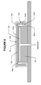
FIGS. 4-A through 4-C are diagrammatic illustrations showing various stages in another exemplary process for applying a decorative film or laminate to a part according to another embodiment of the present inventive subject matter.
FIG. 5 is diagrammatic illustration showing a cross-section view of an exemplary part having a peripheral lip which is suited to application of a decorative film or laminate in accordance with an embodiment of the present inventive subject matter.
FIG. 6 is diagrammatic illustrations showing another exemplary process in accordance with aspects of the present inventive subject matter for applying a decorative film or laminate to the part shown in FIG. 5.
DETAILED DESCRIPTION OF THE EMBODIMENT(S)
For clarity and simplicity, the present specification shall refer to structural and/or functional elements, relevant standards and/or protocols, and other components that are commonly known in the art without further detailed explanation as to their configuration or operation except to the extent they have been modified or altered in accordance with and/or to accommodate the preferred embodiment(s) presented herein.
With reference now to FIG. 1-A, in one suitable embodiment, a suitable decorative film or laminate is manufactured by providing a first carrier layer 10 which carries a protective layer 12. For example, suitably the protective layer 12 is a PVDF (Polyvinylidene Fluoride) film or other like film exhibiting high weatherability or similar protective properties and the carrier layer 10 is a polyester film or polyethylene terephthalate (PET). In one exemplary embodiment, an approximately 1 mil thick PVDF film is top coat extruded to an approximately 2 mil thick PET film. In another exemplary embodiment, an approximately 1 mil thick PVDF film is solvent coated or cast onto an approximately 2 mil thick PET film.
As shown in FIG. 1-B, an embossing layer 20 is then applied to the protective layer 12. Suitably, a primer coat or the like of acrylic or another suitable resin is applied to the protective layer 12, e.g., via a gravure press, and dried to form the embossing layer 20. In one exemplary embodiment, the coat weight for forming the embossing layer 20 is about 3 g/m2 and the coating may optionally be clear or tinted.
With reference now to FIG. 1-C, a desired design is then embossed into a surface 22 of the embossing layer 20, thereby selectively forming a pattern of raised portions (i.e., peaks and/or ridges) 22 a and lowered portions (i.e., depressions and/or valleys) 22 b in the surface 22. The embossed design, e.g., may optionally be patterned to produce a desired holographic or other like image or effect in the finished decoration.
Next, with reference to FIG. 1-D, an optional thin metallization layer 30 is applied to the embossed surface 22 of the embossing layer 20. For example, the metallization layer 30 is optionally created by vapor deposition of a thin layer of aluminum (Al) or other like metal or metal alloy on the surface 22. Suitably, the metallization layer 30 is less than or equal to about 320 angstroms in thickness. In one exemplary embodiment, the thickness of the metallization layer 30 is less than or equal to about 320 angstroms and greater than or equal to about 70 angstroms. In yet another embodiment, the thickness of the metallization layer 30 is less than or equal to about 160 angstroms and greater than or equal to about 75 angstroms. In still a further embodiment, the metallization layer 30 is less than or equal to about 140 angstroms and greater than or equal to about 90 angstroms. Suitably, e.g., as measured on a RD914 Macbeth density reading machine, the metallization layer 30 has an optical density of less than or equal to about 1.0 and greater than or equal to about 0.2. In another exemplary embodiment, the metallization layer 30 has an optical density less than or equal to about 0.75 and greater than or equal to about 0.3, and in still another embodiment less than or equal to 0.6 and greater than or equal to about 0.4.
As shown in FIG. 1-E, one or more primer coats of acrylic or another suitable resin are applied to the metallization layer 30 and dried to build up a layer 32 covering the metallization layer 30. In one exemplary embodiment, these coats are applied with a gravure press or the like. Suitably, two such primer coats are employed to build up the desired thickness of the layer 32, e.g., each coat being applied at a coat weight of about 3 g/m2. The primer coats may be chosen for their material characteristics, including but not limited to processing temperature lower than the softening point of the embossing surface 22 and/or for adhesion to subsequent layers, e.g., such as ABS (Acrylonitrile Butadiene Styrene) or metals.
With reference now to FIG. 1-F, the construction from FIG. 1-E is then laminated to a substrate 40 of thermoformable material, e.g., such as ABS. Suitably, the lamination is executed with heat and pressure to join the construction from FIG. 1-E to a 20 mil thickness of ABS thereby completing the final laminate construction 50.
The finished construction illustrated in FIG. 1-F is suitable for thermoforming into a three-dimensional (3D) or other desired shape. Importantly, the holographic or other like effect produced on the embossed surface 22 is not significantly degraded by the thermoforming process. Notably, this lack of significant degradation can be attributed at least in part to having a sufficiently thin and/or uniform metallization layer 30. In contrast to a relatively thick metallization layer that would tend to break and/or crack upon being bent or otherwise formed into a 3D shape, a relatively thin metallization layer tends to break or crack less. Moreover, with a relatively thin metallization layer as proposed herein any breaks or cracks that do form as a result of the thermoforming process would tend to be relatively smaller and/or otherwise less apparent to the naked eye or similar detection means. Conversely, the lower limit on the thickness of the metallization layer 30 is also significant. That is to say, having a sufficiently thick metallization layer 30 is important to achieving the desired holographic image or effect. Should the thickness of the metallization layer 30 be too low, the holographic image or effect that is desired may not be suitably apparent. In another embodiment, the thermoforming layer is protected by encapsulation of other polymers which protect the embossing layer from deformation in subsequent processes.
In another embodiment, as illustrated in FIG. 2, a decorative laminate 60 is constructed of a base film 62, a decorative or ink layer 64 and an adhesive layer 66. For example, in one exemplary embodiment, the base film 62 is made from an acrylic, nylon, olefin or optionally any other suitable thermoformable material. This film may optionally be micro-perforated to allow for air egress. A desired design or pattern, e.g., of one or more inks, is printed or otherwise applied, e.g., via a gravure press, to the base film 62 and dried to form the decorative layer 64. Thereafter, the adhesive layer 66 is coated on top of the decorative layer 64 and dried. Suitably, the adhesive forming the adhesive layer 66 is a PSA (Pressure Sensitive Adhesive) or a heat activated adhesive, and may be, e.g., a polyurethane based adhesive. Optionally the adhesive layer may be patterned to allow for air egress. In this way, the laminate 60 is thus constructed.
In yet another suitable embodiment, the decorative layer 64 may comprise one or more of the layers from the laminate construction 50. For example, any one or more of layers 20 through 32 may be used to create a decorative laminate 60 with a holographic or other like image or effect.
Suitably, a film or laminate, e.g., such as the laminate 50 or 60, is used to decorate one or more distinct sides of a multi-surface 3D part. Each surface or side may be a substantially planar surface, a curved surface, a complex-curved surface (i.e., curving in more than one direction of curvature) or a combination thereof. Optionally, the part may be a magnesium alloy or other metal part, e.g., such as the cover or case of a laptop computer or cover or housing for some other electronic device. In one exemplary embodiment, a laminate, e.g., such a the laminate 50, is first thermoformed, e.g., via a mold, to match the desired shape and/or surface of the part being decorated. Alternately, a film or laminate, e.g., such as the laminate 60, is applied using one or more of the techniques described below. It is to be appreciated, however, that while the laminates 50 and 60 have been illustrated and referenced in connection with the foregoing described embodiments, other similar laminate constructions and/or films may likewise be used in accordance with the described methods and/or processes that follow.
For example, FIG. 3-A shows a decorative laminate or film 70 being stretched or otherwise held over and/or slightly above a part 80 which is to be decorated. Suitably, the laminate or film 70 may have a construction similar to that of laminate 60. In the illustrated embodiment, the part 80 rests or is held on a raised work platform or pedestal 90.
As illustrated, a heater 92 applies heat to the laminate/film 70, e.g., to soften the same thereby allowing it to better conform to the part 80 and/or to activate an optionally heat activated adhesive on the side of the laminate/film 70 facing the part 80. Optionally, the surface or surfaces of the part 80 to be decorated are primed with epoxy or the like to facilitate bonding or adhering of the decoration laminate/film 70 to the primed surfaces. In one exemplary embodiment, the part 80 may be hot or heated to provide and/or assist in the above mentioned softening of the laminate/film 70 and/or activation of the adhesive.
In a next step, a nozzle 93 of a blower (not shown) is brought into close proximity of the laminate/film 70, e.g., as shown in FIG. 3-B. Suitably, the nozzle 93 is centrally positioned relative to a top surface 80 a of the part 80. The blower is then activated to blow compressed air from the nozzle 93 onto the laminate/film 70 thereby urging a central area or region of the laminate/film 70 into contact with the top surface 80 a of the part 80. Suitably, due to the relative closeness of the nozzle 93 to the laminate/film 70 and/or the part 80, the jet of compressed air therefrom acts primarily only on the central area or region of the top surface 80 a and not at the periphery thereof. That is to say, due at least in part to the relative proximity of the nozzle 93, the pressure from the air flow is initially constrained to a central area or region so that a middle portion of the laminate/film 70 is urged or forced into contact with the top surface 80 a of the part 80 while at a periphery the laminate/film 70 remains spaced apart from the top surface 80 a of the part 80.
As shown in FIG. 3-C, the nozzle 93 is then progressively withdrawn or moved away from the laminate/film 70. Accordingly, the effective pressure of the air flow from the nozzle 93 progressively spreads laterally outward from the central area or region to thereby progressively urge or force the laminate/film 70 at a periphery region into contact with the top surface 80 a of the part 80. In this manner, the laminate/film 70 is first contacted with the central area or region of the top surface 80 a of the part 80, and then moving laterally outward therefrom toward the periphery of the top surface 80 a of the part 80, the laminate/film 70 is progressively brought into contact with the top surface 80 a of the part 80. Accordingly, entrapment of air pockets or air bubbles between the laminate/film 70 and the top surface 80 a of the part 80 is minimized insomuch as the laminate/film 70 is applied from the inside-out thereby leaving an avenue open for air egress from between the laminate/film 70 and the top surface 80 a of the part 80.
Finally, as shown in FIG. 3-D, a vacuum is drawn via vacuum channels 94 arranged at or near a base of the pedestal 90. Accordingly, the laminate/film 70 is drawn around the sides or edge surfaces 80 b and onto the underside or bottom surface 80 c of the part 80 thereby contacting the same. In this manner, the laminate/film 70 is wrapped 180 degrees around the part 80 and adhered to multiple surfaces (i.e., surfaces 80 a, 80 b and 80 c) of the part 80.
FIGS. 4-A through 4-C illustrate yet another exemplary embodiment for applying the decorative laminate/film 70 to the part 80. In this embodiment, a press roller 96 is used to apply the laminate/film 70 to the top surface 80 a of the part 80. More specifically, FIG. 4-A shows the decorative laminate or film 70 being stretched or otherwise held over and/or slightly above the part 80 which is to be decorated. Suitably, the laminate or film 70 may have a construction similar to that of laminate 60. In the illustrated embodiment, the part 80 rests or is held on the raised work platform or pedestal 90.
As illustrated, the heater 92 applies heat to the laminate/film 70, e.g., to soften the same thereby allowing it to better conform to the part 80 and/or to activate an optionally heat activated adhesive on the side of the laminate/film 70 facing the part 80. Optionally, the surface or surfaces of the part 80 to be decorated are primed with epoxy or the like to facilitate bonding or adhering of the decoration laminate/film 70 to the primed surfaces. In one exemplary embodiment, the part 80 may be hot or heated to provide and/or assist in the above mentioned softening of the laminate/film 70 and/or activation of the adhesive.
In a next step, the roller 96 is brought into contact with the laminate/film 70, e.g., as shown in FIG. 4-B. Suitably, the roller 96 urges or forces the laminate/film 70 into contact with the top surface 80 a of the part 80 along a first edge thereof while leaving the rest of the laminate/film 70 spaced apart from the remainder of the top surface 80 a of the part 80. The roller 96 is then advanced, e.g., in the direction indicated by the arrow 96 a, relative to the laminate/film 70 and/or top surface 80 a of the part 80, thereby urging and/or forcing the rest of the laminate/film 70 into contact with the remainder of the top surface 80 a of the part 80, e.g., as seen in FIG. 4-C. In this manner, the laminate/film 70 is first contacted with one edge of the top surface 80 a of the part 80, and then moving laterally therefrom toward the opposite edge of the top surface 80 a of the part 80, the laminate/film 70 is progressively brought into contact with the top surface 80 a of the part 80. Accordingly, entrapment of air pockets or air bubbles between the laminate/film 70 and the top surface 80 a of the part 80 is again minimized insomuch as the laminate/film 70 is applied from one edge to the other thereby leaving an avenue open for air egress from between the laminate/film 70 and the top surface 80 a of the part 80.
Finally, as shown in FIG. 4-C, a vacuum is drawn via the vacuum channels 94 arranged at or near the base of the pedestal 90. Accordingly, the laminate/film 70 is drawn around the sides or edge surfaces 80 b and onto the underside or bottom surface 80 c of the part 80 thereby contacting the same. In this manner, the laminate/film 70 is wrapped 180 degrees around the part 80 and adhered to multiple surfaces (i.e., surfaces 80 a, 80 b and 80 c) of the part 80.
FIG. 5 shows an alternate configuration of the part being decorated, which has been re-number for purposes of this example but is nonetheless similar to the part 80 except as otherwise noted. In this case, the part 100 has a lip 104 at its edge or periphery. In particular, the part 100 has a top portion 102 (including an upper surface 102 a and a lower surface 102 b) that is bounded by the lip 104 at the periphery thereof. As shown, the lip 104 is defined by a wall which extends essentially transverse from the top portion 102 and includes an exterior facing surface 104 a and an interior facing surface 104 c that are joined by a lower edge surface 104 b. As is to be appreciated, it is at times desirable to decorate all four surfaces (i.e., surfaces 102 a, 104 a, 104 b and 104 c) by wrapping a suitable laminate and/or film (e.g., the laminate/film 70) 270 degrees around the part 100. In this case, the pedestal and/or vacuum arrangement is altered from that illustrated in FIGS. 3 and 4. More specifically, as shown in FIG. 6, the vacuum channels 94 now extend up through the pedestal 90 and out to openings 94 a arranged about the periphery of the pedestal 90 at or near a top portion thereof upon which the part 100 is held and/or otherwise supported. Notably, the lip 104 of the part 100 extends below the openings 94 a. Accordingly, when a vacuum is drawn through the channels 94, the laminate/film 70 is drawn up and into contact with the surface 104 c.
In practice, the laminate/film 70 is optionally first brought into contact with and/or adhered to the top surface 102 a of the part 100 in essentially the same manner as previously described with reference to FIGS. 3 and/or 4. A vacuum is then drawn through the vacuum channels 94. Accordingly, the laminate/film 70 is pulled down over the outer surface 104 a of the lip 104, across the lower edge surface 104 b and up the inside surface 104 c, making contact with and/or adhering to each surface in turn. In this manner, the laminate or film 70 is wrapped 270 degrees around and adhered to multiple surfaces (namely, surfaces 102 a, 104 a, 104 b and 104 c) of the part 100.
In any event, it is to be appreciated that in connection with the particular exemplary embodiment(s) presented herein certain structural and/or function features are described as being incorporated in defined elements and/or components. However, it is contemplated that these features may, to the same or similar benefit, also likewise be incorporated in other elements and/or components where appropriate. It is also to be appreciated that different aspects of the exemplary embodiments may be selectively employed as appropriate to achieve other alternate embodiments suited for desired applications, the other alternate embodiments thereby realizing the respective advantages of the aspects incorporated therein.
It is also to be appreciated that certain elements described herein as incorporated together may under suitable circumstances be stand-alone elements or otherwise divided. Similarly, a plurality of particular functions described as being carried out by one particular element may be carried out by a plurality of distinct elements acting independently to carry out individual functions, or certain individual functions may be split-up and carried out by a plurality of distinct elements acting in concert. Alternately, some elements or components otherwise described and/or shown herein as distinct from one another may be physically or functionally combined where appropriate.
In short, the present specification has been set forth with reference to preferred embodiments. Obviously, modifications and alterations will occur to others upon reading and understanding the present specification. It is intended that the invention be construed as including all such modifications and alterations insofar as they come within the scope of the appended claims or the equivalents thereof.

Claims (22)

What is claimed is:
1. A method for applying a decorative laminate construction to a part, said method comprising:
(a) supporting a part on a work surface;
(b) supporting a decorative laminate construction adjacent a first surface of the part without contacting the part;
(c) forcing the decorative laminate construction into contact with a first portion of the first surface of the part while a remaining portion of the first surface of the part is not contacted by the decorative laminate construction by arranging a nozzle next to a localized portion of the decorative laminate construction which corresponds to the first portion of the first surface of the part, and blowing air through the nozzle at the decorative laminate construction such that the localized portion of the decorative laminate construction is forced into contact with the first portion of the first surface of the part;
(d) progressively contacting the remaining portion of the first surface of the part with the decorative laminate construction by progressively increasing a relative distance between the nozzle and the decorative laminate construction while continuing to blow air through the nozzle such that an effective force of the blowing air progressively spreads to a wider area across the decorative laminate construction; and,
(e) wrapping the decorative laminate construction around an edge of the part to contact a second surface of the part with the decorative laminate construction, said second surface being different from the first surface.
2. The method of claim 1, further comprising:
(f) wrapping the decorative laminate construction further around another edge of the part to contact a third surface of the part with the decorative laminate construction, said third surface being different from the first and second surfaces.
3. The method of claim 2, further comprising:
(g) wrapping the decorative laminate construction further around yet another edge of the part to contact a fourth surface of the part with the decorative laminate construction, said fourth surface being different from the first, second and third surfaces.
4. The method of claim 3, wherein steps (e)-(g) are performed by creating a vacuum which pulls the decorative laminate construction around the part.
5. The method claim 1, further comprising:
heating at least one of the part and the decorative laminate construction.
6. The method of claim 1, wherein the decorative laminate construction comprises:
a protective layer, said protective layer comprising a film having opposing first and second major surfaces;
an embossing layer formed over the second major surface of the protective layer, said embossing layer have opposing first and second major surfaces, said first major surface of the embossing layer being proximate the protective layer and said second major surface of the embossing layer being distal from the protective layer, said second major surface of the embossing layer being embossed with a pattern such that features are produced on the second major surface of the embossed layer which are raised and lowered relative to one another;
a metallization layer formed over the second major surface of the embossing layer so as to achieve a visual effect by virtue of the metallization layer conforming to the features of the embossed pattern;
a primer layer formed over the metallization layer on a side thereof opposite the embossing layer; and
a carrier layer that carries the protective layer thereon such that the first major surface of the protective layer is in physical contact with the carrier layer and the second major surface of the protective layer is distal from the carrier layer.
7. The method of claim 6, wherein the protective layer is a polyvinylidene fluoride film.
8. The method of claim 6, wherein the embossing layer is formed from an acrylic resin.
9. The method of claim 6, wherein the primer layer is formed from an acrylic resin.
10. The method of claim 6, wherein the metallization layer is formed from aluminum.
11. The method of claim 6, wherein the metallization layer has a substantially uniform thickness less than or equal to 320 angstroms.
12. The method of claim 6, wherein the metallization layer has a substantially uniform thickness less than or equal to 160 angstroms and greater than or equal to 75 angstroms.
13. The method of claim 6, wherein the metallization layer has a substantially uniform thickness less than or equal to 140 angstroms and greater than or equal to 90 angstroms.
14. The method of claim 6, wherein the metallization layer has an optical density less than or equal to 1.0 and greater than or equal to 0.2.
15. The method of claim 6, wherein the metallization layer has an optical density less than or equal to 0.75 and greater than or equal to 0.3.
16. The method of claim 6, wherein the metallization layer has an optical density less than or equal to 0.6 and greater than or equal to 0.4.
17. The method claim 6, wherein the visual effect is a holographic effect.
18. The method of claim 6, further comprising:
a thermoforming layer formed over the primer layer on a side thereof opposite the metallization layer.
19. The method of claim 18, wherein the thermoforming layer is formed from acrylonitrile butadiene styrene.
20. The method of claim 6, wherein the carrier layer is a polyester or polyethylene terephthalate film.
21. The method of claim 6, further comprising:
an adhesive layer formed on a backside of the laminate construction.
22. The method of claim 21, wherein the adhesive layer is formed from a pressure sensitive adhesive or a heat activated adhesive.
US13/509,377 2009-11-16 2010-11-16 Method of application of a decoration film Expired - Fee Related US9908309B2 (en)

Priority Applications (1)

Application Number Priority Date Filing Date Title
US13/509,377 US9908309B2 (en) 2009-11-16 2010-11-16 Method of application of a decoration film

Applications Claiming Priority (3)

Application Number Priority Date Filing Date Title
US26153609P 2009-11-16 2009-11-16
US13/509,377 US9908309B2 (en) 2009-11-16 2010-11-16 Method of application of a decoration film
PCT/US2010/056858 WO2011060425A1 (en) 2009-11-16 2010-11-16 Decoration film and method of application

Publications (2)

Publication Number Publication Date
US20120222803A1 US20120222803A1 (en) 2012-09-06
US9908309B2 true US9908309B2 (en) 2018-03-06

Family

ID=43569275

Family Applications (1)

Application Number Title Priority Date Filing Date
US13/509,377 Expired - Fee Related US9908309B2 (en) 2009-11-16 2010-11-16 Method of application of a decoration film

Country Status (3)

Country Link
US (1) US9908309B2 (en)
CN (1) CN102712166A (en)
WO (1) WO2011060425A1 (en)

Families Citing this family (4)

* Cited by examiner, † Cited by third party
Publication number Priority date Publication date Assignee Title
US9044898B2 (en) 2012-04-03 2015-06-02 Apple Inc. Methods for joining electronic device housing structures using heat activated thermoset film
US10315399B2 (en) 2013-12-31 2019-06-11 Entrotech, Inc. Methods for application of polymeric film and related assemblies
US10162090B1 (en) 2018-02-20 2018-12-25 3M Innovative Properties Company Conformable reflective film having specified reflectivity when stretched at room temperature
WO2020101648A1 (en) * 2018-11-13 2020-05-22 Hewlett-Packard Development Company, L.P. Decorative films for covers of electronic devices

Citations (15)

* Cited by examiner, † Cited by third party
Publication number Priority date Publication date Assignee Title
US4838973A (en) * 1986-07-02 1989-06-13 General Motors Corporation Method of applying painted carrier films to automobile body parts
US5080742A (en) * 1988-09-30 1992-01-14 Tama Kasei Co., Ltd. Process for manufacture of article having embossed plastic sheet covering
US5641379A (en) * 1994-04-18 1997-06-24 Cesano; Franco Apparatus for producing a thermoplastic article having an undercut cross-section
US6264782B1 (en) * 1995-05-18 2001-07-24 Dai Nippon Printing Co., Ltd. Print with hologram and process for producing the same
US20020003635A1 (en) 2000-04-19 2002-01-10 Boswell David R. Holographic foil and method
US20020018880A1 (en) * 2000-08-01 2002-02-14 Young Robert P. Stamping foils for use in making printed circuits and radio frequency antennas
US20030107709A1 (en) * 2001-07-31 2003-06-12 Rodick Ronald G. Conformable holographic labels
US20030129343A1 (en) * 2002-01-10 2003-07-10 3M Innovative Properties Company Microstructured release liner
US20030203230A1 (en) 1999-03-30 2003-10-30 Pellingra Salvatore J. Polyolefin film with embossed surface
US20040219366A1 (en) * 2003-05-02 2004-11-04 Johnson John R. Bright formable metalized film laminate
US20060057392A1 (en) * 2003-10-07 2006-03-16 Smillie Benjamin A Multi-layer sheet having a weatherable surface layer
US20080000583A1 (en) 2006-06-29 2008-01-03 3M Innovative Properties Company Adhering graphic films on irregular substrates
US20080063863A1 (en) * 2006-09-08 2008-03-13 Illinois Tool Works, Inc. Selectively metallized heat transfer label
WO2009026147A2 (en) 2007-08-21 2009-02-26 3M Innovative Properties Company Method of thermoforming a printed sheet having an adhesive layer
EP2163381A2 (en) 2008-09-12 2010-03-17 API Foils Limited Holographic film

Family Cites Families (1)

* Cited by examiner, † Cited by third party
Publication number Priority date Publication date Assignee Title
CN2855730Y (en) * 2005-10-21 2007-01-10 赵臣 Composite film used for decoration

Patent Citations (16)

* Cited by examiner, † Cited by third party
Publication number Priority date Publication date Assignee Title
US4838973A (en) * 1986-07-02 1989-06-13 General Motors Corporation Method of applying painted carrier films to automobile body parts
US5080742A (en) * 1988-09-30 1992-01-14 Tama Kasei Co., Ltd. Process for manufacture of article having embossed plastic sheet covering
US5641379A (en) * 1994-04-18 1997-06-24 Cesano; Franco Apparatus for producing a thermoplastic article having an undercut cross-section
US6264782B1 (en) * 1995-05-18 2001-07-24 Dai Nippon Printing Co., Ltd. Print with hologram and process for producing the same
US20030203230A1 (en) 1999-03-30 2003-10-30 Pellingra Salvatore J. Polyolefin film with embossed surface
US20020003635A1 (en) 2000-04-19 2002-01-10 Boswell David R. Holographic foil and method
US20020018880A1 (en) * 2000-08-01 2002-02-14 Young Robert P. Stamping foils for use in making printed circuits and radio frequency antennas
US20030107709A1 (en) * 2001-07-31 2003-06-12 Rodick Ronald G. Conformable holographic labels
US20050214558A1 (en) 2001-07-31 2005-09-29 Rodick Ronald G Conformable holographic labels
US20030129343A1 (en) * 2002-01-10 2003-07-10 3M Innovative Properties Company Microstructured release liner
US20040219366A1 (en) * 2003-05-02 2004-11-04 Johnson John R. Bright formable metalized film laminate
US20060057392A1 (en) * 2003-10-07 2006-03-16 Smillie Benjamin A Multi-layer sheet having a weatherable surface layer
US20080000583A1 (en) 2006-06-29 2008-01-03 3M Innovative Properties Company Adhering graphic films on irregular substrates
US20080063863A1 (en) * 2006-09-08 2008-03-13 Illinois Tool Works, Inc. Selectively metallized heat transfer label
WO2009026147A2 (en) 2007-08-21 2009-02-26 3M Innovative Properties Company Method of thermoforming a printed sheet having an adhesive layer
EP2163381A2 (en) 2008-09-12 2010-03-17 API Foils Limited Holographic film

Also Published As

Publication number Publication date
WO2011060425A1 (en) 2011-05-19
CN102712166A (en) 2012-10-03
US20120222803A1 (en) 2012-09-06

Similar Documents

Publication Publication Date Title
KR101496536B1 (en) Decorating sheet, decorated resin molded article and method for production thereof
WO2010030883A1 (en) Wrapped three-dimensional shaped article and process for its production
TWI325817B (en) Decorative sheet, molded article, motor vehicle, and production method of molded article
US9908309B2 (en) Method of application of a decoration film
JP7136764B2 (en) Transfer film, method of manufacturing transfer film, method of using transfer film, and method of coating components
CN101678647B (en) Process for producing electric wave-transparent transfer material
JP2011136458A (en) Method of manufacturing decorative molded article
JP4851307B2 (en) Sheet for simultaneous decorative decoration and method for producing decorative molded product using the same
JP4448540B2 (en) Molded article manufacturing method and motor vehicle
JPH0557786A (en) Vacuum press laminate molding method
US11364669B2 (en) Surface protection method and surface decoration method for body to be coated
CN102371797A (en) Metallic Body Transferring Decoration Method And Inflating Transferring Device
JP3762887B2 (en) Method for producing hairline decorative molded product
JP2004181722A (en) Method for manufacturing resin molded product
JP5134795B2 (en) Manufacturing method for simultaneously molded decorative molded products
JP4593325B2 (en) Resin molded product and manufacturing method thereof
JP5862032B2 (en) Manufacturing method of insert molding
JP5088860B2 (en) Sheet for simultaneous decorative decoration and method for producing decorative molded product using the same
JPH0456760B2 (en)
JPH08142598A (en) Metallic gloss transfer foil with formability
JP2979019B2 (en) Molding film and its manufacturing method
WO2016121212A1 (en) Method for producing thermosetting resin molded article
JP2002192533A (en) Mold for molding decorative sheet, decorative sheet, method for manufacturing molded decorative sheet, and method for manufacturing resin molded article with decorative sheet
KR20100014619A (en) Film and method for producing a film for applying lacquer and a decorative layer to an object

Legal Events

Date Code Title Description
AS Assignment

Owner name: AVERY DENNISON CORPORATION, CALIFORNIA

Free format text: ASSIGNMENT OF ASSIGNORS INTEREST;ASSIGNORS:YANG, HUIMIN;BUNCH, STEVEN R.;REEL/FRAME:025738/0807

Effective date: 20101129

AS Assignment

Owner name: CCL LABEL, INC., MASSACHUSETTS

Free format text: ASSIGNMENT OF ASSIGNORS INTEREST;ASSIGNOR:AVERY DENNISON CORPORATION;REEL/FRAME:032007/0092

Effective date: 20130701

STCF Information on status: patent grant

Free format text: PATENTED CASE

FEPP Fee payment procedure

Free format text: MAINTENANCE FEE REMINDER MAILED (ORIGINAL EVENT CODE: REM.); ENTITY STATUS OF PATENT OWNER: LARGE ENTITY

LAPS Lapse for failure to pay maintenance fees

Free format text: PATENT EXPIRED FOR FAILURE TO PAY MAINTENANCE FEES (ORIGINAL EVENT CODE: EXP.); ENTITY STATUS OF PATENT OWNER: LARGE ENTITY

STCH Information on status: patent discontinuation

Free format text: PATENT EXPIRED DUE TO NONPAYMENT OF MAINTENANCE FEES UNDER 37 CFR 1.362

FP Lapsed due to failure to pay maintenance fee

Effective date: 20220306