US9879390B2 - Road milling machine and method for measuring the milling depth - Google Patents
Road milling machine and method for measuring the milling depth Download PDFInfo
- Publication number
- US9879390B2 US9879390B2 US15/376,023 US201615376023A US9879390B2 US 9879390 B2 US9879390 B2 US 9879390B2 US 201615376023 A US201615376023 A US 201615376023A US 9879390 B2 US9879390 B2 US 9879390B2
- Authority
- US
- United States
- Prior art keywords
- milling
- self
- milling machine
- propelled road
- machine
- Prior art date
- Legal status (The legal status is an assumption and is not a legal conclusion. Google has not performed a legal analysis and makes no representation as to the accuracy of the status listed.)
- Active
Links
Images


Classifications
-
- E—FIXED CONSTRUCTIONS
- E01—CONSTRUCTION OF ROADS, RAILWAYS, OR BRIDGES
- E01C—CONSTRUCTION OF, OR SURFACES FOR, ROADS, SPORTS GROUNDS, OR THE LIKE; MACHINES OR AUXILIARY TOOLS FOR CONSTRUCTION OR REPAIR
- E01C23/00—Auxiliary devices or arrangements for constructing, repairing, reconditioning, or taking-up road or like surfaces
- E01C23/06—Devices or arrangements for working the finished surface; Devices for repairing or reconditioning the surface of damaged paving; Recycling in place or on the road
- E01C23/08—Devices or arrangements for working the finished surface; Devices for repairing or reconditioning the surface of damaged paving; Recycling in place or on the road for roughening or patterning; for removing the surface down to a predetermined depth high spots or material bonded to the surface, e.g. markings; for maintaining earth roads, clay courts or like surfaces by means of surface working tools, e.g. scarifiers, levelling blades
- E01C23/085—Devices or arrangements for working the finished surface; Devices for repairing or reconditioning the surface of damaged paving; Recycling in place or on the road for roughening or patterning; for removing the surface down to a predetermined depth high spots or material bonded to the surface, e.g. markings; for maintaining earth roads, clay courts or like surfaces by means of surface working tools, e.g. scarifiers, levelling blades using power-driven tools, e.g. vibratory tools
- E01C23/088—Rotary tools, e.g. milling drums
-
- E—FIXED CONSTRUCTIONS
- E01—CONSTRUCTION OF ROADS, RAILWAYS, OR BRIDGES
- E01C—CONSTRUCTION OF, OR SURFACES FOR, ROADS, SPORTS GROUNDS, OR THE LIKE; MACHINES OR AUXILIARY TOOLS FOR CONSTRUCTION OR REPAIR
- E01C23/00—Auxiliary devices or arrangements for constructing, repairing, reconditioning, or taking-up road or like surfaces
- E01C23/06—Devices or arrangements for working the finished surface; Devices for repairing or reconditioning the surface of damaged paving; Recycling in place or on the road
- E01C23/12—Devices or arrangements for working the finished surface; Devices for repairing or reconditioning the surface of damaged paving; Recycling in place or on the road for taking-up, tearing-up, or full-depth breaking-up paving, e.g. sett extractor
- E01C23/122—Devices or arrangements for working the finished surface; Devices for repairing or reconditioning the surface of damaged paving; Recycling in place or on the road for taking-up, tearing-up, or full-depth breaking-up paving, e.g. sett extractor with power-driven tools, e.g. oscillated hammer apparatus
- E01C23/127—Devices or arrangements for working the finished surface; Devices for repairing or reconditioning the surface of damaged paving; Recycling in place or on the road for taking-up, tearing-up, or full-depth breaking-up paving, e.g. sett extractor with power-driven tools, e.g. oscillated hammer apparatus rotary, e.g. rotary hammers
-
- G—PHYSICS
- G01—MEASURING; TESTING
- G01B—MEASURING LENGTH, THICKNESS OR SIMILAR LINEAR DIMENSIONS; MEASURING ANGLES; MEASURING AREAS; MEASURING IRREGULARITIES OF SURFACES OR CONTOURS
- G01B5/00—Measuring arrangements characterised by the use of mechanical techniques
- G01B5/18—Measuring arrangements characterised by the use of mechanical techniques for measuring depth
Definitions
- the invention refers to a self-propelled road milling machine, especially a cold milling machine, as well as a methods for measuring the milling depth.
- the machine frame is supported by a track assembly comprising wheels or caterpillar tracks connected to the machine frame through lifting columns, the lifting columns allowing to maintain the machine frame in a horizontal plane or in parallel to the ground or under a predetermined longitudinal and/or transversal inclination.
- a milling roll for working a ground or traffic surface is supported at the machine frame.
- height-adjustable side plates are provided as edge protectors at an outer wall of the road milling machine, which side plates, in operation, rest on the ground or traffic surface at the lateral non-milled edges of the milling track.
- a height-adjustable stripping means is provided which, in operation, may be lowered into the milling track formed by the milling roll to strip off milling material remaining in the milling track.
- the road milling machine has a control means for controlling the milling depth of the milling roll.
- the milling depth can not be controlled accurately enough and that, for this reason, the milling depth has to be measured repeatedly by hand during the milling operation.
- a hard traffic surface e.g. concrete
- the tools are worn heavily so that the milling depth set is corrupted by the decreasing diameter of the cutting circle.
- the wear of the tools when milling concrete, can cause a difference in the milling radius of 15 mm after only a few 100 m, so that the measuring of an adjustment of side plates, for example, with respect to the machine frame is not sufficiently accurate.
- the milling depth is insufficient, a time-consuming reworking of the milling track has to be carried out. Should the milling track be too deep, more building material has to be applied afterwards in order to achieve the desired ground or traffic surface level.
- the invention advantageously provides that at least one measuring means detects the lifting of a first sensor means resting on the ground or traffic surface and/or the lowering of a second sensor means to the bottom of the milling track, the lifting or lowering being effected in correspondence with the present milling depth. From the measured values supplied by the at least one measuring means, the control means can determine the milling depth at the level of the measuring means of the milling roll or the second sensor means.
- the measurement is effected preferably at the level of the stripping means arranged closely behind the milling roll, or immediately behind the stripping means, if a separate sensor means is provided.
- the stripping means as a sensor means is advantageous in that no measuring errors are caused by some unevenness in the milling track. It is another advantage that the stripping means is protected against wear at its bottom edge.
- control means can use the measurement values of the at least one measuring means to determine the current milling depth of the milling roll at the level of the milling roll axis. Preferably, this is done by a calculation that may also take into account an inclined position of the machine frame.
- the measuring means are preferably formed by position sensing means.
- the first sensor means is formed by at least one of the side plates arranged on either side at the front sides of the milling roll so as to be height-adjustable and pivotable with respect to the machine frame.
- the side plates rest on the ground or traffic surface or are pressed against these, so that a change of their position relative to the machine frame during operation allows for an exact detection of the milling depth, if a measurement of the change of the position of a second sensor means is performed additionally in the milling track relative to the machine frame.
- the measuring means may comprise cable lines coupled with the side plates and/or the stripping means, and associated cable-line sensors as the position sensors which measure the changes of the position of the side plates and the stripping means relative to the machine frame or the relative displacement of at least one of the side plates in relation to the stripping means or the second sensor means.
- the cable lines coupled with the side plates and the stripping means are arranged transversely to the milling track in a substantially vertical plane extending approximately at the level of the stripping means.
- a cable line is coupled on the one hand with the stripping means and, on the other hand, with at least one of the side plates via a guide roller, such that a cable-line sensor immediately measures the milling depth, e.g. at the guide roller.
- the side plate has a respective measuring means at the side edges facing the side plates, which measures the relative displacement of the stripping means with respect to the at least one adjacent side plate or the relative displacement of at least one side plate with respect to the stripping means.
- the stripping means may include at least one height-adjustable beam as the first sensing means, which is guided vertically and linearly in the stripping means and extends transversely to the travelling direction, said beam resting on the ground or traffic surface beside the milling track, the position of the beam relative to the stripping means, preferably with respect to height and/or inclination, being measurable by the measuring means.
- the side plates may rest on the edges of the ground or traffic surface beside the milling track milled by the milling machine, or they may alternatively be pressed on the edges by hydraulic means.
- the stripping means may also be pressed on the surface of the milling track using hydraulic means.
- the hydraulic means for pressing the side plates on the ground or traffic surface or for pressing the stripping means on the bottom of the milling track may comprise integrated position sensing systems.
- a plurality of, preferably two respective piston/cylinder units with integrated position sensing systems may be provided, whose position sensing signals are used by the control means to calculate the current milling depth from the relative difference between the positions of the stripping means and the at least one first sensor means.
- the control means that receives the position sensing signals from the measuring means is adapted to automatically control the lifted condition of the rear lifting columns, seen in the travelling direction, to establish parallelism between the machine frame and the ground or traffic surface at a desired milling depth.
- the side plates resting on the traffic surface so as to be pivotable with respect to the machine frame may comprise measuring means spaced apart in the travelling direction, the control means being capable to measure the longitudinal and/or the transversal inclination of the machine frame with respect to the ground or traffic surface from the difference between the measurement signals from the side plates and the stripping means.
- the front and/or rear lifting columns may include a position sensing system to detect the lifted condition.
- the control means that receives the position sensing signals from the measuring means can control the condition of all lifting columns such that the machine frame has a predetermined inclination or a predetermined travel-distance-dependent transverse inclination across the travelling direction.
- the current set value for the milling depth of the milling roll is adjusted using the front lifting columns.
- FIG. 1 shows a cold milling machine
- FIG. 2 illustrates a first sensor means attached to the stripping plate.
- FIG. 3 shows two piston/cylinder units for lifting or lowering the stripping plate of a stripping means.
- FIG. 4 illustrates an optical device for measuring the positional difference between the side plates and the stripping means.
- FIG. 5 shows a cable line measuring means provided between the side plates and the stripping means.
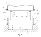
- FIG. 6 illustrates a preferred embodiment
- FIGS. 7 a, b, c are schematic illustrations of the measurement error occurring at the stripping plate of the stripping means in the absence of parallelism between the machine frame and the ground or traffic surface.
- the road milling machine illustrated in FIG. 1 comprises a machine frame 4 supported by a track assembly having two front chain tracks 2 and at least one rear chain track 3 .
- the chain tracks 2 , 3 are connected with the machine frame 4 via lifting columns 12 , 13 . It is understood that wheels may be used instead of the chain tracks 2 , 3 .
- the machine frame 4 can be lifted or lowered or moved to take a predetermined inclined position with respect to the ground or traffic surface 8 .
- the milling roll 6 supported in the machine frame 4 is enclosed by a roll case 9 which is open at the front, seen in the travelling direction, towards a conveyor belt 11 that conveys the milled material in a front part of the machine frame 4 to a second conveyor means 13 .
- the second conveyor means 13 with which the milled material may be delivered onto a truck, for example, is not fully illustrated in FIG. 1 because of its length.
- a height-adjustable stripping means 14 is arranged which, in operation, has a stripping plate 15 engage into the milling track 17 formed by the milling roll 6 and strip the bottom of the milling track 17 so that no milled material is left in the milling track 17 behind the stripping plate.
- a driver's stand 5 with a control panel for the vehicle operator is provided for all control functions of the driving and milling operations. It also includes a control means 23 for controlling the milling depth of the milling roll 6 .
- the side plates 10 arranged on either side near the front end of the milling roll 6 , and the stripping means 14 are provided with measuring means 16 that allow the determination of the current milling depth at the level of the stripping means 14 or the calculation of the milling depth at the level of the rotational axis of the milling roll.
- the milling depth is determined in a plane orthogonal to the ground or traffic surface, which plane is parallel to the rotational axis of the milling roll and includes the rotational axis.
- a first sensor means e.g. the side plates 10
- a second sensor means e.g. the stripping means
- Measuring means 16 preferably formed by position sensing means, measure the displacements of the sensor means, e.g. the side plates 10 or a beam 20 or the stripping plate 15 , with respect to the machine frame 4 or relative to each other.
- FIG. 2 shows a beam 20 as the sensor means, resting on the ground or traffic surface 8 and guided at the stripping plate 15 of the stripping means in a slot 24 extending linearly and orthogonally to the bottom edge 19 of the stripping plate 15 . It is understood that two mutually parallel slots 24 can be provided in the stripping plate 15 or that the beam 20 , serving as the sensing means, can be guided in a different manner so as to be height-adjustable at the stripping means 14 .
- the measuring means 16 provided in the form of a position sensing means, detects the displacement of the beam 20 with respect to the stripping means 14 .
- FIG. 3 illustrates another embodiment wherein the stripping plate 15 of the stripping means 14 can be lifted or lowered by means of hydraulic means.
- the hydraulic means are formed by piston/cylinder units 26 , 28 with an integrated position sensing system. This means that the piston/cylinder units 26 , 28 not only allow for the stroke movement of the stripping means, but moreover generate a position signal.
- the piston/cylinder units 26 , 28 have one end connected to the machine frame 4 and the other end connected to the stripping plate 15 .
- FIG. 4 illustrates an embodiment, wherein the relative movement between the side plates 10 and the stripping plate 15 is measured directly in order to detect the milling depth of the milling track 17 .
- elements 38 , 40 of the measuring means 16 are provided, e.g., at the side plates 10 and opposite thereto at the stripping plate 15 , which elements allow for the detection of the relative displacement of the stripping plate 15 with respect to the side plates 10 .
- This displacement corresponds to the milling depth s in FIG. 4 .
- such a measuring means, which measures relative displacements may be formed by an optical system, e.g. by reading a scale with an optical sensor, or by an electromagnetic or inductive system.
- the relative position sensing system between the side plates 10 and the stripping plate 15 may also be formed by a cable line 22 in combination with a cable-line sensor 21 .
- the cable line 22 is coupled with the stripping plate 15 of the stripping means 14 on the one hand and, on the other hand, with at least one of the side plates 10 via a guide roller 35 , so that the signal from the cable-line sensor 21 can immediately indicate the value of the current milling depth.
- the side plates 10 themselves can be used as first sensor means by monitoring their position with respect to the machine frame 4 or the second sensor means by means of a cable line and a cable-line sensor or by means of piston/cylinder units 30 , 32 with integrated position sensing means.
- the measuring means can also measure the displacement of the side plates 10 with respect to the machine frame 4 .
- two measuring means one in front of the side plates 10 and one behind the same, seen in the travelling direction, it is also possible to determine the longitudinal inclination of the machine frame 4 with respect to the ground or traffic surface 8 or to also determine the transverse inclination of the machine frame 4 by a comparison of the measured values for both side plates 10 on both sides of the milling roll 6 .
- FIG. 6 illustrates a preferred embodiment, wherein cable lines 22 comprising cable-line sensors 21 mounted to the machine frame 4 are arranged on both sides of the stripping means 15 .
- the side plates 10 are also provided with cable lines 22 and cable-line sensors 21 fastened at the machine frame 4 .
- the milling depth s is determined from the difference between the measured values of the cable-line sensors 21 for the side plates 10 and the cable-line sensors 21 of the stripping means 15 .
- the measurement should preferably be made in the same substantially vertical plane in order to avoid measurement errors.
- FIGS. 7 a to 7 c illustrate the cable-line sensors 21 for the side plates 10 and the stripping plates 14 , the drawings only indicating one cable-line sensor 21 , since the cable-line sensors are arranged one behind the other in substantially the same plane.
- FIGS. 7 a, b, c are to illustrate the case where the ground or traffic surface 8 is not parallel to the machine frame 4 , the measured milling depth value indicated by the measuring means having to be corrected because of an angle error, because a longitudinal inclination of the machine frame 4 corrupts the measurement signal at the level of the stripping plate 15 or a second sensor means near the stripping means 14 .
- Due to the fixed geometrical relations, i.e. the distance of the stripping plate 15 from the rotational axis of the milling roll 6 the measured milling depth value can be corrected, knowing the angular deviation from the horizontal in the travelling direction, and the current milling depth at the level of the milling roll axis can be calculated.
- the angular deviation in the travelling direction may be determined, for example, from the position of the lifting columns 12 , 13 of the caterpillar track assemblies 2 , 3 or the piston/cylinder units 30 , 32 .
- FIG. 7 c illustrates the position of the at least one side plate 10 for a ground-parallel position of the machine frame 4 .
- the stripping plate 15 illustrated in FIGS. 7 a to 7 c is located at the roll case 9 , so that the distance of the stripping plate 14 from the rotational axis to the milling roll 6 can be determined unambiguously in order to allow for a calculation of the milling depth correction should the machine frame 4 not be parallel to the ground.
- the control means 23 can calculate the current milling depth at the level of the milling roll axis from the position sensing signals received, and it can possibly also generate a control signal for a vertical adjustment of the milling roll 6 .
- control means 23 can automatically control the lifted condition of the at least one rear lifting column 13 , seen in the travelling direction, to establish parallelism between the machine frame 4 and the ground or traffic surface 8 or to the horizontal plane or to a predetermined desired milling plane.
Landscapes
- Engineering & Computer Science (AREA)
- Mining & Mineral Resources (AREA)
- Architecture (AREA)
- Civil Engineering (AREA)
- Structural Engineering (AREA)
- Mechanical Engineering (AREA)
- Physics & Mathematics (AREA)
- General Physics & Mathematics (AREA)
- Road Repair (AREA)
Abstract
Description
Claims (22)
Priority Applications (6)
| Application Number | Priority Date | Filing Date | Title |
|---|---|---|---|
| US15/376,023 US9879390B2 (en) | 2006-12-22 | 2016-12-12 | Road milling machine and method for measuring the milling depth |
| US15/625,266 US9879391B2 (en) | 2006-12-22 | 2017-06-16 | Road milling machine and method for measuring the milling depth |
| US15/880,165 US10458078B2 (en) | 2006-12-22 | 2018-01-25 | Road milling machine and method for measuring the milling depth |
| US16/659,616 US11008716B2 (en) | 2006-12-22 | 2019-10-22 | Road milling machine and method for measuring the milling depth |
| US17/313,337 US11655599B2 (en) | 2006-12-22 | 2021-05-06 | Road milling machine and method for measuring the milling depth |
| US18/299,761 US20230313471A1 (en) | 2006-12-22 | 2023-04-13 | Road Milling Machine and Method for Measuring the Milling Depth |
Applications Claiming Priority (7)
| Application Number | Priority Date | Filing Date | Title |
|---|---|---|---|
| DE102006062129.8 | 2006-12-22 | ||
| DE102006062129 | 2006-12-22 | ||
| DE102006062129A DE102006062129B4 (en) | 2006-12-22 | 2006-12-22 | Road construction machine and method for measuring the cutting depth |
| US12/003,094 US8246270B2 (en) | 2006-12-22 | 2007-12-20 | Road milling machine and method for measuring the milling depth |
| US13/557,729 US8807867B2 (en) | 2006-12-22 | 2012-07-25 | Road milling machine and method for measuring the milling depth |
| US14/341,191 US9523176B2 (en) | 2006-12-22 | 2014-07-25 | Road milling machine and method for measuring the milling depth |
| US15/376,023 US9879390B2 (en) | 2006-12-22 | 2016-12-12 | Road milling machine and method for measuring the milling depth |
Related Parent Applications (1)
| Application Number | Title | Priority Date | Filing Date |
|---|---|---|---|
| US14/341,191 Continuation US9523176B2 (en) | 2006-12-22 | 2014-07-25 | Road milling machine and method for measuring the milling depth |
Related Child Applications (2)
| Application Number | Title | Priority Date | Filing Date |
|---|---|---|---|
| US15/625,266 Continuation US9879391B2 (en) | 2006-12-22 | 2017-06-16 | Road milling machine and method for measuring the milling depth |
| US15/880,165 Continuation US10458078B2 (en) | 2006-12-22 | 2018-01-25 | Road milling machine and method for measuring the milling depth |
Publications (2)
| Publication Number | Publication Date |
|---|---|
| US20170275832A1 US20170275832A1 (en) | 2017-09-28 |
| US9879390B2 true US9879390B2 (en) | 2018-01-30 |
Family
ID=39183184
Family Applications (9)
| Application Number | Title | Priority Date | Filing Date |
|---|---|---|---|
| US12/003,094 Active 2030-08-14 US8246270B2 (en) | 2006-12-22 | 2007-12-20 | Road milling machine and method for measuring the milling depth |
| US13/557,729 Active US8807867B2 (en) | 2006-12-22 | 2012-07-25 | Road milling machine and method for measuring the milling depth |
| US14/341,191 Active US9523176B2 (en) | 2006-12-22 | 2014-07-25 | Road milling machine and method for measuring the milling depth |
| US15/376,023 Active US9879390B2 (en) | 2006-12-22 | 2016-12-12 | Road milling machine and method for measuring the milling depth |
| US15/625,266 Active US9879391B2 (en) | 2006-12-22 | 2017-06-16 | Road milling machine and method for measuring the milling depth |
| US15/880,165 Active US10458078B2 (en) | 2006-12-22 | 2018-01-25 | Road milling machine and method for measuring the milling depth |
| US16/659,616 Active US11008716B2 (en) | 2006-12-22 | 2019-10-22 | Road milling machine and method for measuring the milling depth |
| US17/313,337 Active 2028-03-14 US11655599B2 (en) | 2006-12-22 | 2021-05-06 | Road milling machine and method for measuring the milling depth |
| US18/299,761 Pending US20230313471A1 (en) | 2006-12-22 | 2023-04-13 | Road Milling Machine and Method for Measuring the Milling Depth |
Family Applications Before (3)
| Application Number | Title | Priority Date | Filing Date |
|---|---|---|---|
| US12/003,094 Active 2030-08-14 US8246270B2 (en) | 2006-12-22 | 2007-12-20 | Road milling machine and method for measuring the milling depth |
| US13/557,729 Active US8807867B2 (en) | 2006-12-22 | 2012-07-25 | Road milling machine and method for measuring the milling depth |
| US14/341,191 Active US9523176B2 (en) | 2006-12-22 | 2014-07-25 | Road milling machine and method for measuring the milling depth |
Family Applications After (5)
| Application Number | Title | Priority Date | Filing Date |
|---|---|---|---|
| US15/625,266 Active US9879391B2 (en) | 2006-12-22 | 2017-06-16 | Road milling machine and method for measuring the milling depth |
| US15/880,165 Active US10458078B2 (en) | 2006-12-22 | 2018-01-25 | Road milling machine and method for measuring the milling depth |
| US16/659,616 Active US11008716B2 (en) | 2006-12-22 | 2019-10-22 | Road milling machine and method for measuring the milling depth |
| US17/313,337 Active 2028-03-14 US11655599B2 (en) | 2006-12-22 | 2021-05-06 | Road milling machine and method for measuring the milling depth |
| US18/299,761 Pending US20230313471A1 (en) | 2006-12-22 | 2023-04-13 | Road Milling Machine and Method for Measuring the Milling Depth |
Country Status (7)
| Country | Link |
|---|---|
| US (9) | US8246270B2 (en) |
| EP (2) | EP2738309B1 (en) |
| JP (1) | JP4940445B2 (en) |
| CN (2) | CN201187026Y (en) |
| AU (1) | AU2007249060B2 (en) |
| BR (1) | BRPI0705796B1 (en) |
| DE (1) | DE102006062129B4 (en) |
Cited By (7)
| Publication number | Priority date | Publication date | Assignee | Title |
|---|---|---|---|---|
| WO2020086577A1 (en) | 2018-10-23 | 2020-04-30 | Caterpillar Paving Products Inc. | Inclination control for construction machines |
| US11255059B2 (en) | 2020-01-28 | 2022-02-22 | Caterpillar Paving Products Inc. | Milling machine having a non-contact leg-height measurement system |
| US11566387B2 (en) | 2020-03-12 | 2023-01-31 | Caterpillar Paving Products Inc. | Relative velocity based actuator velocity calibration system |
| US11578737B2 (en) | 2020-03-12 | 2023-02-14 | Caterpillar Paving Products Inc. | Distance based actuator velocity calibration system |
| US11629735B2 (en) | 2020-01-28 | 2023-04-18 | Caterpillar Paving Products Inc. | Milling machine having a fluid flow based height measurement system |
| US11692563B2 (en) | 2020-01-28 | 2023-07-04 | Caterpillar Paving Products Inc. | Milling machine having a valve current based height measurement system |
| US11746482B2 (en) | 2018-10-23 | 2023-09-05 | Caterpillar Paving Products Inc. | Inclination control for construction machines |
Families Citing this family (98)
| Publication number | Priority date | Publication date | Assignee | Title |
|---|---|---|---|---|
| DE102005044211A1 (en) | 2005-09-12 | 2007-03-22 | Wirtgen Gmbh | Self-propelled construction machine, as well as lifting column for a construction machine |
| DE102006020293B4 (en) | 2006-04-27 | 2013-07-11 | Wirtgen Gmbh | Road construction machine, leveling device and method for controlling the cutting depth or milling inclination in a road construction machine |
| EP2650443B1 (en) * | 2006-12-22 | 2021-06-30 | Wirtgen GmbH | Road milling machine with control means for producing parallelism of the machine frame with the ground |
| DE102006062129B4 (en) | 2006-12-22 | 2010-08-05 | Wirtgen Gmbh | Road construction machine and method for measuring the cutting depth |
| EP2199466B1 (en) * | 2008-12-16 | 2011-07-13 | Joseph Vögele AG | Method for laying a paving surface |
| US8142103B2 (en) * | 2009-02-20 | 2012-03-27 | Caterpillar Trimble Control Technologies Llc | Wireless sensor with kinetic energy power arrangement |
| US8469456B2 (en) | 2009-03-25 | 2013-06-25 | Wirtgen Gmbh | Ejector unit for a road milling machine or the like |
| DE102009014730B3 (en) * | 2009-03-25 | 2010-10-28 | Wirtgen Gmbh | Ejector or ejector unit for a road milling machine or the like |
| DE102009041842A1 (en) * | 2009-09-18 | 2011-09-01 | Wirtgen Gmbh | Self-propelled road milling machine |
| CN102213955B (en) * | 2010-04-01 | 2012-10-10 | 常州机械电子工程研究所 | General building machine control system |
| DE102010015173A1 (en) * | 2010-04-16 | 2011-10-20 | Bomag Gmbh | Method for operating a ground milling machine with a height-adjustable milling drum |
| DE102010022467B4 (en) | 2010-06-02 | 2014-12-04 | Wirtgen Gmbh | Road construction machine, and method for controlling the distance of a road construction machine moving on a ground surface |
| KR101048844B1 (en) * | 2011-01-31 | 2011-07-13 | 주식회사 코로스 | Apparatus for grinding concrete pavement |
| US8794867B2 (en) | 2011-05-26 | 2014-08-05 | Trimble Navigation Limited | Asphalt milling machine control and method |
| DE102011106139B4 (en) * | 2011-06-10 | 2015-04-02 | Wirtgen Gmbh | Method and device for determining a surface milled by at least one construction machine or mining machine with a milling drum |
| CN102322015A (en) * | 2011-07-13 | 2012-01-18 | 三一重工股份有限公司 | Milling and planing machine and milling and planing machine control method |
| DE102011114710A1 (en) * | 2011-09-30 | 2013-04-04 | Bomag Gmbh | Side shield assembly for a milling device, use of a side shield assembly and milling device with a side shield assembly |
| US8899689B2 (en) * | 2011-12-21 | 2014-12-02 | Caterpillar Paving Products Inc. | Automatic cut-transition milling machine and method |
| US8820845B2 (en) | 2012-04-17 | 2014-09-02 | Schlumberger Technology Corporation | Sensored pick assembly |
| RU2500851C1 (en) * | 2012-05-24 | 2013-12-10 | Федеральное государственное бюджетное образовательное учреждение высшего профессионального образования "Тюменский государственный нефтегазовый университет" (ТюмГНГУ) | Device to form track strips in repair of motor roads |
| US9121148B2 (en) | 2012-05-25 | 2015-09-01 | Surface Preparation Technologies, Llc | Method and apparatus for cutting grooves in a road surface |
| DE102012012397A1 (en) * | 2012-06-25 | 2014-04-24 | Wirtgen Gmbh | Self-propelled construction machine |
| DE102012015346A1 (en) | 2012-08-06 | 2014-02-20 | Wirtgen Gmbh | Self-propelled construction machine |
| DE102012016173A1 (en) | 2012-08-16 | 2014-02-20 | Wirtgen Gmbh | Self-propelled construction machine and method for operating a construction machine |
| DE102012215013A1 (en) | 2012-08-23 | 2014-02-27 | Wirtgen Gmbh | Self-propelled milling machine, as well as method for unloading milled material |
| US9121146B2 (en) | 2012-10-08 | 2015-09-01 | Wirtgen Gmbh | Determining milled volume or milled area of a milled surface |
| DE102012020655A1 (en) | 2012-10-19 | 2014-04-24 | Wirtgen Gmbh | Self-propelled construction machine |
| US8764118B1 (en) | 2012-12-14 | 2014-07-01 | Caterpillar Paving Products Inc. | Sensor mounting system for road milling machine |
| BE1021123B1 (en) * | 2013-01-14 | 2015-12-14 | Cnh Industrial Belgium Nv | CALIBRATE A DISTANCE SENSOR ON AN AGRICULTURAL VEHICLE |
| US9641806B2 (en) | 2013-03-12 | 2017-05-02 | 3M Innovative Properties Company | Average speed detection with flash illumination |
| US9096977B2 (en) | 2013-05-23 | 2015-08-04 | Wirtgen Gmbh | Milling machine with location indicator system |
| DE102013010298A1 (en) * | 2013-06-19 | 2014-12-24 | Bomag Gmbh | Construction machine, in particular road milling machine, and method for compensating for uneven floors for such a construction machine |
| DE102013013967A1 (en) * | 2013-08-23 | 2015-03-12 | Wirtgen Gmbh | Self-propelled construction machine and method for operating a self-propelled construction machine |
| US9574310B2 (en) | 2013-09-20 | 2017-02-21 | Surface Preparation Technologies Llc | Method and apparatus for cutting a sinusoidal groove in a road surface |
| DE112013000256T5 (en) * | 2013-09-27 | 2015-07-02 | Komatsu Ltd. | Measuring instrument for determining limit wear |
| DE102014005077A1 (en) | 2014-04-04 | 2015-10-08 | Wirtgen Gmbh | Self-propelled construction machine and method for controlling a self-propelled construction machine |
| USD755859S1 (en) * | 2014-08-12 | 2016-05-10 | Bomag Gmbh | Milling machine |
| US9475526B2 (en) * | 2014-08-23 | 2016-10-25 | Caterpillar Inc. | Track link having a wear sensing device |
| DE102014012831B4 (en) | 2014-08-28 | 2018-10-04 | Wirtgen Gmbh | Self-propelled construction machine and method for controlling a self-propelled construction machine |
| DE102014012825A1 (en) | 2014-08-28 | 2016-03-03 | Wirtgen Gmbh | Self-propelled construction machine and method for controlling a self-propelled construction machine |
| DE102014012836B4 (en) | 2014-08-28 | 2018-09-13 | Wirtgen Gmbh | Self-propelled construction machine and method for visualizing the processing environment of a construction machine moving in the field |
| DE102014017892B4 (en) | 2014-12-04 | 2019-03-21 | Wirtgen Gmbh | Self-propelled construction machine and method for operating a self-propelled construction machine |
| DE102014018082B4 (en) * | 2014-12-08 | 2020-03-19 | Bomag Gmbh | Method for controlling a construction machine, control system for a construction machine, and construction machine |
| DE102014019168A1 (en) | 2014-12-19 | 2016-06-23 | Bomag Gmbh | CONSTRUCTION MACHINE, PARTICULARLY ROAD TERMINAL, AND METHOD FOR COMPENSATING FLOOR INFLUENCE FOR SUCH A CONSTRUCTION MACHINE |
| US9631329B2 (en) | 2014-12-19 | 2017-04-25 | Wirtgen Gmbh | Frame distortion control |
| DK3292247T3 (en) * | 2015-01-18 | 2020-02-17 | Aquatec Iq Tech Gmbh | Milling machine for road surfaces or pavements |
| US20160326701A1 (en) * | 2015-05-07 | 2016-11-10 | Caterpillar Paving Products Inc. | Rotary Mixer with Automated Control Functions |
| DE102015212902A1 (en) | 2015-07-09 | 2017-01-12 | Wirtgen Gmbh | Milling machine for processing of ground surfaces, transfer device, and method for transferring milled material |
| US20170011564A1 (en) * | 2015-07-10 | 2017-01-12 | Caterpillar Paving Products Inc. | Cutting bit monitoring system |
| KR101690884B1 (en) * | 2015-07-20 | 2017-01-09 | 신요식 | Recylcing apparatus for polishing sand of playground and construction method using this |
| CN105335546B (en) * | 2015-09-08 | 2019-04-23 | 陕西高速机械化工程有限公司 | A kind of milling measurement method of maintenance of surface |
| DE102016113251A1 (en) | 2015-10-27 | 2017-04-27 | Wirtgen Gmbh | Milling machine and method for operating a milling machine |
| DE102015014573B4 (en) | 2015-11-12 | 2020-03-19 | Wirtgen Gmbh | Self-propelled milling machine and method for working a traffic area |
| US10724370B2 (en) | 2015-12-08 | 2020-07-28 | Kennametal Inc. | Smart cutting drum assembly |
| DE102016000594A1 (en) * | 2016-01-21 | 2017-07-27 | Volkmann & Rossbach Gmbh & Co. Kg | Module for covering vulnerable sections or elements on fixed surfaces |
| US20190249377A1 (en) * | 2016-06-16 | 2019-08-15 | R.W. Tomlinson Limited | Belted Compaction Apparatus Kit and Method |
| DE102017005814A1 (en) | 2016-06-21 | 2017-12-21 | Bomag Gmbh | Method for aligning a ground milling machine to the ground and ground milling machine |
| DE102016222589B4 (en) | 2016-11-16 | 2020-01-16 | Wirtgen Gmbh | Self-propelled milling machine and method for controlling a self-propelled milling machine |
| DE102016015499A1 (en) | 2016-12-23 | 2018-06-28 | Bomag Gmbh | Ground milling machine, in particular road milling machine, and method for operating a ground milling machine |
| CN107059572B (en) * | 2017-02-13 | 2019-01-15 | 嘉兴钛胺新材料科技有限公司 | A kind of road construction land smoothing unit |
| DE202017003790U1 (en) | 2017-07-18 | 2017-08-04 | Bomag Gmbh | floor milling machine |
| CN107642019A (en) * | 2017-09-15 | 2018-01-30 | 南通欧伦嘉机械设备有限公司 | A kind of highway engineering smoother |
| DE102017220869A1 (en) | 2017-11-22 | 2019-05-23 | Wirtgen Gmbh | Self-propelled milling machine, method for automatically loading a means of transport with milled material, as well as road or soil treatment unit |
| JP6764392B2 (en) * | 2017-11-24 | 2020-09-30 | 大成ロテック株式会社 | Road surface cutting method and road surface cutting machine |
| USD866618S1 (en) * | 2018-03-16 | 2019-11-12 | Wirtgen Gmbh | Body panels for a road milling machine |
| DE102018119962A1 (en) | 2018-08-16 | 2020-02-20 | Wirtgen Gmbh | Self-propelled construction machine and method for controlling a self-propelled construction machine |
| US10829899B2 (en) * | 2018-09-21 | 2020-11-10 | Caterpillar Paving Products Inc. | Partial-cut-width sensing for cold planar |
| US11679639B2 (en) * | 2018-10-23 | 2023-06-20 | Caterpillar Paving Products Inc. | Systems and methods for controlling ground inclination of rotary cutting machines |
| DE102018127222B4 (en) | 2018-10-31 | 2021-06-24 | Wirtgen Gmbh | Road milling machine and method for controlling a road milling machine |
| DE102018222875A1 (en) | 2018-12-21 | 2020-06-25 | Wirtgen Gmbh | Self-propelled construction machine and method for working a floor covering |
| DE102018010153B4 (en) | 2018-12-28 | 2021-10-28 | Bomag Gmbh | Construction machine, in particular road milling machine, and a method for controlling the lifting position of a piston-cylinder unit of a lifting column of a construction machine |
| CN109733492A (en) * | 2018-12-29 | 2019-05-10 | 长安大学 | A kind of milling and planing system method for automatically leveling |
| DE102019104218A1 (en) | 2019-02-19 | 2020-08-20 | Wirtgen Gmbh | Work train, comprising a tillage machine and another vehicle as well as an automated distance monitoring |
| DE102019104850A1 (en) | 2019-02-26 | 2020-08-27 | Wirtgen Gmbh | Paver |
| US10876260B2 (en) | 2019-03-27 | 2020-12-29 | Caterpillar Paving Products Inc. | Accurate tool depth control |
| US11041276B2 (en) | 2019-03-27 | 2021-06-22 | Caterpillar Paving Products Inc. | Tool exposed status and lockouts |
| US10844557B2 (en) | 2019-03-27 | 2020-11-24 | Caterpillar Paving Products Inc. | Tool depth setting |
| US10975535B2 (en) * | 2019-04-30 | 2021-04-13 | Caterpillar Paving Products Inc. | Construction machine with control system configured to calculate various outputs |
| EP3795748B1 (en) | 2019-09-20 | 2022-08-31 | MOBA Mobile Automation AG | Levelling system for a road construction machine |
| DE102019131353B4 (en) | 2019-11-20 | 2023-07-20 | Wirtgen Gmbh | Self-propelled construction machine and method for determining the use of a construction machine |
| DE102019135225B4 (en) | 2019-12-19 | 2023-07-20 | Wirtgen Gmbh | Method for milling off traffic areas with a milling drum, and milling machine for carrying out the method for milling off traffic areas |
| CN111287064A (en) * | 2020-03-24 | 2020-06-16 | 长安大学 | Pavement crack grooving machine and grooving method |
| US11225761B2 (en) | 2020-04-01 | 2022-01-18 | Caterpillar Paving Products Inc. | Machine, system, and method for controlling rotor depth |
| EP4172562A1 (en) * | 2020-06-30 | 2023-05-03 | Corning Research & Development Corporation | Grinding machine adaptable to ground contours |
| US11692320B2 (en) | 2020-08-04 | 2023-07-04 | Caterpillar Paving Products Inc. | Milling machine chamber binding control systems and methods |
| USD982621S1 (en) | 2020-11-09 | 2023-04-04 | Bomag Gmbh | Cold milling machine |
| USD975758S1 (en) * | 2020-11-09 | 2023-01-17 | Bomag Gmbh | Cold milling machine |
| USD975757S1 (en) | 2020-11-09 | 2023-01-17 | Bomag Gmbh | Cold milling machine |
| US11453984B2 (en) | 2020-11-24 | 2022-09-27 | Caterpillar Paving Products Inc. | Reclaimer having a drum chamber door control system |
| US11401664B2 (en) | 2020-12-16 | 2022-08-02 | Caterpillar Paving Products Inc. | Machine height sensor system and method |
| DE102021108367A1 (en) | 2021-04-01 | 2022-10-06 | Wirtgen Gmbh | Self-propelled construction machine and method for operating a self-propelled construction machine |
| EP4071302B1 (en) | 2021-04-06 | 2023-05-03 | BOMAG GmbH | Self-propelled ground milling machine |
| DE102021118787A1 (en) | 2021-04-06 | 2022-10-06 | Bomag Gmbh | ROD TILLER WITH POWER SYSTEM, METHOD OF OPERATING A TILLER AND METHOD OF RETROFITTING A TILLER |
| DE102021118775A1 (en) | 2021-04-06 | 2022-10-06 | Bomag Gmbh | Method for adjusting the lifting position of a machine frame of a floor milling machine and floor milling machine connected via lifting devices to driving devices |
| DE102021118786A1 (en) | 2021-04-06 | 2022-10-06 | Bomag Gmbh | SELF-PROPELLED TILLER |
| CN114232405B (en) * | 2021-10-29 | 2023-01-03 | 上海市政养护管理有限公司 | Fine construction control method for covering existing asphalt pavement |
| US11926973B2 (en) | 2021-11-01 | 2024-03-12 | Caterpillar Paving Products Inc. | Moldboard with a scraping tool for a milling machine |
| US11891762B2 (en) | 2021-12-07 | 2024-02-06 | Caterpillar Paving Products Inc. | Systems and methods for controlling operation of a milling machine based on vibration |
Citations (99)
| Publication number | Priority date | Publication date | Assignee | Title |
|---|---|---|---|---|
| US3158945A (en) | 1962-03-15 | 1964-12-01 | Gurries Mfg Co | Automatic level control system for construction machines |
| US3423859A (en) | 1965-04-07 | 1969-01-28 | Machinery Inc Const | Road construction methods and apparatus |
| US3598027A (en) | 1969-02-05 | 1971-08-10 | Cmi Corp | Method of road construction |
| US3674094A (en) | 1970-08-31 | 1972-07-04 | Honeywell Inc | Automatic slope controller |
| US3802525A (en) | 1972-02-14 | 1974-04-09 | R Snow | Trimmer type road construction apparatus or the like |
| US3810676A (en) | 1971-09-22 | 1974-05-14 | Klarcrete Ltd | Road levelling machine |
| US3946506A (en) | 1972-02-14 | 1976-03-30 | Cmi Corporation | Trimmer type road construction apparatus with pivotally connected conveyor |
| US4029165A (en) | 1976-02-05 | 1977-06-14 | Miller Formless Co., Inc. | Convertible construction machine |
| US4041623A (en) | 1975-09-22 | 1977-08-16 | Miller Formless Co., Inc. | Grade cutting machine |
| US4103973A (en) | 1977-04-06 | 1978-08-01 | Cutler Repaving, Inc. | Depth control for asphalt pavement milling machine |
| US4139318A (en) | 1976-03-31 | 1979-02-13 | Cmi Corporation | Method and apparatus for planing a paved roadway |
| US4140420A (en) | 1978-03-16 | 1979-02-20 | Cmi Corporation | Portable grade averaging apparatus |
| DE2738455A1 (en) | 1977-08-26 | 1979-03-01 | Daimler Benz Ag | ACTIVE VIBRATION DAMPERS |
| US4186968A (en) | 1977-04-04 | 1980-02-05 | Barco Manufacturing Company | Roadway pavement planing machine |
| DE2844413A1 (en) | 1978-10-12 | 1980-04-30 | Daimler Benz Ag | Attitude control for car suspension - incorporates displacement monitors on dampers and inertial sensors linked to central control |
| US4213719A (en) | 1978-09-28 | 1980-07-22 | Cmi Corporation | Grade averaging apparatus |
| US4247126A (en) | 1979-09-27 | 1981-01-27 | Up-Right, Inc. | Hydraulic suspension for harvesting machines |
| US4270801A (en) | 1979-08-14 | 1981-06-02 | Cmi Corporation | Steering and cutter drum positioning in a paved roadway planing machine |
| DE3007124A1 (en) | 1980-02-26 | 1981-09-10 | Gebr. Vielhaben Maschinen- und Apparatebau GmbH & Co, 2000 Norderstedt | Road deck hot or cold stripping cutter roller - has monolithic main section heavy enough to neutralise impact effect on drive |
| US4325580A (en) | 1979-05-07 | 1982-04-20 | Cmi Corporation | Roadway planing apparatus |
| DE8810670U1 (en) | 1988-08-24 | 1989-01-26 | Moba-Electronic Gesellschaft Fuer Mobil-Automation Mbh, 6254 Elz, De | |
| US4808026A (en) | 1987-11-27 | 1989-02-28 | Power Curbers, Inc. | Construction apparatus with earth trimmer |
| JPS6462505A (en) | 1987-08-31 | 1989-03-09 | Sakai Jukogyo Kk | Load-surface cutter |
| DE3812809A1 (en) | 1988-04-16 | 1989-11-02 | Sauer Sundstrand Gmbh & Co | Method for controlling the drive, steering and levelling control of vehicles with a surface cutter and arrangement for carrying out the method |
| US4929121A (en) | 1989-09-05 | 1990-05-29 | Caterpillar Paving Products Inc. | Control system for a road planer |
| US4938537A (en) | 1989-10-23 | 1990-07-03 | Caterpillar Paving Products Inc. | End closure for a rotary cutter housing |
| JPH02279805A (en) | 1989-01-27 | 1990-11-15 | Sakai Jukogyo Kk | Road cutter |
| DE3920011A1 (en) | 1989-06-20 | 1991-01-10 | Gutehoffnungshuette Man | Winning equipment in mine - is mounted on self-propelled tracked vehicle and has toothed milling roller and conveyor belt system |
| JPH0313306U (en) | 1989-06-22 | 1991-02-12 | ||
| DE4017107A1 (en) | 1989-06-20 | 1991-03-28 | Gutehoffnungshuette Man | Continuously operating open-cut mining device |
| JPH03172404A (en) | 1989-11-30 | 1991-07-25 | Sakai Jukogyo Kk | Road surface cutting device |
| DE9114281U1 (en) | 1991-11-15 | 1992-01-09 | Moba-Electronic Gesellschaft Fuer Mobil-Automation Mbh, 6254 Elz, De | |
| US5098119A (en) | 1991-03-22 | 1992-03-24 | Trw Inc. | Semi-active suspension system with energy saving |
| US5189940A (en) | 1991-09-13 | 1993-03-02 | Caterpillar Inc. | Method and apparatus for controlling an implement |
| WO1993008003A1 (en) | 1991-10-22 | 1993-04-29 | Weiland, Pamela | Improvements in or relating to floor milling machines |
| EP0547378A1 (en) | 1991-11-15 | 1993-06-23 | MOBA-Electronic Gesellschaft für Mobil-Automation mbH | Ultrasonic-control device for a mobile milling machine |
| JPH069045Y2 (en) | 1988-12-01 | 1994-03-09 | 酒井重工業株式会社 | Road cutting machine |
| US5315770A (en) | 1992-12-15 | 1994-05-31 | Astec Industries, Inc. | Roadway trenching apparatus |
| US5318378A (en) | 1992-09-28 | 1994-06-07 | Caterpillar Paving Products Inc. | Method and apparatus for controlling a cold planer in response to a kickback event |
| DE4311809A1 (en) | 1993-04-05 | 1994-10-13 | Mannesmann Ag | Hydropneumatic axle suspension for vehicles |
| US5378081A (en) | 1994-02-16 | 1995-01-03 | Swisher, Jr.; George W. | Milling machine with front-mounted cutter |
| JPH0715847Y2 (en) | 1989-03-29 | 1995-04-12 | 酒井重工業株式会社 | Front cover mechanism for road scraping device |
| US5467541A (en) | 1991-09-26 | 1995-11-21 | Caterpillar Inc. | Electronic implement control |
| EP0692183A1 (en) | 1994-07-15 | 1996-01-17 | New Holland nv | Suspension means for a utility vehicle |
| CN2223305Y (en) | 1995-01-27 | 1996-03-27 | 长沙交通学院 | Impact road leveling machine |
| US5505598A (en) | 1994-07-29 | 1996-04-09 | Wirtgen America, Inc. | Milling machine with multi-width cutter |
| JP2522456B2 (en) | 1990-09-17 | 1996-08-07 | 三菱自動車工業株式会社 | Rear wheel steering device in vehicle |
| JPH08302615A (en) | 1995-04-28 | 1996-11-19 | Komatsu Esuto:Kk | Control device for road surface machining vehicle |
| US5582490A (en) | 1994-09-22 | 1996-12-10 | Wirtgen America, Inc. | Rumble strip cutter wheel |
| WO1996039562A1 (en) | 1995-06-06 | 1996-12-12 | Caterpillar Inc. | Working machine control system with detector for buried objects |
| US5588776A (en) | 1994-01-21 | 1996-12-31 | Cmi Corporation | Paving machine having automatic metering screed control |
| EP0752501A1 (en) | 1995-07-04 | 1997-01-08 | Ohkita Engineering Co., Ltd. | Road excavator with a rotary cutter |
| US5639181A (en) | 1993-06-15 | 1997-06-17 | Swisher, Jr.; George W. | Construction machine having compression-memory solid rubber tires |
| GB2313347A (en) | 1996-05-22 | 1997-11-26 | Rover Group | Anti-grounding suspension, sensing strut extension, pressure drop and wheel slip |
| DE19617442C1 (en) | 1996-05-02 | 1998-01-29 | Wirtgen Gmbh | Running gear for a machine for milling off road surfaces |
| JP2763509B2 (en) | 1995-07-04 | 1998-06-11 | 株式会社大北エンジニアリング | Excavator for paved roads |
| DE19724387A1 (en) | 1997-06-10 | 1998-12-17 | Bosch Gmbh Robert | Displacement sensor |
| CN2305429Y (en) | 1997-07-17 | 1999-01-27 | 任德国 | Pushing and pressing machine for road undercourse and surface course |
| US5893677A (en) | 1995-02-12 | 1999-04-13 | Wirtgen Gmbh | Roadworking machine |
| DE19756676C1 (en) | 1997-12-19 | 1999-06-02 | Wirtgen Gmbh | Method for cutting road surfaces |
| GB2333862A (en) | 1998-02-02 | 1999-08-04 | Caterpillar Paving Prod | System for controllably avoiding an obstruction to a roadway planer |
| US5984420A (en) | 1998-05-29 | 1999-11-16 | Wirtgen America, Inc. | Grade averaging system with floating boom and method of using the same |
| US6045295A (en) | 1998-12-17 | 2000-04-04 | Caterpillar Inc. | Hook mechanism for a compacting machine |
| US6106073A (en) | 1996-08-01 | 2000-08-22 | Wirtgen Gmbh | Shiftable wheel for road milling machine |
| CN1270257A (en) | 1999-01-27 | 2000-10-18 | 丰和工业株式会社 | Hand guided road roller |
| EP1070856A1 (en) | 1999-07-19 | 2001-01-24 | CLAAS Industrietechnik GmbH | Piston position indicator |
| US6234061B1 (en) | 1998-10-20 | 2001-05-22 | Control Products, Inc. | Precision sensor for a hydraulic cylinder |
| DE10058980A1 (en) | 1999-12-15 | 2001-08-09 | Caterpillar Inc | Control system for earth moving machine, controls fluid flow to hydraulic tilt cylinder in specified sequence activated in response to command signal, which activates bucket of machine to remove material from pile |
| US6296318B1 (en) | 1997-06-20 | 2001-10-02 | Wirtgen Gmbh | Device for milling off ground surfaces especially roadways |
| EP1154075A2 (en) | 2000-05-11 | 2001-11-14 | BITELLI S.p.A. | Method for the management of roadcutting and road scarifier implementing said method |
| US6361246B1 (en) | 1996-12-17 | 2002-03-26 | Hitachi Construction Machinery Co., Ltd. | Tired roller |
| WO2002057112A1 (en) | 2001-01-17 | 2002-07-25 | Parkhouse Country Estates Limited | PéATFORMS FOR USE IN TRANSPORTERS |
| US20020100649A1 (en) | 2001-01-30 | 2002-08-01 | Delphi Automotive Systems | Vehicle suspension damper with integral linear position sensor |
| US6450048B1 (en) | 2000-02-11 | 2002-09-17 | Gomaco Corp | Hydraulic cylinder monitoring apparatus |
| US6457779B1 (en) | 1998-03-30 | 2002-10-01 | Wirtgen Gmbh | Device for milling ground surfaces, specially roadways |
| US6565281B2 (en) | 1997-02-08 | 2003-05-20 | Wirtgen Gmbh | Device for paving roadways and device for producing foamed bitumen |
| US20030094775A1 (en) | 2001-05-29 | 2003-05-22 | Pivac Mark J. | Suspension leveling system |
| WO2003064770A1 (en) | 2002-01-30 | 2003-08-07 | Wirtgen Gmbh | Road milling machine with optimized operation |
| JP2003253619A (en) | 2002-03-06 | 2003-09-10 | Nippon Hodo Co Ltd | Road surface cutter and road surface cutting method |
| US20040026180A1 (en) | 2002-06-10 | 2004-02-12 | Gray Automotive Products, Inc., | Coordinated lift system |
| US6877818B1 (en) | 1999-07-14 | 2005-04-12 | Wirtgen Gmbh | Construction machine and milling roller |
| US20050077691A1 (en) | 2003-10-14 | 2005-04-14 | Witters Allen L. | Suspension structure with internal height sensor assembly |
| US6887013B2 (en) | 2002-09-05 | 2005-05-03 | Wirtgen Gmbh | Device for treating soils or road surfaces |
| DE10357074B3 (en) | 2003-12-04 | 2005-05-19 | Wirtgen Gmbh | Self-propelled road surfacing machine with direct mechanical drive of working roller from drive take-off shaft of internal combustion engine |
| US20050158120A1 (en) | 2002-07-09 | 2005-07-21 | Bernd Holl | Self-propelled road milling machine |
| US6923508B2 (en) | 2002-10-11 | 2005-08-02 | Wirtgen Gmbh | Stripping means for milling rolls of a construction machine as well as a construction machine and a method |
| US6997641B2 (en) | 2003-10-10 | 2006-02-14 | Wirtgen Gmbh | Road milling machine with steering gear |
| US20060076821A1 (en) | 2004-10-07 | 2006-04-13 | Surfprep, Inc. | Electric milling machine |
| US7108450B2 (en) | 2003-10-17 | 2006-09-19 | Semmaterials, L.P. | Portable drag box with automated shearing device |
| JP2007009540A (en) | 2005-06-30 | 2007-01-18 | Honma Doro Kk | Road surface cutting apparatus |
| WO2007031531A1 (en) | 2005-09-12 | 2007-03-22 | Wirtgen Gmbh | Automotive construction engine and lifting column for a construction engine |
| US20070150148A1 (en) | 2005-12-23 | 2007-06-28 | Rasmussen Terry L | Work machine with transition region control system |
| EP1860241A2 (en) | 2006-05-22 | 2007-11-28 | WIRTGEN GmbH | Self-propelling construction machine and method for treating ground surfaces |
| US7316520B2 (en) | 2003-04-21 | 2008-01-08 | Semmaterials, L.P. | Low surface area shearing device |
| US20080152428A1 (en) | 2006-12-22 | 2008-06-26 | Wirtgen Gmbh | Road milling machine and method for measuring the milling depth |
| US20080153402A1 (en) | 2006-12-20 | 2008-06-26 | Christopher Arcona | Roadway grinding/cutting apparatus and monitoring system |
| US20080315666A1 (en) | 2007-06-20 | 2008-12-25 | Wirtgen Gmbh | Self-Propelled Machine For Cutting or Milling, In Particular A Machine For Working Deposits By Surface Mining |
| US20090108663A1 (en) | 2006-12-22 | 2009-04-30 | Christian Berning | Road Milling Machine and Method for Positioning the Machine Frame Parallel to the Ground |
| US7946788B2 (en) | 2006-04-27 | 2011-05-24 | Wirtgen Gmbh | Road construction machine, leveling device, as well as method for controlling the milling depth or milling slope in a road construction machine |
Family Cites Families (16)
| Publication number | Priority date | Publication date | Assignee | Title |
|---|---|---|---|---|
| US4193636A (en) * | 1978-07-10 | 1980-03-18 | Jakob Herbert E | Asphalt paving planer with conveyor forwardly of cutting drum |
| US4186948A (en) | 1978-10-02 | 1980-02-05 | Cronk Allan D | Pipe joint clamp |
| US4333686A (en) * | 1980-06-09 | 1982-06-08 | Federal-Mogul Corporation | Road planer device with auxiliary outrigger depth control wheels |
| DE3049318C2 (en) * | 1980-12-29 | 1986-12-04 | Reinhard 5461 Windhagen Wirtgen | Milling drum holder for milling machines for milling off road surfaces |
| US4704045A (en) * | 1985-10-11 | 1987-11-03 | Taylor Thomas M | Apparatus and method for pulverizing asphalt |
| JPH0313306A (en) | 1989-06-12 | 1991-01-22 | Kanegafuchi Chem Ind Co Ltd | Prefoaming method at low expansion coefficient of foamable thermoplastic resin particle |
| US5035290A (en) * | 1989-10-27 | 1991-07-30 | Moba-Electronic Gesellschaft Fur Mobil-Automation Mbh | Height sensing device including an ultrasonic sensor and a mechanical sensor |
| US5011338A (en) * | 1990-04-10 | 1991-04-30 | Giroux D William | Canal trimming machine |
| JP2522456Y2 (en) * | 1990-10-12 | 1997-01-16 | 酒井重工業株式会社 | Road surface height sensor |
| US5354147A (en) * | 1993-07-08 | 1994-10-11 | Swisher Jr George W | Pulverizing machine having a cutter assembly towed in both forward and reverse directions |
| US6227620B1 (en) * | 1998-09-02 | 2001-05-08 | James H. Page | Forward mounted asphalt road mill apparatus |
| DE102005058102B3 (en) * | 2005-12-05 | 2007-03-01 | Wirtgen Gmbh | Scraping device for a cutting roller mounted in a construction machine comprises a centering device that on lateral movement of a scraper blade acts on its upper end to limit lateral displacement of its upper end in guides |
| US7854566B2 (en) * | 2006-12-01 | 2010-12-21 | Hall David R | Nozzles incorporated into a milling machine |
| US7677672B2 (en) * | 2007-07-09 | 2010-03-16 | Hall David R | Depth detecting assembly |
| US8764118B1 (en) * | 2012-12-14 | 2014-07-01 | Caterpillar Paving Products Inc. | Sensor mounting system for road milling machine |
| US9096977B2 (en) * | 2013-05-23 | 2015-08-04 | Wirtgen Gmbh | Milling machine with location indicator system |
-
2006
- 2006-12-22 DE DE102006062129A patent/DE102006062129B4/en not_active Withdrawn - After Issue
-
2007
- 2007-12-13 EP EP13198268.8A patent/EP2738309B1/en active Active
- 2007-12-13 EP EP07123179.9A patent/EP1936034B1/en active Active
- 2007-12-17 AU AU2007249060A patent/AU2007249060B2/en not_active Ceased
- 2007-12-20 BR BRPI0705796-2A patent/BRPI0705796B1/en not_active IP Right Cessation
- 2007-12-20 US US12/003,094 patent/US8246270B2/en active Active
- 2007-12-21 JP JP2007330314A patent/JP4940445B2/en active Active
- 2007-12-21 CN CNU2007203094190U patent/CN201187026Y/en not_active Expired - Lifetime
- 2007-12-21 CN CN2007103015136A patent/CN101205699B/en active Active
-
2012
- 2012-07-25 US US13/557,729 patent/US8807867B2/en active Active
-
2014
- 2014-07-25 US US14/341,191 patent/US9523176B2/en active Active
-
2016
- 2016-12-12 US US15/376,023 patent/US9879390B2/en active Active
-
2017
- 2017-06-16 US US15/625,266 patent/US9879391B2/en active Active
-
2018
- 2018-01-25 US US15/880,165 patent/US10458078B2/en active Active
-
2019
- 2019-10-22 US US16/659,616 patent/US11008716B2/en active Active
-
2021
- 2021-05-06 US US17/313,337 patent/US11655599B2/en active Active
-
2023
- 2023-04-13 US US18/299,761 patent/US20230313471A1/en active Pending
Patent Citations (128)
| Publication number | Priority date | Publication date | Assignee | Title |
|---|---|---|---|---|
| US3158945A (en) | 1962-03-15 | 1964-12-01 | Gurries Mfg Co | Automatic level control system for construction machines |
| US3423859A (en) | 1965-04-07 | 1969-01-28 | Machinery Inc Const | Road construction methods and apparatus |
| US3598027A (en) | 1969-02-05 | 1971-08-10 | Cmi Corp | Method of road construction |
| US3674094A (en) | 1970-08-31 | 1972-07-04 | Honeywell Inc | Automatic slope controller |
| US3810676A (en) | 1971-09-22 | 1974-05-14 | Klarcrete Ltd | Road levelling machine |
| US3802525A (en) | 1972-02-14 | 1974-04-09 | R Snow | Trimmer type road construction apparatus or the like |
| US3946506A (en) | 1972-02-14 | 1976-03-30 | Cmi Corporation | Trimmer type road construction apparatus with pivotally connected conveyor |
| US4041623A (en) | 1975-09-22 | 1977-08-16 | Miller Formless Co., Inc. | Grade cutting machine |
| US4029165A (en) | 1976-02-05 | 1977-06-14 | Miller Formless Co., Inc. | Convertible construction machine |
| US4139318A (en) | 1976-03-31 | 1979-02-13 | Cmi Corporation | Method and apparatus for planing a paved roadway |
| US4186968A (en) | 1977-04-04 | 1980-02-05 | Barco Manufacturing Company | Roadway pavement planing machine |
| US4103973A (en) | 1977-04-06 | 1978-08-01 | Cutler Repaving, Inc. | Depth control for asphalt pavement milling machine |
| DE2738455A1 (en) | 1977-08-26 | 1979-03-01 | Daimler Benz Ag | ACTIVE VIBRATION DAMPERS |
| US4140420A (en) | 1978-03-16 | 1979-02-20 | Cmi Corporation | Portable grade averaging apparatus |
| US4213719A (en) | 1978-09-28 | 1980-07-22 | Cmi Corporation | Grade averaging apparatus |
| DE2844413A1 (en) | 1978-10-12 | 1980-04-30 | Daimler Benz Ag | Attitude control for car suspension - incorporates displacement monitors on dampers and inertial sensors linked to central control |
| US4325580A (en) | 1979-05-07 | 1982-04-20 | Cmi Corporation | Roadway planing apparatus |
| US4270801A (en) | 1979-08-14 | 1981-06-02 | Cmi Corporation | Steering and cutter drum positioning in a paved roadway planing machine |
| US4247126A (en) | 1979-09-27 | 1981-01-27 | Up-Right, Inc. | Hydraulic suspension for harvesting machines |
| DE3007124A1 (en) | 1980-02-26 | 1981-09-10 | Gebr. Vielhaben Maschinen- und Apparatebau GmbH & Co, 2000 Norderstedt | Road deck hot or cold stripping cutter roller - has monolithic main section heavy enough to neutralise impact effect on drive |
| JPS6462505A (en) | 1987-08-31 | 1989-03-09 | Sakai Jukogyo Kk | Load-surface cutter |
| US4808026A (en) | 1987-11-27 | 1989-02-28 | Power Curbers, Inc. | Construction apparatus with earth trimmer |
| DE3812809A1 (en) | 1988-04-16 | 1989-11-02 | Sauer Sundstrand Gmbh & Co | Method for controlling the drive, steering and levelling control of vehicles with a surface cutter and arrangement for carrying out the method |
| DE8810670U1 (en) | 1988-08-24 | 1989-01-26 | Moba-Electronic Gesellschaft Fuer Mobil-Automation Mbh, 6254 Elz, De | |
| US4943119A (en) | 1988-08-24 | 1990-07-24 | Moba - Electronic | Height control device and method for a fixture for machining an object essentially defined by a single plane |
| JPH069045Y2 (en) | 1988-12-01 | 1994-03-09 | 酒井重工業株式会社 | Road cutting machine |
| JPH02279805A (en) | 1989-01-27 | 1990-11-15 | Sakai Jukogyo Kk | Road cutter |
| JPH0715847Y2 (en) | 1989-03-29 | 1995-04-12 | 酒井重工業株式会社 | Front cover mechanism for road scraping device |
| DE3920011A1 (en) | 1989-06-20 | 1991-01-10 | Gutehoffnungshuette Man | Winning equipment in mine - is mounted on self-propelled tracked vehicle and has toothed milling roller and conveyor belt system |
| DE4017107A1 (en) | 1989-06-20 | 1991-03-28 | Gutehoffnungshuette Man | Continuously operating open-cut mining device |
| US5092659A (en) | 1989-06-20 | 1992-03-03 | Hartmut Grathoff | Continuous track-mounted, self-propelled open-cast mining machine |
| JPH0313306U (en) | 1989-06-22 | 1991-02-12 | ||
| US4929121A (en) | 1989-09-05 | 1990-05-29 | Caterpillar Paving Products Inc. | Control system for a road planer |
| US4938537A (en) | 1989-10-23 | 1990-07-03 | Caterpillar Paving Products Inc. | End closure for a rotary cutter housing |
| JPH03172404A (en) | 1989-11-30 | 1991-07-25 | Sakai Jukogyo Kk | Road surface cutting device |
| JP2522456B2 (en) | 1990-09-17 | 1996-08-07 | 三菱自動車工業株式会社 | Rear wheel steering device in vehicle |
| US5098119A (en) | 1991-03-22 | 1992-03-24 | Trw Inc. | Semi-active suspension system with energy saving |
| US5189940A (en) | 1991-09-13 | 1993-03-02 | Caterpillar Inc. | Method and apparatus for controlling an implement |
| US5467541A (en) | 1991-09-26 | 1995-11-21 | Caterpillar Inc. | Electronic implement control |
| US5533790A (en) | 1991-10-22 | 1996-07-09 | Raymond F. Weiland | Floor milling machines |
| WO1993008003A1 (en) | 1991-10-22 | 1993-04-29 | Weiland, Pamela | Improvements in or relating to floor milling machines |
| US5309407A (en) | 1991-11-15 | 1994-05-03 | Moba Electronic Gesellschaft fur Mobil-Automation mbH | Ultrasonic control unit for a travelling cutter |
| DE9114281U1 (en) | 1991-11-15 | 1992-01-09 | Moba-Electronic Gesellschaft Fuer Mobil-Automation Mbh, 6254 Elz, De | |
| EP0547378A1 (en) | 1991-11-15 | 1993-06-23 | MOBA-Electronic Gesellschaft für Mobil-Automation mbH | Ultrasonic-control device for a mobile milling machine |
| US5318378A (en) | 1992-09-28 | 1994-06-07 | Caterpillar Paving Products Inc. | Method and apparatus for controlling a cold planer in response to a kickback event |
| US5315770A (en) | 1992-12-15 | 1994-05-31 | Astec Industries, Inc. | Roadway trenching apparatus |
| DE4311809A1 (en) | 1993-04-05 | 1994-10-13 | Mannesmann Ag | Hydropneumatic axle suspension for vehicles |
| US5639181A (en) | 1993-06-15 | 1997-06-17 | Swisher, Jr.; George W. | Construction machine having compression-memory solid rubber tires |
| US5588776A (en) | 1994-01-21 | 1996-12-31 | Cmi Corporation | Paving machine having automatic metering screed control |
| US5378081A (en) | 1994-02-16 | 1995-01-03 | Swisher, Jr.; George W. | Milling machine with front-mounted cutter |
| US5538266A (en) | 1994-07-05 | 1996-07-23 | New Holland North America, Inc. | Suspension means for a utility vehicle |
| EP0692183A1 (en) | 1994-07-15 | 1996-01-17 | New Holland nv | Suspension means for a utility vehicle |
| US5722789A (en) | 1994-07-29 | 1998-03-03 | Wirtgen America, Inc. | Multi-width cutter |
| US5505598A (en) | 1994-07-29 | 1996-04-09 | Wirtgen America, Inc. | Milling machine with multi-width cutter |
| US5582490A (en) | 1994-09-22 | 1996-12-10 | Wirtgen America, Inc. | Rumble strip cutter wheel |
| CN2223305Y (en) | 1995-01-27 | 1996-03-27 | 长沙交通学院 | Impact road leveling machine |
| US5893677A (en) | 1995-02-12 | 1999-04-13 | Wirtgen Gmbh | Roadworking machine |
| JPH08302615A (en) | 1995-04-28 | 1996-11-19 | Komatsu Esuto:Kk | Control device for road surface machining vehicle |
| WO1996039562A1 (en) | 1995-06-06 | 1996-12-12 | Caterpillar Inc. | Working machine control system with detector for buried objects |
| US5607205A (en) | 1995-06-06 | 1997-03-04 | Caterpillar Inc. | Object responsive implement control system |
| US5695256A (en) | 1995-07-04 | 1997-12-09 | Ohkita Engineering Co., Ltd. | Road excavator with a rotary cutter |
| JP2763509B2 (en) | 1995-07-04 | 1998-06-11 | 株式会社大北エンジニアリング | Excavator for paved roads |
| EP0752501A1 (en) | 1995-07-04 | 1997-01-08 | Ohkita Engineering Co., Ltd. | Road excavator with a rotary cutter |
| DE19617442C1 (en) | 1996-05-02 | 1998-01-29 | Wirtgen Gmbh | Running gear for a machine for milling off road surfaces |
| GB2313347A (en) | 1996-05-22 | 1997-11-26 | Rover Group | Anti-grounding suspension, sensing strut extension, pressure drop and wheel slip |
| US6106073A (en) | 1996-08-01 | 2000-08-22 | Wirtgen Gmbh | Shiftable wheel for road milling machine |
| US6361246B1 (en) | 1996-12-17 | 2002-03-26 | Hitachi Construction Machinery Co., Ltd. | Tired roller |
| US6565281B2 (en) | 1997-02-08 | 2003-05-20 | Wirtgen Gmbh | Device for paving roadways and device for producing foamed bitumen |
| DE19724387A1 (en) | 1997-06-10 | 1998-12-17 | Bosch Gmbh Robert | Displacement sensor |
| US6353314B1 (en) | 1997-06-10 | 2002-03-05 | Robert Bosch Gmbh | Travel sensor for detecting travel value or travel change of mechanical component |
| US6296318B1 (en) | 1997-06-20 | 2001-10-02 | Wirtgen Gmbh | Device for milling off ground surfaces especially roadways |
| CN2305429Y (en) | 1997-07-17 | 1999-01-27 | 任德国 | Pushing and pressing machine for road undercourse and surface course |
| US6371566B1 (en) | 1997-12-19 | 2002-04-16 | Wirtgen Gmbh | Process and device for milling off traffic areas |
| DE19756676C1 (en) | 1997-12-19 | 1999-06-02 | Wirtgen Gmbh | Method for cutting road surfaces |
| GB2333862A (en) | 1998-02-02 | 1999-08-04 | Caterpillar Paving Prod | System for controllably avoiding an obstruction to a roadway planer |
| US6152648A (en) | 1998-02-02 | 2000-11-28 | Caterpillar Paving Products Inc. | Method and apparatus for controllably avoiding an obstruction to a cold planer |
| US6457779B1 (en) | 1998-03-30 | 2002-10-01 | Wirtgen Gmbh | Device for milling ground surfaces, specially roadways |
| US5984420A (en) | 1998-05-29 | 1999-11-16 | Wirtgen America, Inc. | Grade averaging system with floating boom and method of using the same |
| US6234061B1 (en) | 1998-10-20 | 2001-05-22 | Control Products, Inc. | Precision sensor for a hydraulic cylinder |
| US6045295A (en) | 1998-12-17 | 2000-04-04 | Caterpillar Inc. | Hook mechanism for a compacting machine |
| CN1270257A (en) | 1999-01-27 | 2000-10-18 | 丰和工业株式会社 | Hand guided road roller |
| US6877818B1 (en) | 1999-07-14 | 2005-04-12 | Wirtgen Gmbh | Construction machine and milling roller |
| EP1070856A1 (en) | 1999-07-19 | 2001-01-24 | CLAAS Industrietechnik GmbH | Piston position indicator |
| US6385519B2 (en) | 1999-12-15 | 2002-05-07 | Caterpillar Inc. | System and method for automatically controlling a work implement of an earthmoving machine based on discrete values of torque |
| DE10058980A1 (en) | 1999-12-15 | 2001-08-09 | Caterpillar Inc | Control system for earth moving machine, controls fluid flow to hydraulic tilt cylinder in specified sequence activated in response to command signal, which activates bucket of machine to remove material from pile |
| US6450048B1 (en) | 2000-02-11 | 2002-09-17 | Gomaco Corp | Hydraulic cylinder monitoring apparatus |
| EP1154075A2 (en) | 2000-05-11 | 2001-11-14 | BITELLI S.p.A. | Method for the management of roadcutting and road scarifier implementing said method |
| US20020047301A1 (en) | 2000-05-11 | 2002-04-25 | Davis Danny Ray | Method for the integrated management of the parameters regarding the cutting of road surfaces and road scarifier implementing said method |
| WO2002057112A1 (en) | 2001-01-17 | 2002-07-25 | Parkhouse Country Estates Limited | PéATFORMS FOR USE IN TRANSPORTERS |
| US20020100649A1 (en) | 2001-01-30 | 2002-08-01 | Delphi Automotive Systems | Vehicle suspension damper with integral linear position sensor |
| US20030094775A1 (en) | 2001-05-29 | 2003-05-22 | Pivac Mark J. | Suspension leveling system |
| WO2003064770A1 (en) | 2002-01-30 | 2003-08-07 | Wirtgen Gmbh | Road milling machine with optimized operation |
| US20050207841A1 (en) | 2002-01-30 | 2005-09-22 | Bernd Holl | Road milling machine with optimized operation |
| JP2003253619A (en) | 2002-03-06 | 2003-09-10 | Nippon Hodo Co Ltd | Road surface cutter and road surface cutting method |
| US20040026180A1 (en) | 2002-06-10 | 2004-02-12 | Gray Automotive Products, Inc., | Coordinated lift system |
| US20050158120A1 (en) | 2002-07-09 | 2005-07-21 | Bernd Holl | Self-propelled road milling machine |
| US7144192B2 (en) | 2002-07-09 | 2006-12-05 | Wirtgen Gmbh | Self-propelled road milling machine |
| US6887013B2 (en) | 2002-09-05 | 2005-05-03 | Wirtgen Gmbh | Device for treating soils or road surfaces |
| US6923508B2 (en) | 2002-10-11 | 2005-08-02 | Wirtgen Gmbh | Stripping means for milling rolls of a construction machine as well as a construction machine and a method |
| US7316520B2 (en) | 2003-04-21 | 2008-01-08 | Semmaterials, L.P. | Low surface area shearing device |
| US6997641B2 (en) | 2003-10-10 | 2006-02-14 | Wirtgen Gmbh | Road milling machine with steering gear |
| US20050077691A1 (en) | 2003-10-14 | 2005-04-14 | Witters Allen L. | Suspension structure with internal height sensor assembly |
| US7108450B2 (en) | 2003-10-17 | 2006-09-19 | Semmaterials, L.P. | Portable drag box with automated shearing device |
| DE10357074B3 (en) | 2003-12-04 | 2005-05-19 | Wirtgen Gmbh | Self-propelled road surfacing machine with direct mechanical drive of working roller from drive take-off shaft of internal combustion engine |
| CA2548521A1 (en) | 2003-12-04 | 2005-06-16 | Wirtgen Gmbh | Automotive machine for producing carriageways |
| US8075063B2 (en) | 2003-12-04 | 2011-12-13 | Wirtgen Gmbh | Automotive machine for producing carriageways |
| US7918512B2 (en) | 2003-12-04 | 2011-04-05 | Wirtgen Gmbh | Automotive machine for producing carriageways |
| US20080246328A1 (en) | 2003-12-04 | 2008-10-09 | Thomas Mannebach | Automotive Machine for Producing Carriageways |
| US20060076821A1 (en) | 2004-10-07 | 2006-04-13 | Surfprep, Inc. | Electric milling machine |
| JP2007009540A (en) | 2005-06-30 | 2007-01-18 | Honma Doro Kk | Road surface cutting apparatus |
| US8113592B2 (en) | 2005-09-12 | 2012-02-14 | Wirtgen Gmbh | Automotive construction engine and lifting column for a contruction engine |
| EP1924746B1 (en) | 2005-09-12 | 2016-04-27 | Wirtgen GmbH | Self-propelled construction machine with lifting columns |
| WO2007031531A1 (en) | 2005-09-12 | 2007-03-22 | Wirtgen Gmbh | Automotive construction engine and lifting column for a construction engine |
| US20100109422A1 (en) | 2005-09-12 | 2010-05-06 | Peter Busley | Automotive Construction Engine and Lifting Column for a Contruction Engine |
| US20070150148A1 (en) | 2005-12-23 | 2007-06-28 | Rasmussen Terry L | Work machine with transition region control system |
| US7946788B2 (en) | 2006-04-27 | 2011-05-24 | Wirtgen Gmbh | Road construction machine, leveling device, as well as method for controlling the milling depth or milling slope in a road construction machine |
| US20110206456A1 (en) | 2006-04-27 | 2011-08-25 | Wirtgen Gmbh | Road Construction Machine, Leveling Device, As Well As Method For Controlling The Milling Depth Or Milling Slope In A Road Construction Machine |
| US20070286678A1 (en) | 2006-05-22 | 2007-12-13 | Wirtgen Gmbh | Automotive construction machine, as well as method for working ground surfaces |
| US7530641B2 (en) | 2006-05-22 | 2009-05-12 | Wirtgen Gmbh | Automotive construction machine, as well as method for working ground surfaces |
| EP1860241A2 (en) | 2006-05-22 | 2007-11-28 | WIRTGEN GmbH | Self-propelling construction machine and method for treating ground surfaces |
| US20080153402A1 (en) | 2006-12-20 | 2008-06-26 | Christopher Arcona | Roadway grinding/cutting apparatus and monitoring system |
| US20090108663A1 (en) | 2006-12-22 | 2009-04-30 | Christian Berning | Road Milling Machine and Method for Positioning the Machine Frame Parallel to the Ground |
| US20080152428A1 (en) | 2006-12-22 | 2008-06-26 | Wirtgen Gmbh | Road milling machine and method for measuring the milling depth |
| US8246270B2 (en) | 2006-12-22 | 2012-08-21 | Wirtgen Gmbh | Road milling machine and method for measuring the milling depth |
| US8424972B2 (en) | 2006-12-22 | 2013-04-23 | Wirtgen Gmbh | Road milling machine and method for positioning the machine frame parallel to the ground |
| US8807867B2 (en) | 2006-12-22 | 2014-08-19 | Wirtgen Gmbh | Road milling machine and method for measuring the milling depth |
| US9523176B2 (en) | 2006-12-22 | 2016-12-20 | Wirtgen Gmbh | Road milling machine and method for measuring the milling depth |
| US20080315666A1 (en) | 2007-06-20 | 2008-12-25 | Wirtgen Gmbh | Self-Propelled Machine For Cutting or Milling, In Particular A Machine For Working Deposits By Surface Mining |
Non-Patent Citations (34)
| Title |
|---|
| Co-pending U.S. Appl. No. 15/597,234, filed May 17, 2017, 29 pp. (not prior art). |
| Co-pending U.S. Appl. No. 15/625,266, filed Jun. 16, 2017, 27 pp. (not prior art). |
| European Search Report in corresponding European Patent Application No. EP 13 15 4680, dated Jun. 30, 2016, 3 pp. (not prior art). |
| Ex. A1: German Office Action in DE 102005004211.0-25, 3 pp. (not prior art). |
| Ex. A2: Summary of A1, 2 pp. (not prior art). |
| Ex. B1: Third Party Observation-EP 20060793470, 4 pp. (Jan. 21, 2013) (not prior art). |
| Ex. B1: Third Party Observation—EP 20060793470, 4 pp. (Jan. 21, 2013) (not prior art). |
| Ex. B2: Summary of B1, 3 pp. (not prior art). |
| Ex. C2: Summary of C1, 5 pp. (not prior art). |
| Ex. D: IPRP from PCT/EP2006/066305, 10 pp. (not prior art). |
| Ex. E: Written Opinion of the ISA from PCT/EP2006/066305, 9 pp. (not prior art). |
| Ex. F1: Third Party Observation-EP 20060793470, dated Oct. 23, 2015, 7 pp. (not prior art). |
| Ex. F1: Third Party Observation—EP 20060793470, dated Oct. 23, 2015, 7 pp. (not prior art). |
| Ex. F2: Machine Translation of Ex. F1, 8 pp. (not prior art). |
| Ex. G1-photo of a Wirtgen milling machine having a side plate raised by two Bowden cables which are pulled by a horizontally oriented hydraulic cylinder. The hydraulic cylinder is not visible in the photo, but is shown in the drawing Exhibit G2. A single wire rope sensor is attached to the center of the side plate to measure vertical movement of the side plate. (Undated but admitted to be prior art.). |
| Ex. G1—photo of a Wirtgen milling machine having a side plate raised by two Bowden cables which are pulled by a horizontally oriented hydraulic cylinder. The hydraulic cylinder is not visible in the photo, but is shown in the drawing Exhibit G2. A single wire rope sensor is attached to the center of the side plate to measure vertical movement of the side plate. (Undated but admitted to be prior art.). |
| Ex. G2-drawing of a Wirtgen W1500/W1900 milling machine having a side plate raised by two Bowden cables which are pulled by a horizontally oriented hydraulic cylinder like that illustrated in Exhibit G1. (Undated but admitted to be prior art.). |
| Ex. G2—drawing of a Wirtgen W1500/W1900 milling machine having a side plate raised by two Bowden cables which are pulled by a horizontally oriented hydraulic cylinder like that illustrated in Exhibit G1. (Undated but admitted to be prior art.). |
| Ex. H-photo of a Wirtgen W1900 milling machine having a side plate raised by two vertical hydraulic cylinders. A single wire rope sensor is attached to the center of the side plate to measure vertical movement of the side plate. (Undated but admitted to be prior art.). |
| Ex. H—photo of a Wirtgen W1900 milling machine having a side plate raised by two vertical hydraulic cylinders. A single wire rope sensor is attached to the center of the side plate to measure vertical movement of the side plate. (Undated but admitted to be prior art.). |
| Ex. I-Brochure-Wirtgen Cold milling machines W1500/W1900 (8 pages) (dated 2001). |
| Ex. I—Brochure—Wirtgen Cold milling machines W1500/W1900 (8 pages) (dated 2001). |
| Ex. K-Brochure-Wirtgen Cold milling machines W/2100 (12 pages) (dated 2001). |
| Ex. K—Brochure—Wirtgen Cold milling machines W/2100 (12 pages) (dated 2001). |
| Ex. L-Brochure-Wirtgen Cold milling machines W/2200 (16 pages) (dated 2000). |
| Ex. L—Brochure—Wirtgen Cold milling machines W/2200 (16 pages) (dated 2000). |
| Ex.: C1: Third Party Observation-EP 20060793470, 12 pp. (Sep. 3, 2014) (not prior art). |
| Ex.: C1: Third Party Observation—EP 20060793470, 12 pp. (Sep. 3, 2014) (not prior art). |
| Ex.: J-Brochure-Wirtgen Cold milling machines W/2000 (12 pages) (dated 2000). |
| Ex.: J—Brochure—Wirtgen Cold milling machines W/2000 (12 pages) (dated 2000). |
| KBS3: Merkmalsanalyse Patentanspruch 1, EP 1924746 B1 with English language machine translation, 3 pp. (not prior art). |
| KBS7: Stein und Erden article "Mining-Tage in Windhagen" from Die Industrie der Stein + Erden, Ausgabe 4/02, with English language machine translation, 10 pp. |
| Notice of Opposition to EP 1924746 filed Jan. 27, 2017 by Bomag GmbH, with English language machine translation, 93 pp. (not prior art). |
| Notice of Opposition to EP 1924746 filed Jan. 27, 2017 by Caterpillar Inc., with English language machine translation, 58 pp. (not prior art). |
Cited By (9)
| Publication number | Priority date | Publication date | Assignee | Title |
|---|---|---|---|---|
| WO2020086577A1 (en) | 2018-10-23 | 2020-04-30 | Caterpillar Paving Products Inc. | Inclination control for construction machines |
| DE112019005293T5 (en) | 2018-10-23 | 2021-07-08 | Caterpillar Paving Products Inc. | INCLINATION CONTROL FOR CONSTRUCTION MACHINERY |
| US11105051B2 (en) | 2018-10-23 | 2021-08-31 | Caterpillar Paving Products Inc. | Inclination control for construction machines |
| US11746482B2 (en) | 2018-10-23 | 2023-09-05 | Caterpillar Paving Products Inc. | Inclination control for construction machines |
| US11255059B2 (en) | 2020-01-28 | 2022-02-22 | Caterpillar Paving Products Inc. | Milling machine having a non-contact leg-height measurement system |
| US11629735B2 (en) | 2020-01-28 | 2023-04-18 | Caterpillar Paving Products Inc. | Milling machine having a fluid flow based height measurement system |
| US11692563B2 (en) | 2020-01-28 | 2023-07-04 | Caterpillar Paving Products Inc. | Milling machine having a valve current based height measurement system |
| US11566387B2 (en) | 2020-03-12 | 2023-01-31 | Caterpillar Paving Products Inc. | Relative velocity based actuator velocity calibration system |
| US11578737B2 (en) | 2020-03-12 | 2023-02-14 | Caterpillar Paving Products Inc. | Distance based actuator velocity calibration system |
Also Published As
| Publication number | Publication date |
|---|---|
| EP1936034B1 (en) | 2015-08-19 |
| US8246270B2 (en) | 2012-08-21 |
| EP1936034A3 (en) | 2011-03-30 |
| US20080152428A1 (en) | 2008-06-26 |
| AU2007249060A1 (en) | 2008-07-10 |
| DE102006062129A1 (en) | 2008-07-24 |
| US10458078B2 (en) | 2019-10-29 |
| CN201187026Y (en) | 2009-01-28 |
| US11008716B2 (en) | 2021-05-18 |
| EP2738309A1 (en) | 2014-06-04 |
| BRPI0705796A (en) | 2008-08-12 |
| US20210324590A1 (en) | 2021-10-21 |
| DE102006062129B4 (en) | 2010-08-05 |
| US20230313471A1 (en) | 2023-10-05 |
| AU2007249060B2 (en) | 2010-04-29 |
| US20120286558A1 (en) | 2012-11-15 |
| EP2738309B1 (en) | 2016-03-30 |
| EP1936034A2 (en) | 2008-06-25 |
| US20180282954A1 (en) | 2018-10-04 |
| US20170284040A1 (en) | 2017-10-05 |
| JP4940445B2 (en) | 2012-05-30 |
| US20150137577A1 (en) | 2015-05-21 |
| US20200141073A1 (en) | 2020-05-07 |
| BRPI0705796B1 (en) | 2018-03-13 |
| JP2008163734A (en) | 2008-07-17 |
| US8807867B2 (en) | 2014-08-19 |
| US11655599B2 (en) | 2023-05-23 |
| US9879391B2 (en) | 2018-01-30 |
| CN101205699B (en) | 2010-12-15 |
| US9523176B2 (en) | 2016-12-20 |
| US20170275832A1 (en) | 2017-09-28 |
| CN101205699A (en) | 2008-06-25 |
Similar Documents
| Publication | Publication Date | Title |
|---|---|---|
| US11008716B2 (en) | Road milling machine and method for measuring the milling depth | |
| US8424972B2 (en) | Road milling machine and method for positioning the machine frame parallel to the ground | |
| US11629463B2 (en) | Machine train composed of road milling machine and road finisher, and method for operating road milling machine and road finisher | |
| US9702096B2 (en) | Automotive construction machine and method for controlling an automotive construction machine | |
| US11697909B2 (en) | Self-propelled construction machine and method for determining the utilization of a construction machine | |
| US20200131722A1 (en) | Road milling machine and method for controlling a road milling machine | |
| US20220025590A1 (en) | Self-propelled construction machine and method for working a ground pavement | |
| US20230304235A1 (en) | Self-propelled substrate milling machine and method for controlling a self-propelled substrate milling machine |
Legal Events
| Date | Code | Title | Description |
|---|---|---|---|
| AS | Assignment |
Owner name: WIRTGEN GMBH, GERMANY Free format text: ASSIGNMENT OF ASSIGNORS INTEREST;ASSIGNORS:BERNING, CHRISTIAN;SIMONS, DIETER;REEL/FRAME:042862/0795 Effective date: 20071217 |
|
| STCF | Information on status: patent grant |
Free format text: PATENTED CASE |
|
| AS | Assignment |
Owner name: WIRTGEN AMERICA, INC., TENNESSEE Free format text: ASSIGNMENT OF ASSIGNORS INTEREST;ASSIGNOR:WIRTGEN GMBH;REEL/FRAME:056901/0837 Effective date: 20210628 |
|
| MAFP | Maintenance fee payment |
Free format text: PAYMENT OF MAINTENANCE FEE, 4TH YEAR, LARGE ENTITY (ORIGINAL EVENT CODE: M1551); ENTITY STATUS OF PATENT OWNER: LARGE ENTITY Year of fee payment: 4 |
|
| IPR | Aia trial proceeding filed before the patent and appeal board: inter partes review |
Free format text: TRIAL NO: IPR2022-01264 Opponent name: CATERPILLAR, INC., CATERPILLAR PAVING PRODUCTS, INC., AND CATERPILLAR PRODOTTI STRADALI S.R.L. Effective date: 20220720 |