US9876757B2 - Systems and methods for dynamic network address modification - Google Patents
Systems and methods for dynamic network address modification Download PDFInfo
- Publication number
- US9876757B2 US9876757B2 US15/206,830 US201615206830A US9876757B2 US 9876757 B2 US9876757 B2 US 9876757B2 US 201615206830 A US201615206830 A US 201615206830A US 9876757 B2 US9876757 B2 US 9876757B2
- Authority
- US
- United States
- Prior art keywords
- endpoint
- sending
- nonnative
- native
- network
- Prior art date
- Legal status (The legal status is an assumption and is not a legal conclusion. Google has not performed a legal analysis and makes no representation as to the accuracy of the status listed.)
- Active
Links
Images


Classifications
-
- H04L61/2076—
-
- H—ELECTRICITY
- H04—ELECTRIC COMMUNICATION TECHNIQUE
- H04L—TRANSMISSION OF DIGITAL INFORMATION, e.g. TELEGRAPHIC COMMUNICATION
- H04L61/00—Network arrangements, protocols or services for addressing or naming
- H04L61/50—Address allocation
- H04L61/5076—Update or notification mechanisms, e.g. DynDNS
-
- H—ELECTRICITY
- H04—ELECTRIC COMMUNICATION TECHNIQUE
- H04L—TRANSMISSION OF DIGITAL INFORMATION, e.g. TELEGRAPHIC COMMUNICATION
- H04L12/00—Data switching networks
- H04L12/28—Data switching networks characterised by path configuration, e.g. LAN [Local Area Networks] or WAN [Wide Area Networks]
- H04L12/46—Interconnection of networks
- H04L12/4633—Interconnection of networks using encapsulation techniques, e.g. tunneling
-
- H—ELECTRICITY
- H04—ELECTRIC COMMUNICATION TECHNIQUE
- H04L—TRANSMISSION OF DIGITAL INFORMATION, e.g. TELEGRAPHIC COMMUNICATION
- H04L12/00—Data switching networks
- H04L12/28—Data switching networks characterised by path configuration, e.g. LAN [Local Area Networks] or WAN [Wide Area Networks]
- H04L12/46—Interconnection of networks
- H04L12/4641—Virtual LANs, VLANs, e.g. virtual private networks [VPN]
- H04L12/4675—Dynamic sharing of VLAN information amongst network nodes
- H04L12/4683—Dynamic sharing of VLAN information amongst network nodes characterized by the protocol used
-
- H—ELECTRICITY
- H04—ELECTRIC COMMUNICATION TECHNIQUE
- H04L—TRANSMISSION OF DIGITAL INFORMATION, e.g. TELEGRAPHIC COMMUNICATION
- H04L45/00—Routing or path finding of packets in data switching networks
- H04L45/302—Route determination based on requested QoS
- H04L45/306—Route determination based on the nature of the carried application
-
- H—ELECTRICITY
- H04—ELECTRIC COMMUNICATION TECHNIQUE
- H04L—TRANSMISSION OF DIGITAL INFORMATION, e.g. TELEGRAPHIC COMMUNICATION
- H04L45/00—Routing or path finding of packets in data switching networks
- H04L45/42—Centralised routing
-
- H—ELECTRICITY
- H04—ELECTRIC COMMUNICATION TECHNIQUE
- H04L—TRANSMISSION OF DIGITAL INFORMATION, e.g. TELEGRAPHIC COMMUNICATION
- H04L61/00—Network arrangements, protocols or services for addressing or naming
- H04L61/09—Mapping addresses
- H04L61/10—Mapping addresses of different types
- H04L61/106—Mapping addresses of different types across networks, e.g. mapping telephone numbers to data network addresses
-
- H04L61/2015—
-
- H—ELECTRICITY
- H04—ELECTRIC COMMUNICATION TECHNIQUE
- H04L—TRANSMISSION OF DIGITAL INFORMATION, e.g. TELEGRAPHIC COMMUNICATION
- H04L61/00—Network arrangements, protocols or services for addressing or naming
- H04L61/09—Mapping addresses
- H04L61/25—Mapping addresses of the same type
- H04L61/2503—Translation of Internet protocol [IP] addresses
- H04L61/2592—Translation of Internet protocol [IP] addresses using tunnelling or encapsulation
-
- H—ELECTRICITY
- H04—ELECTRIC COMMUNICATION TECHNIQUE
- H04L—TRANSMISSION OF DIGITAL INFORMATION, e.g. TELEGRAPHIC COMMUNICATION
- H04L61/00—Network arrangements, protocols or services for addressing or naming
- H04L61/45—Network directories; Name-to-address mapping
- H04L61/4541—Directories for service discovery
-
- H—ELECTRICITY
- H04—ELECTRIC COMMUNICATION TECHNIQUE
- H04L—TRANSMISSION OF DIGITAL INFORMATION, e.g. TELEGRAPHIC COMMUNICATION
- H04L61/00—Network arrangements, protocols or services for addressing or naming
- H04L61/50—Address allocation
- H04L61/5007—Internet protocol [IP] addresses
- H04L61/5014—Internet protocol [IP] addresses using dynamic host configuration protocol [DHCP] or bootstrap protocol [BOOTP]
-
- H—ELECTRICITY
- H04—ELECTRIC COMMUNICATION TECHNIQUE
- H04L—TRANSMISSION OF DIGITAL INFORMATION, e.g. TELEGRAPHIC COMMUNICATION
- H04L63/00—Network architectures or network communication protocols for network security
- H04L63/02—Network architectures or network communication protocols for network security for separating internal from external traffic, e.g. firewalls
- H04L63/0272—Virtual private networks
-
- H04L61/1511—
-
- H—ELECTRICITY
- H04—ELECTRIC COMMUNICATION TECHNIQUE
- H04L—TRANSMISSION OF DIGITAL INFORMATION, e.g. TELEGRAPHIC COMMUNICATION
- H04L61/00—Network arrangements, protocols or services for addressing or naming
- H04L61/09—Mapping addresses
- H04L61/25—Mapping addresses of the same type
- H04L61/2503—Translation of Internet protocol [IP] addresses
- H04L61/2514—Translation of Internet protocol [IP] addresses between local and global IP addresses
-
- H—ELECTRICITY
- H04—ELECTRIC COMMUNICATION TECHNIQUE
- H04L—TRANSMISSION OF DIGITAL INFORMATION, e.g. TELEGRAPHIC COMMUNICATION
- H04L61/00—Network arrangements, protocols or services for addressing or naming
- H04L61/45—Network directories; Name-to-address mapping
- H04L61/4505—Network directories; Name-to-address mapping using standardised directories; using standardised directory access protocols
- H04L61/4511—Network directories; Name-to-address mapping using standardised directories; using standardised directory access protocols using domain name system [DNS]
Definitions
- This application relates to the technical field of network communications; in particular, to Dynamic Host Configuration Protocol (DHCP) and network address modification.
- DHCP Dynamic Host Configuration Protocol
- split-tunnel In applications where there is a tunnel to a remote network it is often desirable to have traffic destined for the non-tunneled network to simply egress the local router towards the Internet. In typical VPN or Tunnel networks this is called a split-tunnel.
- Split tunneling is a computer networking concept which allows a VPN user to access a public network, e.g., the Internet, and a local LAN or WAN at the same time, using the same physical network connection. This connection service is usually facilitated through a program such as a VPN client software application.
- full tunnels there are basically two types of virtual tunnels that enable secure data transmission: full tunnels and split tunnels.
- full tunnel mode a remote user establishes an Internet connection from a client device, such as a PC, which then runs through the VPN. This naturally includes the user's private data traffic. As a result, every time the user scans the web, it is done through the VPN gateway.
- a remote access VPN software client connecting to a corporate network using a hotel wireless network.
- the user with split tunneling enabled is able to connect to file servers, database servers, mail servers and other servers on the corporate network through the VPN connection.
- Internet resources web sites, FTP sites, etc.,
- this network traffic behavior is accomplished via routing statements. But, in a transparent tunnel network architecture where there is no routing and a split-tunnel configuration would require manual configuration of all the network elements along the path.
- Split tunneling has a variety of advantages. It only transmits data that actually requires the protection of a VPN, and it enables strict separation of corporate Internet traffic and private Internet use. Split tunneling manageability, however, depends on the quality of the implemented VPN components.
- the invention presented herein permits split-routing to occur without any changes, modifications, or configuration of the requesting host, network stacks, network architectures and routing and forwarding behavior.
- the invention is carried out by way of a Module that intercepts the normal and standard DHCP communication between a requesting device and a DHCP server, and substitutes the elements within the server response with the Module's own elements. These substitute elements leverage the behavior of standard protocols to gain desired device network behavior.
- Described herein is a method of substituting network addressing elements with predefined information, thereby managing the flow of network traffic as it seeks egress to an alternate network, comprising: presenting an interface for intercepting a reply to a devices-DHCP request; substituting the reply with predefined information; and enabling a split-tunnel; substituting an IP address of an issuing DHCP server with an IP address of a local terminal; and forwarding resulting traffic on from the local terminal to a predetermined interface based on a destination of that address.
- a computer software product for use with a computer, said computer software product comprising, and a module constructed and arranged to be embedded into a computer program, wherein the module is operable to provide substitution addressing elements to a DHCP-requesting device.
- Another embodiment of the present invention is a computer-readable storage medium storing an executable computer program module for enabling substituting network addressing elements, the module comprising: an intercept sub-module configured to manage DHCP information between networks; an elements sub-module configured to obtain and establish the network items to be substituted; and a substitution sub-module configured to perform the operations of deconstructing, substituting, and rebuilding packets with predefined information, thereby allowing the module to manage the flow of network traffic as it seeks egress to an alternate network.
- Yet another embodiment of the present invention is a method to permit split-routing to occur without any changes, modifications or configuration of a requesting host, network stack, network architecture, and routing and forwarding behavior, the method comprising: presenting a module to intercept the normal and standard DHCP communication between a requesting device and a DHCP server, wherein the module is configured for substituting the elements within the server response with the module's own elements, thereby directing traffic through an alternate route.
- FIG. 1 shows an example communication environment in which the present invention can be implemented
- FIG. 2 shows an exemplary overview of behavior of a network-attached device on a local network (i.e., a non-tunnel network).
- FIG. 3 shows an exemplary overview of behavior of network-attached devices when a compulsory VPN is activated.
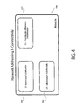
- FIG. 4 an overview of the Module of the present invention and sub-modules.
- FIG. 5 shows and exemplary overview of one embodiment of the Module of the present invention, the flow of steps and the flow of traffic.
- FIG. 6 shows an exemplary overview of network-attached devices operating using one embodiment of the present invention that includes a Remote Module.
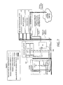
- FIG. 7 shows an exemplary overview of network attached devices operating using one embodiment of the present invention that includes a Direct Tunnel Module.
- a network based device needs to have certain mandatory addressing and connectivity information in order to communicate on any network.
- this device On a local area network (LAN) this device will send out a query asking for this network connectivity information.
- a server on the LAN will respond with this information which is local to this LAN. In all cases, this addressing and connectivity information assumes that the network based device is local and would behave as a local device.
- a hosts' connectivity query will traverse the compulsory tunnel to the headend LAN.
- a server on this LAN will respond with connectivity information towards the querying remote host/devices for its local headend network.
- the invention will automatically substitute the appropriate parameters so that the querying host's behavior will automatically use the tunnel for remote traffic and the split-tunnel for non-remote network traffic.
- the present invention does not require modification to the headend LAN server, the remote network, or the queried host/device.
- IP Internet Protocol used for network communications.
- IP Address refers to the unique address issued to hosts, devices applications and used for bi-direction or unidirectional communications between those hosts, devices, or applications.
- Device or devices refer to any host, device or application that uses or makes use of IP for communications.
- End-point device or devices refer to some application or device that provides the ability to begin or end a tunnel.
- Tunnel refers to the transparent bridged link between networks as provided by software.
- a bridged-link creates a single logical network although not physically co-located.
- Module refers to one particular embodiment of the invention, which refers to computer program logic for providing a specified functionality.
- One or more variations of the Module can be implemented in hardware, firmware, and/or software.
- the module is typically stored on a computer-readable storage medium such as the storage device, loaded into memory, and executed by a processor.
- Modules are referred to herein as S 1 , S 2 , S 3 , S 4 , S 5 , and the nomenclature is for illustrative purposes; other identification means could be assigned to the various Modules, such as M 1 , M 2 , and the like.
- An interface refers to a point of logical or logical/physical connection. Typically, the term interface is used in reference to an Ethernet or Ethernet-like port.
- a predetermined interface refers to either an automatic or manual configuration of the invention process to supply the desired information to the requesting host so that its traffic goes out the desired interface based on the traffic type offered.
- a packet refers to binary data capable of being routed through a computer network. To improve communication performance and reliability, each message sent between two network devices is often subdivided into packets by the underlying hardware and software.
- the present invention works within a typical network configuration and operationally performs the task of substituting a default router from an issuing DHCP server with an IP address of a local terminal. This allows the local terminal to forward outgoing traffic to a specific interface (Internet or tunnel) based on the destination of the address.
- a specific interface Internet or tunnel
- a device may take a variety of forms including, but not limited to, computing devices, mobile phones such as smart phones, tablet, desktop and laptop computers, media devices or any application or source operating on a processor such as mobile-phone application or various other applications as would be appreciated by those skilled in the art.
- a device attaches it will issue a DHCP request. If present, a DHCP server will respond with various network connectivity-information for the device.
- the basic information required for network connectivity include: an IP address and netmask; one or more DNS addresses; and a default gateway.
- a Tunnel When a Tunnel is initiated it will request a DHCP address from the local network from where it is attached. For example, based on FIG. 1 , Device 8 will obtain DHCP information from DHCP server 1 ; Device 9 will obtain DHCP information from DHCP server 7 . When a tunnel is created between the end-point devices 8 and 9 the attached Device 10 obtains its address from the native network DHCP server (Device 7 ) with the information for its network.
- the traffic flow from Device 10 would normally be presented to network 2 , and only to use the tunnel for traffic destined to network 6 .
- Device 8 would intercept the DHCP communication destined for DHCP server 7 , and substitute the proper network elements to facilitate the split-tunnel operation.
- Networks represent any type of communication network, including wire-based (i.e., fiber optic, cable, etc.), wireless (i.e., cellular, WiFi, Bluetooth, etc) or combinations thereof.
- Hosts represent any type of client or server computing device on the network. Each host may be configured to send and receive data.
- a host may be a dedicated server or router through which incoming or outgoing messages are routed on behalf of a client device, user, or application and use any suitable addressing protocol or layer.
- a server generally represents a name server that hosts a network service such as providing response to queries against a directory service. This may include addressing components such as IP addresses, amongst others as would be recognized by one skilled in the art.
- Hosts and server also represent any suitable computing device, which includes one or more processors and the ability to access a computer-readable media. Processors interact with computer-readable media to execute instructions that facilitate functionality of each router or server.
- Computer readable media may include any suitable computer-storage media including volatile and non-volatile memory, removable and non-removable media and any combination thereof.
- Computer readable media may include communication media that may embody computer readable instructions, data structures, program modules, or other data in a modulated data signal.
- FIG. 2 shows a typical network when a device seeks to access the Internet.
- the operating firmware of a device or application there will be several functions attempting to establish the device on the network.
- the industry has standardized on the DHCP protocol to provide device/application connectivity information.
- Once a device has the basic information of a unique IP address, netmask, and at least one DNS address it can completely access any other Internet address anywhere in the world.
- the networking and computing industry has standardized on DHCP as the preferred method for distributing connectivity information to devices which require and ask for this network connectivity information.
- a device When a device wishes to establish network connectivity its firmware will transmit to an available connection (either physical or logical) a DHCP discovery request. As the device does not yet have any network information it sends this out as a broadcast to any listening DHCP server.
- a DHCP server is a preconfigured network service existing on the local network. As it is setup for the local network, any devices requesting this connectivity information will receive the appropriate information to properly function.
- the applications are free to communicate with the Internet via local resources and services.
- Network-based services are used to support devices, applications, etc. These services are accessed via a physical or logical connection point, however these services may be found all on a single machine. The arrangement does not affect operation.
- FIG. 3 shows a network where a compulsory VPN is implemented ALL traffic is forced to the non-native network.
- any devices/applications will communicate with the network services—not locally—but through the VPN. Additionally, all network based application traffic will traverse over the VPN even for traffic not required or destined for the non-native network.
- FIG. 4 shows an overview of the Module 400 and sub-modules.
- Module 400 comprises various elements (sub-modules), designated S 1 , S 2 and S 3 .
- S 1 Intercept sub-module 402
- S 2 (Elements sub-module 404 ) comprises a substitution elements sub-module configured to obtain and establish the network items to be substituted.
- this sub-module may be configured to obtain these either statically (e.g., manually configured) or dynamically through pre-fetching from the DHCP server.
- remote configuration of the S 2 Elements sub-module, via a Remote Module is described further herein.
- S 3 substitution sub-module 406
- FIG. 5 shows an exemplary Module's configuration elements, and shows the traffic patterns for both the connectivity enquiry and the automatic traffic to both native or non-native resources (See Fig. Legend).
- the Module's configuration elements contain the substitution elements to be provided to the device. These elements can be pre-configured, automatically learned, or a combination of both, as described further below.
- the configuration of the module can be performed in different ways (for example: by setting properties of an embeddable component, by writing or modifying source code, by writing or modifying one or more configuration files, etc). Some or all of the configuration parameters may also be preset in the module, bundled with the module or hard-coded into the module.
- the module resides on a computing device which processes incoming and outgoing network messages as an application, firmware, or software.
- the module and sub-module assemblies are used at different phases of the communications cycle and operate when those phases are initiated or operated by the network messaging.
- predefined information can be queried in a database for retrieval as needed.
- This operation is carried out by way of a Remote Module 600 , shown as S 4 in FIG. 6 .
- the Remote Module 600 provides remote or centralized automatic query for acquisition of elements.
- Remote Module 600 places information for later retrieval, or query for information it may use for its own operation.
- Remote Module 600 uses the Domain Name System (DNS) system TXT data type to create a message based bi-directional communication system.
- DNS Domain Name System
- the DNS system allows for the retrieval of network information in a recursive manner attempting to resolve a queried host name.
- the DNS request (for any data type) can and will traverse through multiple random servers until it gets to the DNS server that is authoritative for that domain. Once that authoritative DNS server is found it attempt to honor the request with the stored information from its database.
- Remote Module codes various host names within a domain via a structure and places an associated TXT record also encoded with the desired information. For a remote fielded device to obtain information it is seeking it merely issues a standard DNS TXT record request for a coded-host name full-qualified-domain. The request, if available, will be delivered by the authoritative DNS server back to the querying device.
- the DNS system can be used to create a standard DNS NSUPDATE record to permit the remote addition or modification of data, in real time, from a remote device.
- DNS Internet Protocol
- the inherent nature of DNS, and its recursion, is a key benefit of the connectionless communications path.
- the module leverages this to provide a connectionless peer-to-peer or peer-to-many information management front-end.
- a device in city X configured with a Remote Module S 4 —with Remote Module in the “on” position.
- Remote Module 600 is a method for indirect connectionless bi-directional messaging over unknown network infrastructures. Where the method communicates with a database without the requirement for direct access to that database for either obtaining or placing information; and where the communications can contain an unlimited amount of discreet and selectable information elements; and where there is no direct acknowledgement of receipt of communications.
- the method codes discreet information elements as host names within a full-qualified-domain-name places an associated TXT record also encoded with the desired information; where remote device to obtain information it is seeking it merely issues a standard DNS TXT record request to any DNS server for a coded-host name full-qualified-domain; where the request will be delivered by the authoritative DNS server back to the querying device thorough one or more DNS servers.
- the method can be used to create a standard DNS NSUPDATE record to permit the remote addition or modification of data, in real time, from a remote device.
- VPN virtual private network
- the Direct Tunnel Module 700 permits one or more network devices to automatically discover capabilities for communications directly between associated end-points across one or more unknown networks even if both end points are behind a NAT or Firewall. It is important to note that Remote Module 700 does not require a relay or a special protocol for tunneling and can be used with standard or proprietary tunneling methods.
- client and server communications with the initiating device is the client and the receiving device is the server.
- NAT Network Address Translator
- each device when Direct Tunnel Module 700 is operating within two separate peer-devices, each device will initially and individually contact an offsite management server that can proxy the information between the two endpoints. They will exchange capabilities and information and begin a sequence of agreed upon outbound connections. The endpoint with the lower Ethernet MAC address will become the server with its peer the client. Each device will establish a sequence connection towards each other until one connection is discovered sufficient to establish direct endpoint-to-endpoint connectivity. At this point, the VPN or Tunnel can be initiated with the underlying networking transport already established.
- Direct Tunnel Module 700 facilitates the automatic creation of bi-directional direct peer-to-peer network connections through Internet Protocol based network address translators.
- Module 700 provides a method that permits one or more devices to automatically discover capabilities for communications directly between associated end-points across one or more unknown networks even if both end points are behind a NAT or Firewall, wherein the method does not require a server or relay function outside of each device network or a special protocol for the creation of a VPN, tunneling, or any other application.
- Module 700 is further configured so that each device will generate identity communications to a separate database; and each device will create multiple outbound communications sessions; and each device will report to the separate database the status and information of the initiated sessions; and each device will attempt connections on all of the sessions. A successful connection response will generate a handoff in each device to the requesting application.
Landscapes
- Engineering & Computer Science (AREA)
- Computer Networks & Wireless Communication (AREA)
- Signal Processing (AREA)
- Computer Security & Cryptography (AREA)
- Computer Hardware Design (AREA)
- Computing Systems (AREA)
- General Engineering & Computer Science (AREA)
- Data Exchanges In Wide-Area Networks (AREA)
Abstract
The invention presented herein permits split-routing to occur without any changes, modifications, or configuration of the requesting host, network stacks, network architectures and routing and forwarding behavior. The invention is carried out by way of a Module that intercepts the normal and standard DHCP communication between a requesting device and a DHCP server, and substitutes the elements within the server response with the Module's own predefined elements. These substitute elements leverage the behavior of standard protocols to gain desired device network behavior.
Description
This is a continuation application of U.S. patent application Ser. No. 14/185,395 filed on Feb. 20, 2014, which in turn claims priority to U.S. Provisional Patent Application No. 61/767,229 filed on Feb. 20, 2013, the contents both of which are hereby incorporated by reference in their entireties.
This application relates to the technical field of network communications; in particular, to Dynamic Host Configuration Protocol (DHCP) and network address modification.
In applications where there is a tunnel to a remote network it is often desirable to have traffic destined for the non-tunneled network to simply egress the local router towards the Internet. In typical VPN or Tunnel networks this is called a split-tunnel. Split tunneling is a computer networking concept which allows a VPN user to access a public network, e.g., the Internet, and a local LAN or WAN at the same time, using the same physical network connection. This connection service is usually facilitated through a program such as a VPN client software application.
In VPNs, there are basically two types of virtual tunnels that enable secure data transmission: full tunnels and split tunnels. In full tunnel mode, a remote user establishes an Internet connection from a client device, such as a PC, which then runs through the VPN. This naturally includes the user's private data traffic. As a result, every time the user scans the web, it is done through the VPN gateway.
For example, suppose a user utilizes a remote access VPN software client connecting to a corporate network using a hotel wireless network. The user with split tunneling enabled is able to connect to file servers, database servers, mail servers and other servers on the corporate network through the VPN connection. When the user connects to Internet resources (web sites, FTP sites, etc.,) the connection request goes directly out the gateway provided by the local network.
Usually, this network traffic behavior is accomplished via routing statements. But, in a transparent tunnel network architecture where there is no routing and a split-tunnel configuration would require manual configuration of all the network elements along the path.
Split tunneling has a variety of advantages. It only transmits data that actually requires the protection of a VPN, and it enables strict separation of corporate Internet traffic and private Internet use. Split tunneling manageability, however, depends on the quality of the implemented VPN components.
The invention presented herein permits split-routing to occur without any changes, modifications, or configuration of the requesting host, network stacks, network architectures and routing and forwarding behavior. The invention is carried out by way of a Module that intercepts the normal and standard DHCP communication between a requesting device and a DHCP server, and substitutes the elements within the server response with the Module's own elements. These substitute elements leverage the behavior of standard protocols to gain desired device network behavior.
Existing methods known in the art require setup of multiple LAN servers and/or routers (network elements) each with their own connectivity information or modification to the hosts to make use of split-tunnel. There is no known automatic method for dynamic IP addressing schemes. Also, the fixed methods also are a waste of limited network resources. There are no known methods which provide selectivity on a host basis to force some hosts to be use the tunnel exclusively in a compulsory mode and others to use the split tunnel while coexisting on the same LAN.
Described herein is a method of substituting network addressing elements with predefined information, thereby managing the flow of network traffic as it seeks egress to an alternate network, comprising: presenting an interface for intercepting a reply to a devices-DHCP request; substituting the reply with predefined information; and enabling a split-tunnel; substituting an IP address of an issuing DHCP server with an IP address of a local terminal; and forwarding resulting traffic on from the local terminal to a predetermined interface based on a destination of that address.
Also described is a computer software product for use with a computer, said computer software product comprising, and a module constructed and arranged to be embedded into a computer program, wherein the module is operable to provide substitution addressing elements to a DHCP-requesting device.
Another embodiment of the present invention is a computer-readable storage medium storing an executable computer program module for enabling substituting network addressing elements, the module comprising: an intercept sub-module configured to manage DHCP information between networks; an elements sub-module configured to obtain and establish the network items to be substituted; and a substitution sub-module configured to perform the operations of deconstructing, substituting, and rebuilding packets with predefined information, thereby allowing the module to manage the flow of network traffic as it seeks egress to an alternate network.
Yet another embodiment of the present invention is a method to permit split-routing to occur without any changes, modifications or configuration of a requesting host, network stack, network architecture, and routing and forwarding behavior, the method comprising: presenting a module to intercept the normal and standard DHCP communication between a requesting device and a DHCP server, wherein the module is configured for substituting the elements within the server response with the module's own elements, thereby directing traffic through an alternate route.
The summary is an overview of the concept in a simplified form and not intended to identify essential features of the claimed subject matter, nor is it necessarily intended to be used as an aid in determining the scope of the claimed subject matter.
The detailed description is described with reference to the accompanying drawings. In the drawings, the left-most digit of a reference number identifies the figure to which the reference number first appears.
A network based device needs to have certain mandatory addressing and connectivity information in order to communicate on any network. On a local area network (LAN) this device will send out a query asking for this network connectivity information. A server on the LAN will respond with this information which is local to this LAN. In all cases, this addressing and connectivity information assumes that the network based device is local and would behave as a local device.
In situations where a compulsory (all traffic if forced) tunnel VPN or Tunnel is installed all of the remote network traffic from remote devices is sent to the headquarters network. When a network based device needs it connectivity information in this environment it will receive its addressing and connectivity query response—not from the local server—but the remote server at the headquarters. As such all network traffic from the remote site will traverse the tunnel even traffic not destined for use or processing by that network (compulsory tunneling). In many cases it is desired to have only the network traffic for the remote network traverse the tunnel whilst all non-remote network traffic (local traffic) automatically traverse via its local network connection. This is often called a split-tunnel where there are two different paths for flows to traverse. The present invention is designed to automatically enforce the split-tunnel behavior on networks with multiple DHCP servers.
In order to have specified devices (indicated in a list of specified devices in the process) or all devices on a network, at any time, be able to use this split-tunnel, the connectivity certain parameters must be modified prior to delivery to that host so that the desired information received by the device ensures its proper behavior of either compulsory or split-tunnel behavior.
When a VPN or Tunnel is installed a hosts' connectivity query will traverse the compulsory tunnel to the headend LAN. A server on this LAN will respond with connectivity information towards the querying remote host/devices for its local headend network. The invention will automatically substitute the appropriate parameters so that the querying host's behavior will automatically use the tunnel for remote traffic and the split-tunnel for non-remote network traffic.
The present invention does not require modification to the headend LAN server, the remote network, or the queried host/device.
Existing methods known in the art require setup of multiple LAN servers and/or routers (network elements) each with their own connectivity information or modification to the hosts to make use of split-tunnel. There is no known automatic method for having a single automatic address scheme across multiple networks and/or multiple gateways. Also, the fixed methods also are a waste of limited network resources. There not known methods which provide selectivity on a host basis to force some hosts to be use the tunnel exclusively in a compulsory mode and others to use the split tunnel while coexisting on the same LAN (layer-2 environment.)
The following terms are used to describe different aspects of the invention and the environment in which the invention operates. These terms are used for explanation purposes only and are not intended to limit the scope for any aspect of the invention.
IP refers to Internet Protocol used for network communications.
IP Address refers to the unique address issued to hosts, devices applications and used for bi-direction or unidirectional communications between those hosts, devices, or applications.
Device or devices refer to any host, device or application that uses or makes use of IP for communications. End-point device or devices refer to some application or device that provides the ability to begin or end a tunnel.
Tunnel refers to the transparent bridged link between networks as provided by software.
A bridged-link creates a single logical network although not physically co-located.
Module refers to one particular embodiment of the invention, which refers to computer program logic for providing a specified functionality. One or more variations of the Module can be implemented in hardware, firmware, and/or software. The module is typically stored on a computer-readable storage medium such as the storage device, loaded into memory, and executed by a processor. Modules are referred to herein as S1, S2, S3, S4, S5, and the nomenclature is for illustrative purposes; other identification means could be assigned to the various Modules, such as M1, M2, and the like.
An interface refers to a point of logical or logical/physical connection. Typically, the term interface is used in reference to an Ethernet or Ethernet-like port. This reference assumes that the interface structures present an IP-based behavior posture.
A predetermined interface refers to either an automatic or manual configuration of the invention process to supply the desired information to the requesting host so that its traffic goes out the desired interface based on the traffic type offered.
A packet refers to binary data capable of being routed through a computer network. To improve communication performance and reliability, each message sent between two network devices is often subdivided into packets by the underlying hardware and software.
Illustrative Network Environment
The present invention works within a typical network configuration and operationally performs the task of substituting a default router from an issuing DHCP server with an IP address of a local terminal. This allows the local terminal to forward outgoing traffic to a specific interface (Internet or tunnel) based on the destination of the address.
Consider the following typical network drawing shown in FIG. 1 , where each network is independent with its own DHCP server on its network. As used in this description, a device may take a variety of forms including, but not limited to, computing devices, mobile phones such as smart phones, tablet, desktop and laptop computers, media devices or any application or source operating on a processor such as mobile-phone application or various other applications as would be appreciated by those skilled in the art.
On each network, when a device attaches it will issue a DHCP request. If present, a DHCP server will respond with various network connectivity-information for the device. The basic information required for network connectivity include: an IP address and netmask; one or more DNS addresses; and a default gateway.
When a Tunnel is initiated it will request a DHCP address from the local network from where it is attached. For example, based on FIG. 1 , Device 8 will obtain DHCP information from DHCP server 1; Device 9 will obtain DHCP information from DHCP server 7. When a tunnel is created between the end- point devices 8 and 9 the attached Device 10 obtains its address from the native network DHCP server (Device 7) with the information for its network.
Therefore, it may be desirable for some Device 10 users traffic not destined for the native network—via the tunnel—to simply egress the local router (Device 3) normally. But the DHCP information offered over the tunnel would force all Device 10's traffic to traverse the tunnel and egress via the native network's router (Device 6).
Therefore, in many instances, the traffic flow from Device 10 would normally be presented to network 2, and only to use the tunnel for traffic destined to network 6.
Employing the invention as described herein, Device 8 would intercept the DHCP communication destined for DHCP server 7, and substitute the proper network elements to facilitate the split-tunnel operation.
Networks represent any type of communication network, including wire-based (i.e., fiber optic, cable, etc.), wireless (i.e., cellular, WiFi, Bluetooth, etc) or combinations thereof.
Hosts represent any type of client or server computing device on the network. Each host may be configured to send and receive data. A host may be a dedicated server or router through which incoming or outgoing messages are routed on behalf of a client device, user, or application and use any suitable addressing protocol or layer.
A server generally represents a name server that hosts a network service such as providing response to queries against a directory service. This may include addressing components such as IP addresses, amongst others as would be recognized by one skilled in the art.
Hosts and server also represent any suitable computing device, which includes one or more processors and the ability to access a computer-readable media. Processors interact with computer-readable media to execute instructions that facilitate functionality of each router or server.
Processors may be distributed in more than one computer system and over a network. Computer readable media may include any suitable computer-storage media including volatile and non-volatile memory, removable and non-removable media and any combination thereof. In another embodiment, computer readable media may include communication media that may embody computer readable instructions, data structures, program modules, or other data in a modulated data signal.
Standard/Typical Behavior of Network Attached Devices on a Local Network
The networking and computing industry has standardized on DHCP as the preferred method for distributing connectivity information to devices which require and ask for this network connectivity information.
When a device wishes to establish network connectivity its firmware will transmit to an available connection (either physical or logical) a DHCP discovery request. As the device does not yet have any network information it sends this out as a broadcast to any listening DHCP server. A DHCP server is a preconfigured network service existing on the local network. As it is setup for the local network, any devices requesting this connectivity information will receive the appropriate information to properly function.
After the device is connected, or has its connectivity information, the applications are free to communicate with the Internet via local resources and services.
Network-based services are used to support devices, applications, etc. These services are accessed via a physical or logical connection point, however these services may be found all on a single machine. The arrangement does not affect operation.
Standard/Typical Behavior of Network Attached Devices when a Compulsory VPN is Activated
Network Behavior Employing the Exemplary Module
When using the Exemplary Module, traffic ONLY destined for the non-native network will traverse the tunnel. This is called a split-tunnel. The key advantage of the Exemplary Module is that the Module can operate automatically without pre-configuration.
Depending on the implementation and form of distribution, the configuration of the module can be performed in different ways (for example: by setting properties of an embeddable component, by writing or modifying source code, by writing or modifying one or more configuration files, etc). Some or all of the configuration parameters may also be preset in the module, bundled with the module or hard-coded into the module.
In one embodiment, the module resides on a computing device which processes incoming and outgoing network messages as an application, firmware, or software. The module and sub-module assemblies are used at different phases of the communications cycle and operate when those phases are initiated or operated by the network messaging.
Remote Query of Pre-Defined Information Via Remote Module
In another embodiment, predefined information can be queried in a database for retrieval as needed. This operation is carried out by way of a Remote Module 600, shown as S4 in FIG. 6 . The Remote Module 600 provides remote or centralized automatic query for acquisition of elements. Remote Module 600 places information for later retrieval, or query for information it may use for its own operation. In one embodiment, Remote Module 600 uses the Domain Name System (DNS) system TXT data type to create a message based bi-directional communication system.
The DNS system allows for the retrieval of network information in a recursive manner attempting to resolve a queried host name. The DNS request (for any data type) can and will traverse through multiple random servers until it gets to the DNS server that is authoritative for that domain. Once that authoritative DNS server is found it attempt to honor the request with the stored information from its database. Remote Module codes various host names within a domain via a structure and places an associated TXT record also encoded with the desired information. For a remote fielded device to obtain information it is seeking it merely issues a standard DNS TXT record request for a coded-host name full-qualified-domain. The request, if available, will be delivered by the authoritative DNS server back to the querying device. Additionally, the DNS system can be used to create a standard DNS NSUPDATE record to permit the remote addition or modification of data, in real time, from a remote device. The inherent nature of DNS, and its recursion, is a key benefit of the connectionless communications path. The module leverages this to provide a connectionless peer-to-peer or peer-to-many information management front-end.
A device in city X configured with a Remote Module S4—with Remote Module in the “on” position.
-
- The device will obtain it's public IP address on its main interface (not module specific)
- The device will then create a DNS NSUPDATE record to a user specified domain
- this is example.com—to push the learned knowledge of what it has just learned
- it's pubic IP.
- The update will send the devices Ethernet MAC address plus an pre-pend as the HOST part (pip.xx-xx-xx-xx-xx-xx.example.net) with the INFO text record data as “<publiclP.y.y.y.y>”
- Any other device anywhere looking to contact this specific unit can use the same DNS system and simply ask for the INFO record of pip.xx-xx-xx-xx-xx-xx.example.net for which will be returned <publiclP.y.y.y.y>.
- An unlimited of host pre-pends and INFO text record formats can used to allow for direct addressing of such things (but not limited to) as DHCP hosts, DHCP gateways, System Uptime Status, Firmware updates, or logging.
Thus, also envisioned in the present invention—by way of Remote Module 600—is a method for indirect connectionless bi-directional messaging over unknown network infrastructures. Where the method communicates with a database without the requirement for direct access to that database for either obtaining or placing information; and where the communications can contain an unlimited amount of discreet and selectable information elements; and where there is no direct acknowledgement of receipt of communications.
In one embodiment, the method codes discreet information elements as host names within a full-qualified-domain-name places an associated TXT record also encoded with the desired information; where remote device to obtain information it is seeking it merely issues a standard DNS TXT record request to any DNS server for a coded-host name full-qualified-domain; where the request will be delivered by the authoritative DNS server back to the querying device thorough one or more DNS servers. In another embodiment, the method can be used to create a standard DNS NSUPDATE record to permit the remote addition or modification of data, in real time, from a remote device.
Alternate Embodiment for Establishing Tunnel to Non-Native Network
When a host is installed on the network there are situations where it will desire to communicate directly with another peer across that network. The network infrastructure may not permit this direct communication through a variety of known and/or unknown limitations. Often these limitations are out of the control of the each host's network providers. This situation is particularly difficult when creating a virtual private network (VPN) tunnel between sites as NAT or Firewall gateways are free to make outbound connections but block any ad-hoc in-bound connections.
Thus, also envisioned in the present invention is a Direct Tunnel Module 700, shown as S5 in FIG. 7 . The Direct Tunnel Module 700 permits one or more network devices to automatically discover capabilities for communications directly between associated end-points across one or more unknown networks even if both end points are behind a NAT or Firewall. It is important to note that Remote Module 700 does not require a relay or a special protocol for tunneling and can be used with standard or proprietary tunneling methods. When two VPN network device wish to establish a direct peer-to-peer connection for the purpose of tunnel connectivity it is necessary that one endpoint receives the initial setup request from end-point towards its peer-endpoint. Often this is referred as client and server communications with the initiating device is the client and the receiving device is the server.
Most networks operate with a Network Address Translator (NAT) and create a private IP address network for its hosts. For an endpoint initiating an outbound network connection, meaning the message traverses the private network toward the public IP through the NAT, communications are unimpeded. When a public-to-private connection is to be initially established a NAT router will block this connection as it does not recognize the connection or which host on the private network it should send it to.
In one embodiment, when Direct Tunnel Module 700 is operating within two separate peer-devices, each device will initially and individually contact an offsite management server that can proxy the information between the two endpoints. They will exchange capabilities and information and begin a sequence of agreed upon outbound connections. The endpoint with the lower Ethernet MAC address will become the server with its peer the client. Each device will establish a sequence connection towards each other until one connection is discovered sufficient to establish direct endpoint-to-endpoint connectivity. At this point, the VPN or Tunnel can be initiated with the underlying networking transport already established.
In another embodiment, Direct Tunnel Module 700 facilitates the automatic creation of bi-directional direct peer-to-peer network connections through Internet Protocol based network address translators. In yet another embodiment, Module 700 provides a method that permits one or more devices to automatically discover capabilities for communications directly between associated end-points across one or more unknown networks even if both end points are behind a NAT or Firewall, wherein the method does not require a server or relay function outside of each device network or a special protocol for the creation of a VPN, tunneling, or any other application. Module 700 is further configured so that each device will generate identity communications to a separate database; and each device will create multiple outbound communications sessions; and each device will report to the separate database the status and information of the initiated sessions; and each device will attempt connections on all of the sessions. A successful connection response will generate a handoff in each device to the requesting application.
Reference herein to “example”, “embodiments” or similar formulations means that a particular feature, structure, operation or characteristic described in connection with the example, is included in at least one implementation in this description. Thus, the appearance of such phrases or formulations herein is not necessarily all referring to the same example. Further, various particular features, structures, operations or characteristics may be combined in any suitable manner in one or more examples, and or embodiments.
Claims (2)
1. A method for initiating a direct tunnel between previously unconnected endpoints residing on an otherwise obstructed network path, comprising:
sending, via a native endpoint configured with a direct connect module, a message comprising identifying information and status information of the native endpoint to a management database;
sending, via a nonnative endpoint configured with a direct connect module, a message comprising identifying information and status information of the nonnative endpoint to a management database;
sending, via the management database, a message comprising a unique ID packet of the native endpoint to the nonnative endpoint;
sending, via the management database, a message comprising a unique ID packet of the nonnative endpoint to the native endpoint;
upon receiving a nonnative endpoint unique ID, initiating a sequence of outbound communication sessions from a sending native endpoint to the nonnative endpoint;
upon receiving a native endpoint unique ID, initiating a sequence of outbound communication sessions from a sending nonnative endpoint to the native endpoint;
discovering by the direct connect module a connection between the previously unconnected endpoints upon receiving by the direct connect module the outbound communication from the sending endpoint at a receiving endpoint, wherein the receiving endpoint is one of a nonnative endpoint receiving the outbound communication from the sending native endpoint or a native endpoint receiving the outbound communication from the sending nonnative endpoint;
synchronizing by the direct connect module status information between the connected endpoints;
identifying the sending endpoint address as a server endpoint and the remaining endpoint as a client endpoint; and
disengaging by the direct connect module communication from the management database by the server endpoint and client endpoint, thereby permitting direct endpoint-to-endpoint connectivity and establishing a direct tunnel between the previously unconnected endpoints.
2. A non-transitory computer-readable medium storing computer-readable instructions that, when executed by a processor of a computing device, instruct the processor to perform a method for generating a direct tunnel between endpoints residing on an otherwise obstructed network path, comprising:
sending, via a native endpoint configured with a direct connect module, a message comprising identifying information and status information of the native endpoint to a management database by the direct connect module;
sending, via a nonnative endpoint configured with a direct connect module, a message comprising identifying information and status information of the nonnative endpoint to a management database;
sending, via the management database, a message comprising a unique ID packet of the native endpoint to the nonnative endpoint;
sending, via the management database, a message comprising a unique ID packet of the nonnative endpoint to the native endpoint;
upon receiving a nonnative endpoint unique ID, initiating a sequence of outbound communication sessions from a sending native endpoint to the nonnative endpoint;
upon receiving a native endpoint unique ID, initiating a sequence of outbound communication sessions from a sending nonnative endpoint to the native endpoint;
discovering by the direct connect module a connection between the previously unconnected endpoints upon receiving the outbound communication from the sending endpoint at a receiving endpoint, wherein the receiving endpoint is one of the nonnative endpoint receiving the outbound communication from the sending native endpoint or the native endpoint receiving the outbound communication from the sending nonnative endpoint;
synchronizing by the direct connect module status information between the connected endpoints;
identifying the sending endpoint address as a server endpoint and the remaining endpoint as a client endpoint; and
disengaging communication from the management database by the server endpoint and client endpoint, thereby permitting direct endpoint-to-endpoint connectivity and establishing a direct tunnel between the previously unconnected endpoints.
Priority Applications (4)
| Application Number | Priority Date | Filing Date | Title |
|---|---|---|---|
| US15/206,830 US9876757B2 (en) | 2013-02-20 | 2016-07-11 | Systems and methods for dynamic network address modification |
| US15/875,978 US10154005B2 (en) | 2013-02-20 | 2018-01-19 | System and methods for direct connections between previously unconnected network devices across one or more unknown networks |
| US15/875,921 US10659430B2 (en) | 2013-02-20 | 2018-01-19 | Systems and methods for dynamic network address modification related applications |
| US16/170,260 US10469444B2 (en) | 2013-02-20 | 2018-10-25 | System and method for direct connections between previously unconnected network devices across one or more unknown networks |
Applications Claiming Priority (3)
| Application Number | Priority Date | Filing Date | Title |
|---|---|---|---|
| US201361767229P | 2013-02-20 | 2013-02-20 | |
| US14/185,395 US9391881B2 (en) | 2013-02-20 | 2014-02-20 | System and methods for dynamic network address modification |
| US15/206,830 US9876757B2 (en) | 2013-02-20 | 2016-07-11 | Systems and methods for dynamic network address modification |
Related Parent Applications (1)
| Application Number | Title | Priority Date | Filing Date |
|---|---|---|---|
| US14/185,395 Continuation US9391881B2 (en) | 2013-02-20 | 2014-02-20 | System and methods for dynamic network address modification |
Related Child Applications (2)
| Application Number | Title | Priority Date | Filing Date |
|---|---|---|---|
| US15/875,978 Continuation US10154005B2 (en) | 2013-02-20 | 2018-01-19 | System and methods for direct connections between previously unconnected network devices across one or more unknown networks |
| US15/875,921 Continuation US10659430B2 (en) | 2013-02-20 | 2018-01-19 | Systems and methods for dynamic network address modification related applications |
Publications (2)
| Publication Number | Publication Date |
|---|---|
| US20160323242A1 US20160323242A1 (en) | 2016-11-03 |
| US9876757B2 true US9876757B2 (en) | 2018-01-23 |
Family
ID=51729914
Family Applications (5)
| Application Number | Title | Priority Date | Filing Date |
|---|---|---|---|
| US14/185,395 Active 2034-05-25 US9391881B2 (en) | 2013-02-20 | 2014-02-20 | System and methods for dynamic network address modification |
| US15/206,830 Active US9876757B2 (en) | 2013-02-20 | 2016-07-11 | Systems and methods for dynamic network address modification |
| US15/875,978 Active US10154005B2 (en) | 2013-02-20 | 2018-01-19 | System and methods for direct connections between previously unconnected network devices across one or more unknown networks |
| US15/875,921 Active US10659430B2 (en) | 2013-02-20 | 2018-01-19 | Systems and methods for dynamic network address modification related applications |
| US16/170,260 Active US10469444B2 (en) | 2013-02-20 | 2018-10-25 | System and method for direct connections between previously unconnected network devices across one or more unknown networks |
Family Applications Before (1)
| Application Number | Title | Priority Date | Filing Date |
|---|---|---|---|
| US14/185,395 Active 2034-05-25 US9391881B2 (en) | 2013-02-20 | 2014-02-20 | System and methods for dynamic network address modification |
Family Applications After (3)
| Application Number | Title | Priority Date | Filing Date |
|---|---|---|---|
| US15/875,978 Active US10154005B2 (en) | 2013-02-20 | 2018-01-19 | System and methods for direct connections between previously unconnected network devices across one or more unknown networks |
| US15/875,921 Active US10659430B2 (en) | 2013-02-20 | 2018-01-19 | Systems and methods for dynamic network address modification related applications |
| US16/170,260 Active US10469444B2 (en) | 2013-02-20 | 2018-10-25 | System and method for direct connections between previously unconnected network devices across one or more unknown networks |
Country Status (1)
| Country | Link |
|---|---|
| US (5) | US9391881B2 (en) |
Cited By (2)
| Publication number | Priority date | Publication date | Assignee | Title |
|---|---|---|---|---|
| US11108652B2 (en) | 2018-12-18 | 2021-08-31 | At&T Intellectual Property I, L.P. | Server assisted network discovery (SAND) |
| US11171915B2 (en) | 2018-06-29 | 2021-11-09 | Electronics And Telecommunications Research Institute | Server apparatus, client apparatus and method for communication based on network address mutation |
Families Citing this family (11)
| Publication number | Priority date | Publication date | Assignee | Title |
|---|---|---|---|---|
| US10135792B2 (en) * | 2015-08-25 | 2018-11-20 | Anchorfree Inc. | Secure communications with internet-enabled devices |
| US10929048B2 (en) * | 2018-10-01 | 2021-02-23 | EMC IP Holding Company LLC | Dynamic multiple proxy deployment |
| US11032175B2 (en) * | 2018-12-31 | 2021-06-08 | Hughes Network Systems | Packet loss isolation test |
| WO2020256705A1 (en) * | 2019-06-18 | 2020-12-24 | Visa International Service Association | Cross-border quick response (qr) payment flow for encrypted primary account number (pan) payment flow |
| US10992638B1 (en) * | 2020-06-08 | 2021-04-27 | Amazon Technologies, Inc. | Network address translation based on logical channel implementation in a shared wireless network |
| US11349932B2 (en) * | 2020-06-30 | 2022-05-31 | Cisco Technology, Inc. | Policy-based connection provisioning using domain name system (DNS) requests |
| US11223599B1 (en) * | 2020-08-17 | 2022-01-11 | Netflix, Inc. | Techniques for templated domain management |
| US11095612B1 (en) | 2020-10-30 | 2021-08-17 | Palo Alto Networks, Inc. | Flow metadata exchanges between network and security functions for a security service |
| US11785048B2 (en) * | 2020-10-30 | 2023-10-10 | Palo Alto Networks, Inc. | Consistent monitoring and analytics for security insights for network and security functions for a security service |
| CN113286011B (en) * | 2021-04-27 | 2023-08-22 | 锐捷网络股份有限公司 | IP address allocation method and device based on VXLAN |
| CN114124902B (en) * | 2021-11-12 | 2023-07-04 | 迈普通信技术股份有限公司 | Multi-activation detection method and system |
Citations (16)
| Publication number | Priority date | Publication date | Assignee | Title |
|---|---|---|---|---|
| US6305020B1 (en) * | 1995-11-01 | 2001-10-16 | Ictv, Inc. | System manager and hypertext control interface for interactive cable television system |
| US20040264465A1 (en) * | 2002-11-27 | 2004-12-30 | Dunk Craig A. | Data transfer from a host server via a tunnel server to a wireless device, and associating a temporary ipv6 address with a temporary ipv4 address for communicating in an ipv4 wireless network with the device |
| US20050163078A1 (en) * | 2004-01-22 | 2005-07-28 | Toshiba America Research, Inc. | Mobility architecture using pre-authentication, pre-configuration and/or virtual soft-handoff |
| US20060245373A1 (en) * | 2005-04-27 | 2006-11-02 | Symbol Technologies, Inc | Method, system and apparatus for creating a mesh network of wireless switches to support layer 3 roaming in wireless local area networks (WLANs) |
| US20060245393A1 (en) * | 2005-04-27 | 2006-11-02 | Symbol Technologies, Inc. | Method, system and apparatus for layer 3 roaming in wireless local area networks (WLANs) |
| US20060245404A1 (en) * | 2005-04-27 | 2006-11-02 | Symbol Technologies, Inc. | Method, system and apparatus for creating an active client list to support layer 3 roaming in wireless local area networks (WLANs) |
| US20060268781A1 (en) * | 2005-05-02 | 2006-11-30 | Telefonaktiebolaget Lm Ericsson (Publ) | System and method for call handoff from packet data wireless network to circuit switched wireless network |
| US20080267096A1 (en) * | 2004-09-30 | 2008-10-30 | Adin Research, Inc. | Tunnel Device, Relay Device, Terminal Device, Call Control System, Ip Telephone System, Conference Device, and Their Control Method and Program |
| US20100008260A1 (en) * | 2006-12-04 | 2010-01-14 | Sun Cheul Kim | Method for configuring control tunnel and direct tunnel in ipv4 network-based ipv6 service providing system |
| US20100246506A1 (en) * | 2009-03-26 | 2010-09-30 | Qualcomm Incorporated | Apparatus and methods of whitespace communication |
| US20110013559A1 (en) * | 2009-07-16 | 2011-01-20 | Motorola, Inc. | Wireless communication via a tunnel through a serving access network |
| US20110082941A1 (en) * | 2009-10-06 | 2011-04-07 | Electronics And Telecommunications Research Institute | Method of providing direct communication in internet protocol network |
| US20110270996A1 (en) * | 2008-12-08 | 2011-11-03 | Electronics And Telecommunications Research Institute | Method for configuring closed user network using ip tunneling mechanism and closed user network system |
| US20120150993A1 (en) * | 2010-10-29 | 2012-06-14 | Akamai Technologies, Inc. | Assisted delivery of content adapted for a requesting client |
| US20130304796A1 (en) * | 2010-09-29 | 2013-11-14 | Citrix Systems, Inc. | Systems and methods for providing quality of service via a flow controlled tunnel |
| US20160182458A1 (en) * | 2014-12-17 | 2016-06-23 | Cisco Technology, Inc. | End-to-end security for virtual private service chains |
Family Cites Families (47)
| Publication number | Priority date | Publication date | Assignee | Title |
|---|---|---|---|---|
| US20020172206A1 (en) * | 2001-05-18 | 2002-11-21 | Vaman Dhadesugoor R. | Method for providing domain name services for heterogeneous transport networks |
| US7356596B2 (en) * | 2001-12-07 | 2008-04-08 | Architecture Technology Corp. | Protecting networks from access link flooding attacks |
| US7509644B2 (en) * | 2003-03-04 | 2009-03-24 | Secure 64 Software Corp. | Operating system capable of supporting a customized execution environment |
| US8473635B1 (en) * | 2003-05-19 | 2013-06-25 | Akamai Technologies, Inc. | Provisioning tool for a distributed computer network |
| US8661158B2 (en) * | 2003-12-10 | 2014-02-25 | Aventail Llc | Smart tunneling to resources in a network |
| US20050262357A1 (en) * | 2004-03-11 | 2005-11-24 | Aep Networks | Network access using reverse proxy |
| US20050273849A1 (en) * | 2004-03-11 | 2005-12-08 | Aep Networks | Network access using secure tunnel |
| US20050251856A1 (en) * | 2004-03-11 | 2005-11-10 | Aep Networks | Network access using multiple authentication realms |
| WO2006014504A2 (en) * | 2004-07-07 | 2006-02-09 | Sciencelogic, Llc | Self configuring network management system |
| US8700729B2 (en) * | 2005-01-21 | 2014-04-15 | Robin Dua | Method and apparatus for managing credentials through a wireless network |
| JP4635682B2 (en) * | 2005-03-29 | 2011-02-23 | ブラザー工業株式会社 | Information processing apparatus, information processing method, and information processing program |
| US8816828B2 (en) * | 2005-06-09 | 2014-08-26 | Whirlpool Corporation | Recipe wand and recipe book for use with a networked appliance |
| US7873993B2 (en) * | 2005-11-09 | 2011-01-18 | Cisco Technology, Inc. | Propagating black hole shunts to remote routers with split tunnel and IPSec direct encapsulation |
| US20070186281A1 (en) * | 2006-01-06 | 2007-08-09 | Mcalister Donald K | Securing network traffic using distributed key generation and dissemination over secure tunnels |
| US7774837B2 (en) * | 2006-06-14 | 2010-08-10 | Cipheroptics, Inc. | Securing network traffic by distributing policies in a hierarchy over secure tunnels |
| CN101155084B (en) * | 2006-09-28 | 2011-04-13 | 华为技术有限公司 | Method and system for acquiring network topological information |
| US8046820B2 (en) * | 2006-09-29 | 2011-10-25 | Certes Networks, Inc. | Transporting keys between security protocols |
| US7764691B2 (en) * | 2007-03-15 | 2010-07-27 | Microsoft Corporation | Allowing IPv4 clients to communicate using teredo addresses when both clients are behind a NAT |
| US7715386B2 (en) * | 2007-03-15 | 2010-05-11 | Microsoft Corporation | Reducing network traffic to teredo server |
| US20080225867A1 (en) * | 2007-03-15 | 2008-09-18 | Microsoft Corporation | Faster NAT detection for Teredo client |
| DE102007053839B4 (en) * | 2007-11-12 | 2009-09-24 | Fraunhofer-Gesellschaft zur Förderung der angewandten Forschung e.V. | Use of a coated, transparent substrate to influence the human psyche |
| US9183368B2 (en) * | 2008-01-24 | 2015-11-10 | Go Daddy Operating Company, LLC | Validating control of domain zone |
| US8395989B2 (en) * | 2008-04-23 | 2013-03-12 | Verizon Patent And Licensing Inc. | Method and system for network backbone analysis |
| US8677018B2 (en) * | 2008-08-25 | 2014-03-18 | Google Inc. | Parallel, side-effect based DNS pre-caching |
| US8285875B2 (en) * | 2009-01-28 | 2012-10-09 | Juniper Networks, Inc. | Synchronizing resource bindings within computer network |
| US8423631B1 (en) * | 2009-02-13 | 2013-04-16 | Aerohive Networks, Inc. | Intelligent sorting for N-way secure split tunnel |
| US9083587B2 (en) * | 2009-08-21 | 2015-07-14 | Cisco Technology, Inc. | Port chunk allocation in network address translation |
| US8386590B2 (en) * | 2009-10-01 | 2013-02-26 | At&T Intellectual Property I, Lp | Method and apparatus for managing rehoming of user endpoint devices in a communication network |
| US8533780B2 (en) * | 2009-12-22 | 2013-09-10 | Cisco Technology, Inc. | Dynamic content-based routing |
| KR101480929B1 (en) * | 2010-02-12 | 2015-01-12 | 인터디지탈 테크날러지 코포레이션 | Data split between multiple sites |
| US9319921B2 (en) * | 2011-06-14 | 2016-04-19 | Nec Corporation | Load distribution in an EPC network of a mobile communication system |
| US8891552B2 (en) * | 2011-11-08 | 2014-11-18 | Cisco Technology, Inc. | Managed access to mobile endpoints |
| US8837474B2 (en) * | 2011-12-19 | 2014-09-16 | Qualcomm Incorporated | Apparatus and methods for efficient network address translation and application level gateway processing |
| US8908698B2 (en) * | 2012-01-13 | 2014-12-09 | Cisco Technology, Inc. | System and method for managing site-to-site VPNs of a cloud managed network |
| US20130182651A1 (en) * | 2012-01-13 | 2013-07-18 | Amol Dhananjay Kelkar | Virtual Private Network Client Internet Protocol Conflict Detection |
| KR101896420B1 (en) * | 2012-01-16 | 2018-09-11 | 노키아 솔루션스 앤드 네트웍스 오와이 | Vendor specific base station auto-configuration framework |
| US9008093B2 (en) * | 2012-03-12 | 2015-04-14 | Comcast Cable Communications, Llc | Stateless protocol translation |
| US9124633B1 (en) * | 2012-03-29 | 2015-09-01 | Infoblox Inc. | IP address and domain name automation of virtual infrastructure |
| US8892766B1 (en) * | 2012-06-28 | 2014-11-18 | Trend Micro Incorporated | Application-based network traffic redirection for cloud security service |
| US8832433B2 (en) * | 2012-08-17 | 2014-09-09 | Cellco Partnership | Methods and systems for registering a packet-based address for a mobile device using a fully-qualified domain name (FQDN) for the device in a mobile communication network |
| US9419985B1 (en) * | 2012-09-25 | 2016-08-16 | Morta Security Inc | Interrogating malware |
| US9451530B2 (en) * | 2012-11-02 | 2016-09-20 | Telefonaktiebolaget L M Ericsson (Publ) | Methods for base-station-to-base-station connection management |
| JP2014135592A (en) * | 2013-01-09 | 2014-07-24 | Sony Corp | Information processing device, information processing method, and information processing system |
| US9497083B1 (en) * | 2013-06-10 | 2016-11-15 | Palo Alto Networks, Inc. | Discovering network nodes |
| US9124625B1 (en) * | 2013-06-11 | 2015-09-01 | Morta Security Inc | Interdicting undesired service |
| US10057167B2 (en) * | 2014-04-09 | 2018-08-21 | Tallac Networks, Inc. | Identifying end-stations on private networks |
| US10206092B1 (en) * | 2017-09-29 | 2019-02-12 | Hewlett Packard Enterprise Development Lp | Automatic discovery |
-
2014
- 2014-02-20 US US14/185,395 patent/US9391881B2/en active Active
-
2016
- 2016-07-11 US US15/206,830 patent/US9876757B2/en active Active
-
2018
- 2018-01-19 US US15/875,978 patent/US10154005B2/en active Active
- 2018-01-19 US US15/875,921 patent/US10659430B2/en active Active
- 2018-10-25 US US16/170,260 patent/US10469444B2/en active Active
Patent Citations (17)
| Publication number | Priority date | Publication date | Assignee | Title |
|---|---|---|---|---|
| US6305020B1 (en) * | 1995-11-01 | 2001-10-16 | Ictv, Inc. | System manager and hypertext control interface for interactive cable television system |
| US20100172302A1 (en) * | 2002-11-27 | 2010-07-08 | Research In Motion Limited | IPv4-to-IPv6 Address Transitioning Methods And Apparatus For Systems That Push Information To Wireless Communication Devices |
| US20040264465A1 (en) * | 2002-11-27 | 2004-12-30 | Dunk Craig A. | Data transfer from a host server via a tunnel server to a wireless device, and associating a temporary ipv6 address with a temporary ipv4 address for communicating in an ipv4 wireless network with the device |
| US20050163078A1 (en) * | 2004-01-22 | 2005-07-28 | Toshiba America Research, Inc. | Mobility architecture using pre-authentication, pre-configuration and/or virtual soft-handoff |
| US20080267096A1 (en) * | 2004-09-30 | 2008-10-30 | Adin Research, Inc. | Tunnel Device, Relay Device, Terminal Device, Call Control System, Ip Telephone System, Conference Device, and Their Control Method and Program |
| US20060245373A1 (en) * | 2005-04-27 | 2006-11-02 | Symbol Technologies, Inc | Method, system and apparatus for creating a mesh network of wireless switches to support layer 3 roaming in wireless local area networks (WLANs) |
| US20060245393A1 (en) * | 2005-04-27 | 2006-11-02 | Symbol Technologies, Inc. | Method, system and apparatus for layer 3 roaming in wireless local area networks (WLANs) |
| US20060245404A1 (en) * | 2005-04-27 | 2006-11-02 | Symbol Technologies, Inc. | Method, system and apparatus for creating an active client list to support layer 3 roaming in wireless local area networks (WLANs) |
| US20060268781A1 (en) * | 2005-05-02 | 2006-11-30 | Telefonaktiebolaget Lm Ericsson (Publ) | System and method for call handoff from packet data wireless network to circuit switched wireless network |
| US20100008260A1 (en) * | 2006-12-04 | 2010-01-14 | Sun Cheul Kim | Method for configuring control tunnel and direct tunnel in ipv4 network-based ipv6 service providing system |
| US20110270996A1 (en) * | 2008-12-08 | 2011-11-03 | Electronics And Telecommunications Research Institute | Method for configuring closed user network using ip tunneling mechanism and closed user network system |
| US20100246506A1 (en) * | 2009-03-26 | 2010-09-30 | Qualcomm Incorporated | Apparatus and methods of whitespace communication |
| US20110013559A1 (en) * | 2009-07-16 | 2011-01-20 | Motorola, Inc. | Wireless communication via a tunnel through a serving access network |
| US20110082941A1 (en) * | 2009-10-06 | 2011-04-07 | Electronics And Telecommunications Research Institute | Method of providing direct communication in internet protocol network |
| US20130304796A1 (en) * | 2010-09-29 | 2013-11-14 | Citrix Systems, Inc. | Systems and methods for providing quality of service via a flow controlled tunnel |
| US20120150993A1 (en) * | 2010-10-29 | 2012-06-14 | Akamai Technologies, Inc. | Assisted delivery of content adapted for a requesting client |
| US20160182458A1 (en) * | 2014-12-17 | 2016-06-23 | Cisco Technology, Inc. | End-to-end security for virtual private service chains |
Cited By (2)
| Publication number | Priority date | Publication date | Assignee | Title |
|---|---|---|---|---|
| US11171915B2 (en) | 2018-06-29 | 2021-11-09 | Electronics And Telecommunications Research Institute | Server apparatus, client apparatus and method for communication based on network address mutation |
| US11108652B2 (en) | 2018-12-18 | 2021-08-31 | At&T Intellectual Property I, L.P. | Server assisted network discovery (SAND) |
Also Published As
| Publication number | Publication date |
|---|---|
| US20180183755A1 (en) | 2018-06-28 |
| US20190036734A1 (en) | 2019-01-31 |
| US20160323242A1 (en) | 2016-11-03 |
| US10469444B2 (en) | 2019-11-05 |
| US10154005B2 (en) | 2018-12-11 |
| US20140317312A1 (en) | 2014-10-23 |
| US20190068547A1 (en) | 2019-02-28 |
| US9391881B2 (en) | 2016-07-12 |
| US10659430B2 (en) | 2020-05-19 |
Similar Documents
| Publication | Publication Date | Title |
|---|---|---|
| US10659430B2 (en) | Systems and methods for dynamic network address modification related applications | |
| US9485147B2 (en) | Method and device thereof for automatically finding and configuring virtual network | |
| EP2579544B1 (en) | Methods and apparatus for a scalable network with efficient link utilization | |
| JP5711754B2 (en) | Smart client routing | |
| KR100901790B1 (en) | CONTROL TUNNEL AND DIRECT TUNNEL CONFIGURATION METHOD IN IPv6 SERVICE PROVIDE SYSTEM BASED IPv4 NETWORK | |
| TWI524188B (en) | Method, computer program product and system for providing virtual networks using multi-tenant relays | |
| WO2016119747A1 (en) | System and method for communicating in an ssl vpn | |
| US10637831B2 (en) | Method and apparatus for transmitting network traffic via a proxy device | |
| US20080005290A1 (en) | Terminal reachability | |
| WO2019080592A1 (en) | Method and device for sending messages | |
| US8873569B2 (en) | User centric virtual network and method of establishing the same | |
| JP2019519146A (en) | Routing establishment, packet transmission | |
| WO2009018658A1 (en) | Device, system and method for automatic ipv4 provisioning in a local area network connected to an ipv6 network | |
| EP4236270A2 (en) | Software defined access fabric without subnet restriction to a virtual network | |
| Jeong | IPv6 Host Configuration of DNS Server Information Approaches | |
| US10505892B2 (en) | Method for transmitting at least one IP data packet, related system and computer program product | |
| KR20180007898A (en) | Method for separating groups within tenent in virtual private cloud network | |
| EP3228048B1 (en) | Method and apparatus for routing data to cellular network | |
| JP3808471B2 (en) | Network and router apparatus and address notification method used therefor | |
| JP2001057572A (en) | Access routing method and access providing system | |
| Horley et al. | IPv6 Addressing | |
| Jeong | RFC 4339: IPv6 Host Configuration of DNS Server Information Approaches |
Legal Events
| Date | Code | Title | Description |
|---|---|---|---|
| STCF | Information on status: patent grant |
Free format text: PATENTED CASE |
|
| CC | Certificate of correction | ||
| MAFP | Maintenance fee payment |
Free format text: PAYMENT OF MAINTENANCE FEE, 4TH YR, SMALL ENTITY (ORIGINAL EVENT CODE: M2551); ENTITY STATUS OF PATENT OWNER: SMALL ENTITY Year of fee payment: 4 |