US9867608B1 - Suturing instrument with circular needle motion - Google Patents
Suturing instrument with circular needle motion Download PDFInfo
- Publication number
- US9867608B1 US9867608B1 US14/740,924 US201514740924A US9867608B1 US 9867608 B1 US9867608 B1 US 9867608B1 US 201514740924 A US201514740924 A US 201514740924A US 9867608 B1 US9867608 B1 US 9867608B1
- Authority
- US
- United States
- Prior art keywords
- needle
- link
- drive
- input
- assembly
- Prior art date
- Legal status (The legal status is an assumption and is not a legal conclusion. Google has not performed a legal analysis and makes no representation as to the accuracy of the status listed.)
- Active, expires
Links
Images


Classifications
-
- A—HUMAN NECESSITIES
- A61—MEDICAL OR VETERINARY SCIENCE; HYGIENE
- A61B—DIAGNOSIS; SURGERY; IDENTIFICATION
- A61B17/00—Surgical instruments, devices or methods, e.g. tourniquets
- A61B17/04—Surgical instruments, devices or methods, e.g. tourniquets for suturing wounds; Holders or packages for needles or suture materials
- A61B17/0469—Suturing instruments for use in minimally invasive surgery, e.g. endoscopic surgery
-
- A—HUMAN NECESSITIES
- A61—MEDICAL OR VETERINARY SCIENCE; HYGIENE
- A61B—DIAGNOSIS; SURGERY; IDENTIFICATION
- A61B17/00—Surgical instruments, devices or methods, e.g. tourniquets
- A61B17/04—Surgical instruments, devices or methods, e.g. tourniquets for suturing wounds; Holders or packages for needles or suture materials
- A61B17/0482—Needle or suture guides
-
- A—HUMAN NECESSITIES
- A61—MEDICAL OR VETERINARY SCIENCE; HYGIENE
- A61B—DIAGNOSIS; SURGERY; IDENTIFICATION
- A61B17/00—Surgical instruments, devices or methods, e.g. tourniquets
- A61B17/04—Surgical instruments, devices or methods, e.g. tourniquets for suturing wounds; Holders or packages for needles or suture materials
- A61B17/06—Needles ; Sutures; Needle-suture combinations; Holders or packages for needles or suture materials
- A61B17/06114—Packages or dispensers for needles or sutures
-
- A—HUMAN NECESSITIES
- A61—MEDICAL OR VETERINARY SCIENCE; HYGIENE
- A61B—DIAGNOSIS; SURGERY; IDENTIFICATION
- A61B17/00—Surgical instruments, devices or methods, e.g. tourniquets
- A61B2017/0046—Surgical instruments, devices or methods, e.g. tourniquets with a releasable handle; with handle and operating part separable
- A61B2017/00473—Distal part, e.g. tip or head
-
- A—HUMAN NECESSITIES
- A61—MEDICAL OR VETERINARY SCIENCE; HYGIENE
- A61B—DIAGNOSIS; SURGERY; IDENTIFICATION
- A61B17/00—Surgical instruments, devices or methods, e.g. tourniquets
- A61B17/04—Surgical instruments, devices or methods, e.g. tourniquets for suturing wounds; Holders or packages for needles or suture materials
- A61B2017/0498—Surgical instruments, devices or methods, e.g. tourniquets for suturing wounds; Holders or packages for needles or suture materials for advancing a suture filament along a helical path through tissue
-
- A—HUMAN NECESSITIES
- A61—MEDICAL OR VETERINARY SCIENCE; HYGIENE
- A61B—DIAGNOSIS; SURGERY; IDENTIFICATION
- A61B17/00—Surgical instruments, devices or methods, e.g. tourniquets
- A61B17/04—Surgical instruments, devices or methods, e.g. tourniquets for suturing wounds; Holders or packages for needles or suture materials
- A61B17/06—Needles ; Sutures; Needle-suture combinations; Holders or packages for needles or suture materials
- A61B17/06066—Needles, e.g. needle tip configurations
- A61B2017/0608—J-shaped
Definitions
- Sutures may be used in a wide variety of surgical procedures. Manual suturing may be accomplished by the surgeon using a fine pair of graspers to grab and hold a suture needle, pierce the tissue with the needle, let go of the needle, and re-grasp the needle to pull the needle and accompanying suture thread through the tissues to be sutured. Such needles may be curved with the suture attached to the trailing end of the needle.
- Some surgical instruments automate at least part of the suturing procedure. Examples of automated suturing instruments are described in U.S. Pat. No. 8,702,732, entitled “Laparoscopic Suturing Instrument with Dual-Action Needle Graspers,” issued Apr. 22, 2014, the disclosure of which is incorporated by reference herein; U.S. Pub. No. 2011/0313433, entitled “Laparoscopic Suture Device with Asynchronous In-Line Needle Movement,” published Dec. 22, 2011, now U.S. Pat. No. 9,168,037, issued Oct. 27, 2015, the disclosure of which is incorporated by reference herein; U.S. Pub. No. 2014/0171970, entitled “Circular Needle Applier with Articulating and Rotating Shaft,” published Jun.
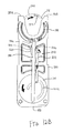
- FIG. 1 depicts a side view of an exemplary surgical suturing instrument
- FIG. 2A depicts top perspective exploded view of a cartridge receiving assembly of the instrument of FIG. 1 ;
- FIG. 2B depicts bottom perspective exploded view of the cartridge receiving assembly of FIG. 2A ;
- FIG. 3A depicts a top perspective view of an exemplary cartridge configured for receipt in the cartridge receiving assembly of FIG. 2A ;
- FIG. 3B depicts a bottom perspective view of the cartridge of FIG. 3A ;
- FIG. 4 depicts an exploded view of the cartridge of FIG. 3A ;
- FIG. 5A depicts a perspective view of a drive assembly of the cartridge of FIG. 3A , with the drive assembly at one end of its stroke;
- FIG. 5B depicts a perspective view of the drive assembly of FIG. 5A , with the drive assembly at mid-stroke;
- FIG. 5C depicts a perspective view of the drive assembly of FIG. 5A , with the drive assembly at the other end of its stroke;
- FIG. 6 depicts a partial plan view of a needle driver of the cartridge of FIG. 3A engaging a needle of the cartridge of FIG. 3A ;
- FIG. 7 depicts a perspective view of another exemplary cartridge configured for receipt in the cartridge receiving assembly of FIG. 2A ;
- FIG. 8 depicts another perspective view of the cartridge of FIG. 7 ;
- FIG. 9 depicts an exploded view of the cartridge of FIG. 7 ;
- FIG. 10 depicts a perspective view of a guide member of the cartridge of FIG. 7 ;
- FIG. 11 depicts a perspective view of a cam wheel of the cartridge of FIG. 7 ;
- FIG. 12A depicts a top plan view of the cartridge of FIG. 7 , with external components removed to reveal internal components, with the cartridge at a first stage of actuation;
- FIG. 12B depicts a top plan view of the cartridge of FIG. 7 , with external components removed to reveal internal components, with the cartridge at a second stage of actuation;
- FIG. 12C depicts a top plan view of the cartridge of FIG. 7 , with external components removed to reveal internal components, with the cartridge at a third stage of actuation;
- FIG. 12D depicts a top plan view of the cartridge of FIG. 7 , with external components removed to reveal internal components, with the cartridge at a fourth stage of actuation;
- FIG. 13 depicts a perspective view of another exemplary cartridge configured for receipt in the cartridge receiving assembly of FIG. 2A ;
- FIG. 14 depicts another perspective view of the cartridge of FIG. 13 ;
- FIG. 15 depicts an exploded view of the cartridge of FIG. 13 ;
- FIG. 16 depicts a perspective view of a translating cam member of the cartridge of FIG. 13 ;
- FIG. 17 depicts another perspective view of the translating cam member of FIG. 16 ;
- FIG. 18 depicts a perspective view of a guide member of the cartridge of FIG. 13 ;
- FIG. 19 depicts a perspective view of a guide rod of the cartridge of FIG. 13 ;
- FIG. 20 depicts a perspective view of a cam plate of the cartridge of FIG. 13 ;
- FIG. 21A depicts a top plan view of the cartridge of FIG. 13 , with external components removed to reveal internal components, with the cartridge at a first stage of actuation;
- FIG. 21B depicts a top plan view of the cartridge of FIG. 13 , with external components removed to reveal internal components, with the cartridge at a second stage of actuation;
- FIG. 21C depicts a top plan view of the cartridge of FIG. 13 , with external components removed to reveal internal components, with the cartridge at a third stage of actuation;
- FIG. 21D depicts a top plan view of the cartridge of FIG. 13 , with external components removed to reveal internal components, with the cartridge at a fourth stage of actuation.
- FIG. 1 illustrates an example of a surgical suturing instrument ( 2 ).
- Instrument ( 2 ) comprises a handle assembly ( 10 ), an elongate shaft ( 20 ), and a cartridge receiving assembly ( 50 ), which is operable to receive a needle applier cartridge ( 30 ).
- Shaft ( 20 ) has a proximal end ( 21 ), a distal end ( 22 ), and a longitudinal axis extending therebetween.
- Handle assembly ( 10 ) is connected to the proximal end ( 21 ) of the shaft ( 20 ).
- handle assembly ( 10 ) is a manual pistol grip handle.
- Handle assembly ( 10 ) could also take the form of a robotic interface, such as a DAVINCI puck, or a housing comprising gears or pulleys, servomechanisms, and the like.
- Needle applier cartridge ( 30 ) is connected to the distal end ( 22 ) of shaft ( 20 ) via cartridge receiving assembly ( 50 ). Needle applier cartridge ( 30 ) is operable to rotate an arced needle in a circular path enabling a surgeon to selectively apply sutures.
- needle applier cartridge ( 30 ) is integral with shaft ( 20 ) and handle assembly ( 10 ) as a unitary disposable instrument intended for a single surgical procedure. Needle applier cartridge ( 30 ) may also be integral with shaft ( 20 ) and handle assembly ( 10 ) as a reusable instrument.
- needle applier cartridge ( 30 ) may be provided in a disposable cartridge body ( 90 ) and shaft ( 20 ) includes cartridge receiving assembly ( 50 ) to releasably hold cartridge body ( 90 ).
- shaft ( 20 ) and handle assembly ( 10 ) may also be disposable or reusable. Versions with reusable components are intended to be cleaned, sterilized, and reused for a multiple surgical procedures, and may include a flush port ( 18 ) to facilitate cleaning.
- the preferable life cycle of a reusable instrument is at least 50 operations, more preferably at least 150 operations, and most preferably at least 200 operations.
- Reusable components may be built using materials that can withstand autoclave sterilization temperatures of at least 135 degrees Celsius, although low temperature materials can also be used with low temperature sterilization techniques known in the art.
- a first input ( 12 ), shown here as a trigger that pivots between opened and closed positions, may be used to selectively actuate needle applier cartridge ( 30 ).
- the trigger may be spring biased to return the trigger to its open position.
- a second input ( 14 ), shown here as a rotary knob, may be used to selectively articulate shaft ( 20 ).
- a third input ( 16 ), shown here as a rotary knob, may be used to selectively rotate needle applier cartridge ( 30 ) about shaft ( 20 ).
- the number, type, configuration, and operation of inputs ( 12 , 14 , 16 ) may vary.
- FIGS. 2A-2B illustrate exploded views of cartridge receiving assembly ( 50 ) of the present example.
- Distal end ( 22 ) of shaft ( 20 ) comprises an articulation joint ( 23 ) and a rotational bearing ( 24 ).
- Articulation joint ( 23 ) includes a knuckle ( 23 A) that receives pins ( 23 B, 23 C), which are connected to bearing supports ( 24 B, 24 C).
- pins ( 23 B, 2 C) define the pivoting axis for articulation joint ( 23 ), enabling cartridge receiving assembly ( 50 ) to articulate left and right relative the shaft ( 20 ), away from the longitudinal axis defined by shaft ( 20 ).
- Rods ( 27 A, 27 B) are operably connected to articulation joint ( 23 ).
- rods ( 27 A, 27 B) extend through shaft ( 20 ), through knuckle ( 23 A), and connect to pins ( 29 A, 29 B) on bearing support ( 24 C).
- Rods ( 27 A, 27 B) are operatively connected to second input ( 14 ) to opposingly push and pull rods ( 27 A, 27 B).
- second input ( 14 ) is operable to drive rods ( 27 A, 27 B) at the same time in opposite longitudinal directions, such that rod ( 27 A) will translate distally while rod ( 27 B) translates proximally; and such that rod ( 27 B) will translate distally while rod ( 27 A) translates proximally. Because pins ( 29 A, B) are laterally spaced from the pivoting axis, the simultaneous push and pull action will in turn articulate cartridge receiving assembly ( 50 ) about joint ( 23 ) relative to shaft ( 20 ).
- Rotational bearing ( 24 ) is positioned distal to articulation joint ( 23 ).
- Bearing ( 24 ) includes a circumferential flange ( 24 A) that is captured between the bearing supports ( 24 B, 24 C) such that the flange ( 24 A) can rotate relative the bearing supports ( 24 B, 24 C) and enabling unbounded rotation of cartridge receiving assembly ( 50 ) relative shaft ( 20 ) about the longitudinal axis defined by shaft ( 20 ).
- a drive rod ( 28 ) extends through shaft ( 20 ).
- drive rod ( 28 ) comprises a proximal rigid portion ( 28 A) and a distal bendable portion ( 28 B) that are fixedly connected to one another. Bendable portion ( 28 B) extends through articulation joint ( 23 ) and through bearing ( 24 ); distal end ( 28 C) is fixedly connected to a mount ( 49 ) on a rack ( 45 ).
- Rack ( 45 ) reciprocates longitudinally in lower jaw ( 51 ) with followers ( 45 A, 45 B, 45 C, 45 D) constrained in tracks ( 55 A, 55 B, 55 C, 55 D), respectively.
- Tracks ( 55 A, 55 B, 55 C, 55 D) open through lower jaw ( 51 ), providing fluid passages to the internal components within the lower jaw ( 51 ), thus facilitating easier cleaning.
- a pinion ( 47 ) is mounted to lower jaw ( 51 ) by the pin ( 46 ) in the rack ( 45 ) such that longitudinal reciprocation of the rack ( 45 ) is converted into rotational reciprocation of pinion ( 47 ).
- a key ( 48 ) communicates the reciprocating rotation to a rotary input ( 94 ) in cartridge body ( 90 ), which in turn actuates needle applier cartridge ( 30 ).
- Drive rod ( 28 ) is operatively connected to first input ( 12 ) and to third input ( 16 ). Actuation of first input ( 12 ) will impart axial push and pull loads on drive rod ( 28 ) to longitudinally reciprocate rack ( 45 ) and thereby actuate needle applier cartridge ( 30 ). Actuation of third input ( 16 ) will impart a rotational load on drive rod ( 28 ) thus rotating cartridge receiving assembly ( 50 ) about bearing ( 24 ) relative to shaft ( 20 ). Accordingly, a single drive rod ( 28 ) operates to both actuate needle applier cartridge ( 30 ) as well as control distal rotation of needle applier cartridge ( 30 ) about the longitudinal axis of shaft ( 20 ). By consolidating dual functions with a single drive rod ( 28 ), the number of components is reduced, and more space is provided in the shaft ( 20 ), which may make the device less expensive to manufacture and easier to clean.
- Cartridge receiving assembly ( 50 ) is dimensioned and adapted to receive and hold cartridge body ( 90 ).
- cartridge receiving assembly ( 50 ) of this example has upper and lower jaws ( 56 , 51 ) that are operable to transition between an open configuration and a closed configuration. In the closed configuration, jaws ( 56 , 51 ) are operable to receive and retain cartridge body ( 90 ). In the open configuration, jaws ( 56 , 51 ) are operable to release cartridge body ( 90 ).
- lower jaw ( 51 ) is stationary and upper jaw ( 56 ) pivots. Alternatively, the arrangement could be reversed, or in some versions both jaws ( 56 , 51 ) could pivot.
- Lower jaw ( 51 ) has two laterally offset longitudinal rails ( 52 ) that are dimensioned and adapted to receive cartridge body ( 90 ). Rails ( 52 ) help longitudinally align cartridge body ( 90 ) in cartridge receiving assembly ( 50 ) and laterally retain cartridge body ( 90 ) in jaws ( 51 , 56 ). Upper jaw ( 56 ) pivots relative lower jaw ( 51 ) about a pin ( 53 ) that is received in holes ( 57 ). A tooth ( 59 ) is resiliently oriented downwardly from upper jaw ( 56 ) toward lower jaw ( 51 ) with a ramped distal face and a stepped proximal face.
- Tooth ( 59 ) is dimensioned and adapted to latch with cartridge body ( 90 ) and longitudinally retain cartridge body ( 90 ) in jaws ( 51 , 56 ). Tooth ( 59 ) deflects by virtue of a resilient cantilevered arm extending proximally from the distal end of upper jaw ( 56 ). In this example, tooth ( 59 ) and the cantilevered arm are monolithic with upper jaw ( 56 ), thus reducing the number of components and moving pieces, which may make the device less expensive to manufacture and easier to clean.
- a button ( 60 ) is operable to open and close jaws ( 51 , 56 ). While button ( 60 ) could be placed on or near the handle assembly ( 10 ) in some versions, in this example button ( 60 ) is positioned adjacent cartridge receiving assembly ( 50 ), which eliminates a linkage in shaft ( 20 ) thus creating space in shaft ( 20 ) and making the device less expensive and easier to clean.
- the action of button ( 60 ) may vary, but in this example button ( 60 ) pivots relative to lower jaw ( 51 ) about a pin ( 63 ) that is received hole ( 61 ).
- a follower ( 62 ) is received by cam slots ( 54 , 58 ).
- Pivoting button ( 60 ) proximally will open jaws ( 51 , 56 ), while pivoting button ( 60 ) distally will close jaws ( 51 , 56 ).
- a spring ( 64 ) engages and biases button ( 60 ) distally. By pulling button ( 60 ) proximally, follower ( 62 ) will drive cam slot ( 58 ) to open upper jaw ( 56 ). When button ( 60 ) is released, spring ( 64 ) will resiliently drive button ( 60 ) distally to close upper jaw ( 56 ).
- FIGS. 3A-3B illustrate cartridge body ( 90 ) of the present example in greater detail.
- a lower face ( 91 ) of cartridge body ( 90 ) is adapted to engage lower jaw ( 51 ); and an upper face ( 96 ) to engage upper jaw ( 56 ).
- Poke-yoke features on cartridge body ( 90 ) prevent improper insertion of cartridge body ( 90 ) into cartridge receiving assembly ( 50 ), but also contribute to the aesthetic appearance of cartridge body ( 90 ).
- lower face ( 91 ) has a pair of longitudinal notched shoulders ( 92 ) that are dimensioned to interface and mate with rails ( 52 ).
- notched shoulders ( 92 ) are shaped as a stepped rabbet, but a variety of other aesthetic shapes could also be employed such as chamfers and radii.
- upper face ( 96 ) is asymmetrical relative lower face ( 91 ) and lacks shoulder notches, so upper face ( 96 ) would interfere with rails ( 52 ) if cartridge body ( 90 ) were inserted upside-down in cartridge receiving assembly ( 50 ).
- the geometry of a proximal face ( 98 ) of cartridge body ( 90 ) is vertically asymmetrical and thus prevents cartridge body ( 90 ) from being inserted upside-down between jaws ( 51 , 56 ).
- proximal face ( 98 ) comprises a curved surface that gently transitions to upper face ( 96 ), which matches similar geometry in cartridge receiving assembly ( 50 ); while the transition to lower face ( 91 ) has a tighter radius.
- a variety of other asymmetrical aesthetic geometries could also be employed that could contribute to the visual appearance and/or poke-yoke aspects of cartridge body ( 90 ).
- Arms ( 93 A, 93 B) define a generally U-shaped distal end on cartridge body ( 90 ).
- a slot ( 95 ) and rotary input ( 94 ) are aligned and dimensioned to receive the key ( 48 ) while cartridge body ( 90 ) is being slid into cartridge receiving assembly ( 50 ).
- a step ( 99 ) aligns with and receives tooth ( 59 ) to latch cartridge body ( 90 ) in cartridge receiving assembly ( 50 ).
- Key ( 48 ) also aligns with rotary input ( 94 ), thereby providing a torsional interface that rotationally couples pinion ( 47 ) and rotary input ( 94 ).
- the needle ( 70 ) exits arm ( 93 A) and enters arm ( 93 B).
- cartridge body ( 90 ) further comprises a lower body ( 81 ), an upper body ( 82 ), a needle ( 70 ), and a needle cover ( 83 ).
- Needle driver ( 86 ), rotary input ( 94 ), and a link ( 85 ) are captured between lower body ( 81 ) and upper body ( 82 ).
- Bodies ( 81 , 82 ) may be attached to one another using a variety of known techniques, including welds, pins, adhesives, and the like to form cartridge body ( 90 ).
- Needle ( 70 ) has a leading end ( 71 ) and a length of suture ( 73 ) extending from the trailing end ( 72 ).
- Needle ( 70 ) orbits in a circular path defined by a needle track ( 84 ) and between arms ( 93 A, 93 B). Needle ( 70 ) includes notches ( 74 ) that are configured to facilitate engagement between needle driver ( 86 ) and needle ( 70 ). Needle ( 70 ) is captured in needle track ( 84 ) by needle cover ( 83 ). A cage ( 87 ) slides over bodies ( 81 , 82 ) and needle cover ( 83 ) to attach needle cover ( 83 ) against lower body ( 81 ).
- FIGS. 5A-5C illustrate an example of a drive stroke of the transmission in cartridge body ( 90 ) for driving needle ( 70 ) in a circular, orbital path.
- Needle driver ( 86 ) rides in a carrier track ( 88 ) and extends into needle track ( 84 ) to engage and drive needle ( 70 ).
- a link ( 85 ) connects rotary input ( 94 ) to needle driver ( 86 ).
- FIG. 5A shows needle driver ( 86 ) positioned at one end of its stroke in carrier track ( 88 ). As shown in FIG.
- Needle driver ( 86 ) is disengaged from needle ( 70 ) during the return stroke until needle driver ( 86 ) reaches the end of the return stroke. Needle driver ( 86 ) will re-engage needle ( 86 ) upon completing the return stroke. Thus, a sequence of drive and return strokes will rotate the needle ( 70 ) in a circular path.
- FIG. 6 illustrates a detailed view of needle driver ( 86 ) engaging needle ( 70 ).
- Needle driver ( 86 ) comprises a carrier ( 86 A) and a driver ( 86 B).
- Carrier ( 86 A) is dimensioned to slideably fit in carrier track ( 88 ).
- Driver ( 86 B) is attached to carrier ( 75 ) and is operative to engage needle ( 70 ) at an oblique angle.
- Leftward movement of needle driver ( 86 ) will cause driver ( 86 B) to engage proximal notch ( 74 ) of needle ( 70 ) during the drive stroke.
- needle ( 70 ) will slide in needle track ( 84 ) in unison with needle driver ( 86 ). Due to the oblique angle, rightward movement of needle driver ( 86 ) will disengage driver ( 86 B) from proximal notch ( 74 ) of needle ( 70 ) and slide over the stationary needle ( 70 ) during the return stroke.
- needle driver ( 86 ) when first input ( 12 ) is depressed, closing the trigger, needle driver ( 86 ) will be actuated through its drive stroke where it orbits along an angular range of motion at least about 180 degrees counterclockwise to a driven position as shown in FIG. 5C .
- driver ( 86 B) engages proximal notch ( 74 ) and will in unison rotate needle ( 70 ) about 180 degrees along an orbital path to its extended position. Needle ( 70 ) will span across arms ( 93 A, 93 B) between exit port ( 95 ) and entrance port ( 97 ). Tissue interposed between arms ( 93 A, 93 B) will be pierced by leading end ( 71 ) of needle ( 70 ).
- needle driver ( 86 ) When first input ( 12 ) is released and the spring return opens the trigger, needle driver ( 86 ) reciprocates through its return stroke where it orbits along an angular range of motion about 180 degrees clockwise back to the return position shown in FIG. 5A . During the return stroke, driver ( 86 B) slides over the needle ( 70 ). Driver ( 86 B) is then adjacent the distal notch ( 74 ). When first input ( 12 ) is depressed again closing the trigger, needle driver ( 86 ) will again be actuated through its drive stroke where it orbits along an angular range of motion about 180 degrees counterclockwise to the driven position as shown in FIG. 5C .
- driver ( 86 B) engages distal notch ( 74 ) and will in unison drive needle ( 70 ) orbitally along an angular range of motion about 180 degrees back to its retracted position. Suture ( 73 ) will follow needle ( 70 ) and be threaded through the pierced tissue.
- needle driver ( 86 ) again reciprocates through its return stroke where it orbits along an angular range of motion about 180 degrees clockwise back to its returned position as shown in FIG. 5A .
- driver ( 86 B) slides over needle ( 70 ).
- needle ( 70 ) is driven in a complete circular path spanning an angular range of 360° in response to first input ( 12 ) being actuated twice. The sequence may be repeated as needed by the surgeon to achieve the desired suturing task.
- instrument ( 2 ) in conjunction with a needle applier cartridge similar to needle applier cartridge ( 30 ) described above, but with various alternative features related to driving a needle driver like needle driver ( 86 ).
- a needle applier cartridge similar to needle applier cartridge ( 30 ) described above, but with various alternative features related to driving a needle driver like needle driver ( 86 ).
- needle applier cartridge it may be desirable to include features configured to maintain movement of a link, similar to link ( 85 ) described above, in a relatively circular path.
- needle applier cartridges it may be desirable to provide a linear drive input as an alternative to rotary input ( 94 ) described above. Needle applier cartridges having such features may be desirable to generally improve the usability of instrument ( 2 ).
- such features may contribute to driving the needle driver more fluidly than needle driver ( 86 ), thus making first input ( 12 ) more easily actuated by a surgeon.
- certain features described below may require fewer components making the instrument less expensive and easier to clean.
- FIGS. 7-9 shown an alternative needle applier cartridge ( 130 ) that may be used with instrument ( 2 ) described above.
- needle applier cartridge ( 130 ) of the present example is substantially the same as needle applier cartridge ( 30 ) described above, unless otherwise noted herein, such that needle applier cartridge ( 130 ) may be readily used in place of needle applier cartridge ( 30 ).
- needle applier cartridge ( 130 ) comprises a cartridge body ( 190 ).
- Cartridge body ( 190 ) comprises a lower face ( 191 ) that is adapted to engage lower jaw ( 51 ); and an upper face ( 196 ) that is adapted to engage upper jaw ( 56 ).
- cartridge body ( 190 ) Like with cartridge body ( 90 ) described above, poke-yoke features on cartridge body ( 190 ) prevent improper insertion of cartridge body ( 190 ) into cartridge receiving assembly ( 50 ).
- lower face ( 191 ) has a pair of longitudinal notched shoulders ( 192 ) that are dimensioned to interface and mate with rails ( 52 ).
- upper face ( 196 ) is asymmetrical relative lower face ( 191 ) and lacks shoulder notches, so upper face ( 196 ) would interfere with rails ( 52 ) if cartridge body ( 190 ) were inserted upside-down in cartridge receiving assembly ( 50 ).
- proximal face ( 198 ) of cartridge body ( 190 ) is vertically asymmetrical and thus prevents cartridge body ( 190 ) from being inserted upside-down between jaws ( 51 , 56 ).
- proximal face ( 198 ) comprises a curved surface that gently transitions to upper face ( 196 ), which matches similar geometry in cartridge receiving assembly ( 50 ); while the transition to lower face ( 191 ) has a tighter radius.
- a variety of other asymmetrical aesthetic geometries could also be employed that could contribute to the visual appearance and/or poke-yoke aspects of cartridge body ( 190 ).
- a slot ( 195 ) and rotary input ( 194 ) are aligned and dimensioned to receive the key ( 48 ) while cartridge body ( 190 ) is being slid into cartridge receiving assembly ( 50 ).
- a step ( 199 ) aligns with and receives tooth ( 59 ) to latch cartridge body ( 190 ) in cartridge receiving assembly ( 50 ).
- Key ( 48 ) also aligns with rotary input ( 194 ), thereby providing a torsional interface that rotationally couples pinion ( 47 ) and rotary input ( 194 ).
- a needle ( 170 ) exits arm ( 193 A) and enters arm ( 193 B).
- cartridge body ( 190 ) further comprises a lower body ( 181 ), an upper body ( 182 ), a needle ( 170 ), and a needle cover ( 183 ).
- a needle driver ( 186 ), rotary input ( 194 ), a link ( 185 ), and a guide assembly ( 210 ) are captured between lower body ( 181 ) and upper body ( 182 ).
- Needle ( 170 ) has a leading end ( 171 ) and a length of suture (not shown) extending from a trailing end ( 172 ). Needle ( 170 ) orbits in a circular path defined by a needle track ( 184 ) and between arms ( 193 A, 193 B).
- Needle ( 170 ) includes notches ( 174 ) that are configured to facilitate engagement between needle driver ( 186 ) and needle ( 170 ). Needle ( 170 ) is captured in needle track ( 184 ) by needle cover ( 183 ). A cage ( 187 ) slides over bodies ( 181 , 182 ) and needle cover ( 183 ) to attach needle cover ( 183 ) against lower body ( 181 ).
- needle applier cartridge ( 130 ) of the present example further comprises guide assembly ( 210 ).
- guide assembly ( 210 ) is generally configured to aid the distal end of link ( 185 ) in movement along a generally semi-circular path.
- Guide assembly ( 210 ) comprises a guide link ( 212 ) and a guide member ( 220 ).
- Guide link ( 212 ) comprises an elongate rigid beam and is generally configured to transfer rotary movement of rotary input ( 194 ) to guide member ( 220 ) as will be described in greater detail below.
- Guide link ( 212 ) comprises a proximal pin ( 214 ) and a distal pin ( 215 ).
- Proximal pin ( 214 ) is configured to engage a cam path ( 202 ) that is formed in at least a portion of rotary input ( 194 ).
- distal pin ( 215 ) is received in a first opening ( 222 ) of guide member ( 220 ).
- guide link ( 212 ) is configured such that proximal pin ( 214 ) is directed along the path defined by cam path ( 202 ) of rotary input ( 194 ) to move guide member ( 220 ) along a predetermined path via distal pin ( 215 ).
- Guide member ( 220 ) is best seen in FIG. 10 .
- guide member ( 220 ) comprises first opening ( 222 ), a second opening ( 224 ), and a pair of guide protrusions ( 226 ).
- first opening is configured to receive distal pin ( 215 ) of guide link ( 212 ).
- Second opening ( 224 ) is configured to receive a post ( 225 ) extending upwardly from lower body ( 181 ) to permit guide member ( 220 ) to pivot about post ( 225 ).
- Guide protrusions ( 226 ) are configured to direct the distal portion of link ( 185 ) as guide member ( 220 ) is pivoted about post ( 225 ).
- link ( 185 ) is laterally disposed between each protrusion ( 226 ) such that protrusions ( 226 ) cooperate to provide guidance to the distal portion of link ( 185 ) as guide member ( 220 ) is pivoted by guide link ( 212 ).
- FIG. 11 shows cam path ( 202 ) of rotary input ( 194 ) in greater detail.
- cam path ( 202 ) has a predetermined shape that corresponds to a particular travel path of guide member ( 220 ).
- proximal pin ( 214 ) will travel along the path defined by cam path ( 202 ) causing guide link ( 212 ) to move.
- At least some movement of guide link ( 212 ) will then be transferred to guide member ( 220 ) by distal pin ( 215 ) in the form of a pivoting motion.
- the pivoting of guide member ( 220 ) is determined by the predetermined shape of cam path ( 202 ). This pivoting corresponds to a path of link ( 185 ) that is required to drive needle driver ( 186 ) along a generally semi-circular path.
- FIGS. 12A-12D illustrate an example of a drive stroke of the transmission in cartridge body ( 190 ) for driving needle ( 170 ) in a circular, orbital path.
- Needle driver ( 186 ) rides in a carrier track ( 188 ) and extends into needle track ( 184 ) to engage and drive needle ( 170 ).
- Link ( 185 ) connects rotary input ( 194 ) to needle driver ( 186 ) and guide assembly ( 210 ) ensures the distal end of link ( 185 ) remains on a generally semi-circular path to drive needle driver ( 186 ).
- FIG. 12A shows needle driver ( 186 ) positioned at one end of its stroke in carrier track ( 188 ). In this position, needle ( 170 ) is in its retracted position and completely contained in needle track ( 184 ).
- first input ( 12 ) When first input ( 12 ) is depressed, closing the trigger, needle driver ( 186 ) will be actuated through its drive stroke where it orbits along an angular range of motion at least about 180 degrees clockwise (in the views shown in FIGS. 12A-12D ) to a driven position. As shown in FIG. 12B , counterclockwise rotation of rotary input ( 194 ) will drive needle driver ( 186 ) clockwise along carrier track ( 188 ), thereby driving needle ( 170 ) clockwise.
- cam path ( 202 ) will move guide link ( 212 ) along a substantially straight path that is aligned with the longitudinal axis of guide link ( 212 ) to pivot guide member ( 220 ), thereby guiding the distal portion of link ( 185 ) to smoothly transition from the orientation shown in FIG. 12A to the orientation shown in FIG. 12B .
- cam path ( 202 ) is configured such that guide link ( 212 ) and guide member ( 220 ) remain substantially stationary while link ( 185 ), needle driver ( 186 ), and needle ( 170 ) travel along the remainder of track ( 188 ) as shown in the transition from FIG. 12C to FIG. 12D .
- needle driver ( 186 ) disengages needle ( 170 ) and reciprocates through its return stroke where it orbits along an angular range of motion about 180 degrees counterclockwise back to the return position shown in FIG. 12A .
- the above described sequence of movement of link ( 185 ) and guide assembly ( 210 ) is reversed by rotating rotary input ( 194 ) in a clockwise direction. Clockwise rotation of rotary input ( 194 ) will translate needle driver ( 186 ) counterclockwise in carrier track ( 188 ).
- needle driver ( 186 ) Such motion of needle driver ( 186 ) will be caused by link ( 185 ) and guide assembly ( 210 ) as similarly described above, but in a reverse direction. Needle driver ( 186 ) is disengaged from needle ( 170 ) during the return stroke until needle driver ( 186 ) reaches the end of the return stroke. Needle driver ( 186 ) will re-engage needle ( 186 ) upon completing the return stroke. Thus, a sequence of drive and return strokes will rotate the needle ( 170 ) in a circular path.
- needle driver ( 186 ) When first input ( 12 ) is depressed again closing the trigger, needle driver ( 186 ) will again be actuated through its drive stroke where it orbits along an angular range of motion about 180 degrees clockwise to the driven position. During the drive stroke, needle driver ( 186 ) engages the distal end of needle ( 170 ) and will in unison drive needle ( 170 ) orbitally along an angular range of motion about 180 degrees back to its retracted position. The suture will follow needle ( 170 ) and will thus be threaded through the pierced tissue.
- needle driver ( 186 ) When first input ( 12 ) is again released and the spring return opens the trigger, needle driver ( 186 ) again reciprocates through its return stroke where it orbits along an angular range of motion about 180 degrees counterclockwise back to its returned position as shown in FIG. 12A . During the return stroke, needle driver ( 186 ) slides over needle ( 170 ). Thus, needle ( 170 ) is driven in a complete circular path spanning an angular range of 360° in response to first input ( 12 ) being actuated twice. The sequence may be repeated as needed by the surgeon to achieve the desired suturing task.
- needle applier cartridge ( 130 ) also comprises one or more features that ensure that the orbital motion of needle ( 170 ) is in just one single angular direction.
- Such features may be constructed and operable in accordance with at least some of the teachings of U.S. patent application Ser. No. 14/298,038, entitled “Circular Needle Applier with Cleats,” filed Jan. 30, 2015, now U.S. Pat. No. 9,375,212, issued Jun. 28, 2016, the disclosure of which is incorporated by reference herein.
- FIGS. 13-15 illustrate another example of an alternative needle applier cartridge ( 330 ) that may be used with instrument ( 2 ) described above.
- needle applier cartridge ( 330 ) of the present example is substantially the same as needle applier cartridge ( 30 ) described above, unless otherwise noted herein.
- needle applier cartridge ( 330 ) comprises a cartridge body ( 390 ).
- Cartridge body ( 390 ) comprises a lower face ( 391 ) that is adapted to engage lower jaw ( 51 ); and an upper face ( 396 ) that is adapted to engage upper jaw ( 56 ).
- Needle applier cartridge ( 330 ) is configured for use with a variation of instrument ( 10 ) where cartridge receiving assembly ( 50 ) provides a linear drive output rather than a rotary drive output.
- cartridge ( 330 ) is configured for use with a variation of instrument ( 10 ) where cartridge receiving assembly ( 50 ) lacks rack ( 45 ), pinion ( 47 ), and key ( 48 ).
- distal end ( 28 C) of drive rod ( 28 ) couples with an adapter (not shown) that mates with a linear drive input ( 394 ) of cartridge ( 330 ) as will be described in greater detail below. Longitudinal reciprocation of drive rod ( 28 ) is thus communicated directly to linear drive input ( 394 ) as longitudinal reciprocation via the adapter.
- Various suitable forms that such an adapter may take will be apparent to those of ordinary skill in the art in view of the teachings herein.
- cartridge body ( 390 ) Like with cartridge body ( 90 ) described above, poke-yoke features on cartridge body ( 390 ) prevent improper insertion of cartridge body ( 390 ) into cartridge receiving assembly ( 50 ).
- lower face ( 391 ) has a pair of longitudinal notched shoulders ( 392 ) that are dimensioned to interface and mate with rails ( 52 ).
- upper face ( 396 ) is asymmetrical relative lower face ( 391 ) and lacks shoulder notches, so upper face ( 396 ) would interfere with rails ( 52 ) if cartridge body ( 390 ) were inserted upside-down in cartridge receiving assembly ( 50 ).
- proximal face ( 398 ) of cartridge body ( 390 ) is vertically asymmetrical and thus prevents cartridge body ( 390 ) from being inserted upside-down between jaws ( 51 , 56 ).
- proximal face ( 398 ) comprises a curved surface that gently transitions to upper face ( 396 ), which matches similar geometry in cartridge receiving assembly ( 50 ); while the transition to lower face ( 391 ) has a tighter radius.
- a variety of other asymmetrical aesthetic geometries could also be employed that could contribute to the visual appearance and/or poke-yoke aspects of cartridge body ( 390 ).
- a step ( 399 ) aligns with and receives tooth ( 59 ) to latch cartridge body ( 390 ) in cartridge receiving assembly ( 50 ).
- the adapter (not shown) that is coupled with distal end ( 28 C) of drive rod ( 28 ) also aligns with linear input ( 394 ), thereby providing a slidable interface that linearly couples the adapter and input ( 394 ).
- a needle ( 370 ) exits arm ( 393 A) and enters arm ( 393 B).
- cartridge body ( 390 ) further comprises a lower body ( 381 ), an upper body ( 382 ), a needle ( 370 ), and a needle cover ( 383 ).
- a needle driver ( 386 ), linear input ( 394 ), a link ( 385 ), and a guide assembly ( 410 ) are captured between lower body ( 381 ) and upper body ( 382 ).
- Needle ( 370 ) has a leading end ( 371 ) and a length of suture (not shown) extending from a trailing end ( 372 ). Needle ( 370 ) orbits in a circular path defined by a needle track ( 384 ) and between arms ( 393 A, 393 B).
- Needle ( 370 ) includes notches ( 374 ) that are configured to facilitate engagement between needle driver ( 386 ) and needle ( 370 ). Needle ( 370 ) is captured in needle track ( 384 ) by needle cover ( 383 ). A cage ( 387 ) slides over bodies ( 381 , 382 ) and needle cover ( 383 ) to attach needle cover ( 383 ) against lower body ( 381 ).
- linear input ( 394 ) comprises a body ( 430 ) and an actuation block ( 438 ).
- Body ( 430 ) has two separate cam paths ( 432 , 434 ).
- a first cam path ( 432 ) (as best seen in FIG. 16 ) is configured to receive a lower cam pin ( 405 ) of link ( 385 ).
- first cam path ( 432 ) is generally configured to drive link ( 385 ) longitudinally relative to cartridge body ( 390 ) while accommodating lateral movement of the proximal end of drive ling ( 385 ).
- a second cam path ( 434 ) (as best seen in FIG.
- second cam path ( 434 ) is generally configured to maintain guide link ( 412 ) in a longitudinally straight orientation relative to cartridge body ( 390 ).
- Actuation block ( 438 ) of linear input ( 394 ) is generally configured to communicate with the adapter (not shown) that is coupled with distal end ( 28 C) of drive rod ( 28 ) to linearly drive linear input ( 394 ).
- Actuation block ( 438 ) of the present example comprises a generally rectangular shape protruding from body ( 430 ).
- actuation block ( 438 ) may include various other features suitable for permitting communication of motive force between the adapter (not shown) that is coupled with distal end ( 28 C) of drive rod ( 28 ) and actuation block ( 438 ).
- cartridge body ( 390 ) further includes a cam plate ( 440 ) that drives lateral translation of link ( 385 ).
- cam plate ( 440 ) includes a third cam path ( 442 ).
- Third cam path ( 442 ) has a generally wishbone shape that is configured to drive the proximal end of link ( 385 ) laterally.
- third cam path ( 442 ) is configured to receive an upper cam pin ( 406 ) of link ( 385 ).
- first cam path ( 432 ) and third cam path ( 442 ) operates to laterally and longitudinally translate the proximal end of link ( 385 ) to drive needle driver ( 386 ) along a generally semi-circular path.
- needle applier cartridge ( 330 ) of the present example further comprises guide assembly ( 410 ).
- guide assembly ( 410 ) is generally configured to guide the distal end of link ( 385 ) in movement along a generally semi-circular path.
- Guide assembly ( 410 ) comprises a guide link ( 412 ), a guide member ( 420 ), and a resilient member ( 427 ).
- Guide link ( 412 ) comprises an elongate rigid beam and is generally configured to transfer guide or drive guide member ( 420 ) as will be described in greater detail below.
- guide link ( 412 ) of the present example is shown as having a step ( 413 ) disposed near the longitudinal center point of guide link ( 412 ), it should be understood that this feature is merely optional and may be omitted in some examples.
- guide link ( 412 ) comprises cam member ( 414 ) and a distal pin ( 415 ).
- cam member ( 414 ) is configured to engage second cam path ( 434 ) disposed in body ( 430 ) of linear input ( 394 ).
- Cam member ( 414 ) is generally rectangular in shape, although any other suitable shape may be used.
- Distal pin ( 415 ) is received in a first opening ( 422 ) of guide member ( 420 ).
- guide link ( 412 ) is configured such that cam member ( 414 ) is directed along the path defined by second cam path ( 434 ) of linear input ( 394 ) to drive or hold guide member ( 420 ) along a predetermined path via distal pin ( 415 ).
- Guide member ( 420 ) is best seen in FIG. 18 .
- guide member ( 420 ) comprises first opening ( 422 ), a second opening ( 424 ), and a pair of guide protrusions ( 426 ).
- first opening is configured to receive distal pin ( 415 ) of guide link ( 412 ).
- Second opening ( 424 ) is configured to receive a post ( 425 ) extending upwardly from lower body ( 381 ) to permit guide member ( 420 ) to pivot about post ( 425 ).
- Guide protrusions ( 426 ) are configured to direct the distal portion of link ( 385 ) as guide member ( 420 ) is pivoted about post ( 425 ).
- link ( 385 ) is laterally disposed between each protrusion ( 426 ) such that protrusions ( 426 ) cooperate to provide guidance to the distal portion of link ( 385 ) as guide member ( 420 ) pivots.
- resilient member ( 427 ) is in the form of a leaf spring that has a fixed distal end ( 428 ) and a free proximal end ( 429 ). Distal end ( 428 ) is fixedly secured to a receiving feature of lower body ( 381 ). Proximal end ( 429 ) is relatively free to move relative to lower body ( 381 ).
- resilient member ( 427 ) has a shape that permits proximal end ( 429 ) to resiliently bear against the side of guide member ( 420 ).
- guide link ( 412 ) is only configured to allow guide member ( 420 ) to pivot through a particular range of motion.
- proximal end ( 429 ) of resilient member ( 427 ) may provide pivoting of guide member ( 420 ) when such pivoting is not driven by guide link ( 412 ).
- FIGS. 21A-21D illustrate an example of a drive stroke of the transmission in cartridge body ( 390 ) for driving needle ( 370 ) in a circular, orbital path.
- Needle driver ( 386 ) rides in a carrier track ( 388 ) and extends into needle track ( 384 ) to engage and drive needle ( 370 ).
- Link ( 385 ) connects linear input ( 394 ) to needle driver ( 386 ) and guide assembly ( 410 ) ensures that the distal end of link ( 385 ) remains on a generally semi-circular path to drive needle driver ( 386 ).
- FIG. 21A shows needle driver ( 386 ) positioned at one end of its stroke in carrier track ( 388 ). In this position, needle ( 170 ) is in its retracted position and completely contained in needle track ( 384 ).
- linear input ( 394 ) is disposed distally within to lower body ( 381 ).
- the distal end of link ( 385 ) is disposed distally in third cam path ( 442 ) of cam plate ( 440 ). It should be understood that in this position, the distal end of link ( 385 ) is held in the distal position shown in FIG. 21A by first cam path ( 432 ) of linear input ( 394 ).
- the distal end of link ( 385 ) is oriented toward one end of carrier track ( 388 ) as governed by guide member ( 420 ).
- link ( 385 ) is disposed between guide protrusions ( 426 ).
- the proximal end of link ( 385 ) will be governed by a location at which third cam path ( 442 ) overlaps with first cam path ( 432 ) as linear input ( 394 ) reciprocates longitudinally within lower body ( 381 ) throughout the sequence shown in FIGS. 21A-21D .
- first input ( 12 ) When first input ( 12 ) is depressed, closing the trigger, needle driver ( 386 ) will be actuated through its drive stroke where it orbits along an angular range of motion at least about 180 degrees counterclockwise to a driven position. As shown in FIG. 21B , proximal translation of linear input ( 394 ) will drive the proximal end of link ( 385 ) proximally and laterally via engagement with first and third cam paths ( 432 , 442 ).
- link ( 385 ) causes link ( 385 ) to drive needle driver ( 386 ) clockwise along carrier track ( 388 ), thereby driving needle ( 370 ) clockwise.
- Link ( 385 ) bears against guide member ( 420 ) during this motion such that guide member ( 420 ) rotates slightly clockwise, against the bias provided by resilient member ( 427 ).
- guide member ( 420 ) drives guide link ( 412 ) proximally.
- Second cam path ( 434 ) allows guide link ( 412 ) to freely translate proximally but maintains a straight longitudinal alignment of guide link ( 412 ).
- linear input ( 394 ) When first input ( 12 ) of instrument ( 2 ) is fully depressed, linear input ( 394 ) is positioned at a fully proximal position as shown in FIG. 21C .
- needle driver ( 386 ) When linear input ( 394 ) is in the fully proximal position, needle driver ( 386 ) is only halfway through its drive stroke.
- the proximal end of link ( 385 ) is disposed at the apex of the wishbone shape of third cam path ( 442 ) and at the central region of first cam path ( 442 ).
- guide member ( 420 ) has been pivoted counterclockwise by resilient member ( 427 ). Guide member ( 420 ) thus pulls guide link ( 412 ) distally.
- second cam path ( 434 ) allows guide link ( 412 ) to freely translate distally but maintains a straight longitudinal alignment of guide link ( 412 ).
- first input ( 12 ), opening trigger via spring return, will result in continued movement of needle driver ( 386 ) clockwise until it reaches the other end of its stroke in carrier track ( 388 ) as shown in FIG. 21D .
- Guide assembly ( 410 ) will correspondingly direct link ( 385 ) along the path of carrier track ( 388 ) via pivoting of guide member ( 420 ) by resilient member ( 427 ).
- the drive stroke rotates the needle ( 370 ) in its circular path along an angular range of about 180 degrees (e.g., from the position shown in FIG. 21A to the position shown in FIG. 21D ).
- guide member ( 420 ) has been further pivoted counterclockwise by resilient member ( 427 ).
- Guide member ( 420 ) thus pulls guide link ( 412 ) further distally.
- second cam path ( 434 ) allows guide link ( 412 ) to freely translate distally but maintains a straight longitudinal alignment of guide link ( 412 ).
- first input ( 12 ) e.g., pull and release
- needle ( 370 ) progressing only about 180 degrees through its full 360 degree stroke.
- first input ( 12 ) will first be depressed again.
- needle driver ( 386 ) reciprocates through a return stroke where it orbits along an angular range of motion about 180 degrees clockwise back to the position shown in FIG. 21A .
- the sequence is be reversed with linear input ( 394 ) first translating proximally.
- proximal translation of linear input ( 394 ) will translate needle driver ( 386 ) counterclockwise in carrier track ( 388 ) as the proximal end of link ( 385 ) travels in the reverse direction through first and third cam paths ( 432 , 442 ).
- needle driver ( 386 ) may be progressed through the remainder of the return stroke by releasing first input ( 12 ), opening the trigger via spring return.
- release of first input ( 12 ) will cause distal translation of linear input ( 394 ) continuing to drive the distal end of link ( 385 ) in the reverse direction through first and third cam paths ( 432 , 442 ).
- needle driver ( 386 ) is disengaged from needle ( 370 ) during the return stroke until needle driver ( 386 ) reaches the end of the return stroke. Needle driver ( 386 ) will re-engage needle ( 370 ) upon completing the return stroke.
- cam member ( 414 ) of guide link ( 412 ) may engage a complementary feature of second cam path ( 434 ) of linear input ( 394 ) that pulls link ( 412 ) proximally during proximal travel of linear input ( 394 ). As link ( 412 ) is pulled proximally, link ( 412 ) will drive guide member ( 420 ) clockwise against the bias provided by resilient member ( 427 ).
- first input ( 12 ) is depressed and released again, closing and opening the trigger.
- needle driver ( 386 ) will again be actuated through its drive stroke where it orbits along an angular range of motion about 180 degrees counterclockwise to the driven position.
- needle driver ( 386 ) engages the distal end of needle ( 370 ) and will in unison drive needle ( 370 ) orbitally along an angular range of motion about 180 degrees back to its retracted position. The suture will follow needle ( 370 ) and will thereby be threaded through the pierced tissue.
- first input ( 12 ) is again depressed and released.
- needle driver ( 386 ) again reciprocates through its return stroke where it orbits along an angular range of motion about 180 degrees clockwise back to its returned position as shown in FIG. 21A .
- needle driver ( 386 ) slides over needle ( 370 ).
- needle ( 370 ) is driven in a complete circular path spanning an angular range of 360 degrees in response to first input ( 12 ) being actuated a total of four complete times.
- the sequence may be repeated as needed by the surgeon to achieve the desired suturing task.
- needle applier cartridge ( 330 ) also comprises one or more features that ensure that the orbital motion of needle ( 370 ) is in just one single angular direction.
- Such features may be constructed and operable in accordance with at least some of the teachings of U.S. patent application Ser. No. 14/298,038, entitled “Circular Needle Applier with Cleats,” filed Jan. 30, 2015, now U.S. Pat. No. 9,375,212, issued Jun. 28, 2016, the disclosure of which is incorporated by reference herein.
- a surgical instrument comprising: (a) a body; (b) an input feature; (c) an elongate shaft extending distally from the body along a longitudinal axis; and (d) a needle applier coupled to the elongate shaft, wherein the needle applier comprises: (i) a needle, (ii) a drive assembly coupled to the needle, wherein the drive assembly comprises a link configured to drive the needle orbitally about a rotation axis that is transverse to the longitudinal axis in response to actuation of the input feature, and (iii) a guide assembly, wherein the guide assembly is in communication with the input feature and the drive assembly, wherein the guide assembly is responsive to the input feature to guide a distal portion of the link along a semi-circular path.
- Example 1 The surgical instrument according to Example 1, wherein the drive assembly of the needle applier is movable through a drive stroke and a return stroke.
- Example 2 The surgical instrument according to Example 2, wherein the drive assembly is configured to move through the drive stroke and the return stroke after a single actuation of the input feature.
- the needle applier further comprises a rotary input, wherein the input feature is operable to rotate the rotary input.
- Example 5 The surgical instrument according to Example 5, wherein the rotary input is in communication with the drive assembly, wherein the rotary input is further in communication with the guide assembly.
- Example 6 The surgical instrument according to Example 6, wherein the drive assembly is pivotably secured to the rotary input, wherein at least a portion of the guide assembly is slidably secured to the rotary input.
- the rotary input comprises a cam feature, wherein the at least a portion of the guide assembly that is slidably secured to the rotary input is configured to slide relative to the cam feature.
- Example 8 The surgical instrument according to Example 8, wherein the guide assembly is responsive to the cam feature to drive at least a portion of the drive assembly along a semi-circular path.
- the needle applier further comprises a linear input, wherein the linear input is in communication with the input feature.
- Example 11 The surgical instrument according to Example 11, wherein the linear input is configured to separately drive the drive assembly and the guide assembly in response to a common linear motion provided by the input feature.
- the needle applier further comprises a cam plate, wherein the cam plate comprises a cam feature, wherein the drive assembly is configured to engage the cam feature.
- cam feature is configured to translate the drive assembly to drive the needle about the rotation axis.
- a needle applier cartridge configured to be coupled to a needle applying instrument, the needle applier cartridge comprising: (a) a needle; and (b) a drive assembly configured to move the needle through an orbital range of motion along a circular path, the drive assembly comprising: (i) a first link, (ii) a second link, wherein the second link is in communication with the first link, and (iii) a needle driver, wherein the needle driver is coupled to at least a portion of the first link, wherein the first link is responsive to the second link to direct the needle driver along a needle drive path.
- the drive assembly further comprises a guide member, wherein the guide member is in communication with the first and second links, wherein the second link is configured to pivot the guide member, wherein the guide member is configured to pivot a distal portion of the first link.
- a needle applier cartridge configured to be coupled to a needle applying instrument, the needle applier cartridge comprising: (a) a needle; (b) a drive assembly coupled to the needle, wherein the drive assembly is configured to drive the needle along an orbital path about a rotation axis, wherein the drive assembly comprises a link; and (c) a guide assembly, wherein the guide assembly comprises a guide member, wherein the guide member is pivotably coupled relative to the drive assembly, wherein the guide member is configured to pivot to thereby guide a distal portion of the link along a predetermined path.
- Versions of the devices described above may have application in conventional medical treatments and procedures conducted by a medical professional, as well as application in robotic-assisted medical treatments and procedures.
- various teachings herein may be readily incorporated into a robotic surgical system such as the DAVINCITM system by Intuitive Surgical, Inc., of Sunnyvale, Calif.
- Versions described above may be designed to be disposed of after a single use, or they can be designed to be used multiple times. Versions may, in either or both cases, be reconditioned for reuse after at least one use. Reconditioning may include any combination of the steps of disassembly of the device, followed by cleaning or replacement of particular pieces, and subsequent reassembly. In particular, some versions of the device may be disassembled, and any number of the particular pieces or parts of the device may be selectively replaced or removed in any combination. Upon cleaning and/or replacement of particular parts, some versions of the device may be reassembled for subsequent use either at a reconditioning facility, or by a user immediately prior to a procedure.
- reconditioning of a device may utilize a variety of techniques for disassembly, cleaning/replacement, and reassembly. Use of such techniques, and the resulting reconditioned device, are all within the scope of the present application.
- versions described herein may be sterilized before and/or after a procedure.
- the device is placed in a closed and sealed container, such as a plastic or TYVEK bag.
- the container and device may then be placed in a field of radiation that can penetrate the container, such as gamma radiation, x-rays, or high-energy electrons.
- the radiation may kill bacteria on the device and in the container.
- the sterilized device may then be stored in the sterile container for later use.
- a device may also be sterilized using any other technique known in the art, including but not limited to beta or gamma radiation, ethylene oxide, or steam.
Landscapes
- Health & Medical Sciences (AREA)
- Life Sciences & Earth Sciences (AREA)
- Surgery (AREA)
- Heart & Thoracic Surgery (AREA)
- Engineering & Computer Science (AREA)
- Biomedical Technology (AREA)
- Nuclear Medicine, Radiotherapy & Molecular Imaging (AREA)
- Medical Informatics (AREA)
- Molecular Biology (AREA)
- Animal Behavior & Ethology (AREA)
- General Health & Medical Sciences (AREA)
- Public Health (AREA)
- Veterinary Medicine (AREA)
- Dentistry (AREA)
- Surgical Instruments (AREA)
Abstract
Description
Claims (20)
Priority Applications (1)
| Application Number | Priority Date | Filing Date | Title |
|---|---|---|---|
| US14/740,924 US9867608B1 (en) | 2015-06-16 | 2015-06-16 | Suturing instrument with circular needle motion |
Applications Claiming Priority (1)
| Application Number | Priority Date | Filing Date | Title |
|---|---|---|---|
| US14/740,924 US9867608B1 (en) | 2015-06-16 | 2015-06-16 | Suturing instrument with circular needle motion |
Publications (1)
| Publication Number | Publication Date |
|---|---|
| US9867608B1 true US9867608B1 (en) | 2018-01-16 |
Family
ID=60935562
Family Applications (1)
| Application Number | Title | Priority Date | Filing Date |
|---|---|---|---|
| US14/740,924 Active 2036-01-13 US9867608B1 (en) | 2015-06-16 | 2015-06-16 | Suturing instrument with circular needle motion |
Country Status (1)
| Country | Link |
|---|---|
| US (1) | US9867608B1 (en) |
Cited By (2)
| Publication number | Priority date | Publication date | Assignee | Title |
|---|---|---|---|---|
| US20210068812A1 (en) * | 2019-09-06 | 2021-03-11 | Boston Scientific Scimed, Inc. | Suturing closure scope with alternative needle orientation |
| US20220110625A1 (en) * | 2020-10-14 | 2022-04-14 | Matrixlabs Medical Co., Ltd. | Needle Set of Laparoscopic Surgery and Knotting Device Thereof |
Citations (38)
| Publication number | Priority date | Publication date | Assignee | Title |
|---|---|---|---|---|
| US4027608A (en) * | 1976-02-20 | 1977-06-07 | Raymond Kelder | Suturing device |
| US4557265A (en) * | 1983-02-08 | 1985-12-10 | Innova Ab | Suturing instrument |
| US4899746A (en) * | 1988-04-28 | 1990-02-13 | Brunk Industries, Inc. | Suturing apparatus |
| US5709693A (en) * | 1996-02-20 | 1998-01-20 | Cardiothoracic System, Inc. | Stitcher |
| US5766186A (en) * | 1996-12-03 | 1998-06-16 | Simon Fraser University | Suturing device |
| US5911727A (en) * | 1996-02-20 | 1999-06-15 | Cardiothoracic Systems, Inc. | Stitcher |
| US6443962B1 (en) * | 1997-09-11 | 2002-09-03 | Benny Gaber | Stitching tool |
| US20030083674A1 (en) * | 2001-10-04 | 2003-05-01 | Gibbens George H. | Cycling suturing and knot-tying device |
| US20060069396A1 (en) * | 2004-09-20 | 2006-03-30 | Suturtek Incorporated | Apparatus and method for minimally invasive suturing |
| US20060111732A1 (en) * | 2002-10-03 | 2006-05-25 | George Gibbens | Cycling suturing and knot-tying device |
| US20060281970A1 (en) * | 2005-06-13 | 2006-12-14 | Stokes Michael J | Attachment apparatus for coupling with an endoscope |
| US20060282096A1 (en) * | 2005-06-13 | 2006-12-14 | Papa Christopher A | Quick load mechanism for a surgical suturing apparatus |
| US20060282091A1 (en) * | 2005-06-13 | 2006-12-14 | Shelton Frederick E Iv | Adjustable vacuum chamber for a surgical suturing apparatus |
| US20060282094A1 (en) * | 2005-06-13 | 2006-12-14 | Stokes Michael J | Surgical suturing apparatus |
| US20060282099A1 (en) * | 2005-06-13 | 2006-12-14 | Stokes Michael J | Method for suture lacing |
| US20060282093A1 (en) * | 2005-06-13 | 2006-12-14 | Shelton Frederick E Iv | Surgical suturing apparatus with anti-backup system |
| US20070239176A1 (en) * | 2006-03-31 | 2007-10-11 | Stokes Michael J | Endoscopic instrument with secondary vacuum source |
| US20070239177A1 (en) * | 2006-03-31 | 2007-10-11 | Stokes Michael J | Method for instrument insertion through a body orifice |
| US20090108048A1 (en) * | 2007-10-31 | 2009-04-30 | Tyco Healthcare Group Lp | Powered surgical instrument |
| US20090209980A1 (en) * | 2008-02-19 | 2009-08-20 | Harris Research, Llc. | Suturing and knot-tying device |
| US20100152751A1 (en) * | 2004-09-20 | 2010-06-17 | Endoevolution, Llc | Apparatus and method for minimally invasive suturing |
| US20120143223A1 (en) * | 2010-11-15 | 2012-06-07 | Woodard Jr James A | Laparoscopic suturing instrument with perpendicular eccentric needle motion |
| US20120290005A1 (en) * | 2011-05-10 | 2012-11-15 | Martin David T | Suture fastening device |
| US8474522B2 (en) * | 2008-05-15 | 2013-07-02 | Baker Hughes Incorporated | Downhole material retention apparatus |
| US20130245647A1 (en) * | 2012-03-14 | 2013-09-19 | David T. Martin | Laparoscopic suturing instrument with manual drive |
| US20130245648A1 (en) * | 2012-03-14 | 2013-09-19 | David T. Martin | Laparoscopic suturing instrument with rack drive |
| US20130282027A1 (en) * | 2012-04-18 | 2013-10-24 | James A. Woodard, Jr. | Laparoscopic suturing instrument with parallel concentric shaft pairs |
| US20130282031A1 (en) * | 2012-04-18 | 2013-10-24 | James A. Woodard, Jr. | Laparoscopic suturing instrument with multi-drive sequenced transmission |
| US20140171970A1 (en) * | 2012-12-13 | 2014-06-19 | Ethicon Endo-Surgery, Inc. | Circular Needle Applier with Articulating and Rotating Shaft |
| US20150127024A1 (en) * | 2012-05-08 | 2015-05-07 | Sutrue Limited | Replaceable suturing head, a replaceable needle cartridge, and a suturing device |
| US20150133967A1 (en) * | 2013-03-15 | 2015-05-14 | Ethicon Endo-Surgery, Inc. | Elongate Needle Cartridge |
| US9125645B1 (en) * | 2013-03-11 | 2015-09-08 | Ethicon Endo-Surgery, Inc. | Reciprocating needle drive without cables |
| US9168037B2 (en) * | 2010-06-17 | 2015-10-27 | Ethicon Endo-Surgery, Inc. | Laparoscopic suture device with asynchronous in-line needle movement |
| US20150351748A1 (en) * | 2014-06-06 | 2015-12-10 | Ethicon Endo-Surgery, Inc. | Circular Needle Applier with Cleats |
| US20160120740A1 (en) * | 2006-09-14 | 2016-05-05 | Martin B. Rawls-Meehan | System and method of an adjustable bed with a vibration motor |
| US9474522B2 (en) | 2014-06-06 | 2016-10-25 | Ethicon Endo-Surgery, Llc | Jawed receiver for needle cartridge |
| US20160367238A1 (en) * | 2015-06-16 | 2016-12-22 | Ethicon Endo-Surgery, Llc | Suturing instrument with jaw having integral cartridge component |
| US20160367243A1 (en) * | 2015-06-16 | 2016-12-22 | Ethicon Endo-Surgery, Llc | Suturing instrument with motorized needle drive |
-
2015
- 2015-06-16 US US14/740,924 patent/US9867608B1/en active Active
Patent Citations (71)
| Publication number | Priority date | Publication date | Assignee | Title |
|---|---|---|---|---|
| US4027608A (en) * | 1976-02-20 | 1977-06-07 | Raymond Kelder | Suturing device |
| US4557265A (en) * | 1983-02-08 | 1985-12-10 | Innova Ab | Suturing instrument |
| US4899746A (en) * | 1988-04-28 | 1990-02-13 | Brunk Industries, Inc. | Suturing apparatus |
| US5709693A (en) * | 1996-02-20 | 1998-01-20 | Cardiothoracic System, Inc. | Stitcher |
| US5911727A (en) * | 1996-02-20 | 1999-06-15 | Cardiothoracic Systems, Inc. | Stitcher |
| US5766186A (en) * | 1996-12-03 | 1998-06-16 | Simon Fraser University | Suturing device |
| US6443962B1 (en) * | 1997-09-11 | 2002-09-03 | Benny Gaber | Stitching tool |
| US7004951B2 (en) * | 2001-10-04 | 2006-02-28 | Gibbens Group Llc | Cycling suturing and knot-tying device |
| US20030083674A1 (en) * | 2001-10-04 | 2003-05-01 | Gibbens George H. | Cycling suturing and knot-tying device |
| US20080255590A1 (en) * | 2002-04-22 | 2008-10-16 | Meade John C | Apparatus and method for minimally invasive suturing |
| US7338504B2 (en) * | 2002-10-03 | 2008-03-04 | Gibbens Group, L.L.C. | Cycling suturing and knot-tying device |
| US20060111732A1 (en) * | 2002-10-03 | 2006-05-25 | George Gibbens | Cycling suturing and knot-tying device |
| US20060069396A1 (en) * | 2004-09-20 | 2006-03-30 | Suturtek Incorporated | Apparatus and method for minimally invasive suturing |
| US8821519B2 (en) * | 2004-09-20 | 2014-09-02 | Endoevolution, Llc | Apparatus and method for minimally invasive suturing |
| US20120130404A1 (en) * | 2004-09-20 | 2012-05-24 | Endoevolution, Llc | Apparatus and method for minimally invasive suturing |
| US8123764B2 (en) * | 2004-09-20 | 2012-02-28 | Endoevolution, Llc | Apparatus and method for minimally invasive suturing |
| US7862572B2 (en) * | 2004-09-20 | 2011-01-04 | Endoevolution, Llc | Apparatus and method for minimally invasive suturing |
| US20100152751A1 (en) * | 2004-09-20 | 2010-06-17 | Endoevolution, Llc | Apparatus and method for minimally invasive suturing |
| US7976553B2 (en) * | 2005-06-13 | 2011-07-12 | Ethicon Endo-Surgery, Inc. | Surgical suturing apparatus with detachable handle |
| US7628796B2 (en) * | 2005-06-13 | 2009-12-08 | Ethicon Endo-Surgery, Inc. | Surgical suturing apparatus with anti-backup system |
| US20060282098A1 (en) * | 2005-06-13 | 2006-12-14 | Shelton Frederick E Iv | Surgical suturing apparatus with detachable handle |
| US20060282096A1 (en) * | 2005-06-13 | 2006-12-14 | Papa Christopher A | Quick load mechanism for a surgical suturing apparatus |
| US20060282091A1 (en) * | 2005-06-13 | 2006-12-14 | Shelton Frederick E Iv | Adjustable vacuum chamber for a surgical suturing apparatus |
| US20060282099A1 (en) * | 2005-06-13 | 2006-12-14 | Stokes Michael J | Method for suture lacing |
| US20060282092A1 (en) * | 2005-06-13 | 2006-12-14 | Stokes Michael J | Surgical suturing apparatus with needle position indicator |
| US20060281970A1 (en) * | 2005-06-13 | 2006-12-14 | Stokes Michael J | Attachment apparatus for coupling with an endoscope |
| US8500756B2 (en) * | 2005-06-13 | 2013-08-06 | Ethicon Endo. Surgery, Inc. | Quick load mechanism for a surgical suturing apparatus |
| US8641728B2 (en) * | 2005-06-13 | 2014-02-04 | Ethicon Endo-Surgery, Inc. | Attachment apparatus for coupling with an endoscope |
| US20060282094A1 (en) * | 2005-06-13 | 2006-12-14 | Stokes Michael J | Surgical suturing apparatus |
| US7828812B2 (en) * | 2005-06-13 | 2010-11-09 | Ethicon Endo-Surgery, Inc. | Surgical suturing apparatus with needle release system |
| US7833236B2 (en) * | 2005-06-13 | 2010-11-16 | Ethicon Endo-Surgery, Inc. | Surgical suturing apparatus with collapsible vacuum chamber |
| US20060282095A1 (en) * | 2005-06-13 | 2006-12-14 | Stokes Michael J | Surgical suturing apparatus with collapsible vacuum chamber |
| US7887554B2 (en) * | 2005-06-13 | 2011-02-15 | Ethicon Endo-Surgery, Inc. | Surgical suturing apparatus with needle position indicator |
| US20060282090A1 (en) * | 2005-06-13 | 2006-12-14 | Stokes Michael J | Surgical suturing apparatus with needle release system |
| US20060282093A1 (en) * | 2005-06-13 | 2006-12-14 | Shelton Frederick E Iv | Surgical suturing apparatus with anti-backup system |
| US20070239177A1 (en) * | 2006-03-31 | 2007-10-11 | Stokes Michael J | Method for instrument insertion through a body orifice |
| US20070239176A1 (en) * | 2006-03-31 | 2007-10-11 | Stokes Michael J | Endoscopic instrument with secondary vacuum source |
| US20160120740A1 (en) * | 2006-09-14 | 2016-05-05 | Martin B. Rawls-Meehan | System and method of an adjustable bed with a vibration motor |
| US20120220989A1 (en) * | 2007-10-31 | 2012-08-30 | Tyco Healthcare Group Lp | Powered surgical instrument |
| US20150327857A1 (en) * | 2007-10-31 | 2015-11-19 | Covidien Lp | Powered surgical instrument |
| US20110278344A1 (en) * | 2007-10-31 | 2011-11-17 | Tyco Healthcare Group Lp | Powered surgical instrument |
| US20150090764A1 (en) * | 2007-10-31 | 2015-04-02 | Covidien Lp | Powered surgical instrument |
| US20090108048A1 (en) * | 2007-10-31 | 2009-04-30 | Tyco Healthcare Group Lp | Powered surgical instrument |
| US20090209980A1 (en) * | 2008-02-19 | 2009-08-20 | Harris Research, Llc. | Suturing and knot-tying device |
| US8474522B2 (en) * | 2008-05-15 | 2013-07-02 | Baker Hughes Incorporated | Downhole material retention apparatus |
| US9168037B2 (en) * | 2010-06-17 | 2015-10-27 | Ethicon Endo-Surgery, Inc. | Laparoscopic suture device with asynchronous in-line needle movement |
| US20150142020A1 (en) * | 2010-11-15 | 2015-05-21 | Ethicon Endo-Surgery, Inc. | Laparoscopic suturing instrument with perpendicular eccentric needle motion |
| US20120143223A1 (en) * | 2010-11-15 | 2012-06-07 | Woodard Jr James A | Laparoscopic suturing instrument with perpendicular eccentric needle motion |
| US8702732B2 (en) * | 2010-11-15 | 2014-04-22 | Ethicon Endo-Surgery, Inc. | Laparoscopic suturing instrument with dual-action needle graspers |
| US8906043B2 (en) * | 2010-11-15 | 2014-12-09 | Ethicon Endo-Surgery, Inc. | Laparoscopic suturing instrument with perpendicular eccentric needle motion |
| US9247938B2 (en) * | 2011-05-10 | 2016-02-02 | Ethicon Endo-Surgery, Inc. | Suture fastening device |
| US20120290005A1 (en) * | 2011-05-10 | 2012-11-15 | Martin David T | Suture fastening device |
| US20120289975A1 (en) * | 2011-05-10 | 2012-11-15 | Martin David T | Articulating needle driver |
| US9113861B2 (en) * | 2011-05-10 | 2015-08-25 | Ethicon Endo-Surgery, Inc. | Articulating needle driver |
| US20130245647A1 (en) * | 2012-03-14 | 2013-09-19 | David T. Martin | Laparoscopic suturing instrument with manual drive |
| US20130245648A1 (en) * | 2012-03-14 | 2013-09-19 | David T. Martin | Laparoscopic suturing instrument with rack drive |
| US9427226B2 (en) * | 2012-03-14 | 2016-08-30 | Ethicon Endo-Surgery, Llc | Laparoscopic suturing instrument with rack drive |
| US9277916B2 (en) * | 2012-03-14 | 2016-03-08 | Ethicon Endo-Surgery, Inc. | Laparoscopic suturing instrument with manual drive |
| US20130282027A1 (en) * | 2012-04-18 | 2013-10-24 | James A. Woodard, Jr. | Laparoscopic suturing instrument with parallel concentric shaft pairs |
| US20130282031A1 (en) * | 2012-04-18 | 2013-10-24 | James A. Woodard, Jr. | Laparoscopic suturing instrument with multi-drive sequenced transmission |
| US9451946B2 (en) * | 2012-04-18 | 2016-09-27 | Ethicon Endo-Surgery, Llc | Laparoscopic suturing instrument with parallel concentric shaft pairs |
| US20150127024A1 (en) * | 2012-05-08 | 2015-05-07 | Sutrue Limited | Replaceable suturing head, a replaceable needle cartridge, and a suturing device |
| US20140171970A1 (en) * | 2012-12-13 | 2014-06-19 | Ethicon Endo-Surgery, Inc. | Circular Needle Applier with Articulating and Rotating Shaft |
| US9357998B2 (en) * | 2012-12-13 | 2016-06-07 | Ethicon Endo-Surgery, Llc | Circular needle applier with articulating and rotating shaft |
| US9125645B1 (en) * | 2013-03-11 | 2015-09-08 | Ethicon Endo-Surgery, Inc. | Reciprocating needle drive without cables |
| US20150133967A1 (en) * | 2013-03-15 | 2015-05-14 | Ethicon Endo-Surgery, Inc. | Elongate Needle Cartridge |
| US20150351748A1 (en) * | 2014-06-06 | 2015-12-10 | Ethicon Endo-Surgery, Inc. | Circular Needle Applier with Cleats |
| US9375212B2 (en) * | 2014-06-06 | 2016-06-28 | Ethicon Endo-Surgery, Llc | Circular needle applier with cleats |
| US9474522B2 (en) | 2014-06-06 | 2016-10-25 | Ethicon Endo-Surgery, Llc | Jawed receiver for needle cartridge |
| US20160367238A1 (en) * | 2015-06-16 | 2016-12-22 | Ethicon Endo-Surgery, Llc | Suturing instrument with jaw having integral cartridge component |
| US20160367243A1 (en) * | 2015-06-16 | 2016-12-22 | Ethicon Endo-Surgery, Llc | Suturing instrument with motorized needle drive |
Cited By (4)
| Publication number | Priority date | Publication date | Assignee | Title |
|---|---|---|---|---|
| US20210068812A1 (en) * | 2019-09-06 | 2021-03-11 | Boston Scientific Scimed, Inc. | Suturing closure scope with alternative needle orientation |
| US11612390B2 (en) * | 2019-09-06 | 2023-03-28 | Boston Scientific Scimed, Inc. | Suturing closure scope with alternative needle orientation |
| US20220110625A1 (en) * | 2020-10-14 | 2022-04-14 | Matrixlabs Medical Co., Ltd. | Needle Set of Laparoscopic Surgery and Knotting Device Thereof |
| US11583270B2 (en) * | 2020-10-14 | 2023-02-21 | Matrixlabs Medical Co., Ltd | Needle set of laparoscopic surgery and knotting device thereof |
Similar Documents
| Publication | Publication Date | Title |
|---|---|---|
| US10004491B2 (en) | Suturing instrument with needle motion indicator | |
| US10709437B2 (en) | Suturing instrument with motorized needle drive | |
| US9839419B2 (en) | Suturing instrument with jaw having integral cartridge component | |
| US10639027B2 (en) | Suturing instrument cartridge with torque limiting features | |
| US10561412B2 (en) | Suturing instrument with integrated cover needle release | |
| US9782164B2 (en) | Suturing instrument with multi-mode cartridges | |
| US9526495B2 (en) | Articulation control for surgical instruments | |
| US10070858B2 (en) | Barbed suture dispenser | |
| US10321905B2 (en) | Suturing instrument with jaw having integral needle cover | |
| US10149678B1 (en) | Suturing instrument with elastomeric cleat | |
| US9867608B1 (en) | Suturing instrument with circular needle motion | |
| US10172609B2 (en) | Suturing instrument with locking articulation knob | |
| US10849614B2 (en) | Articulation control features for suturing instrument | |
| US10709438B1 (en) | Suturing instrument with robotic drive interface | |
| US10327757B1 (en) | Surgical system with endoscope and suturing instrument | |
| US20190350584A1 (en) | Suturing instrument cartridge with suture path having needle barriers | |
| US10856864B2 (en) | Suturing instrument cartridge with entangled suture relief feature |
Legal Events
| Date | Code | Title | Description |
|---|---|---|---|
| AS | Assignment |
Owner name: ETHICON ENDO-SURGERY, LLC, PUERTO RICO Free format text: ASSIGNMENT OF ASSIGNORS INTEREST;ASSIGNORS:SHELTON, FREDERICK E., IV;BARTON, TREVOR J.;SCHEIB, CHARLES J.;AND OTHERS;SIGNING DATES FROM 20150803 TO 20150903;REEL/FRAME:036744/0165 |
|
| AS | Assignment |
Owner name: ETHICON ENDO-SURGERY, LLC, PUERTO RICO Free format text: CORRECTIVE ASSIGNMENT TO CORRECT THE ASSIGNOR NAME PREVIOUSLY RECORDED AT REEL: 036744 FRAME: 0165. ASSIGNOR(S) HEREBY CONFIRMS THE ASSIGNMENT;ASSIGNORS:SHELTON, FREDERICK E., IV;BARTON, TREVOR J.;SCHEIB, CHARLES J.;AND OTHERS;SIGNING DATES FROM 20150803 TO 20150903;REEL/FRAME:042807/0050 |
|
| AS | Assignment |
Owner name: ETHICON LLC, PUERTO RICO Free format text: CHANGE OF NAME;ASSIGNOR:ETHICON ENDO-SURGERY, LLC;REEL/FRAME:045604/0713 Effective date: 20161230 |
|
| STCF | Information on status: patent grant |
Free format text: PATENTED CASE |
|
| MAFP | Maintenance fee payment |
Free format text: PAYMENT OF MAINTENANCE FEE, 4TH YEAR, LARGE ENTITY (ORIGINAL EVENT CODE: M1551); ENTITY STATUS OF PATENT OWNER: LARGE ENTITY Year of fee payment: 4 |
|
| AS | Assignment |
Owner name: CILAG GMBH INTERNATIONAL, SWITZERLAND Free format text: ASSIGNMENT OF ASSIGNORS INTEREST;ASSIGNOR:ETHICON LLC;REEL/FRAME:056983/0569 Effective date: 20210405 |