US9862467B2 - Securing mechanism for water craft fin - Google Patents
Securing mechanism for water craft fin Download PDFInfo
- Publication number
- US9862467B2 US9862467B2 US15/262,068 US201615262068A US9862467B2 US 9862467 B2 US9862467 B2 US 9862467B2 US 201615262068 A US201615262068 A US 201615262068A US 9862467 B2 US9862467 B2 US 9862467B2
- Authority
- US
- United States
- Prior art keywords
- fin
- base portion
- protruding member
- plug
- fin plug
- Prior art date
- Legal status (The legal status is an assumption and is not a legal conclusion. Google has not performed a legal analysis and makes no representation as to the accuracy of the status listed.)
- Active
Links
Images


Classifications
-
- B63B35/793—
-
- B—PERFORMING OPERATIONS; TRANSPORTING
- B63—SHIPS OR OTHER WATERBORNE VESSELS; RELATED EQUIPMENT
- B63B—SHIPS OR OTHER WATERBORNE VESSELS; EQUIPMENT FOR SHIPPING
- B63B32/00—Water sports boards; Accessories therefor
- B63B32/60—Board appendages, e.g. fins, hydrofoils or centre boards
- B63B32/66—Arrangements for fixation to the board, e.g. fin boxes or foil boxes
-
- B—PERFORMING OPERATIONS; TRANSPORTING
- B63—SHIPS OR OTHER WATERBORNE VESSELS; RELATED EQUIPMENT
- B63B—SHIPS OR OTHER WATERBORNE VESSELS; EQUIPMENT FOR SHIPPING
- B63B32/00—Water sports boards; Accessories therefor
- B63B32/60—Board appendages, e.g. fins, hydrofoils or centre boards
- B63B32/64—Adjustable, e.g. by adding sections, by removing sections or by changing orientation or profile
Definitions
- the present invention relates to a securing arrangement for securing a water craft fin to a water craft having a fin plug, for installation in a water craft, such as a surfboard or the like, adapted to enable fins to be removably attached to the water craft.
- the present invention also relates to fins or other items which are adapted to be removably attached to water craft.
- a water craft such as a surfboard, particularly one on which a person stands, kneels or sits, when traversing water or riding a wave, generally has at least one fin in an underside of the water craft, generally near the tail end of the water craft.
- Such fins have a number of functions, including: enabling the craft to travel in a desired direction; facilitating the turning of the craft; preventing the craft from slipping sideways; and providing greater control over the movement of the craft, such as when riding a wave.
- Some surfboards have fins integrally formed in the underside of the surfboard and, historically, most surfboards included such integrally formed fins. These integrally formed fins are generally ‘glassed in’, meaning that they are formed as part of the surfboard by means of fiber-reinforced resin. The formation of such ‘glassed in’ fins is quite labour intensive and it makes the subsequent sanding and finishing of the board more difficult.
- fin systems which include removable fins.
- Such fin systems have numerous benefits, including: enabling the fins to be removed whilst travelling; allowing damaged fins to be easily replaced; and enabling fins of different shapes or styles to be selectively used.
- These fin systems typically include at least one fin plug embedded in the underside of the surfboard, adapted to receive at least one surfboard fin.
- Each such fin plug will generally include an open cavity adapted to receive a base portion (or base element) of a surfboard fin.
- the fin is then able to be removably attached to the surfboard by inserting the relevant base portion (or base element) of the fin into the cavity (or cavities) of the fin plug (or fin plugs).
- There are numerous known fin systems which incorporate such an arrangement.
- fins each having two projecting base elements (or tabs) and, for each fin, two fin plugs installed in the underside of the surfboard.
- Each of the fin plugs has a cavity for receiving one of the base elements.
- Each fin plug also includes a grub screw for securing the base element within the cavity of the fin plug.
- the fin plug described in PCT/AU/2008/001132 includes two open cavities adapted to receive corresponding base elements of a surfboard fin. These base elements are adapted to be secured and released by means of grub screws (which can be threaded into or out of the cavities). Each such grub screw is adapted to press laterally against a side of a base element of the fin to secure it in position.
- a securing mechanism for securing a water craft fin, hook or similar to a water craft including a securing arrangement comprising a resilient biasing rod and a protruding member cooperating with the biasing rod.
- the protruding member actuates when the base portion of said fin when received in said first open cavity so that the biasing rod and protruding member apply a force to the base portion of said fin to inhibit removal of the fin from the open cavity.
- the present disclosure aims to build on the disclosure of WO 2014/008529 to provide alternative forms of securing mechanisms.
- the present invention is directed towards fins or other items which are adapted to be easily and quickly secured to or removed from the abovementioned fin plugs without the use of a tool.
- a securing arrangement for securing a water craft fin to a water craft having a fin plug, the fin plug having a first open cavity adapted to receive a base portion of the water craft fin;
- the securing arrangement comprising a resilient biasing rod and a protruding member cooperating with the biasing rod, said protruding member being adapted to actuate when the base portion of said fin when received in said first open cavity so that the biasing rod and protruding member apply a force to the base portion of said fin to inhibit removal of said fin from said first open cavity.
- the biasing rod may extend substantially parallel to a side surface of the base portion of said fin.
- the biasing rod and protruding member are incorporated in the fin, preferably in a base portion of the fin, to cooperate with a fin plug of the water craft.
- the biasing rod and protruding member may be incorporated in a cartridge assembly which is fitted in a cavity formed in the fin base.
- the cartridge assembly includes a cartridge body with a cavity in which the biasing rod and protruding member are supported.
- the invention provides a fin adapted for installation in a fin plug of a water craft, said fin plug including a first open cavity adapted to receive a base portion of the water craft fin, wherein the fin includes:
- the biasing rod generally extends substantially parallel to a side surface of the base portion of said fin. It is preferred that the orientation of the biasing rod is also substantially parallel to the plane of the water craft.
- the biasing rod may be formed of any suitable material, such as titanium, steel (e.g. marine grade steel), fiberglass, carbon fibre or plastic (including reinforced engineering plastic). It is particularly preferred that the biasing rod is formed of titanium.
- the protruding member is preferably adapted to abut a side surface of the fin plug cavity.
- a side surface of the first cavity of the fin plug includes a lateral recess portion being adapted to co-operate with the protruding member so as to retain the fin in the fin plug cavity.
- the biasing rod will cause the protruding member to ‘snap-fit’ into the lateral recess of the fin plug cavity when the fin base portion is pushed into the cavity.
- the fin and fin plug will typically have a forward region and a rearward region and the fin plug will preferably include additional fin removal inhibiting means located in said forward region.
- the protruding member is located in the rearward region.
- the additional fin removal inhibiting means preferably includes fin engagement means.
- the fin engagement means preferably includes a slot or groove to receive a lateral projection such as a transverse pin on a forward portion of the fin base.
- the securing mechanism may be incorporated in the fin plug, generally as described in WO 2014/008529.
- the protruding member is a ring-shaped member located about said biasing rod.
- this ring-shaped member is adapted to rotate about said biasing rod.
- the ring-shaped member preferably has a circumferential outer surface extending between two side surfaces, said circumferential outer surface having a convex profile between said side surfaces. This convex profile enables the load or force, which is applied to the ring-shaped member when it engages with the side surface of the water craft fin plug, to be dispersed more evenly across the ring shaped member.
- the ring shaped member preferably rolls or rotates so as to reduce friction wear on the plug and facilitate a “smoother” installation and removal of the fin from the plug.
- the ring-shaped member is typically formed of a durable, non-corrosive polymer/plastic material (although a number of other suitable materials could be used).
- Acetal is a particularly preferred material for the ring-shaped member.
- Acetal is a common term for a comparatively hard engineering plastic with high tensile strength, suitable for machining and high rigidity in use.
- the embodiments of this invention where the biasing rod and protruding member are formed in the fin are adapted for installation in a larger surf craft, such as a longboard or a stand-up paddle board, which will typically have relatively thick fins with thicker fin base portions to accommodate the mechanism.
- the fin-mounted embodiment may be used for relatively smaller shortboard fins as well, for example with adaption of the fin base portion to be thicker than the body of the fin, with corresponding change in breadth of the cavity of the fin plug.
- a water craft fin plug adapted to receive a fin plug according to the above embodiment of the disclosure.
- fin plug and a water craft fin kit for use in a surf craft, including a fin plug as described above and a water craft fin as described above.
- a water craft attachment device having a base portion including a securing mechanism as described above.
- the water craft attachment device includes a support connecting element for connecting the attachment device to a support structure.
- This support connecting element may include a hook element for connecting the water craft attachment device to a support rod (e.g. a horizontal support rod).
- the support connecting element such as a hook element, may be separated from the base portion of the water craft attachment device by an intermediate section of the attachment device.
- the hook element lies in a plane which is at right angles to the plane of the base portion.
- the water craft attachment device described above will be adapted for use in a surfboard or other surf craft.
- the above preferred embodiment of the fourth aspect of the present disclosure enables a water craft attachment device, which includes a hook element, to be attached to a surfboard (or other water craft), which then enables the surfboard (or other water craft) to be suspended from a supporting rod (e.g. a horizontal support rod).
- a supporting rod e.g. a horizontal support rod.
- a water craft fin or other water craft attachment device can readily be attached to a fin plug, according to the above relevant description.
- This attachment is effected, in the case of a water craft fin, by inserting the base portion of the fin into the first open cavity of the fin plug. This is typically achieved by engaging a forward portion of the fin (e.g. the fin section) with the fin engagement means of the fin plug and then rotating a rearward portion of the fin down towards the fin plug, so that the base portion of the fin extends into the open cavity, thereby enabling the protruding means of this base portion to protrude into lateral recess of the fin plug cavity.
- a forward portion of the fin e.g. the fin section
- the attachment is effected by inserting the base portion of the attachment device into the first open cavity of the fin plug. This is typically achieved by engaging a forward portion of the attachment device with the fin engagement means of the fin plug and then rotating a rearward portion of the attachment device down towards the fin plug, so that the securing mechanism of the base portion of the attachment device operates as described above
- the biasing rod and protruding member may be respectively a resilient elongate member a bulbous portion.
- the bulbous portion can be part of a wheel-like member formed around the elongate rod, the wheel-like member being configured to rotate about the rod when the fin and fin plug engage, during installation and/or removal of the fin, to hold the fin base portion in the fin plug cavity once the fin is installed.
- the biasing rod and protruding member will be incorporated in one of the fin or the fin plug, with the other of the fin or the fin plug having a grooved portion (or an inclined portion), the grooved portion (or inclined portion) being configured to engage with the extending portion.
- a surface of the wheel-like member can be is configured to sit within the grooved portion (or against the inclined portion).
- FIGS. 1A and 1B are perspective (exploded) views of an example fin and fin plug assembly.
- FIG. 1B shows the tangent edges with dashed lines. This embodiment is in common to the present disclosure and to WO 2014/008529.
- FIG. 2A is a side cross-sectional view of an example centre fin and fin plug assembly
- FIG. 2B is a perspective view of the fin and fin plug assembly of FIG. 2A ;
- FIG. 2C is a cross-sectional front view of the fin and fin plug assembly of FIG. 2A ;
- FIG. 2D is a side view of the fin and fin plug assembly of FIG. 2A ;
- FIG. 2E is front view of the fin and fin plug assembly of FIG. 2A ;
- FIG. 2F is a back view of the fin and fin plug assembly of FIG. 2A ;
- FIG. 2G is an underneath perspective view of the fin and fin plug assembly of FIG. 2A ;
- FIG. 2H is a top view of the fin and fin plug assembly of FIG. 2A ;
- FIG. 2I is a bottom view of the fin and fin plug assembly of FIG. 2A ;
- FIG. 3A is a side cross-sectional view of the fin and fin plug assembly of FIG. 2A , when the fin has been inserted into the device;
- FIG. 3B is a top perspective view of the fin and fin plug assembly of FIG. 3A ;
- FIG. 3C is a front cross-sectional view of the fin and fin plug assembly of FIG. 3A ;
- FIG. 4A is a side cross-sectional view of an example right-side the fin and fin plug assembly
- FIG. 4B is a back view of the fin and fin plug assembly of FIG. 4A ;
- FIG. 4C is a cross-sectional front view of the fin and fin plug assembly of FIG. 4B along the line C-C;
- FIG. 4D is a side view of the fin and fin plug assembly of FIG. 4A ;
- FIG. 4E is a bottom perspective view of the fin and fin plug assembly of FIG. 4A ;
- FIG. 4F is a cross-sectional side view of the fin and fin plug assembly of the FIG. 4A , the fin being received by the device;
- FIG. 4G is a top perspective view of the fin and fin plug assembly of FIG. 4F ;
- FIG. 5A is a side cross-sectional view of an example left-side of the fin and fin plug assembly
- FIG. 5B is a back view of the fin and fin plug assembly of FIG. 5A ;
- FIG. 5C is a cross-sectional front view of the fin and fin plug assembly of FIG. 5C ;
- FIG. 5D is a side view of the fin and fin plug assembly of FIG. 5A ;
- FIG. 5E is a bottom perspective view of the fin and fin plug assembly of FIG. 5A ;
- FIG. 5F is a cross-sectional side view of the fin and fin plug assembly of the FIG. 5A , the fin being received by the device;
- FIG. 5G is a top perspective view of the fin and fin plug assembly of FIG. 5F ;
- FIG. 6A is a top perspective view of an example device or fin plug
- FIG. 6B is another top perspective view of the device or fin plug of FIG. 6A ;
- FIG. 6C is an underneath perspective view of the device or fin plug of FIG. 6A ;
- FIG. 6D is another underneath perspective view of the device or fin plug of FIG. 6A ;
- FIG. 6E is a top elevational view of the device or fin plug of FIG. 6A ;
- FIG. 6F is an underneath elevational view of the device or fin plug of FIG. 6A ;
- FIG. 6G is a side elevational view of the device or fin plug of FIG. 6A ;
- FIG. 6H is another side elevational view of the device or fin plug of FIG. 6A ;
- FIG. 6I is a back end elevational view of the device or fin plug of FIG. 6A ;
- FIG. 6J is a front end elevational view of the device or fin plug of FIG. 6A ;
- FIG. 6K is a cross-sectional view of the device or fin plug of FIG. 6H along the section line A-A;
- FIG. 6L is a cross-sectional view of the device or fin plug of FIG. 6I along the section line B-B;
- FIG. 6M is a cross-sectional view of the device or fin plug of FIG. 6K along the section line C-C.
- FIG. 6N is a top perspective view of the device or fin plug of FIG. 6A without a cap 60 ;
- FIG. 6O is an exploded view of the device or fin plug of FIG. 6A ;
- FIG. 6P is another exploded view of the device or fin plug of FIG. 6A ;
- FIG. 7A is a top perspective view of an example right-side device or fin plug
- FIG. 7B is front cross-sectional view of the device or fin plug of FIG. 7A ;
- FIG. 7C is a top cross-sectional view of the device or fin plug of FIG. 7A ;
- FIG. 7D is a side cross-sectional view of the device or fin plug of FIG. 7A ;
- FIG. 8A is a top perspective view of an example left-side device or fin plug
- FIG. 8B is front cross-sectional view of the device or fin plug of FIG. 8A ;
- FIG. 8C is a top cross-sectional view of the device or fin plug of FIG. 8A ;
- FIG. 8D is a side cross-sectional view of the device or fin plug of FIG. 8A ;
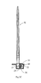
- FIG. 9A is a side view of an example fin, which can be used with a device or fin plug described herein;
- FIG. 9B is a top perspective view of the fin of FIG. 9A ;
- FIG. 9C is a bottom perspective view of the fin of FIG. 9A ;
- FIG. 9D is a front view of the fin of FIG. 9A ;
- FIG. 9E is a back view of the fin of FIG. 9A ;
- FIG. 9F is a cross-sectional view of the fin of FIG. 9A ;
- FIG. 9G is a top view of the fin of FIG. 9A ;
- FIG. 9H is a bottom view of the fin of FIG. 9A ;
- FIG. 10A is a side view of an example right-side fin, which can be used with a device or fin plug described herein;
- FIG. 10B is a cross-sectional view of the fin of FIG. 10A ;
- FIG. 10C is a back view of the fin of FIG. 10A ;
- FIG. 10D is a top perspective view of the fin of FIG. 10A ;
- FIG. 11A is a side view of an example left-side fin, which can be used with a device or fin plug described herein;
- FIG. 11B is a cross-sectional view of the fin of FIG. 11A ;
- FIG. 11C is a back view of the fin of FIG. 11A ;
- FIG. 11D is a top perspective view of the fin of FIG. 11A ;
- FIGS. 12A to 15D illustrate an alternative arrangement, in which the securing mechanism is incorporated in the fin base portion
- FIGS. 12A to 12C is a series of views showing construction and assembly of a cartridge incorporating the securing mechanism components, adapted for fitting into a fin base portion or other device;
- FIGS. 13A to 13D is a series of views showing the cartridge being installed into the base portion of a fin
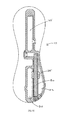
- FIGS. 14A to 14E are orthogonal views and an elevational section view of a fin incorporating the cartridge
- FIGS. 15A to 15C show the fin being installed in a water craft
- FIG. 15D is a section showing the off-centre position of the securing mechanism within the fin base, and the engagement with the fin plug;
- FIGS. 16A to 16C is a series of views showing construction and assembly of a fin in which a resilient biasing rod and protruding member are installed directly.
- FIGS. 1A and 1B An example of a securing mechanism incorporated in a device or fin plug 10 is shown in FIGS. 1A and 1B .
- the device 10 is used for holding a first fin portion 15 in a water craft, such as a surfboard or the like (not shown).
- the device 10 can be formed such that it is integral or insertable into the water craft.
- the device 10 can include a first cavity 20 , having a cavity wall 25 (and further described below).
- the device 10 also includes a resilient elongate member 30 , which can be located at least partially along an elongate side of the cavity wall 25 .
- FIG. 1 also shows that the resilient elongate member 30 can have an extending portion 35 , where the extending portion 35 extends from the resilient member 30 through a recess 40 or aperture in the elongate side of the cavity wall 25 ,
- any one or a combination of the resilient elongate member 30 and the extending portion 35 can apply a force to the first fin portion 15 to hold the first fin portion 15 within the first cavity 20 .
- the resilient elongate member 30 is a resilient rod or pin
- the extending portion 35 can includes a bulbous portion 45 , where the bulbous portion 45 is configured to engage with the first fin portion 15 .
- the bulbous portion 45 can be a part of a wheel-like member formed around the elongate rod 30 , where the wheel-like member 35 is configured to move around the rod 30 when engaging with the first fin portion 15 , to hold the first fin portion 15 in the first cavity 20 .
- FIGS. 1A and 1B show that the rod 30 is a pin, or the like, which can act as a spring to allow the wheel-like member 35 , to act as a barrel, which can hold the fin 50 in place.
- the device 10 can be in the form of a box which can hold the fin and hold the pin in place.
- FIG. 1 also shows that once the rod 30 is inserted into the device 10 , the insertion can be sealed by an end plug 55 , or the like. The plug 55 can prevent the rod 30 moving out of the device 10 .
- FIGS. 1A and 1B also show that the device 10 can include one or more caps 55 , 57 , 60 , which can be used to seal the extending portion 35 into the device 10 .
- the end cap 55 is typically water tight and can hold both the rod 30 and the extending portion 35 therein.
- the side cap 57 can be optional, the rod 30 and the extending portion 35 can be installed without the use of an aperture that side cap 57 seals.
- FIG. 6N illustrates an embodiment of the fin plug 10 without the use of a side cap 57 .
- the first fin portion 15 can also include a grooved portion 65 on a side fin surface 70 .
- the grooved portion 65 is typically configured to engage with the extending portion 35 .
- a surface of the wheel-like member 35 which is typically a curved surface, is configured to site within the grooved portion 65 .
- the grooved portion 65 can be formed or shaped such that it substantially conforms or mates with the curved surface of the extending portion 35 , strict conformance or mating is not necessary. In these examples, the grooved portion 65 is configured to roll over the extending portion 35 and the extending portion 35 can then lock the first fin portion 15 into the first cavity 20 . It will also be appreciated that when the locking action occurs and the first fin portion 15 is pushed into the cavity, the rod 30 may bend and may remain slightly bent when applying the force to the extending portion 35 , which subsequently applies a force to the grooved portion 65 , in order to maintain the first fin portion 15 within the first cavity 20 . In one particular example, either a lateral or a downward force, or a combination thereof can be applied to maintain the first fin portion 15 within the device 10 .
- a second fin portion 90 is inserted initially, where the recess 85 on the second fin portion 90 engages with the protrusion 80 on the device 10 (within the second cavity 75 ).
- the first fin portion 15 is locked into the first cavity 20 by pushing down on the fin 50 such that the groove 65 engages with the extending portion 35 , which is at least partially within the first cavity 20 .
- a fin plug 10 for installation in a water craft (not shown), said fin plug 10 including a first open cavity 20 adapted to receive a base portion 18 of a water craft fin 50 ; and, a resilient biasing rod 30 and a protruding member (otherwise referred to herein as an extending portion) 35 cooperating with the biasing rod 30 .
- the protruding member 35 is adapted/configured to abut the base portion 18 of said fin 50 when received in said first open cavity 20 .
- the biasing rod 30 and protruding member 35 are adapted to apply a force to the base portion 18 of said fin 50 to inhibit removal of said fin 50 from said first open cavity 20 .
- the biasing rod 30 when inserted into the fin plug 10 is located adjacent the first open cavity 20 .
- the biasing rod 30 extends substantially parallel to a side surface 16 of the base portion 18 of the fin 50 .
- the protruding member 35 can abut the side surface 16 .
- the fin plug 10 can also include a lateral cavity 22 where the biasing rod 30 is located within the lateral cavity 22 .
- the lateral cavity 22 and the first open cavity 20 are separated by an apertured wall (herein referred to as the cavity wall) and at a portion of the protruding member 35 protrudes through an aperture (or recess) 40 in the wall 25 into the first open cavity 20 .
- the side surface 16 can include an inclined surface section (otherwise described herein as a grooved portion) 65 .
- the inclined surface section 65 is adapted to cooperate with the protruding member 35 so as to cause a force, inwardly into the first open cavity 20 to be applied to the base portion 18 under the influence of the biasing rod 30 .
- the fin plug 10 can have a forward region 12 and a rearward region 14 .
- the protruding member 35 is typically located in the rearward region 14 .
- the fin plug 10 can include an additional fin removal inhibiting means located in the forward region 12 .
- the fin removal inhibiting means can include a fin engagement means which includes a ledge portion (referred to herein as the protrusion) 80 which is adapted to overlie a fin section (referred to herein as the recess) 85 and to inhibit movement of the fin 50 when the base portion 18 is received within the first open cavity 20 .
- the fin plug 10 can include a second open cavity 75 .
- the first open cavity 20 can receive a first tab of the base portion 18 of the fin 50 and the second open cavity 75 can receive a second tab of the base portion 18 of the fin 50 .
- the first open cavity 20 is located in the rearward region 14 and the second open cavity is located in the forward region 12 .
- the inclined surface section 65 of the base portion of said fin is located on the first tab.
- the ledge portion 80 can be located within said second open cavity, and the fin section can be located on the second tab of the base portion of the fin 50 .
- the ledge portion can include a ledge extending from one end of said second open cavity and defining a recess between said ledge and a base surface of said second open cavity, said recess being adapted to receive the fin section, for example as shown in FIGS. 12A to 12H of WO 2014/008529.
- the extending portion/protruding member 35 can be wheel-like or a ring-shaped member located about the biasing rod 30 .
- the ring-shaped member can rotate about said biasing rod.
- the ring-shaped member does not necessarily have to be cylindrical in shape and may have a circumferential outer surface extending between two side surfaces, where the circumferential outer surface has a convex profile between said side surfaces.
- the device 10 can also include a second cavity 75 .
- the second cavity 75 can include a protrusion 80 , where the protrusion 80 is configured to be inserted into and mate with a respective recess 85 of a second fin portion 90 , to thereby hold the second fin portion 90 within the second cavity 75 .
- any one or a combination of the protrusion 80 and the recess 85 ; and, the extending portion 35 and the first fin portion 15 can snap-lock together, and the fin 50 can be held robustly within the device 10 .
- the second fin portion 90 can be held within the second cavity 75 by a number of different mechanical elements/fixing means. Further examples of fixing means for fixing/holding the second fin portion 90 into a second cavity 75 are described below.
- the first cavity 15 and the second cavity 75 are two distinct cavities within the device 10 . However, it will be appreciated that they may in some instances form a part of one elongate cavity (not shown). Notably, certain advantages may be provided by maintaining the two distinct cavities. That is, the bridge 95 between the two cavities can be configured to more robustly hold the first and second fin portions 15 , 90 in respective first and second cavities 20 , 75 . Furthermore, the bridge can include a bridge section which has an upper surface which is adapted to abut a lower surface of a water craft fin.
- a surfboard may include a central fin and two side fins (referred to herein as left and right fins, when viewing the underside of the surfboard with tail of the surfboard lowermost).
- left and right fins when viewing the underside of the surfboard with tail of the surfboard lowermost.
- the features described herein may be applicable to any fin, the water craft may include slight variations depending on the location of the fin (whether a central fin, right fin, or left fin).
- FIGS. 2A to 3C represent an example of a central fin 50 , where, as shown in FIG. 2C , the fin 50 is substantially perpendicular to the device 10 .
- the fins 50 of FIGS. 4C and 5C are at an angle to the vertical of the device 10 .
- FIG. 4C is an example of a right-side fin
- FIG. 5C is an example of a left side fin.
- the device 10 may also be varied to accommodate for the varying angle of insertion.
- the first cavity 15 may include an angled opposing wall 28 , opposite to the cavity wall 25 (which is typically cavity wall where the extending portion 35 protrudes there through).
- FIGS. 6A to 6P show example of a device or fin plug 10 , where in these examples, the device 10 would typically be used for a centre fin.
- the extending portion 35 protrudes through the cavity wall 25 at a position where it can easily mate with the corresponding grooved portion 65 of the fin 50 .
- the extending portion 35 need not necessarily protrude through at the centre of the cavity wall 25 , and can, according to this particular example, be offset from the centre.
- the device 10 shows fixation points 98 for fixing of grub screws or any other suitable fixing means, or the like, for further fixing the fin 50 to the device 10 .
- the use of the grub screws or other suitable fixing means can allow for different types of fins to be fixed to the device 10 .
- the grub screw can be configured to extend into the first cavity 20 to further secure a base portion of the fin 50 within the first cavity 20 .
- a similar grub screw can be used for the second cavity 75 where a grub screw is configured to extend into the second cavity 75 to further secure a tab, base portion, or the like of the fin 50 into the second cavity 75 .
- FIGS. 7A to 7D are examples of the device 10 for use with a right side fin.
- FIGS. 8A to 8D are examples of the device 10 for use with a left side fin.
- the examples show that the devices when used for the side fins (such as the left and right fins) can be formed such that they are mirror images of each other.
- FIGS. 7B and 8B show the angled opposing wall 28 , to allow for an angled insertion of the respective fins.
- the device 10 is shaped substantially as a figure-eight, such that at least one profile of the device has substantially, a figure-eight shape.
- the first cavity 15 is located or formed within a first end 12 of the figure-eight and the second cavity 75 is formed within the second end 14 of the figure-eight.
- the figure-eight shape of the device 10 can provide advantages such allowing for the device 10 to form part of the water craft and further allowing the fin portions to be locked therein.
- the smooth edges of the figure-eight shape can also provide for an easier manufacturing process.
- the device is not limited to this shape and other shapes which provide the functionality of the cavities, are incorporated herein.
- FIGS. 9A to 9H show examples of a centre fin 50 , for use with a centre device 10 .
- FIGS. 10A to 10D show examples of a right fin 50
- FIGS. 11A to 11D show an example of a left fin 50 .
- the left and right fins may be mirror images of each other.
- first fin portion 15 and the second fin portion 90 can be or can include first and second tabs respectively, it will be appreciated that any base portion of the fin 50 may be configured to be insertable into the first and second cavities 20 , 75 .
- FIGS. 12A to 15D , and FIGS. 16A to 16C illustrate two different embodiments of securing mechanism being incorporated in a fin of the water craft.
- the securing mechanism is formed in a cartridge 4000 , or cassette, which is installed in the base portion 4018 of a fin 4050 .
- the cartridge is illustrated in FIGS. 12A to 12C in sequence of assembly.
- Cartridge 4000 consists of an outer cartridge body 4002 which provides a support framework for the resilient biasing rod 4030 and wheel-like protruding member 4035 , which when assembled sit within a side-opening cavity 4004 of the cartridge, the cavity having a wider central portion 4006 to accommodate the member 4030 .
- end holes 4008 and 4009 which act to support the ends of the biasing rod, with one of the end holes 4008 being a through hole to allow insertion of the rod during cartridge assembly.
- the other end hole 4009 may be either a through hole or a blind hole.
- the wheel-like protruding member has a diameter preferably matching the width of the cartridge body 4002 and the biasing rod 4030 is supported in the cartridge with its axis off-centre, so that part of the protruding member 4035 extends beyond the side of the cartridge and, when installed, beyond the side of the fin base portion.
- the construction of the resilient rod 4030 and of the wheel-like protruding member 4035 may be similar to those described above, for example with reference to FIGS. 1A and 1B .
- the cartridge body 4002 may be formed with perforations 4012 to reduce weight, and may be formed of any suitable material, and by any suitable means, for example molded from plastics material such as Glass-filled Nylon, ABS, Acetal.
- FIGS. 13 A to 13 D show installation of the cartridge into the base portion 4018 of a fin 4050
- FIGS. 14A to 14E illustrate a fin 4050 with the securing mechanism cartridge 4000 installed in the fin base.
- the rear of the fin base portion 4018 includes a large elongated cavity 4014 for receiving the cartridge, which may be secured in place by a friction/interference fit or alternatively glued or welded in place.
- the smaller cavities 4016 in the fin base portion 4018 serve to reduce weight.
- the width of the cartridge is preferably no wider than that of the fin base into which it is installed, except for the upper profile of the cartridge which preferably has a width slightly greater than the corresponding with of the slot so that when these parts meet there is an interference fit. This creates a tighter fit between fin base and slot, which reduces fin base wobble (which is a desired attribute in smoothly transferring the energy of the surfer to the fin).
- a transverse pin 4019 projecting at both sides of the fin base, for engaging with tracks in the side surfaces of the fin plug to secure the front of the fin in the fin plug.
- FIGS. 15A to 15C show a sequence for installing the fin of FIGS. 13A to 14E in the fin plug of a surf craft.
- the fin is inserted in the fin plug at an angle, so that the projecting portions of the transverse pin 4019 are fed into the longitudinal tracks 4021 in both sides of the fin plug cavity.
- the fin is then moved forward, moving the pin 4019 along the tracks 4021 , until the front of the fin base portion reaches the desired location within the fin plug cavity. Then the rear of the fin is pivoted down ( FIG. 15B ) to engage the securing mechanism. As the wheel-like protruding member 4035 of the mechanism contacts the side surface 4023 of the fin plug cavity 4020 , the rod 4030 resiliently flexes to allow the member 4035 to ride inwards and to snap fit into an undercut lateral recess 4065 formed in the side surface of the fin plug cavity ( FIG. 15D ).
- the resilient rod 4030 will remain slightly bent when the fin is fully inserted, the spring force thus provided by the rod 4030 helping to retain the member 4035 firmly in the undercut recess to keep the fin secured to the fin plug.
- the engagement of member 4035 with the undercut recess may also provide a downwards force vector on the fin, forcing the bottom surface of the fin base against the base of the fin plug cavity and retaining the slightly tapered cartridge in interference fit engagement with the sides of the fin plug cavity. This aids stability of the fin engagement in the water craft.
- the rear of the fin is pivoted upwards to again flex the rod 4030 and ‘snap’ the securing mechanism out of the fin plug cavity, in essentially the opposite sequence to the insertion sequence of FIGS. 15A to 15C .
- the rod 4030 is pivoted upwards to again flex the rod 4030 and ‘snap’ the securing mechanism out of the fin plug cavity, in essentially the opposite sequence to the insertion sequence of FIGS. 15A to 15C .
- This cartridge embodiment has the advantage that the cartridge may be adapted for installation in a variety of different fin configurations, or in other devices such as storage hooks, with less tooling expense.
- FIGS. 16A to 16C show an alternative example embodiment, in which the resilient rod 4030 and protruding member 4035 of the securing mechanism are installed directly in the fin base portion 4018 , rather than in a cartridge installed in the fin base. Otherwise, the construction and operation of the embodiment of FIGS. 16A to 16C are similar to that of FIGS. 13A to 15D .
- FIGS. 12A to 16C use a transverse pin 4019 engaging with the longitudinal tracks 4021 to secure the front of the fin base in the fin plug cavity. It will be appreciated that the disclosure extends to other mechanisms to perform this function, including for example an arrangement similar to the recess 85 and protrusion 80 of FIGS. 1A to 11D , or a recess formed between a ledge and a base surface of the fin plug cavity, adapted to receive the fin section, for example as shown in FIGS. 12A to 12H of WO 2014/008529.
- the fin plug of the first aspect of this invention is primarily intended to be used with water craft fins (e.g. surfboard fins) of the second aspect of this invention, so as to enable such fins to be easily and conveniently attached to, or detached from the fin plug (without the use of a tool), it is not limited to such use.
- other water craft attachment devices can be selectively attached to, or detached from, the relevant fin plug in substantially the same way as the abovementioned fins are attached or detached.
- FIGS. 29A to 29H of WO 2014/008529 An example of such other water craft attachment devices is a hanger/hook device, not shown, for example generally as described and shown in FIGS. 29A to 29H of WO 2014/008529.
- this hook device is adapted to be connected to a surfboard (or other water craft) so that the surfboard (or other water craft) can be suspended from a horizontal supporting rod (or similar structure).
- the base portion of the hook device may be configured to receive a securing mechanism cartridge for example as shown in FIGS. 12A to 12C , or alternatively to receive directly a biasing rod and protruding member in similar arrangement to the fin base shown in FIGS. 16A to 16C .
- the fin plug 10 can be formed of ABS (Acrylonitrile Butadiene Styrene, or any other plastics) or Zytel.
- the rod 30 or 4030 is typically formed of any elastic material such as high grade stainless steel or titanium, which is also a robust material in watercraft as the material does not generally degrade or rust. The same robust material may also be used for the extending portion 35 or 4035 . It will further be appreciated that the device 10 can be injection molded.
- the cartridge body may also be formed of many different materials.
- the cartridge body will be injection molded plastics, with (Glass-filled Nylon, ABS, Acetal being examples of preferred materials.
- the described hook device can be formed from many different materials. Typically, this device will be formed from appropriate plastic materials which are relatively inexpensive and sufficiently strong for suspending a surfboard (or other water craft) from a supporting rod.
Landscapes
- Chemical & Material Sciences (AREA)
- Engineering & Computer Science (AREA)
- Combustion & Propulsion (AREA)
- Mechanical Engineering (AREA)
- Ocean & Marine Engineering (AREA)
- Connector Housings Or Holding Contact Members (AREA)
- Toys (AREA)
- Closures For Containers (AREA)
- Thermotherapy And Cooling Therapy Devices (AREA)
- Prostheses (AREA)
- Fishing Rods (AREA)
Abstract
A securing arrangement for securing a water craft fin to a water craft having a fin plug, the fin plug having a first open cavity configured to receive a base portion (4018) of the water craft fin. The securing arrangement includes a resilient biasing rod (4030) and a protruding member (4035) cooperating with the biasing rod (4030). The protruding member (4035) is adapted to actuate when the base portion (4018) of the fin is inserted into the first open cavity of the fin plug so that the biasing rod (4030) and the protruding member (4035) inhibit removal of the fin from the first open cavity.
Description
This is a continuation-in-part application of both Patent Application Number PCT/AU2015/050092, filed Mar. 9, 2015, and U.S. patent application Ser. No. 14/411,667, filed Dec. 29, 2014. The priority of both applications is hereby claimed, and both applications are incorporated herein by reference. Application Number PCT/AU2015/050092 claims the priority of Australian Patent Application Number 2014900816 filed Mar. 11, 2014. U.S. patent application Ser. No. 14/411,667 is a national stage entry of Application Number PCT/AU2013/000738, filed Jul. 5, 2013, which claims the priority of Australian Patent Application Number 2012902939 filed Jul. 9, 2012.
The present invention relates to a securing arrangement for securing a water craft fin to a water craft having a fin plug, for installation in a water craft, such as a surfboard or the like, adapted to enable fins to be removably attached to the water craft.
The present invention also relates to fins or other items which are adapted to be removably attached to water craft.
A water craft, such as a surfboard, particularly one on which a person stands, kneels or sits, when traversing water or riding a wave, generally has at least one fin in an underside of the water craft, generally near the tail end of the water craft. Such fins have a number of functions, including: enabling the craft to travel in a desired direction; facilitating the turning of the craft; preventing the craft from slipping sideways; and providing greater control over the movement of the craft, such as when riding a wave.
The following discussion is directed mainly to surfboards but it is to be understood that the discussion applies equally to other water craft (and surf craft) which are adapted to include fins, such as sail boards, paddle boards, rescue boards, surf skis, kayaks, and the like.
Some surfboards have fins integrally formed in the underside of the surfboard and, historically, most surfboards included such integrally formed fins. These integrally formed fins are generally ‘glassed in’, meaning that they are formed as part of the surfboard by means of fiber-reinforced resin. The formation of such ‘glassed in’ fins is quite labour intensive and it makes the subsequent sanding and finishing of the board more difficult.
In the last twenty years or so, it has become more common for surfboards to incorporate fin systems which include removable fins. Such fin systems have numerous benefits, including: enabling the fins to be removed whilst travelling; allowing damaged fins to be easily replaced; and enabling fins of different shapes or styles to be selectively used. These fin systems typically include at least one fin plug embedded in the underside of the surfboard, adapted to receive at least one surfboard fin. Each such fin plug will generally include an open cavity adapted to receive a base portion (or base element) of a surfboard fin. The fin is then able to be removably attached to the surfboard by inserting the relevant base portion (or base element) of the fin into the cavity (or cavities) of the fin plug (or fin plugs). There are numerous known fin systems which incorporate such an arrangement.
One known and commonly used fin system is described in U.S. Pat. No. 5,464,369 in the name of Fin Control Systems Pty Ltd. This system includes fins, each having two projecting base elements (or tabs) and, for each fin, two fin plugs installed in the underside of the surfboard. Each of the fin plugs has a cavity for receiving one of the base elements. Each fin plug also includes a grub screw for securing the base element within the cavity of the fin plug.
The above fin system of U.S. Pat. No. 5,464,369 has become exceedingly popular and widely used as the system enables fins to be affixed to a surfboard in a highly secure manner whilst also enabling the fins to be easily removed from the surfboard when desired. However, one drawback of the abovementioned system is that the installation and removal of fins from the fin plugs is somewhat time-consuming and requires the use of a tool (e.g. an Allen key) as the grub screws need to be threaded into or out of each cavity in order to secure or release the base elements of each fin (as desired).
Another fin plug which functions in a similar way to that described above is the fin plug assembly described in PCT/AU/2008/001132, also in the name of Fin Control Systems Pty Ltd. The fin plug described in PCT/AU/2008/001132 includes two open cavities adapted to receive corresponding base elements of a surfboard fin. These base elements are adapted to be secured and released by means of grub screws (which can be threaded into or out of the cavities). Each such grub screw is adapted to press laterally against a side of a base element of the fin to secure it in position.
Other known fin systems include systems which incorporate a single fin plug, with a single cavity, for each surfboard fin. Typically, such a fin system has quite a large fin plug with an elongated fin cavity for receiving the base element(s) of a fin. In such fin systems it is again usual for each fin to be secured to the surfboard (that is, the base element of the fin to be secured within the cavity of the fin plug) by means of a grub screw arrangement, such as that mentioned above. There is a present need for a water craft fin securing mechanism adapted to enable fins to be removably secured to the underside of a water craft in a quick, easy and secure manner and preferably without the need for using a tool.
International Patent Application PCT/AU2013/000738 (WO 2014/008529) by the present Applicant discloses a securing mechanism for securing a water craft fin, hook or similar to a water craft, including a securing arrangement comprising a resilient biasing rod and a protruding member cooperating with the biasing rod. The protruding member actuates when the base portion of said fin when received in said first open cavity so that the biasing rod and protruding member apply a force to the base portion of said fin to inhibit removal of the fin from the open cavity.
International Patent Application PCT/AU2013/001314 by the present Applicant discloses a modified fin plug construction providing an improved bond with the water craft, and in some embodiments may employ the fin securing mechanism of WO 2014/008529.
The present disclosure aims to build on the disclosure of WO 2014/008529 to provide alternative forms of securing mechanisms.
The contents of WO 2014/008529 and PCT/AU2013/001314 are incorporated herein by reference.
Further, the present invention is directed towards fins or other items which are adapted to be easily and quickly secured to or removed from the abovementioned fin plugs without the use of a tool.
In this specification, where a document, act or item of knowledge is referred to or discussed, this reference or discussion is not an admission that the document, act or item of knowledge or any combination thereof was at the priority date:
-
- a) part of the common general knowledge; or
- b) known to be relevant to an attempt to solve any problem with which this specification is concerned.
Any reference herein to known prior art does not, unless the contrary indication appears, constitute an admission that such prior art is commonly known by those skilled in the art to which the invention relates, at the priority date of this application.
According to a first form of the present disclosure, there is provided a securing arrangement for securing a water craft fin to a water craft having a fin plug, the fin plug having a first open cavity adapted to receive a base portion of the water craft fin; the securing arrangement comprising a resilient biasing rod and a protruding member cooperating with the biasing rod, said protruding member being adapted to actuate when the base portion of said fin when received in said first open cavity so that the biasing rod and protruding member apply a force to the base portion of said fin to inhibit removal of said fin from said first open cavity.
The biasing rod may extend substantially parallel to a side surface of the base portion of said fin.
In a first example form, the biasing rod and protruding member are incorporated in the fin, preferably in a base portion of the fin, to cooperate with a fin plug of the water craft.
The biasing rod and protruding member may be incorporated in a cartridge assembly which is fitted in a cavity formed in the fin base. Preferably the cartridge assembly includes a cartridge body with a cavity in which the biasing rod and protruding member are supported.
In a further example form, the invention provides a fin adapted for installation in a fin plug of a water craft, said fin plug including a first open cavity adapted to receive a base portion of the water craft fin, wherein the fin includes:
-
- a resilient biasing rod and a protruding member cooperating with the biasing rod, said protruding member being adapted to protrude from the fin base portion when actuated by the biasing rod, to engage with the fin plug and apply a force to the base portion of said fin to inhibit removal of said fin from said first open cavity.
The biasing rod generally extends substantially parallel to a side surface of the base portion of said fin. It is preferred that the orientation of the biasing rod is also substantially parallel to the plane of the water craft.
The biasing rod may be formed of any suitable material, such as titanium, steel (e.g. marine grade steel), fiberglass, carbon fibre or plastic (including reinforced engineering plastic). It is particularly preferred that the biasing rod is formed of titanium.
The protruding member is preferably adapted to abut a side surface of the fin plug cavity.
In a particularly preferred embodiment, a side surface of the first cavity of the fin plug includes a lateral recess portion being adapted to co-operate with the protruding member so as to retain the fin in the fin plug cavity. Preferably, the biasing rod will cause the protruding member to ‘snap-fit’ into the lateral recess of the fin plug cavity when the fin base portion is pushed into the cavity.
The fin and fin plug will typically have a forward region and a rearward region and the fin plug will preferably include additional fin removal inhibiting means located in said forward region. Preferably, the protruding member is located in the rearward region.
The additional fin removal inhibiting means preferably includes fin engagement means. The fin engagement means preferably includes a slot or groove to receive a lateral projection such as a transverse pin on a forward portion of the fin base.
In another form of the disclosure, the securing mechanism may be incorporated in the fin plug, generally as described in WO 2014/008529.
In a particularly preferred embodiment, the protruding member is a ring-shaped member located about said biasing rod. Preferably, this ring-shaped member is adapted to rotate about said biasing rod. The ring-shaped member preferably has a circumferential outer surface extending between two side surfaces, said circumferential outer surface having a convex profile between said side surfaces. This convex profile enables the load or force, which is applied to the ring-shaped member when it engages with the side surface of the water craft fin plug, to be dispersed more evenly across the ring shaped member. The ring shaped member preferably rolls or rotates so as to reduce friction wear on the plug and facilitate a “smoother” installation and removal of the fin from the plug.
The ring-shaped member is typically formed of a durable, non-corrosive polymer/plastic material (although a number of other suitable materials could be used). Acetal is a particularly preferred material for the ring-shaped member. Acetal is a common term for a comparatively hard engineering plastic with high tensile strength, suitable for machining and high rigidity in use.
Typically, the embodiments of this invention where the biasing rod and protruding member are formed in the fin are adapted for installation in a larger surf craft, such as a longboard or a stand-up paddle board, which will typically have relatively thick fins with thicker fin base portions to accommodate the mechanism. However, the fin-mounted embodiment may be used for relatively smaller shortboard fins as well, for example with adaption of the fin base portion to be thicker than the body of the fin, with corresponding change in breadth of the cavity of the fin plug. According to a second aspect of the present disclosure, there is provided a water craft fin plug adapted to receive a fin plug according to the above embodiment of the disclosure.
According to a third aspect of this disclosure, there is provided fin plug and a water craft fin kit, for use in a surf craft, including a fin plug as described above and a water craft fin as described above.
According to a fourth aspect of the present disclosure, there is provided a water craft attachment device having a base portion including a securing mechanism as described above.
In a preferred embodiment, the water craft attachment device includes a support connecting element for connecting the attachment device to a support structure. This support connecting element may include a hook element for connecting the water craft attachment device to a support rod (e.g. a horizontal support rod). The support connecting element, such as a hook element, may be separated from the base portion of the water craft attachment device by an intermediate section of the attachment device.
In a further, particularly preferred embodiment of this aspect of the invention, the hook element lies in a plane which is at right angles to the plane of the base portion.
Typically, the water craft attachment device described above will be adapted for use in a surfboard or other surf craft.
The above preferred embodiment of the fourth aspect of the present disclosure enables a water craft attachment device, which includes a hook element, to be attached to a surfboard (or other water craft), which then enables the surfboard (or other water craft) to be suspended from a supporting rod (e.g. a horizontal support rod). In the abovementioned preferred embodiment, in which the hook element lies in a plane which is at right angles to the plane of the base portion, this enables a multitude of surfboards to be suspended from the supporting rod in a sandwiched formation, thereby enabling a greater number of surfboards to be stored on the supporting rod.
As will be appreciated from the above discussion (and as further explained and illustrated later in this specification), a water craft fin or other water craft attachment device, according to the above relevant descriptions, can readily be attached to a fin plug, according to the above relevant description.
This attachment is effected, in the case of a water craft fin, by inserting the base portion of the fin into the first open cavity of the fin plug. This is typically achieved by engaging a forward portion of the fin (e.g. the fin section) with the fin engagement means of the fin plug and then rotating a rearward portion of the fin down towards the fin plug, so that the base portion of the fin extends into the open cavity, thereby enabling the protruding means of this base portion to protrude into lateral recess of the fin plug cavity.
In the case of another water craft attachment device, such as a hook element (as described above), the attachment is effected by inserting the base portion of the attachment device into the first open cavity of the fin plug. This is typically achieved by engaging a forward portion of the attachment device with the fin engagement means of the fin plug and then rotating a rearward portion of the attachment device down towards the fin plug, so that the securing mechanism of the base portion of the attachment device operates as described above
In the above embodiments, the biasing rod and protruding member may be respectively a resilient elongate member a bulbous portion. The bulbous portion can be part of a wheel-like member formed around the elongate rod, the wheel-like member being configured to rotate about the rod when the fin and fin plug engage, during installation and/or removal of the fin, to hold the fin base portion in the fin plug cavity once the fin is installed.
The biasing rod and protruding member will be incorporated in one of the fin or the fin plug, with the other of the fin or the fin plug having a grooved portion (or an inclined portion), the grooved portion (or inclined portion) being configured to engage with the extending portion.
A surface of the wheel-like member can be is configured to sit within the grooved portion (or against the inclined portion).
Further forms and embodiments of the disclosure will also be apparent from the description and drawings, and from the claims.
It will be appreciated that the features described herein can be provided in the device described herein either independently or in different combinations.
A detailed description of a preferred embodiment of a securing mechanism incorporated in device/fin plug according to the first aspect of this invention is given hereinafter, while referring to the following figures:
An example of a securing mechanism incorporated in a device or fin plug 10 is shown in FIGS. 1A and 1B .
In this particular example, the device 10 is used for holding a first fin portion 15 in a water craft, such as a surfboard or the like (not shown). The device 10 can be formed such that it is integral or insertable into the water craft.
As shown in FIGS. 1A and 1B , the device 10 can include a first cavity 20, having a cavity wall 25 (and further described below). The device 10 also includes a resilient elongate member 30, which can be located at least partially along an elongate side of the cavity wall 25. FIG. 1 also shows that the resilient elongate member 30 can have an extending portion 35, where the extending portion 35 extends from the resilient member 30 through a recess 40 or aperture in the elongate side of the cavity wall 25,
Accordingly, when the first fin portion 15 is inserted into the first cavity 20, any one or a combination of the resilient elongate member 30 and the extending portion 35 can apply a force to the first fin portion 15 to hold the first fin portion 15 within the first cavity 20.
Thus, in one particular example, the resilient elongate member 30 is a resilient rod or pin, and the extending portion 35 can includes a bulbous portion 45, where the bulbous portion 45 is configured to engage with the first fin portion 15. In yet a further example, the bulbous portion 45 can be a part of a wheel-like member formed around the elongate rod 30, where the wheel-like member 35 is configured to move around the rod 30 when engaging with the first fin portion 15, to hold the first fin portion 15 in the first cavity 20.
Additionally, FIGS. 1A and 1B also show that the device 10 can include one or more caps 55, 57, 60, which can be used to seal the extending portion 35 into the device 10. In one particular example, the end cap 55 is typically water tight and can hold both the rod 30 and the extending portion 35 therein. The side cap 57 can be optional, the rod 30 and the extending portion 35 can be installed without the use of an aperture that side cap 57 seals. FIG. 6N illustrates an embodiment of the fin plug 10 without the use of a side cap 57.
According to yet a further example, the first fin portion 15 can also include a grooved portion 65 on a side fin surface 70. The grooved portion 65 is typically configured to engage with the extending portion 35. Thus, in one example, a surface of the wheel-like member 35, which is typically a curved surface, is configured to site within the grooved portion 65.
It will be appreciated that although the grooved portion 65 can be formed or shaped such that it substantially conforms or mates with the curved surface of the extending portion 35, strict conformance or mating is not necessary. In these examples, the grooved portion 65 is configured to roll over the extending portion 35 and the extending portion 35 can then lock the first fin portion 15 into the first cavity 20. It will also be appreciated that when the locking action occurs and the first fin portion 15 is pushed into the cavity, the rod 30 may bend and may remain slightly bent when applying the force to the extending portion 35, which subsequently applies a force to the grooved portion 65, in order to maintain the first fin portion 15 within the first cavity 20. In one particular example, either a lateral or a downward force, or a combination thereof can be applied to maintain the first fin portion 15 within the device 10.
According to one particular example, when inserting the fin 50 into the device 10, a second fin portion 90 is inserted initially, where the recess 85 on the second fin portion 90 engages with the protrusion 80 on the device 10 (within the second cavity 75). Once the second fin portion 90 is in place, the first fin portion 15 is locked into the first cavity 20 by pushing down on the fin 50 such that the groove 65 engages with the extending portion 35, which is at least partially within the first cavity 20.
Thus, in a further example, referring to FIGS. 1A and 1B , there is provided herein a fin plug 10 for installation in a water craft (not shown), said fin plug 10 including a first open cavity 20 adapted to receive a base portion 18 of a water craft fin 50; and, a resilient biasing rod 30 and a protruding member (otherwise referred to herein as an extending portion) 35 cooperating with the biasing rod 30. The protruding member 35 is adapted/configured to abut the base portion 18 of said fin 50 when received in said first open cavity 20. Accordingly, the biasing rod 30 and protruding member 35 are adapted to apply a force to the base portion 18 of said fin 50 to inhibit removal of said fin 50 from said first open cavity 20.
As shown in FIGS. 1A and 1B , the biasing rod 30, when inserted into the fin plug 10 is located adjacent the first open cavity 20. According to one particular example, the biasing rod 30 extends substantially parallel to a side surface 16 of the base portion 18 of the fin 50. Thus, the protruding member 35 can abut the side surface 16.
It will further be appreciated that the fin plug 10 can also include a lateral cavity 22 where the biasing rod 30 is located within the lateral cavity 22. Thus, the lateral cavity 22 and the first open cavity 20 are separated by an apertured wall (herein referred to as the cavity wall) and at a portion of the protruding member 35 protrudes through an aperture (or recess) 40 in the wall 25 into the first open cavity 20.
The side surface 16 can include an inclined surface section (otherwise described herein as a grooved portion) 65. The inclined surface section 65 is adapted to cooperate with the protruding member 35 so as to cause a force, inwardly into the first open cavity 20 to be applied to the base portion 18 under the influence of the biasing rod 30.
According to one particular example, the fin plug 10 can have a forward region 12 and a rearward region 14. The protruding member 35 is typically located in the rearward region 14.
The fin plug 10 can include an additional fin removal inhibiting means located in the forward region 12. The fin removal inhibiting means can include a fin engagement means which includes a ledge portion (referred to herein as the protrusion) 80 which is adapted to overlie a fin section (referred to herein as the recess) 85 and to inhibit movement of the fin 50 when the base portion 18 is received within the first open cavity 20.
As described herein, the fin plug 10 can include a second open cavity 75. Accordingly, the first open cavity 20 can receive a first tab of the base portion 18 of the fin 50 and the second open cavity 75 can receive a second tab of the base portion 18 of the fin 50. In this particular example, the first open cavity 20 is located in the rearward region 14 and the second open cavity is located in the forward region 12. Furthermore, the inclined surface section 65 of the base portion of said fin is located on the first tab. Additionally, the ledge portion 80 can be located within said second open cavity, and the fin section can be located on the second tab of the base portion of the fin 50.
The ledge portion can include a ledge extending from one end of said second open cavity and defining a recess between said ledge and a base surface of said second open cavity, said recess being adapted to receive the fin section, for example as shown in FIGS. 12A to 12H of WO 2014/008529.
As discussed herein, the extending portion/protruding member 35 can be wheel-like or a ring-shaped member located about the biasing rod 30. In one particular example, the ring-shaped member can rotate about said biasing rod. In yet a further example, the ring-shaped member does not necessarily have to be cylindrical in shape and may have a circumferential outer surface extending between two side surfaces, where the circumferential outer surface has a convex profile between said side surfaces.
In yet a further example, as particularly shown in FIGS. 2A, 3A, 4A, 4F, 5A, and 5F , the device 10 can also include a second cavity 75. The second cavity 75 can include a protrusion 80, where the protrusion 80 is configured to be inserted into and mate with a respective recess 85 of a second fin portion 90, to thereby hold the second fin portion 90 within the second cavity 75.
Thus, for example, any one or a combination of the protrusion 80 and the recess 85; and, the extending portion 35 and the first fin portion 15 can snap-lock together, and the fin 50 can be held robustly within the device 10.
Notably, it will be appreciated by persons skilled in the art that the second fin portion 90 can be held within the second cavity 75 by a number of different mechanical elements/fixing means. Further examples of fixing means for fixing/holding the second fin portion 90 into a second cavity 75 are described below.
In the examples shown in the FIGS, the first cavity 15 and the second cavity 75 are two distinct cavities within the device 10. However, it will be appreciated that they may in some instances form a part of one elongate cavity (not shown). Notably, certain advantages may be provided by maintaining the two distinct cavities. That is, the bridge 95 between the two cavities can be configured to more robustly hold the first and second fin portions 15, 90 in respective first and second cavities 20, 75. Furthermore, the bridge can include a bridge section which has an upper surface which is adapted to abut a lower surface of a water craft fin.
It will be appreciated by persons skilled in the art that many water crafts such as surfboards or the like can include one or more fins. In one particular example, a surfboard may include a central fin and two side fins (referred to herein as left and right fins, when viewing the underside of the surfboard with tail of the surfboard lowermost). Thus, although the features described herein may be applicable to any fin, the water craft may include slight variations depending on the location of the fin (whether a central fin, right fin, or left fin).
An example of a variation can be seen when comparing FIGS. 2C, 4C , and 5C. In these examples, FIGS. 2A to 3C represent an example of a central fin 50, where, as shown in FIG. 2C , the fin 50 is substantially perpendicular to the device 10. However, in contrast, the fins 50 of FIGS. 4C and 5C , are at an angle to the vertical of the device 10. FIG. 4C is an example of a right-side fin, and FIG. 5C is an example of a left side fin. Although the fins described are configured to be inserted at any angle to the vertical, in one particular example, the angle is 7 to 9 degrees from the vertical.
Accordingly, the device 10 may also be varied to accommodate for the varying angle of insertion. As shown in FIGS. 4C and 5C , the first cavity 15 may include an angled opposing wall 28, opposite to the cavity wall 25 (which is typically cavity wall where the extending portion 35 protrudes there through).
In further examples, FIGS. 6A to 6P show example of a device or fin plug 10, where in these examples, the device 10 would typically be used for a centre fin. It will be appreciated by persons skilled in the art that, as shown in FIG. 6N , the extending portion 35 protrudes through the cavity wall 25 at a position where it can easily mate with the corresponding grooved portion 65 of the fin 50. Thus, the extending portion 35 need not necessarily protrude through at the centre of the cavity wall 25, and can, according to this particular example, be offset from the centre.
Additionally, the device 10 shows fixation points 98 for fixing of grub screws or any other suitable fixing means, or the like, for further fixing the fin 50 to the device 10. It will be appreciated that the use of the grub screws or other suitable fixing means can allow for different types of fins to be fixed to the device 10. Thus in this particular example, the grub screw can be configured to extend into the first cavity 20 to further secure a base portion of the fin 50 within the first cavity 20. A similar grub screw can be used for the second cavity 75 where a grub screw is configured to extend into the second cavity 75 to further secure a tab, base portion, or the like of the fin 50 into the second cavity 75.
In the examples shown herein, the device 10 is shaped substantially as a figure-eight, such that at least one profile of the device has substantially, a figure-eight shape. In these examples, the first cavity 15 is located or formed within a first end 12 of the figure-eight and the second cavity 75 is formed within the second end 14 of the figure-eight.
It will be appreciated by persons skilled in the art that the figure-eight shape of the device 10 can provide advantages such allowing for the device 10 to form part of the water craft and further allowing the fin portions to be locked therein. The smooth edges of the figure-eight shape can also provide for an easier manufacturing process. However, it will be appreciated that the device is not limited to this shape and other shapes which provide the functionality of the cavities, are incorporated herein.
Notably, referring to the fins 50, it will further be appreciated that although the first fin portion 15 and the second fin portion 90 can be or can include first and second tabs respectively, it will be appreciated that any base portion of the fin 50 may be configured to be insertable into the first and second cavities 20, 75.
Further variants of the securing fin plug arrangement are disclosed in WO 2014/008529, the contents of which are incorporated by reference.
In FIGS. 12A to 15D , the securing mechanism is formed in a cartridge 4000, or cassette, which is installed in the base portion 4018 of a fin 4050.
The cartridge is illustrated in FIGS. 12A to 12C in sequence of assembly.
At the ends of the cavity are end holes 4008 and 4009 which act to support the ends of the biasing rod, with one of the end holes 4008 being a through hole to allow insertion of the rod during cartridge assembly. The other end hole 4009 may be either a through hole or a blind hole.
As better seen in FIGS. 13A to 13C and in section views 14D and 15D, the wheel-like protruding member has a diameter preferably matching the width of the cartridge body 4002 and the biasing rod 4030 is supported in the cartridge with its axis off-centre, so that part of the protruding member 4035 extends beyond the side of the cartridge and, when installed, beyond the side of the fin base portion.
The construction of the resilient rod 4030 and of the wheel-like protruding member 4035 may be similar to those described above, for example with reference to FIGS. 1A and 1B .
The cartridge body 4002 may be formed with perforations 4012 to reduce weight, and may be formed of any suitable material, and by any suitable means, for example molded from plastics material such as Glass-filled Nylon, ABS, Acetal.
The rear of the fin base portion 4018 includes a large elongated cavity 4014 for receiving the cartridge, which may be secured in place by a friction/interference fit or alternatively glued or welded in place. The smaller cavities 4016 in the fin base portion 4018 serve to reduce weight.
The width of the cartridge is preferably no wider than that of the fin base into which it is installed, except for the upper profile of the cartridge which preferably has a width slightly greater than the corresponding with of the slot so that when these parts meet there is an interference fit. This creates a tighter fit between fin base and slot, which reduces fin base wobble (which is a desired attribute in smoothly transferring the energy of the surfer to the fin).
At the front of the fin base portion is a transverse pin 4019 projecting at both sides of the fin base, for engaging with tracks in the side surfaces of the fin plug to secure the front of the fin in the fin plug.
In FIG. 15A , the fin is inserted in the fin plug at an angle, so that the projecting portions of the transverse pin 4019 are fed into the longitudinal tracks 4021 in both sides of the fin plug cavity.
The fin is then moved forward, moving the pin 4019 along the tracks 4021, until the front of the fin base portion reaches the desired location within the fin plug cavity. Then the rear of the fin is pivoted down (FIG. 15B ) to engage the securing mechanism. As the wheel-like protruding member 4035 of the mechanism contacts the side surface 4023 of the fin plug cavity 4020, the rod 4030 resiliently flexes to allow the member 4035 to ride inwards and to snap fit into an undercut lateral recess 4065 formed in the side surface of the fin plug cavity (FIG. 15D ).
The resilient rod 4030 will remain slightly bent when the fin is fully inserted, the spring force thus provided by the rod 4030 helping to retain the member 4035 firmly in the undercut recess to keep the fin secured to the fin plug.
In addition to producing a lateral force between the fin base and the fin plug cavity, the engagement of member 4035 with the undercut recess may also provide a downwards force vector on the fin, forcing the bottom surface of the fin base against the base of the fin plug cavity and retaining the slightly tapered cartridge in interference fit engagement with the sides of the fin plug cavity. This aids stability of the fin engagement in the water craft.
To remove the fin from the water craft, for example for replacement or transport, the rear of the fin is pivoted upwards to again flex the rod 4030 and ‘snap’ the securing mechanism out of the fin plug cavity, in essentially the opposite sequence to the insertion sequence of FIGS. 15A to 15C . There is a low risk of unintentional disengagement during use of the water craft as it is not an angle from which the fin will normally be knocked in use.
This cartridge embodiment has the advantage that the cartridge may be adapted for installation in a variety of different fin configurations, or in other devices such as storage hooks, with less tooling expense.
The embodiments of FIGS. 12A to 16C use a transverse pin 4019 engaging with the longitudinal tracks 4021 to secure the front of the fin base in the fin plug cavity. It will be appreciated that the disclosure extends to other mechanisms to perform this function, including for example an arrangement similar to the recess 85 and protrusion 80 of FIGS. 1A to 11D , or a recess formed between a ledge and a base surface of the fin plug cavity, adapted to receive the fin section, for example as shown in FIGS. 12A to 12H of WO 2014/008529.
Although the fin plug of the first aspect of this invention is primarily intended to be used with water craft fins (e.g. surfboard fins) of the second aspect of this invention, so as to enable such fins to be easily and conveniently attached to, or detached from the fin plug (without the use of a tool), it is not limited to such use. For instance, other water craft attachment devices can be selectively attached to, or detached from, the relevant fin plug in substantially the same way as the abovementioned fins are attached or detached.
An example of such other water craft attachment devices is a hanger/hook device, not shown, for example generally as described and shown in FIGS. 29A to 29H of WO 2014/008529. As will readily be appreciated, this hook device is adapted to be connected to a surfboard (or other water craft) so that the surfboard (or other water craft) can be suspended from a horizontal supporting rod (or similar structure).
The base portion of the hook device may be configured to receive a securing mechanism cartridge for example as shown in FIGS. 12A to 12C , or alternatively to receive directly a biasing rod and protruding member in similar arrangement to the fin base shown in FIGS. 16A to 16C .
Notably, it will be appreciated that although many different materials can be used for the fin plug 10, it can be formed of ABS (Acrylonitrile Butadiene Styrene, or any other plastics) or Zytel. The rod 30 or 4030 is typically formed of any elastic material such as high grade stainless steel or titanium, which is also a robust material in watercraft as the material does not generally degrade or rust. The same robust material may also be used for the extending portion 35 or 4035. It will further be appreciated that the device 10 can be injection molded.
The cartridge body may also be formed of many different materials. Typically, the cartridge body will be injection molded plastics, with (Glass-filled Nylon, ABS, Acetal being examples of preferred materials.
It will also be appreciated that the described hook device can be formed from many different materials. Typically, this device will be formed from appropriate plastic materials which are relatively inexpensive and sufficiently strong for suspending a surfboard (or other water craft) from a supporting rod.
In this specification, terms denoting direction, such as vertical, up, down, left, right etc. or rotation, should be taken to refer to the directions or rotations relative to the corresponding drawing rather than to absolute directions or rotations unless the context require otherwise.
Where ever it is used, the word “comprising” is to be understood in its “open” sense, that is, in the sense of “including”, and thus not limited to its “closed” sense, that is the sense of “consisting only of”. A corresponding meaning is to be attributed to the corresponding words “comprise”, “comprised” and “comprises” where they appear.
It will be understood that the invention disclosed and defined herein extends to all alternative combinations of two or more of the individual features mentioned or evident from the text. All of these different combinations constitute various alternative aspects of the invention.
While particular embodiments of this invention have been described, it will be evident to those skilled in the art that the present invention may be embodied in other specific forms without departing from the essential characteristics thereof. The present embodiments and examples are therefore to be considered in all respects as illustrative and not restrictive, and all modifications which would be obvious to those skilled in the art are therefore intended to be embraced therein.
Claims (25)
1. A fin adapted for installation in a fin plug of a water craft, the fin plug including a fin plug cavity adapted to receive a base portion of the water craft fin, the fin includes:
a resilient rod extending substantially parallel to a side surface of the base portion of the fin; and
a protruding member located about the resilient rod such that the protruding member protrudes into the fin plug cavity when installed in the fin plug;
wherein the protruding member is adapted to engage with the fin plug upon insertion of the fin base portion such that insertion causes the resilient rod to bend resiliently and the protruding member to rotate about a longitudinal axis of the resilient rod, to receive and removably retain the fin base portion in the fin plug cavity.
2. A fin according to claim 1 , wherein the protruding member is a ring shaped member.
3. A fin according to claim 2 , wherein wherein the ring-shaped member has a circumferential outer surface extending between two side surfaces, the circumferential outer surface having a convex profile between the side surfaces.
4. A fin according to claim 2 , wherein the ring shaped member is adapted to rotate about the resilient rod.
5. A fin according to claim 2 , wherein the resilient rod is mounted so that a longitudinal axis of the resilient rod is offset to a midpoint of the fin base portion such that an outer circumference of the ring-shaped member extends beyond the side surface of the fin base portion.
6. A fin according to claim 2 , wherein an outside diameter of the ring-shaped member is substantially equal to a width of the fin base portion.
7. A fin according to claim 1 , wherein a side surface of the fin plug cavity includes a lateral recess, the lateral recess being adapted to cooperate with the protruding member so as to cause a force, that is at least one of inwardly and laterally into said fin plug cavity, to be applied to the fin base portion under the influence of the resilient rod;
whereby a removal of the fin from the fin plug cavity is inhibited.
8. A fin plug according to claim 7 , wherein the lateral recess in the side surface of the fin plug includes an inclined surface section.
9. A fin according to claim 1 , wherein a front portion of the base portion has a transverse pin configured to engage with at least one track in the fin plug cavity; and
wherein the resilient biasing rod and the protruding member are located in a rear section of the fin base portion.
10. A fin according to claim 9 , wherein the at least one track is longitudinally extending in a side wall of the fin plug cavity.
11. A fin according to claim 9 , wherein the at least one track in the fin plug includes a lateral recess in a side wall of the fin plug cavity, and
wherein the lateral recess is adapted to receive the protruding member.
12. A fin according to claim 1 , wherein a front section of the fin base portion has a recess, the front section recess is adapted to receive a protrusion in the fin plug cavity, to form cooperating structures to retain the front section of the fin base portion in the fin plug cavity; and
wherein the resilient biasing rod and the protruding member are located in a rear section of the fin base portion.
13. A fin according to claim 1 , wherein a front section of the fin base portion is adapted to engage with a ledge extending from a front end of the fin plug cavity; and
wherein the resilient biasing rod and the protruding member are located in a rear section of the fin base portion to engage with a rear of the fin plug cavity.
14. A fin according to claim 1 , wherein the protruding member is located substantially at a mid-point of the resilient rod.
15. A fin according to claim 1 , wherein the resilient rod is supported substantially at the ends of the resilient rod within the fin, thereby causing the resilient rod to bend substantially at the middle of the resilient rod.
16. A fin according to claim 1 , wherein the resilient rod is an elongate member.
17. A fin according to claim 1 , wherein a material for the resilient rod is at least one of a titanium, a steel, a stainless steel, a marine grade steel, a fiberglass, a carbon fibre, a plastic and a reinforced engineering plastic.
18. A fin according to claim 1 , wherein the resilient rod and the protruding member are included in a cartridge incorporated in the fin base portion.
19. A fin according to claim 18 , wherein an outside diameter of the protruding member is substantially equal to a width of the cartridge.
20. A fin according to claim 18 , wherein the resilient rod is mounted such that a longitudinal axis of the resilient rod is offset to a midpoint of the cartridge such that an outer circumference of the protruding member extends beyond a side surface of the cartridge.
21. A fin according to claim 1 , wherein at least two of the protruding member, a transverse pin, a front section recess of the fin base portion, a ledge portion in the fin plug cavity, a lateral recess in the fin plug cavity and a longitudinal track of the fin plug cavity snap-lock together.
22. A fin according to claim 1 , wherein the co-operation of the protruding member, the bending of the resilient rod and a lateral recess of the fin plug cause the fin and the fin plug to snap-lock together.
23. A fin according to claim 1 , further including a snap-lock action limited by an impact of a fin base portion surface and a fin plug surface;
wherein the fin base portion impact surface includes at least one of a bottom of the fin base portion, a front of the fin base portion and a rear of the fin base portion; and
wherein the fin plug impact surface includes at least one of a rear wall of the fin plug cavity, a front wall of the fin plug cavity and a bottom of the fin plug cavity.
24. A fin according to claim 1 , wherein the water craft is at least one of a longboard, a stand-up paddle board, a larger surf craft and a shortboard.
25. A cartridge adapted for installation in a fin plug of a water craft, the fin plug including a fin plug cavity adapted to receive the cartridge, the cartridge includes:
a cartridge body supporting a protruding member and a resilient rod;
the resilient rod extending substantially parallel to a side surface of the cartridge;
the protruding member located about the resilient rod such that the protruding member protrudes into the fin plug cavity when installed in the fin plug;
wherein the protruding member is adapted to engage with the fin plug upon insertion of the cartridge such that insertion causes the resilient rod to bend resiliently and the protruding member to rotate about the longitudinal axis of the resilient rod to receive and removably retain the cartridge in the fin plug cavity; and
wherein a side surface of the fin plug cavity includes a lateral recess, the lateral recess being adapted to cooperate with the protruding member of the cartridge so as to cause a force, that is at least one of inwardly and laterally into said fin plug cavity, to be applied to the cartridge under the influence of the resilient rod;
whereby a removal of the cartridge from the fin plug cavity is inhibited.
Priority Applications (1)
| Application Number | Priority Date | Filing Date | Title |
|---|---|---|---|
| US15/262,068 US9862467B2 (en) | 2012-07-09 | 2016-09-12 | Securing mechanism for water craft fin |
Applications Claiming Priority (8)
| Application Number | Priority Date | Filing Date | Title |
|---|---|---|---|
| AU2012902939A AU2012902939A0 (en) | 2012-07-09 | FIn Plug for Water Craft | |
| AU2012902939 | 2012-07-09 | ||
| PCT/AU2013/000738 WO2014008529A1 (en) | 2012-07-09 | 2013-07-05 | Fin plug for water craft |
| AU2014900816 | 2014-03-11 | ||
| AU2014900816A AU2014900816A0 (en) | 2014-03-11 | Securing Mechanism for Water Craft Fin | |
| US201414411667A | 2014-12-29 | 2014-12-29 | |
| PCT/AU2015/050092 WO2015135034A1 (en) | 2014-03-11 | 2015-03-09 | Securing mechanism for water craft fin |
| US15/262,068 US9862467B2 (en) | 2012-07-09 | 2016-09-12 | Securing mechanism for water craft fin |
Related Parent Applications (1)
| Application Number | Title | Priority Date | Filing Date |
|---|---|---|---|
| PCT/AU2015/050092 Continuation-In-Part WO2015135034A1 (en) | 2012-07-09 | 2015-03-09 | Securing mechanism for water craft fin |
Publications (2)
| Publication Number | Publication Date |
|---|---|
| US20160375968A1 US20160375968A1 (en) | 2016-12-29 |
| US9862467B2 true US9862467B2 (en) | 2018-01-09 |
Family
ID=49915238
Family Applications (3)
| Application Number | Title | Priority Date | Filing Date |
|---|---|---|---|
| US14/411,667 Active US9688365B2 (en) | 2012-07-09 | 2013-07-05 | Fin plug for water craft |
| US15/262,068 Active US9862467B2 (en) | 2012-07-09 | 2016-09-12 | Securing mechanism for water craft fin |
| US15/598,948 Active US10377452B2 (en) | 2012-07-09 | 2017-05-18 | Fin plug for water craft |
Family Applications Before (1)
| Application Number | Title | Priority Date | Filing Date |
|---|---|---|---|
| US14/411,667 Active US9688365B2 (en) | 2012-07-09 | 2013-07-05 | Fin plug for water craft |
Family Applications After (1)
| Application Number | Title | Priority Date | Filing Date |
|---|---|---|---|
| US15/598,948 Active US10377452B2 (en) | 2012-07-09 | 2017-05-18 | Fin plug for water craft |
Country Status (9)
| Country | Link |
|---|---|
| US (3) | US9688365B2 (en) |
| EP (2) | EP3486159B1 (en) |
| JP (1) | JP6169691B2 (en) |
| CN (2) | CN108082412B (en) |
| AU (6) | AU2013204785C1 (en) |
| BR (1) | BR112015000453A2 (en) |
| ES (2) | ES2880371T3 (en) |
| PT (2) | PT3486159T (en) |
| WO (1) | WO2014008529A1 (en) |
Cited By (2)
| Publication number | Priority date | Publication date | Assignee | Title |
|---|---|---|---|---|
| US20180001460A1 (en) * | 2016-06-30 | 2018-01-04 | Daniel Ray Foucault | Device for applying railroad anchors |
| WO2020150769A1 (en) * | 2019-01-21 | 2020-07-30 | Dynamik Pty Limited | Toolless fin mount assembly |
Families Citing this family (24)
| Publication number | Priority date | Publication date | Assignee | Title |
|---|---|---|---|---|
| AU2013204785C1 (en) | 2012-07-09 | 2019-09-05 | Fin Control Systems Pty. Limited | Fin Plug for Water Craft |
| AU2013204755A1 (en) * | 2012-11-14 | 2014-05-29 | Fin Control Systems Pty. Limited | A Fin Plug for a Water Craft |
| AU2015230676B2 (en) * | 2014-03-11 | 2019-04-11 | Fin Control Systems Pty Limited | Securing mechanism for water craft fin |
| KR101607197B1 (en) * | 2014-06-11 | 2016-03-30 | (주)우성아이비 | Interchangeable fin-box |
| AU201612981S (en) * | 2016-06-02 | 2016-06-14 | Shapers Aust Pty Ltd | Surfcraft Fin |
| AU201612985S (en) * | 2016-06-02 | 2016-06-14 | Shapers Aust Pty Ltd | Surfcraft Fin |
| AU201612986S (en) * | 2016-06-02 | 2016-06-14 | Shapers Aust Pty Ltd | Surfcraft Fin |
| AT518838B1 (en) | 2016-06-24 | 2019-09-15 | Firefin Gmbh | Fin arrangement and water sports equipment |
| AT519942B1 (en) * | 2017-04-25 | 2020-01-15 | Riegerbauer Hermann | fin |
| US10694082B2 (en) * | 2017-05-02 | 2020-06-23 | John Immel | Fin shaped underwater camera housing and system incorporating same |
| US10173757B2 (en) | 2017-05-11 | 2019-01-08 | Jimmy Styks Llc | Watersport board fins with fin retention systems and watersport boards containing the same |
| TWI636919B (en) * | 2017-09-07 | 2018-10-01 | 葉宗殷 | Surfboard with fin assembly |
| US10279874B1 (en) | 2017-11-01 | 2019-05-07 | John Field | Quick-connect fin retention system for a water craft |
| US20190145445A1 (en) * | 2017-11-14 | 2019-05-16 | David L. McClung | Clamping assembly |
| US20190144096A1 (en) * | 2017-11-14 | 2019-05-16 | David L. McClung | Clamping assembly |
| US20190225315A1 (en) * | 2017-11-14 | 2019-07-25 | David L. McClung | Clamping assembly |
| AU2018271266B2 (en) | 2018-01-17 | 2019-04-04 | O'Brien, Kristian Michael MR | Watercraft Fin Removal Tool and Method |
| US10633060B2 (en) * | 2018-02-28 | 2020-04-28 | Fin Puller | Tool device system and method for watercraft fin insertion and removal |
| US10773775B2 (en) * | 2018-10-25 | 2020-09-15 | Robert A. Stehlik | Foil strongbox |
| US11345448B2 (en) * | 2019-06-11 | 2022-05-31 | John DeCourcey Milne | Fin fixing system |
| US11584485B2 (en) * | 2020-10-12 | 2023-02-21 | Paul Thomas | Enhanced planning device and systems |
| USD1020952S1 (en) * | 2021-11-18 | 2024-04-02 | Darren Watson | Fin plug assembly for a surfcraft |
| US20230174200A1 (en) * | 2021-12-03 | 2023-06-08 | Ho Sports Company, Llc | Foldable fin for watersport equipment |
| CN114228918B (en) * | 2022-02-09 | 2023-04-11 | 惠州城市职业学院(惠州商贸旅游高级职业技术学校) | Surfboard and high-performance surfboard tail rudder thereof |
Citations (244)
| Publication number | Priority date | Publication date | Assignee | Title |
|---|---|---|---|---|
| US3516099A (en) | 1968-06-17 | 1970-06-23 | Thomas H Morey | Mounting structure for removable surfboard fin |
| US3564632A (en) | 1968-10-17 | 1971-02-23 | William L Bahne Jr | Adjustable surfboard fin holder |
| US3579681A (en) | 1969-04-01 | 1971-05-25 | Karl D Pope | Sectional and longitudinally adjustable surfboard fin assembly |
| US3585663A (en) | 1969-08-13 | 1971-06-22 | W A V E Corp | Longitudinally adjustable surfboard fin with self-contained locking mechanism |
| US3659300A (en) | 1969-07-25 | 1972-05-02 | W A V E Corp | Fin attachment structure for surfboards |
| US3879782A (en) | 1973-08-06 | 1975-04-29 | Clifford Clinton Oliver | Surfboard with removable tail surface area portion |
| US3890661A (en) | 1974-02-21 | 1975-06-24 | Robert F Johnson | Surfboard rudder-fin combination |
| US3965514A (en) | 1975-01-30 | 1976-06-29 | Shafer Arthur B | Adjustable and/or removable fin for surfboards |
| US4044416A (en) | 1976-06-14 | 1977-08-30 | Brewer Charles A | Surfboard with adjustable fin |
| DE2722547A1 (en) | 1977-05-18 | 1978-11-23 | Hans Joachim Prof Dr Petzold | Tilt adjustment for sailing boat centre-board - uses endless belt drive linked to board and has slider control with retaining ratchet |
| GB2010189A (en) | 1977-12-16 | 1979-06-27 | Marker Hannes | Centre boards |
| DE2933802A1 (en) | 1979-08-21 | 1981-03-12 | Hannes 8100 Garmisch-Partenkirchen Marker | Sail-board dagger board housing allowing various board positions - has pin and groove arrangement holding spacer plugs when board is in place |
| DE2932750A1 (en) | 1979-08-13 | 1981-03-26 | Hannes 82467 Garmisch-Partenkirchen Marker | Elastic mounting for wind surfer keel - has pivoted coupling to handgrip with access through top of board |
| DE3016927A1 (en) | 1980-05-02 | 1981-11-05 | Armin Dipl.-Ing. Gohritz | Nozzle-type surf-board stabilising fin - consists of low-profile convergent nozzle with dorsal connecting plate modifiable to suit board |
| US4320546A (en) | 1979-07-23 | 1982-03-23 | Knox Carleton R | Surfboard |
| US4325154A (en) | 1980-03-31 | 1982-04-20 | Collum Jr William E | Surfboard fin |
| WO1982001694A1 (en) | 1980-11-14 | 1982-05-27 | Drexler Ernst | Sailing board with fixing device for a fin |
| DE3043496A1 (en) | 1980-11-18 | 1982-06-03 | Aquata Gesellschaft für Wassersport und Meerestechnik mbH &Co, 1000 Berlin | Sail-board dagger board box with friction-held board - has sloping surface at after end so that pushing board backwards causes ejection |
| DE3045412A1 (en) | 1978-09-29 | 1982-07-01 | Hannes 8100 Garmisch-Partenkirchen Marker | Sail-board dagger board box - has one guideway edge tangential to hull recess edge, with board trunnions deformed to enter |
| DE3043734A1 (en) | 1980-11-20 | 1982-07-08 | Dieter 7505 Ettlingen Frank | Sail-board with variable-length hull - has long forward and short after parts rigidly but releasably joined, both parts having fins underneath |
| DE3107896A1 (en) | 1980-11-14 | 1982-09-16 | AKUTEC Angewandte Kunststofftechnik GmbH, 8000 München | Sailboard with a fastening arrangement |
| AU8415382A (en) | 1981-05-27 | 1982-12-02 | John Robert Davies | Fin for buoyant support |
| AU8599982A (en) | 1981-07-17 | 1983-01-20 | Tokyo Shibaura Denki Kabushiki Kaisha | Methods an apparatus for production of tantalum pentoxide |
| AU8447182A (en) | 1981-07-15 | 1983-01-20 | Victor Christian Ford | Surf board |
| FR2510968A1 (en) | 1981-08-06 | 1983-02-11 | Mazerot Patrick | Keel fin fixing for sail board - is adjustably fitted in slot in board via pin and screw fixings |
| AU8599282A (en) | 1981-08-12 | 1983-02-17 | Blaxell, T. | Surfboard |
| US4379703A (en) | 1981-05-04 | 1983-04-12 | California Fin Systems | Apparatus for securing fins to a surfboard |
| US4398485A (en) | 1980-02-22 | 1983-08-16 | Bernard Diziere | Device for detachably securing a centerboard to a sailboard or the like |
| DE3149288A1 (en) | 1981-12-12 | 1983-08-25 | Oosthuizen, Johannes H., Melbourne | Swivel mechanism for surfboards and windsurfing boards |
| DE3206057A1 (en) | 1982-02-19 | 1983-09-08 | Cowabanga Sportartikel Handelsgesellschaft mbH, 8000 München | Mounting for the fin of a windsurfer |
| US4421492A (en) | 1981-06-16 | 1983-12-20 | Leva Donn W | Adjustable fin system |
| DE3239441A1 (en) | 1982-10-25 | 1984-05-24 | Heko Kunststoffteilevertriebs GmbH, 8091 Ramerberg | Fin box for a surfboard |
| DE3246126A1 (en) | 1982-12-13 | 1984-06-14 | Franz 8011 Neukeferloh Hegele | Fin for a windsurfing board |
| FR2539377A1 (en) | 1983-01-18 | 1984-07-20 | Ellipse | Individually manufactured sailboard |
| DE3307412A1 (en) | 1983-03-02 | 1984-09-06 | Franz 8011 Neukeferloh Hegele | Device for the releasable attachment of a skeg to a sailboard |
| FR2546243A1 (en) | 1983-05-16 | 1984-11-23 | Lopez Francis | Device for removably fastening a sailboard or surfboard fin or centre board |
| US4493665A (en) | 1982-06-07 | 1985-01-15 | Liddle Edward M | Hydrofoil |
| US4493655A (en) | 1983-08-05 | 1985-01-15 | Groff James W | Radio-controlled teaching device |
| DE3326894A1 (en) | 1983-07-26 | 1985-02-14 | Klepper Beteiligungs Gmbh & Co Bootsbau Kg, 8200 Rosenheim | Fin with clamp holder |
| DE3440553A1 (en) | 1984-11-07 | 1985-03-28 | Wolf-Dietrich 2300 Altenholz Zander | Variable keel-fin system for a surfboard |
| DE3339686A1 (en) | 1983-11-02 | 1985-05-09 | A. Börner GmbH, 5561 Landscheid | Device for adjusting the position of members fastened to a surfboard |
| WO1985003237A1 (en) | 1984-01-26 | 1985-08-01 | Star Fin Pty. Limited | Surfboard and fin |
| US4537143A (en) | 1981-07-03 | 1985-08-27 | Mistral Windsurfing Ag | Apparatus for the stabilizing of the direction of travel of watercraft, specifically a sword or fin for sailboards |
| WO1985004141A1 (en) | 1984-03-19 | 1985-09-26 | Bengt Silfversparre | Arrangement for changing the size and shape of the bottom surface of a wind surf-board |
| DE3425233A1 (en) | 1984-07-09 | 1986-01-16 | Mistral Windsurfing AG, Nürensdorf | Device for stabilising the direction of travel of watercraft, in particular a centreboard or fin for windsurfing boards |
| DE3442921A1 (en) | 1984-11-24 | 1986-06-05 | Gerd-Peter 2242 Büsum Ferring | Fin for fast watercraft such as, in particular, surfboards |
| FR2576867A1 (en) | 1985-02-06 | 1986-08-08 | Lepoen Francois | Sailboard aileron equipped with a depth regulator |
| FR2594785A1 (en) | 1986-02-21 | 1987-08-28 | Cessou Yves Michel | Stabilising and guiding device for floating nautical craft |
| US4701144A (en) | 1986-03-13 | 1987-10-20 | Dewitt Iii Glen A | Breakaway surfboard fin holder |
| US4710144A (en) | 1984-09-11 | 1987-12-01 | John Hunt | Water skis and the like |
| DE3621933A1 (en) | 1986-06-30 | 1988-01-07 | Mistral Windsurfing Ag | Lip arrangement for a sailboard |
| AU8118387A (en) | 1987-02-06 | 1988-03-10 | John Gudgeon | Improved fin assembly |
| US4733496A (en) | 1986-02-18 | 1988-03-29 | Peter Wallner | Pivoting surfboard fin |
| DE3634445A1 (en) | 1986-10-09 | 1988-04-14 | Willibald Hergeth | Fin for a surfboard |
| DD258710A3 (en) | 1986-03-25 | 1988-08-03 | Ammendorf Waggonbau | SWORD BOX TRAINING FOR RECEIVING A SWORD BOX INSERT, ESPECIALLY ON SAILBOARDS |
| FR2613312A1 (en) | 1987-04-03 | 1988-10-07 | Miro Bravo Vicente | Device for adjusting the distance away of a trailer with respect to the towing vehicle, during changes in direction and in slope |
| WO1988007883A1 (en) | 1987-04-13 | 1988-10-20 | Christopher James Beacham | Flanged fin for watercraft |
| WO1988009286A1 (en) | 1987-05-27 | 1988-12-01 | Houdt Wilhelmus Aloysius Maria | Fin, keel, or leeboard for sailing vessels, boats and surf boards equipped with a sail |
| US4789368A (en) | 1987-09-30 | 1988-12-06 | Onofrio Vincent G D | Rescue fin |
| US4804347A (en) | 1987-01-28 | 1989-02-14 | Ross Melvin C | Surfboard fin mount |
| DE3729065A1 (en) | 1987-09-01 | 1989-03-09 | Peter Rohr | Fin with clamp fastening |
| EP0310686A1 (en) | 1987-09-21 | 1989-04-12 | Schütz-Werke GmbH & Co. KG. | Lip seal for the centre board case of a sail board |
| US4846745A (en) | 1988-01-20 | 1989-07-11 | Lobe Henry J | Sailboard fin retaining member |
| US4850917A (en) | 1987-08-10 | 1989-07-25 | Wilson Kurt D | Sailboard fin |
| DE3801747A1 (en) | 1988-01-22 | 1989-08-03 | Brian Hinde | Fin box with a fin for surfboards |
| US4854904A (en) | 1988-06-29 | 1989-08-08 | Wahl Eric R | Sailboard with adjustable keel mechanism |
| DE3922815A1 (en) | 1988-07-14 | 1990-02-15 | Jean Bouldoires | Surf-board with two bonded parts - has flexible bottom part for faster speed |
| US4904215A (en) | 1989-02-09 | 1990-02-27 | Fiberfoam Inc. | Surfboard fin retainer |
| WO1990002589A1 (en) | 1988-09-14 | 1990-03-22 | Selwyn Charles Burrows | An improved fin fitting method |
| FR2639897A1 (en) | 1988-12-02 | 1990-06-08 | S R Ind | Device for fixing a fin under the surface of a sailboard or of a similar nautical craft |
| GB2227461A (en) | 1989-01-31 | 1990-08-01 | Robert J C Brookes | Emergency folding fin |
| DE3907876A1 (en) | 1989-03-10 | 1990-09-13 | Mistral Windsurfing Ag | Sailboard with an adjustable fin (skeg) |
| CH675567A5 (en) | 1988-07-13 | 1990-10-15 | Jean Bouldoires | Fin for surfboard with elastic rear region - hinges on top side of bottom section in fin passing recess |
| US4964826A (en) | 1988-01-20 | 1990-10-23 | Lobe Henry J | Sailboard fin retaining member |
| WO1990013472A1 (en) | 1989-05-09 | 1990-11-15 | Zander Wolf Dietrich | Device for releasably fastening a fin shaft |
| DE4038517A1 (en) | 1989-12-06 | 1991-06-13 | Zander Wolf Dietrich | Sailboard fin-mounting adaptor - has recess of cross=section matching fin shank and fits in bottom recess |
| US5032096A (en) | 1989-08-10 | 1991-07-16 | Scott David A | Laminar device and method for making same |
| FR2659931A1 (en) | 1989-12-01 | 1991-09-27 | Bachelier Bernard | Device allowing the fastening and adjustment of a sailboard fin |
| WO1991015395A1 (en) | 1990-04-10 | 1991-10-17 | Posi Trak Channel Systems | Surfboard control ridge |
| WO1991017080A1 (en) | 1990-04-30 | 1991-11-14 | Robert James Cross | Variable angle fin |
| DE4121541A1 (en) | 1990-07-31 | 1992-02-06 | Liborio Strazzeri | Rudder for wind surfer - has two principal parts of forward fixed element and rear movable element connected to control shaft |
| EP0476435A1 (en) | 1990-09-08 | 1992-03-25 | Schütz-Werke GmbH & Co. KG. | Watertight synthetic gland for the keel box and the keel, especially for surfboards |
| FR2667292A1 (en) | 1990-09-28 | 1992-04-03 | Bic Sport | Fin for nautical craft board and system for fixing it |
| US5112091A (en) | 1989-12-30 | 1992-05-12 | Ed. Scharwachter Gmbh & Co. Kg | Door holding device for motor vehicle door |
| US5133681A (en) | 1991-05-10 | 1992-07-28 | Lobe Henry J | Frangible sailboard fin retaining member |
| US5148761A (en) | 1989-09-29 | 1992-09-22 | Bic Corporation | Daggerfin adjustable sailboard skeg |
| DE4122000C1 (en) | 1991-07-03 | 1992-10-29 | Schuetz-Werke Gmbh & Co Kg, 5418 Selters, De | Fin keel mount for surfboards - has U=shaped cross=section with two side walls, slightly inclined outwards from mount bottom |
| US5176096A (en) | 1990-05-18 | 1993-01-05 | F2 International Ges.M.B.H. | Assembly for fastening a fin to a sailboard |
| US5176553A (en) | 1991-05-22 | 1993-01-05 | Tuttle Lawrence J | Sailboard fin box adapter |
| WO1993008074A1 (en) | 1991-10-24 | 1993-04-29 | Peter Veh | Spare fin arrangement |
| US5215488A (en) | 1992-01-22 | 1993-06-01 | Bailey Steven J | Locking device for releasably retaining fins onto sailboards and like water craft |
| US5224435A (en) | 1991-05-21 | 1993-07-06 | Kinnaird Andrew T | Fin box assemblies for windsurfers |
| US5242322A (en) | 1991-06-03 | 1993-09-07 | John P. Chellemi | Safety fin water sports boards |
| AU3408893A (en) | 1992-03-09 | 1993-09-16 | Fin Control Systems Pty. Limited | Surf fin fixing system |
| DE4219213A1 (en) | 1992-06-12 | 1993-12-16 | Loehr & Bromkamp Gmbh | Bearing for wheel hub rotary joint - uses matching positive fit engagement pieces with inner and outer tooth formations |
| US5273472A (en) | 1991-11-06 | 1993-12-28 | Surfco Hawaii | Surfboard fins with flexible edges |
| US5306188A (en) | 1991-11-06 | 1994-04-26 | Surfco Hawaii | Method of applying a safety/maneuver enhancing fin to a surfboard |
| FR2698673A1 (en) | 1992-12-02 | 1994-06-03 | Skf France | Mounting of free wheels in tandem to single central bearing - has sliding interior and exterior paths with two rows of wedging cams circumferentially spaced and held by open cage |
| DE4332216A1 (en) | 1992-09-23 | 1994-06-30 | Peter Zistl | Stabilised control for sailboard |
| US5356324A (en) | 1993-09-13 | 1994-10-18 | Cunningham Eugene F | Retractable, and adjustable fin box mechanism |
| AU8150294A (en) | 1993-12-15 | 1995-06-22 | Newline Surf Pty Ltd | A fin assembly |
| FR2718705A1 (en) | 1994-04-14 | 1995-10-20 | Menetrier Vincent | Temporary fixing system for fin of waterborne craft |
| US5464359A (en) | 1992-03-09 | 1995-11-07 | Fin Control Systems Pty. Limited | Surf fin fixing system |
| AU2166095A (en) | 1995-06-09 | 1995-11-09 | Fin Control Systems Pty Ltd | Surf fin fixing system |
| WO1995031366A1 (en) | 1994-05-17 | 1995-11-23 | Robert John Waters | A fin unit |
| US5480331A (en) | 1995-04-17 | 1996-01-02 | John R. Nickel | Flexible surfboard fin |
| US5493989A (en) | 1994-06-27 | 1996-02-27 | Anderson; Steven C. | Adjustable fin box system |
| US5503581A (en) | 1995-01-04 | 1996-04-02 | Mccullough; Robert P. | Apparatus for adjustable fin and fin block |
| AU4079996A (en) | 1995-01-06 | 1996-07-18 | Jim Banks | Pivotable fin system |
| US5567190A (en) | 1995-05-22 | 1996-10-22 | Oates; Kenneth W. | Variable angle of attack finbox assembly for surfboards and the like |
| US5597337A (en) | 1995-02-21 | 1997-01-28 | The United States Of America As Represented By The Secretary Of The Navy | Quick change fin assembly for buoyant test vehicles |
| US5649846A (en) | 1995-01-06 | 1997-07-22 | Harper; Derek | Pivotable fin system |
| FR2744981A1 (en) | 1996-02-19 | 1997-08-22 | Thuault Xavier | Damper for windsurfing board wing setting on sail-assisted wind surfboards |
| WO1997038895A1 (en) | 1996-04-12 | 1997-10-23 | Paul Vincent Ladd | Improved keel for aquatic craft |
| WO1997046444A1 (en) | 1996-06-03 | 1997-12-11 | Rapp, Peter | Surf- or sail-board and method of producing the same |
| AU3933597A (en) | 1993-05-07 | 1997-12-18 | Hwwc Holdings Limited | Vegetation control method and apparatus |
| US5830025A (en) | 1997-09-15 | 1998-11-03 | Fleming; Marc W. | Fin box for a water sports board and method of installation |
| WO1999021755A1 (en) | 1997-10-27 | 1999-05-06 | Pat-Tech Pty. Ltd. | Fin assembly |
| US5934963A (en) | 1998-08-06 | 1999-08-10 | Frizzell; Marvin Dean | Surfboard fin quick release system |
| US5934962A (en) | 1998-01-20 | 1999-08-10 | Daum; Terry R. | Shallow draft surfboard fin mount |
| WO1999044884A1 (en) | 1998-03-02 | 1999-09-10 | Gregory Mark Webber | Fin |
| US5951347A (en) | 1998-08-03 | 1999-09-14 | Surfco Hawaii | Watersport board fin construction |
| US5975974A (en) | 1996-10-01 | 1999-11-02 | Sunbum Pty. Limited | Removable surf fin system |
| US5997376A (en) | 1998-11-24 | 1999-12-07 | Block; Larry A. | Surboard fin mounting system |
| US6053789A (en) | 1999-05-28 | 2000-04-25 | Miyashiro; Lawrence | Surfboard fin pivotal mechanism |
| EP1004874A1 (en) | 1998-11-26 | 2000-05-31 | Hauni Maschinenbau AG | Resonator housing for micro waves |
| WO2000030725A1 (en) | 1998-11-25 | 2000-06-02 | Oy Veikkaus Ab | Method and system for arranging electronic quick lotteries |
| WO2000032466A1 (en) | 1998-12-01 | 2000-06-08 | John De Courcey Milne | Surfboards and fittings for surfboards |
| US6106346A (en) | 1998-06-17 | 2000-08-22 | Bolen; Robert | Stabilizing fin for a water planing device |
| EP1044874A2 (en) | 1999-04-15 | 2000-10-18 | Steve Hicks | Fastening system for a fin of a waterborne apparatus |
| FR2792280A1 (en) | 1999-04-13 | 2000-10-20 | Xavier Thuault | Surfboard is fitted with fins at the rear mounted so that they can rotate in housing containing a swivelling arm with encapsulated spring to stabilise them against effect of waves |
| US6213004B1 (en) | 1999-12-08 | 2001-04-10 | Gene Franco | Portable broiling device |
| WO2001032499A2 (en) | 1999-11-02 | 2001-05-10 | Lee Bishop | Water vehicle stabilizer and accelerator |
| US6244921B1 (en) | 2000-01-24 | 2001-06-12 | Karl D. Pope | Fin attachment system allowing roll angle alignment |
| US6247985B1 (en) | 2000-08-28 | 2001-06-19 | Larry A. Block | Surfboard box cover |
| WO2001070565A1 (en) | 2000-03-22 | 2001-09-27 | Low Pressure Systems Pty Ltd. | Removable fin system |
| US20020039866A1 (en) | 1997-12-09 | 2002-04-04 | Pat-Tech Pty Ltd | Fin assembly |
| US6386933B1 (en) | 1999-09-30 | 2002-05-14 | Stephen S. Rewald | Enhanced customizable surfboards with adjustable fins and methods for making the same |
| AU9711301A (en) | 2000-12-08 | 2002-06-13 | Smith, David Jonathan | Detachable fin system |
| WO2002047971A1 (en) | 2000-12-11 | 2002-06-20 | Rosebank Holdings Pty Ltd | Self-adjusting board fin |
| US20020102890A1 (en) | 1998-06-17 | 2002-08-01 | Robert Bolen | Stabilizing element for use on mobile devices |
| US6439940B1 (en) | 2001-04-24 | 2002-08-27 | Alexander Pouchkarev | Fin and watercraft system |
| FR2823117A1 (en) | 2000-11-14 | 2002-10-11 | Pharmascience Lab | PHARMACEUTICAL OR COSMETIC COMPOSITION AND USE OF AT LEAST ONE ACTIVE COMPOUND FOR INHIBITING MIGRATION OF LANGERHANS CELLS |
| US20020155769A1 (en) | 2001-04-18 | 2002-10-24 | Macnamara Marketing Pty. Ltd. | Fin assembly |
| WO2003002405A1 (en) | 2001-06-29 | 2003-01-09 | Dean Geraghty | Method and apparatus for attaching a fin to a small watercraft |
| WO2003004203A1 (en) | 2001-07-05 | 2003-01-16 | Hartmetall-Werkzeugfabrik Paul Horn Gmbh | Cutting device |
| US20030040236A1 (en) | 2000-02-18 | 2003-02-27 | Burns Steve Daniel | Hydrodynamic device |
| US20030087564A1 (en) | 2001-11-07 | 2003-05-08 | Kelley Benjamin D. | Surfing craft with removable fin |
| US20030092334A1 (en) | 2001-11-13 | 2003-05-15 | Mccausland Bill | Removable and adjustable surf fin system |
| US20030092333A1 (en) | 2001-11-13 | 2003-05-15 | Mccausland Bill | Removable and adjustable surf fin system |
| WO2003057559A1 (en) | 2002-01-14 | 2003-07-17 | C & C Fin Designs Pty Ltd | A fin assembly |
| US6595817B1 (en) | 2002-06-17 | 2003-07-22 | Kung-Chao Chang | Surfboard |
| US20030159475A1 (en) | 2002-02-22 | 2003-08-28 | Tan Calvin Conrad | Sportsboard locking apparatus |
| JP2003306195A (en) | 2002-04-16 | 2003-10-28 | Giichi Aikawa | Fitting member of fin for marine board, fin for marine board and fitting structure thereof |
| WO2003095301A1 (en) | 2002-05-07 | 2003-11-20 | Michael Batt | An adjustable fin system |
| US20030220030A1 (en) | 2002-05-23 | 2003-11-27 | Jolly Barry A. | Sportboard fin attachment system |
| US20030236039A1 (en) | 2002-06-19 | 2003-12-25 | Banys Victor Julio | Coupling keel for surfboards and the like |
| US20040072483A1 (en) | 2002-10-09 | 2004-04-15 | Panzer David G. | Bottom fin for a watersports board |
| WO2004035377A1 (en) | 2002-10-17 | 2004-04-29 | Decourcey Pty Ltd | Surfboard fin box |
| US20040092180A1 (en) | 2002-11-07 | 2004-05-13 | Turkington Britt Keith | Surfboard fin |
| US6764364B1 (en) | 2002-10-21 | 2004-07-20 | Scott Noble Hickman | Surf craft snap-in fin system |
| US20040235374A1 (en) | 2002-07-17 | 2004-11-25 | Antonio Garcia | Constructive disposition of adjustment of the removable lateral fins in surfboard |
| US20040248428A1 (en) | 2001-08-28 | 2004-12-09 | Christophe Bureau | Method for grafting and growing a conductive organic film on a surface |
| US20040248482A1 (en) | 2003-06-09 | 2004-12-09 | Rosebank Holdings Pty. Ltd. | Self-adjusting board fin |
| US6837763B1 (en) | 2003-08-08 | 2005-01-04 | William T. Masteller | Adjustable fin positioning system |
| WO2005005058A1 (en) | 2003-07-05 | 2005-01-20 | Scopenext Limited | Variable dose dispenser pump |
| AU2004203516A1 (en) | 2003-07-30 | 2005-02-17 | Ding Goes Pty Ltd | A plug for a surf craft |
| USD502522S1 (en) | 2004-03-05 | 2005-03-01 | Dalton Sperafico | Fin insert for a surfboard |
| US20050059304A1 (en) | 2003-09-12 | 2005-03-17 | John Laine | Watersport board fin assembly and methods of using same |
| JP2005074026A (en) | 2003-09-01 | 2005-03-24 | Goddess International Kk | Method for fixing/removing fin on/from surfboard or the like |
| US20050064775A1 (en) | 2003-09-22 | 2005-03-24 | William White | Surfboard fin box with detachable, leashed fin |
| US20050075017A1 (en) | 2003-10-01 | 2005-04-07 | Bistline Donald A. | Method and apparatus for securing a sports board fin to a sports board |
| JP2005112206A (en) | 2003-10-08 | 2005-04-28 | Goddess International Kk | Method of attaching and detaching fin of surfboard and the fin |
| US6896570B1 (en) | 2004-03-04 | 2005-05-24 | O'keefe Thomas L. | Fin for a watersport board |
| US20050142961A1 (en) | 2003-12-29 | 2005-06-30 | Tan Calvin C. | Sportsboard locking arrangement |
| US6918806B2 (en) | 2002-12-19 | 2005-07-19 | Surfco Hawaii | Safety fin over mold system and safety fin sleeve for surfboard and other recreational vehicles |
| AU2005100116B4 (en) | 2004-12-13 | 2005-09-08 | Hyperaktiv Inc | Fin Attachment System |
| WO2005085058A1 (en) | 2004-03-05 | 2005-09-15 | Surfing Hardware International Holdings Pty Ltd | Fin plug |
| US20050211423A1 (en) | 2003-12-23 | 2005-09-29 | Blake David T Jr | Dynamic fin system for watercraft |
| WO2005105566A1 (en) | 2004-04-30 | 2005-11-10 | Berenguer Monzon Pedro | Articulated device for connecting skegs to rigid surfboards |
| US20050272326A1 (en) | 2004-06-02 | 2005-12-08 | Hopper Brian D | Fin mounting system |
| US20050287888A1 (en) | 2004-06-24 | 2005-12-29 | Tom Balester | Surfboard fin assembly |
| US20050287222A1 (en) | 2004-06-24 | 2005-12-29 | Henry Aoki | Method for producing water containing extracted ingredients from plant, animal, or mineral matter |
| US6986570B2 (en) | 2002-04-29 | 2006-01-17 | Xerox Corporation | Feed guidance and identification for ink stick |
| US20060019599A1 (en) | 2002-07-08 | 2006-01-26 | Koninklijke Philips Electronics N.V. | Media drive clamping device provided with communication means |
| US20060019559A1 (en) | 2004-07-20 | 2006-01-26 | Probox Hawaii Llc | Fin Systems |
| US6991504B1 (en) | 2004-08-16 | 2006-01-31 | English James A | Surfboard fin mounting system |
| WO2006021029A1 (en) | 2004-08-25 | 2006-03-02 | Decourcey Pty Ltd | Improved surfboard fin box and fin attachment system |
| US7025645B1 (en) | 2004-12-29 | 2006-04-11 | Keng-Hsun Hsieh | Snappingly assembled surf fins |
| US7029352B1 (en) | 2004-12-16 | 2006-04-18 | Tadashi Suzuki | Method for fixing or removing surfboard fin |
| US7037154B1 (en) | 2004-12-16 | 2006-05-02 | Tadashi Suzuki | Method for fixing or removing surfboard fin, and surfboard fin |
| AU2004240183A1 (en) | 2004-12-16 | 2006-07-06 | Goddess International Co., Ltd. | Method for fixing or removing surfboard fin |
| AU2004240184A1 (en) | 2004-12-16 | 2006-07-06 | Goddess International Co., Ltd. | Method for fixing or removing surfboard fin, and surfboard fin |
| WO2006077470A2 (en) | 2004-12-13 | 2006-07-27 | John Field | Fin attachment system |
| US20060166576A1 (en) | 2005-01-25 | 2006-07-27 | Pope Karl D | Adjustable watercraft fin apparatus and method having three degrees of freedom |
| US20060178061A1 (en) | 2005-01-10 | 2006-08-10 | Caldwell James M | Flex and resonance controlled watercraft |
| US20060189230A1 (en) | 2005-02-24 | 2006-08-24 | Sams David B | Detachable surfboard fin system |
| FR2882338A1 (en) | 2005-02-24 | 2006-08-25 | Paire Yoann Le | Removable aileron device for e.g. surfboard type craft, has tightening systems with screws, and case with ball housing orifice whose depth is such that aileron has its base raised relative to case for being covered with flexible base plate |
| US7121911B1 (en) | 2005-07-26 | 2006-10-17 | Scott Noble Hickman | Surfcraft removable fin system improved plug installation |
| JP2006280839A (en) | 2005-04-05 | 2006-10-19 | Takayuki Kawamoto | Fin attachment structure for surfboard |
| WO2006123054A1 (en) | 2005-05-18 | 2006-11-23 | Hugo Heesterman | Fin unit with elastic attachment system on an underside of a marine apparatus |
| DE102005022015A1 (en) | 2005-05-12 | 2006-11-30 | Čečatka, Oliver | Fin for water sporting device, has wider surface or circular support in both transverse and longitudinal sections of fin, where fin is seamlessly attached at both ends of board in driving direction and includes edge that is not sharp |
| WO2006135256A1 (en) | 2005-06-13 | 2006-12-21 | Cameron Grant Jones | Fin or keel with flexible portion for surfboards, sailboards or the like |
| AU2006101078A5 (en) | 2004-12-13 | 2007-01-18 | John Field | Fin Attachment System |
| AU2004242515B2 (en) | 2004-12-24 | 2007-02-22 | Keng-Hsun Hsieh | Snappingly assembled surf fins |
| WO2007045059A1 (en) | 2005-10-18 | 2007-04-26 | Antonio Garcia | Constructional provisions applied in keel fixation cup on surf boards |
| WO2007048172A1 (en) | 2005-10-24 | 2007-05-03 | Aussie Assets Pty Limited | A watercraft fin system |
| US7244157B2 (en) | 2005-10-25 | 2007-07-17 | Douglas James Simpson | High-lift, low drag fin for surfboard and other watercraft |
| US20070218788A1 (en) | 2004-12-13 | 2007-09-20 | John Field | Fin attachment system and method |
| WO2008006144A1 (en) | 2006-07-11 | 2008-01-17 | 3D Surf Accessories Pty Ltd | A fin assembly |
| US20080191423A1 (en) | 2007-02-13 | 2008-08-14 | Binyamin Cohen | Sealant template for use in sealing joints and method of sealing joints |
| US20080207070A1 (en) | 2004-07-19 | 2008-08-28 | Van Gelder Klaas Boudewijn | Hydrodynamic Fin |
| US20080220672A1 (en) | 2006-01-20 | 2008-09-11 | Fred Koelling | Releasable spring-locking mechanism for rapid watercraft fin attachment |
| WO2009021267A1 (en) | 2007-08-10 | 2009-02-19 | Fin Control Systems Pty. Limited | Fin plug assembly and method of installation |
| AU2009100060A4 (en) | 2009-01-20 | 2009-02-19 | Heard, Ian Godfrey Mr | Magnetic Fin Attachment System |
| WO2009023933A2 (en) | 2007-08-22 | 2009-02-26 | John Field | Fin retention system |
| US7524225B1 (en) | 2005-07-07 | 2009-04-28 | Randal Robert Richenberg | Hydrodynamic ridge devices for small watercraft |
| WO2009070852A1 (en) | 2007-12-07 | 2009-06-11 | John Gene Foster | A watercraft stability control device |
| WO2009076706A1 (en) | 2007-12-14 | 2009-06-25 | Michael John Hort | A fin box |
| US20090199375A1 (en) | 2006-01-20 | 2009-08-13 | Fred Koelling | Latching system |
| WO2009100479A1 (en) | 2008-02-11 | 2009-08-20 | Courtney James Potter | Surfboard fin |
| US20090253319A1 (en) | 2008-04-03 | 2009-10-08 | Massimo Ferru | Floating hydrodynamic fin system |
| WO2009142479A1 (en) | 2008-05-23 | 2009-11-26 | Tom Roger Lausman | Fin system |
| US7654168B2 (en) | 2006-10-20 | 2010-02-02 | Chrysler Group Llc | Detent spring |
| WO2010022904A2 (en) | 2008-08-27 | 2010-03-04 | Aichinger Juergen | Fin |
| US20100120305A1 (en) | 2008-11-12 | 2010-05-13 | Chad Posner | Auto-fastening removable fin system |
| US20100159759A1 (en) | 2008-12-22 | 2010-06-24 | Graden Howard N | Shark fin |
| US20100173546A1 (en) | 2009-01-08 | 2010-07-08 | Tzong In Yeh | Retaining structure for removably mounting a surfboard fin |
| US20100178820A1 (en) | 2007-07-19 | 2010-07-15 | Katsuyoshi Kumano | Fin attachment structure and fin |
| US20100233921A1 (en) | 2007-07-20 | 2010-09-16 | Katsuyoshi Kumano | Fin attachment structure |
| WO2010115242A1 (en) | 2009-04-09 | 2010-10-14 | Surf Hardware International Pty Ltd | Fin devices |
| US20100279563A1 (en) | 2009-02-18 | 2010-11-04 | Ian Godfrey Heard | Magnetic Fin Attachment System |
| WO2010128870A1 (en) | 2009-05-08 | 2010-11-11 | Cameron Grant Jones | Waterborne craft and fin incorporating air conduits for drag reduction |
| US20100311294A1 (en) | 2009-06-05 | 2010-12-09 | Foulke Robert W | Pivotal surfboard fin assembly |
| US20110028258A1 (en) | 2007-08-07 | 2011-02-03 | Bando Chemical Industries, Ltd. | High load drive v-belt |
| US20110039464A1 (en) | 2009-08-14 | 2011-02-17 | Mctavish Robin Alistair | System for Placement of Surfboard Fin Attachment for Multiple Foot Sizes |
| US20110053443A1 (en) | 2009-05-11 | 2011-03-03 | Mctavish Robin Alistair | System for Fin Placement on Surfboards |
| AU2011200169A1 (en) | 2009-08-25 | 2011-03-17 | Surf Composites Pty Ltd | Fin |
| US20110061579A1 (en) | 2009-02-03 | 2011-03-17 | Van Gelder Klaas Boudewijn | Dynamic fin comprising coupled fin sections |
| WO2011050378A2 (en) | 2009-10-30 | 2011-05-05 | Gerhard Tevini | Fin, water sport device, and installation device therefor |
| DE102009051964B3 (en) | 2009-11-04 | 2011-06-30 | Aichinger, Jürgen | Fin for surfboard utilized for playing water sport, has bolt inserted in holes formed in fin head and fin shaft by radial and/or axial pre-stress for connecting fin head and fin blade with each other |
| AU2013204078A1 (en) | 2012-05-28 | 2013-12-12 | Sideways Sports Limited | Watercraft Fin |
| WO2014008529A1 (en) | 2012-07-09 | 2014-01-16 | Fin Control Systems Pty. Limited | Fin plug for water craft |
| EP3100686A1 (en) | 2014-01-29 | 2016-12-07 | Olympus Corporation | Medical device and medical system |
Family Cites Families (12)
| Publication number | Priority date | Publication date | Assignee | Title |
|---|---|---|---|---|
| DE1121541B (en) | 1955-01-15 | 1962-01-04 | Beteiligungs & Patentverw Gmbh | Drop trolley for conveyor belt lines |
| DE1713616U (en) | 1955-06-03 | 1955-12-22 | Fritz Bohmer | ROLLER SNAPPER FOR FURNITURE. |
| DE1038517B (en) | 1956-03-27 | 1958-09-11 | Erich Kiefer | Perforated drum dryer |
| CH508565A (en) | 1966-11-30 | 1971-06-15 | Kureha Chemical Ind Co Ltd | Prepn of vinyl chloride from acetylene ethylene formed |
| JPS461639Y1 (en) * | 1967-08-17 | 1971-01-20 | ||
| BE888703A (en) | 1981-05-07 | 1981-11-09 | Herstal Sa | STABILIZER FOR SAILBOARDS AND THE LIKE |
| DE8610401U1 (en) | 1986-04-16 | 1986-06-12 | Fichtner, Hans, 8124 Seeshaupt | Sword for a sailing board |
| US5464369A (en) | 1994-02-25 | 1995-11-07 | Johnson Service Company | Method and apparatus for estimating the rate at which a gas is generated within an enclosed space |
| AU718340B2 (en) | 1996-10-01 | 2000-04-13 | Sunbum Pty. Limited | Removable surf fin system |
| US8282434B2 (en) | 2007-12-11 | 2012-10-09 | Katsuyoshi Kumano | Fin |
| US9139265B2 (en) * | 2010-07-20 | 2015-09-22 | Slide Fins Pty Ltd | Fin assembly |
| JP2012250658A (en) * | 2011-06-06 | 2012-12-20 | Kenzo Suzuki | Fin attaching/detaching structure of surfboard |
-
2013
- 2013-04-12 AU AU2013204785A patent/AU2013204785C1/en active Active
- 2013-07-05 PT PT182124289T patent/PT3486159T/en unknown
- 2013-07-05 WO PCT/AU2013/000738 patent/WO2014008529A1/en active Application Filing
- 2013-07-05 ES ES18212428T patent/ES2880371T3/en active Active
- 2013-07-05 JP JP2015520771A patent/JP6169691B2/en active Active
- 2013-07-05 US US14/411,667 patent/US9688365B2/en active Active
- 2013-07-05 PT PT13816709T patent/PT2870063T/en unknown
- 2013-07-05 EP EP18212428.9A patent/EP3486159B1/en active Active
- 2013-07-05 CN CN201810035071.3A patent/CN108082412B/en active Active
- 2013-07-05 AU AU2013289838A patent/AU2013289838B2/en active Active
- 2013-07-05 ES ES13816709T patent/ES2733492T3/en active Active
- 2013-07-05 EP EP13816709.3A patent/EP2870063B1/en active Active
- 2013-07-05 BR BR112015000453-9A patent/BR112015000453A2/en not_active Application Discontinuation
- 2013-07-05 CN CN201380046929.1A patent/CN104603006B/en active Active
-
2016
- 2016-09-12 US US15/262,068 patent/US9862467B2/en active Active
-
2017
- 2017-03-22 AU AU2017100331A patent/AU2017100331B4/en not_active Expired
- 2017-05-15 AU AU2017100537A patent/AU2017100537B4/en not_active Expired
- 2017-05-18 US US15/598,948 patent/US10377452B2/en active Active
- 2017-12-12 AU AU2017276190A patent/AU2017276190B2/en active Active
-
2020
- 2020-10-22 AU AU2020257133A patent/AU2020257133B2/en active Active
Patent Citations (301)
| Publication number | Priority date | Publication date | Assignee | Title |
|---|---|---|---|---|
| US3516099A (en) | 1968-06-17 | 1970-06-23 | Thomas H Morey | Mounting structure for removable surfboard fin |
| US3564632A (en) | 1968-10-17 | 1971-02-23 | William L Bahne Jr | Adjustable surfboard fin holder |
| US3579681A (en) | 1969-04-01 | 1971-05-25 | Karl D Pope | Sectional and longitudinally adjustable surfboard fin assembly |
| US3659300A (en) | 1969-07-25 | 1972-05-02 | W A V E Corp | Fin attachment structure for surfboards |
| US3585663A (en) | 1969-08-13 | 1971-06-22 | W A V E Corp | Longitudinally adjustable surfboard fin with self-contained locking mechanism |
| US3879782A (en) | 1973-08-06 | 1975-04-29 | Clifford Clinton Oliver | Surfboard with removable tail surface area portion |
| US3890661A (en) | 1974-02-21 | 1975-06-24 | Robert F Johnson | Surfboard rudder-fin combination |
| US3965514A (en) | 1975-01-30 | 1976-06-29 | Shafer Arthur B | Adjustable and/or removable fin for surfboards |
| US4044416A (en) | 1976-06-14 | 1977-08-30 | Brewer Charles A | Surfboard with adjustable fin |
| DE2722547A1 (en) | 1977-05-18 | 1978-11-23 | Hans Joachim Prof Dr Petzold | Tilt adjustment for sailing boat centre-board - uses endless belt drive linked to board and has slider control with retaining ratchet |
| GB2010189A (en) | 1977-12-16 | 1979-06-27 | Marker Hannes | Centre boards |
| DE3045412A1 (en) | 1978-09-29 | 1982-07-01 | Hannes 8100 Garmisch-Partenkirchen Marker | Sail-board dagger board box - has one guideway edge tangential to hull recess edge, with board trunnions deformed to enter |
| US4320546A (en) | 1979-07-23 | 1982-03-23 | Knox Carleton R | Surfboard |
| DE2932750A1 (en) | 1979-08-13 | 1981-03-26 | Hannes 82467 Garmisch-Partenkirchen Marker | Elastic mounting for wind surfer keel - has pivoted coupling to handgrip with access through top of board |
| DE2933802A1 (en) | 1979-08-21 | 1981-03-12 | Hannes 8100 Garmisch-Partenkirchen Marker | Sail-board dagger board housing allowing various board positions - has pin and groove arrangement holding spacer plugs when board is in place |
| US4398485A (en) | 1980-02-22 | 1983-08-16 | Bernard Diziere | Device for detachably securing a centerboard to a sailboard or the like |
| US4325154A (en) | 1980-03-31 | 1982-04-20 | Collum Jr William E | Surfboard fin |
| DE3016927A1 (en) | 1980-05-02 | 1981-11-05 | Armin Dipl.-Ing. Gohritz | Nozzle-type surf-board stabilising fin - consists of low-profile convergent nozzle with dorsal connecting plate modifiable to suit board |
| WO1982001694A1 (en) | 1980-11-14 | 1982-05-27 | Drexler Ernst | Sailing board with fixing device for a fin |
| DE3107896A1 (en) | 1980-11-14 | 1982-09-16 | AKUTEC Angewandte Kunststofftechnik GmbH, 8000 München | Sailboard with a fastening arrangement |
| DE3043496A1 (en) | 1980-11-18 | 1982-06-03 | Aquata Gesellschaft für Wassersport und Meerestechnik mbH &Co, 1000 Berlin | Sail-board dagger board box with friction-held board - has sloping surface at after end so that pushing board backwards causes ejection |
| DE3043734A1 (en) | 1980-11-20 | 1982-07-08 | Dieter 7505 Ettlingen Frank | Sail-board with variable-length hull - has long forward and short after parts rigidly but releasably joined, both parts having fins underneath |
| US4379703A (en) | 1981-05-04 | 1983-04-12 | California Fin Systems | Apparatus for securing fins to a surfboard |
| AU8415382A (en) | 1981-05-27 | 1982-12-02 | John Robert Davies | Fin for buoyant support |
| US4421492A (en) | 1981-06-16 | 1983-12-20 | Leva Donn W | Adjustable fin system |
| US4537143A (en) | 1981-07-03 | 1985-08-27 | Mistral Windsurfing Ag | Apparatus for the stabilizing of the direction of travel of watercraft, specifically a sword or fin for sailboards |
| AU8447182A (en) | 1981-07-15 | 1983-01-20 | Victor Christian Ford | Surf board |
| AU8599982A (en) | 1981-07-17 | 1983-01-20 | Tokyo Shibaura Denki Kabushiki Kaisha | Methods an apparatus for production of tantalum pentoxide |
| FR2510968A1 (en) | 1981-08-06 | 1983-02-11 | Mazerot Patrick | Keel fin fixing for sail board - is adjustably fitted in slot in board via pin and screw fixings |
| AU8599282A (en) | 1981-08-12 | 1983-02-17 | Blaxell, T. | Surfboard |
| DE3149288A1 (en) | 1981-12-12 | 1983-08-25 | Oosthuizen, Johannes H., Melbourne | Swivel mechanism for surfboards and windsurfing boards |
| DE3206057A1 (en) | 1982-02-19 | 1983-09-08 | Cowabanga Sportartikel Handelsgesellschaft mbH, 8000 München | Mounting for the fin of a windsurfer |
| US4493665A (en) | 1982-06-07 | 1985-01-15 | Liddle Edward M | Hydrofoil |
| DE3239441A1 (en) | 1982-10-25 | 1984-05-24 | Heko Kunststoffteilevertriebs GmbH, 8091 Ramerberg | Fin box for a surfboard |
| DE3246126A1 (en) | 1982-12-13 | 1984-06-14 | Franz 8011 Neukeferloh Hegele | Fin for a windsurfing board |
| FR2539377A1 (en) | 1983-01-18 | 1984-07-20 | Ellipse | Individually manufactured sailboard |
| DE3307412A1 (en) | 1983-03-02 | 1984-09-06 | Franz 8011 Neukeferloh Hegele | Device for the releasable attachment of a skeg to a sailboard |
| FR2546243A1 (en) | 1983-05-16 | 1984-11-23 | Lopez Francis | Device for removably fastening a sailboard or surfboard fin or centre board |
| DE3326894A1 (en) | 1983-07-26 | 1985-02-14 | Klepper Beteiligungs Gmbh & Co Bootsbau Kg, 8200 Rosenheim | Fin with clamp holder |
| US4493655A (en) | 1983-08-05 | 1985-01-15 | Groff James W | Radio-controlled teaching device |
| DE3339686A1 (en) | 1983-11-02 | 1985-05-09 | A. Börner GmbH, 5561 Landscheid | Device for adjusting the position of members fastened to a surfboard |
| WO1985003237A1 (en) | 1984-01-26 | 1985-08-01 | Star Fin Pty. Limited | Surfboard and fin |
| WO1985004141A1 (en) | 1984-03-19 | 1985-09-26 | Bengt Silfversparre | Arrangement for changing the size and shape of the bottom surface of a wind surf-board |
| DE3425233A1 (en) | 1984-07-09 | 1986-01-16 | Mistral Windsurfing AG, Nürensdorf | Device for stabilising the direction of travel of watercraft, in particular a centreboard or fin for windsurfing boards |
| US4710144A (en) | 1984-09-11 | 1987-12-01 | John Hunt | Water skis and the like |
| DE3440553A1 (en) | 1984-11-07 | 1985-03-28 | Wolf-Dietrich 2300 Altenholz Zander | Variable keel-fin system for a surfboard |
| DE3442921A1 (en) | 1984-11-24 | 1986-06-05 | Gerd-Peter 2242 Büsum Ferring | Fin for fast watercraft such as, in particular, surfboards |
| FR2576867A1 (en) | 1985-02-06 | 1986-08-08 | Lepoen Francois | Sailboard aileron equipped with a depth regulator |
| US4733496A (en) | 1986-02-18 | 1988-03-29 | Peter Wallner | Pivoting surfboard fin |
| FR2594785A1 (en) | 1986-02-21 | 1987-08-28 | Cessou Yves Michel | Stabilising and guiding device for floating nautical craft |
| US4701144A (en) | 1986-03-13 | 1987-10-20 | Dewitt Iii Glen A | Breakaway surfboard fin holder |
| DD258710A3 (en) | 1986-03-25 | 1988-08-03 | Ammendorf Waggonbau | SWORD BOX TRAINING FOR RECEIVING A SWORD BOX INSERT, ESPECIALLY ON SAILBOARDS |
| DE3621933A1 (en) | 1986-06-30 | 1988-01-07 | Mistral Windsurfing Ag | Lip arrangement for a sailboard |
| DE3634445A1 (en) | 1986-10-09 | 1988-04-14 | Willibald Hergeth | Fin for a surfboard |
| US4804347A (en) | 1987-01-28 | 1989-02-14 | Ross Melvin C | Surfboard fin mount |
| AU8118387A (en) | 1987-02-06 | 1988-03-10 | John Gudgeon | Improved fin assembly |
| FR2613312A1 (en) | 1987-04-03 | 1988-10-07 | Miro Bravo Vicente | Device for adjusting the distance away of a trailer with respect to the towing vehicle, during changes in direction and in slope |
| WO1988007883A1 (en) | 1987-04-13 | 1988-10-20 | Christopher James Beacham | Flanged fin for watercraft |
| US5030151A (en) | 1987-04-13 | 1991-07-09 | Beacham Christopher J | Flanged fin for watercraft |
| WO1988009286A1 (en) | 1987-05-27 | 1988-12-01 | Houdt Wilhelmus Aloysius Maria | Fin, keel, or leeboard for sailing vessels, boats and surf boards equipped with a sail |
| US4850917A (en) | 1987-08-10 | 1989-07-25 | Wilson Kurt D | Sailboard fin |
| DE3729065A1 (en) | 1987-09-01 | 1989-03-09 | Peter Rohr | Fin with clamp fastening |
| EP0310686A1 (en) | 1987-09-21 | 1989-04-12 | Schütz-Werke GmbH & Co. KG. | Lip seal for the centre board case of a sail board |
| US4789368A (en) | 1987-09-30 | 1988-12-06 | Onofrio Vincent G D | Rescue fin |
| US4846745A (en) | 1988-01-20 | 1989-07-11 | Lobe Henry J | Sailboard fin retaining member |
| US4964826A (en) | 1988-01-20 | 1990-10-23 | Lobe Henry J | Sailboard fin retaining member |
| DE3801747A1 (en) | 1988-01-22 | 1989-08-03 | Brian Hinde | Fin box with a fin for surfboards |
| US4854904A (en) | 1988-06-29 | 1989-08-08 | Wahl Eric R | Sailboard with adjustable keel mechanism |
| CH675567A5 (en) | 1988-07-13 | 1990-10-15 | Jean Bouldoires | Fin for surfboard with elastic rear region - hinges on top side of bottom section in fin passing recess |
| CH674826A5 (en) | 1988-07-14 | 1990-07-31 | Jean Bouldoires | |
| DE3922815A1 (en) | 1988-07-14 | 1990-02-15 | Jean Bouldoires | Surf-board with two bonded parts - has flexible bottom part for faster speed |
| WO1990002589A1 (en) | 1988-09-14 | 1990-03-22 | Selwyn Charles Burrows | An improved fin fitting method |
| FR2639897A1 (en) | 1988-12-02 | 1990-06-08 | S R Ind | Device for fixing a fin under the surface of a sailboard or of a similar nautical craft |
| GB2227461A (en) | 1989-01-31 | 1990-08-01 | Robert J C Brookes | Emergency folding fin |
| US4904215A (en) | 1989-02-09 | 1990-02-27 | Fiberfoam Inc. | Surfboard fin retainer |
| DE3907876A1 (en) | 1989-03-10 | 1990-09-13 | Mistral Windsurfing Ag | Sailboard with an adjustable fin (skeg) |
| WO1990013472A1 (en) | 1989-05-09 | 1990-11-15 | Zander Wolf Dietrich | Device for releasably fastening a fin shaft |
| US5032096A (en) | 1989-08-10 | 1991-07-16 | Scott David A | Laminar device and method for making same |
| US5148761A (en) | 1989-09-29 | 1992-09-22 | Bic Corporation | Daggerfin adjustable sailboard skeg |
| FR2659931A1 (en) | 1989-12-01 | 1991-09-27 | Bachelier Bernard | Device allowing the fastening and adjustment of a sailboard fin |
| DE4038517A1 (en) | 1989-12-06 | 1991-06-13 | Zander Wolf Dietrich | Sailboard fin-mounting adaptor - has recess of cross=section matching fin shank and fits in bottom recess |
| US5112091A (en) | 1989-12-30 | 1992-05-12 | Ed. Scharwachter Gmbh & Co. Kg | Door holding device for motor vehicle door |
| WO1991015395A1 (en) | 1990-04-10 | 1991-10-17 | Posi Trak Channel Systems | Surfboard control ridge |
| WO1991017080A1 (en) | 1990-04-30 | 1991-11-14 | Robert James Cross | Variable angle fin |
| US5176096A (en) | 1990-05-18 | 1993-01-05 | F2 International Ges.M.B.H. | Assembly for fastening a fin to a sailboard |
| DE4121541A1 (en) | 1990-07-31 | 1992-02-06 | Liborio Strazzeri | Rudder for wind surfer - has two principal parts of forward fixed element and rear movable element connected to control shaft |
| EP0476435A1 (en) | 1990-09-08 | 1992-03-25 | Schütz-Werke GmbH & Co. KG. | Watertight synthetic gland for the keel box and the keel, especially for surfboards |
| FR2667292A1 (en) | 1990-09-28 | 1992-04-03 | Bic Sport | Fin for nautical craft board and system for fixing it |
| US5133681A (en) | 1991-05-10 | 1992-07-28 | Lobe Henry J | Frangible sailboard fin retaining member |
| US5224435A (en) | 1991-05-21 | 1993-07-06 | Kinnaird Andrew T | Fin box assemblies for windsurfers |
| US5176553A (en) | 1991-05-22 | 1993-01-05 | Tuttle Lawrence J | Sailboard fin box adapter |
| US5242322A (en) | 1991-06-03 | 1993-09-07 | John P. Chellemi | Safety fin water sports boards |
| DE4122000C1 (en) | 1991-07-03 | 1992-10-29 | Schuetz-Werke Gmbh & Co Kg, 5418 Selters, De | Fin keel mount for surfboards - has U=shaped cross=section with two side walls, slightly inclined outwards from mount bottom |
| WO1993008074A1 (en) | 1991-10-24 | 1993-04-29 | Peter Veh | Spare fin arrangement |
| US5306188A (en) | 1991-11-06 | 1994-04-26 | Surfco Hawaii | Method of applying a safety/maneuver enhancing fin to a surfboard |
| US5273472A (en) | 1991-11-06 | 1993-12-28 | Surfco Hawaii | Surfboard fins with flexible edges |
| US5215488A (en) | 1992-01-22 | 1993-06-01 | Bailey Steven J | Locking device for releasably retaining fins onto sailboards and like water craft |
| US5464359A (en) | 1992-03-09 | 1995-11-07 | Fin Control Systems Pty. Limited | Surf fin fixing system |
| US5672081A (en) | 1992-03-09 | 1997-09-30 | Fin Control Systems Pty. Limited | Surf fin fixing system |
| AU3408893A (en) | 1992-03-09 | 1993-09-16 | Fin Control Systems Pty. Limited | Surf fin fixing system |
| US5328397A (en) | 1992-03-09 | 1994-07-12 | Fin Control Systems Pty. Limited | Surf fin fixing system |
| DE4219213A1 (en) | 1992-06-12 | 1993-12-16 | Loehr & Bromkamp Gmbh | Bearing for wheel hub rotary joint - uses matching positive fit engagement pieces with inner and outer tooth formations |
| DE4332216A1 (en) | 1992-09-23 | 1994-06-30 | Peter Zistl | Stabilised control for sailboard |
| FR2698673A1 (en) | 1992-12-02 | 1994-06-03 | Skf France | Mounting of free wheels in tandem to single central bearing - has sliding interior and exterior paths with two rows of wedging cams circumferentially spaced and held by open cage |
| AU3933597A (en) | 1993-05-07 | 1997-12-18 | Hwwc Holdings Limited | Vegetation control method and apparatus |
| US5356324A (en) | 1993-09-13 | 1994-10-18 | Cunningham Eugene F | Retractable, and adjustable fin box mechanism |
| AU8150294A (en) | 1993-12-15 | 1995-06-22 | Newline Surf Pty Ltd | A fin assembly |
| FR2718705A1 (en) | 1994-04-14 | 1995-10-20 | Menetrier Vincent | Temporary fixing system for fin of waterborne craft |
| WO1995031366A1 (en) | 1994-05-17 | 1995-11-23 | Robert John Waters | A fin unit |
| US5493989A (en) | 1994-06-27 | 1996-02-27 | Anderson; Steven C. | Adjustable fin box system |
| US5503581A (en) | 1995-01-04 | 1996-04-02 | Mccullough; Robert P. | Apparatus for adjustable fin and fin block |
| AU4079996A (en) | 1995-01-06 | 1996-07-18 | Jim Banks | Pivotable fin system |
| US5649846A (en) | 1995-01-06 | 1997-07-22 | Harper; Derek | Pivotable fin system |
| US5597337A (en) | 1995-02-21 | 1997-01-28 | The United States Of America As Represented By The Secretary Of The Navy | Quick change fin assembly for buoyant test vehicles |
| US5480331A (en) | 1995-04-17 | 1996-01-02 | John R. Nickel | Flexible surfboard fin |
| US5567190A (en) | 1995-05-22 | 1996-10-22 | Oates; Kenneth W. | Variable angle of attack finbox assembly for surfboards and the like |
| AU2166095A (en) | 1995-06-09 | 1995-11-09 | Fin Control Systems Pty Ltd | Surf fin fixing system |
| FR2744981A1 (en) | 1996-02-19 | 1997-08-22 | Thuault Xavier | Damper for windsurfing board wing setting on sail-assisted wind surfboards |
| WO1997038895A1 (en) | 1996-04-12 | 1997-10-23 | Paul Vincent Ladd | Improved keel for aquatic craft |
| USRE38840E1 (en) | 1996-06-03 | 2005-10-18 | Peter Rapp | Surf- or sail-board and method of producing the same |
| WO1997046444A1 (en) | 1996-06-03 | 1997-12-11 | Rapp, Peter | Surf- or sail-board and method of producing the same |
| US6068531A (en) | 1996-06-03 | 2000-05-30 | Peter Rapp | Surf- or sail-board and method of producing the same |
| US5975974A (en) | 1996-10-01 | 1999-11-02 | Sunbum Pty. Limited | Removable surf fin system |
| US5830025A (en) | 1997-09-15 | 1998-11-03 | Fleming; Marc W. | Fin box for a water sports board and method of installation |
| WO1999021755A1 (en) | 1997-10-27 | 1999-05-06 | Pat-Tech Pty. Ltd. | Fin assembly |
| US6139383A (en) | 1997-10-27 | 2000-10-31 | Pat-Tech Pty Ltd. | Fin assembly |
| US20020039866A1 (en) | 1997-12-09 | 2002-04-04 | Pat-Tech Pty Ltd | Fin assembly |
| US5934962A (en) | 1998-01-20 | 1999-08-10 | Daum; Terry R. | Shallow draft surfboard fin mount |
| US6322413B1 (en) | 1998-03-02 | 2001-11-27 | Gregory M. Webber | Fin |
| WO1999044884A1 (en) | 1998-03-02 | 1999-09-10 | Gregory Mark Webber | Fin |
| US6767266B2 (en) | 1998-06-17 | 2004-07-27 | Robert Bolen | Stabilizing element for use on mobile devices |
| US6379204B2 (en) | 1998-06-17 | 2002-04-30 | Robert Bolen | Stabilizing element for use on mobile devices |
| US20010006864A1 (en) | 1998-06-17 | 2001-07-05 | Robert Bolen | Stabilizing element for use on mobile devices |
| US6106346A (en) | 1998-06-17 | 2000-08-22 | Bolen; Robert | Stabilizing fin for a water planing device |
| US20020102890A1 (en) | 1998-06-17 | 2002-08-01 | Robert Bolen | Stabilizing element for use on mobile devices |
| US6217402B1 (en) | 1998-06-17 | 2001-04-17 | Robert Bolen | Stabilizing element for use on mobile devices |
| US5951347A (en) | 1998-08-03 | 1999-09-14 | Surfco Hawaii | Watersport board fin construction |
| US5934963A (en) | 1998-08-06 | 1999-08-10 | Frizzell; Marvin Dean | Surfboard fin quick release system |
| WO2000030925A1 (en) | 1998-11-24 | 2000-06-02 | Block Larry A | Surfboard fin mounting system |
| US5997376A (en) | 1998-11-24 | 1999-12-07 | Block; Larry A. | Surboard fin mounting system |
| WO2000030725A1 (en) | 1998-11-25 | 2000-06-02 | Oy Veikkaus Ab | Method and system for arranging electronic quick lotteries |
| EP1004874A1 (en) | 1998-11-26 | 2000-05-31 | Hauni Maschinenbau AG | Resonator housing for micro waves |
| WO2000032466A1 (en) | 1998-12-01 | 2000-06-08 | John De Courcey Milne | Surfboards and fittings for surfboards |
| FR2792280A1 (en) | 1999-04-13 | 2000-10-20 | Xavier Thuault | Surfboard is fitted with fins at the rear mounted so that they can rotate in housing containing a swivelling arm with encapsulated spring to stabilise them against effect of waves |
| EP1044874A2 (en) | 1999-04-15 | 2000-10-18 | Steve Hicks | Fastening system for a fin of a waterborne apparatus |
| US6053789A (en) | 1999-05-28 | 2000-04-25 | Miyashiro; Lawrence | Surfboard fin pivotal mechanism |
| US6386933B1 (en) | 1999-09-30 | 2002-05-14 | Stephen S. Rewald | Enhanced customizable surfboards with adjustable fins and methods for making the same |
| US6551157B1 (en) | 1999-11-02 | 2003-04-22 | Lee Bishop | Water vehicle stabilizer and accelerator |
| WO2001032499A2 (en) | 1999-11-02 | 2001-05-10 | Lee Bishop | Water vehicle stabilizer and accelerator |
| US6213004B1 (en) | 1999-12-08 | 2001-04-10 | Gene Franco | Portable broiling device |
| US6244921B1 (en) | 2000-01-24 | 2001-06-12 | Karl D. Pope | Fin attachment system allowing roll angle alignment |
| US6739925B2 (en) | 2000-02-18 | 2004-05-25 | Steve Daniel Burns | Hydrodynamic device |
| US20030040236A1 (en) | 2000-02-18 | 2003-02-27 | Burns Steve Daniel | Hydrodynamic device |
| WO2001070565A1 (en) | 2000-03-22 | 2001-09-27 | Low Pressure Systems Pty Ltd. | Removable fin system |
| US6916220B2 (en) | 2000-03-22 | 2005-07-12 | Low Pressure Systems Pty, Ltd. | Removable fin system |
| US20040035346A1 (en) | 2000-03-22 | 2004-02-26 | Graeme Davey | Removable fin system |
| US6247985B1 (en) | 2000-08-28 | 2001-06-19 | Larry A. Block | Surfboard box cover |
| FR2823117A1 (en) | 2000-11-14 | 2002-10-11 | Pharmascience Lab | PHARMACEUTICAL OR COSMETIC COMPOSITION AND USE OF AT LEAST ONE ACTIVE COMPOUND FOR INHIBITING MIGRATION OF LANGERHANS CELLS |
| AU9711301A (en) | 2000-12-08 | 2002-06-13 | Smith, David Jonathan | Detachable fin system |
| WO2002047971A1 (en) | 2000-12-11 | 2002-06-20 | Rosebank Holdings Pty Ltd | Self-adjusting board fin |
| US20020155769A1 (en) | 2001-04-18 | 2002-10-24 | Macnamara Marketing Pty. Ltd. | Fin assembly |
| US6439940B1 (en) | 2001-04-24 | 2002-08-27 | Alexander Pouchkarev | Fin and watercraft system |
| US7108571B2 (en) | 2001-06-29 | 2006-09-19 | Dean Geraghty | Method and apparatus for attaching a fin to a small watercraft |
| WO2003002405A1 (en) | 2001-06-29 | 2003-01-09 | Dean Geraghty | Method and apparatus for attaching a fin to a small watercraft |
| US20040242093A1 (en) | 2001-06-29 | 2004-12-02 | Dean Geraghty | Method and apparatus for attaching a fin to a small watercraft |
| WO2003004203A1 (en) | 2001-07-05 | 2003-01-16 | Hartmetall-Werkzeugfabrik Paul Horn Gmbh | Cutting device |
| US20040248428A1 (en) | 2001-08-28 | 2004-12-09 | Christophe Bureau | Method for grafting and growing a conductive organic film on a surface |
| US20030087564A1 (en) | 2001-11-07 | 2003-05-08 | Kelley Benjamin D. | Surfing craft with removable fin |
| US6695662B2 (en) | 2001-11-07 | 2004-02-24 | Benjamin D. Kelley | Surfing craft with removable fin |
| US6821173B2 (en) | 2001-11-13 | 2004-11-23 | Sunbum Pty., Ltd. | Removable and adjustable surf fin system |
| US20030124924A1 (en) | 2001-11-13 | 2003-07-03 | Mccausland Bill | Removable and adjustable surf fin system |
| US20040214486A1 (en) | 2001-11-13 | 2004-10-28 | Mccausland Bill | Removable and adjustable surf fin system |
| WO2003042031A1 (en) | 2001-11-13 | 2003-05-22 | Sunbum Pty Ltd | Removable and adjustable surf fin system |
| US20030092333A1 (en) | 2001-11-13 | 2003-05-15 | Mccausland Bill | Removable and adjustable surf fin system |
| US20030092334A1 (en) | 2001-11-13 | 2003-05-15 | Mccausland Bill | Removable and adjustable surf fin system |
| US7393256B2 (en) | 2002-01-14 | 2008-07-01 | C & C Fin Designs Pty Ltd | Fin assembly |
| US20050124238A1 (en) | 2002-01-14 | 2005-06-09 | C & C Fin Designs Pty Ltd | Fin assembly |
| WO2003057559A1 (en) | 2002-01-14 | 2003-07-17 | C & C Fin Designs Pty Ltd | A fin assembly |
| US20030159475A1 (en) | 2002-02-22 | 2003-08-28 | Tan Calvin Conrad | Sportsboard locking apparatus |
| JP2003306195A (en) | 2002-04-16 | 2003-10-28 | Giichi Aikawa | Fitting member of fin for marine board, fin for marine board and fitting structure thereof |
| US6986570B2 (en) | 2002-04-29 | 2006-01-17 | Xerox Corporation | Feed guidance and identification for ink stick |
| US20050260903A1 (en) | 2002-05-07 | 2005-11-24 | Michael Batt | Adjustable fin system |
| WO2003095301A1 (en) | 2002-05-07 | 2003-11-20 | Michael Batt | An adjustable fin system |
| US7264524B2 (en) | 2002-05-07 | 2007-09-04 | Michael Batt | Adjustable fin system |
| WO2003099650A1 (en) | 2002-05-23 | 2003-12-04 | Oam Llc | Sportboard fin attachment system |
| US6793548B2 (en) | 2002-05-23 | 2004-09-21 | Oam, Llc | Sportboard fin attachment system |
| US20030220030A1 (en) | 2002-05-23 | 2003-11-27 | Jolly Barry A. | Sportboard fin attachment system |
| US20040043681A1 (en) | 2002-05-23 | 2004-03-04 | Jolly Barry A. | Sportboard fin attachment system |
| US6752674B2 (en) | 2002-05-23 | 2004-06-22 | Oam, Llc | Sportboard fin attachment system |
| US6595817B1 (en) | 2002-06-17 | 2003-07-22 | Kung-Chao Chang | Surfboard |
| US20030236039A1 (en) | 2002-06-19 | 2003-12-25 | Banys Victor Julio | Coupling keel for surfboards and the like |
| US20060019599A1 (en) | 2002-07-08 | 2006-01-26 | Koninklijke Philips Electronics N.V. | Media drive clamping device provided with communication means |
| US20040235374A1 (en) | 2002-07-17 | 2004-11-25 | Antonio Garcia | Constructive disposition of adjustment of the removable lateral fins in surfboard |
| US6991503B2 (en) | 2002-07-17 | 2006-01-31 | Antonio Garcia | Constructive disposition of adjustment of the removable lateral fins in surfboard |
| US6746292B2 (en) | 2002-10-09 | 2004-06-08 | David G. Panzer | Bottom fin for a watersports board |
| US20040072483A1 (en) | 2002-10-09 | 2004-04-15 | Panzer David G. | Bottom fin for a watersports board |
| WO2004035377A1 (en) | 2002-10-17 | 2004-04-29 | Decourcey Pty Ltd | Surfboard fin box |
| US6764364B1 (en) | 2002-10-21 | 2004-07-20 | Scott Noble Hickman | Surf craft snap-in fin system |
| US20040092180A1 (en) | 2002-11-07 | 2004-05-13 | Turkington Britt Keith | Surfboard fin |
| US6918806B2 (en) | 2002-12-19 | 2005-07-19 | Surfco Hawaii | Safety fin over mold system and safety fin sleeve for surfboard and other recreational vehicles |
| US20040248482A1 (en) | 2003-06-09 | 2004-12-09 | Rosebank Holdings Pty. Ltd. | Self-adjusting board fin |
| WO2005005058A1 (en) | 2003-07-05 | 2005-01-20 | Scopenext Limited | Variable dose dispenser pump |
| AU2004203516A1 (en) | 2003-07-30 | 2005-02-17 | Ding Goes Pty Ltd | A plug for a surf craft |
| US6837763B1 (en) | 2003-08-08 | 2005-01-04 | William T. Masteller | Adjustable fin positioning system |
| JP2005074026A (en) | 2003-09-01 | 2005-03-24 | Goddess International Kk | Method for fixing/removing fin on/from surfboard or the like |
| US6935910B2 (en) | 2003-09-12 | 2005-08-30 | John Laine | Watersport board fin assembly and methods of using same |
| US20050059304A1 (en) | 2003-09-12 | 2005-03-17 | John Laine | Watersport board fin assembly and methods of using same |
| US20050064775A1 (en) | 2003-09-22 | 2005-03-24 | William White | Surfboard fin box with detachable, leashed fin |
| US7117699B2 (en) | 2003-10-01 | 2006-10-10 | Bistline Donald A | Method and apparatus for securing a sports board fin to a sports board |
| US20050075017A1 (en) | 2003-10-01 | 2005-04-07 | Bistline Donald A. | Method and apparatus for securing a sports board fin to a sports board |
| JP2005112206A (en) | 2003-10-08 | 2005-04-28 | Goddess International Kk | Method of attaching and detaching fin of surfboard and the fin |
| US20050211423A1 (en) | 2003-12-23 | 2005-09-29 | Blake David T Jr | Dynamic fin system for watercraft |
| US20050142961A1 (en) | 2003-12-29 | 2005-06-30 | Tan Calvin C. | Sportsboard locking arrangement |
| US6896570B1 (en) | 2004-03-04 | 2005-05-24 | O'keefe Thomas L. | Fin for a watersport board |
| WO2005085058A1 (en) | 2004-03-05 | 2005-09-15 | Surfing Hardware International Holdings Pty Ltd | Fin plug |
| USD502522S1 (en) | 2004-03-05 | 2005-03-01 | Dalton Sperafico | Fin insert for a surfboard |
| WO2005105566A1 (en) | 2004-04-30 | 2005-11-10 | Berenguer Monzon Pedro | Articulated device for connecting skegs to rigid surfboards |
| US20050272326A1 (en) | 2004-06-02 | 2005-12-08 | Hopper Brian D | Fin mounting system |
| US20050287888A1 (en) | 2004-06-24 | 2005-12-29 | Tom Balester | Surfboard fin assembly |
| US20050287222A1 (en) | 2004-06-24 | 2005-12-29 | Henry Aoki | Method for producing water containing extracted ingredients from plant, animal, or mineral matter |
| US20080207070A1 (en) | 2004-07-19 | 2008-08-28 | Van Gelder Klaas Boudewijn | Hydrodynamic Fin |
| US20060019559A1 (en) | 2004-07-20 | 2006-01-26 | Probox Hawaii Llc | Fin Systems |
| US7285031B2 (en) | 2004-07-20 | 2007-10-23 | Larry William Allison | Fin systems |
| US6991504B1 (en) | 2004-08-16 | 2006-01-31 | English James A | Surfboard fin mounting system |
| US20060035543A1 (en) | 2004-08-16 | 2006-02-16 | English James A | Surfboard fin mounting system |
| WO2006021029A1 (en) | 2004-08-25 | 2006-03-02 | Decourcey Pty Ltd | Improved surfboard fin box and fin attachment system |
| AU2006101078A5 (en) | 2004-12-13 | 2007-01-18 | John Field | Fin Attachment System |
| WO2006077470A2 (en) | 2004-12-13 | 2006-07-27 | John Field | Fin attachment system |
| US7198532B2 (en) | 2004-12-13 | 2007-04-03 | John Field | Fin attachment system |
| AU2005100116B4 (en) | 2004-12-13 | 2005-09-08 | Hyperaktiv Inc | Fin Attachment System |
| US7497752B2 (en) | 2004-12-13 | 2009-03-03 | John Field | Fin attachment system and method |
| US20070218788A1 (en) | 2004-12-13 | 2007-09-20 | John Field | Fin attachment system and method |
| US7029352B1 (en) | 2004-12-16 | 2006-04-18 | Tadashi Suzuki | Method for fixing or removing surfboard fin |
| AU2004240183A1 (en) | 2004-12-16 | 2006-07-06 | Goddess International Co., Ltd. | Method for fixing or removing surfboard fin |
| US7037154B1 (en) | 2004-12-16 | 2006-05-02 | Tadashi Suzuki | Method for fixing or removing surfboard fin, and surfboard fin |
| AU2004240184A1 (en) | 2004-12-16 | 2006-07-06 | Goddess International Co., Ltd. | Method for fixing or removing surfboard fin, and surfboard fin |
| AU2004242515B2 (en) | 2004-12-24 | 2007-02-22 | Keng-Hsun Hsieh | Snappingly assembled surf fins |
| US7025645B1 (en) | 2004-12-29 | 2006-04-11 | Keng-Hsun Hsieh | Snappingly assembled surf fins |
| US20060178061A1 (en) | 2005-01-10 | 2006-08-10 | Caldwell James M | Flex and resonance controlled watercraft |
| US7311576B2 (en) | 2005-01-25 | 2007-12-25 | Pope Karl D | Adjustable watercraft fin apparatus and method having three degrees of freedom |
| US20060166576A1 (en) | 2005-01-25 | 2006-07-27 | Pope Karl D | Adjustable watercraft fin apparatus and method having three degrees of freedom |
| US20060189230A1 (en) | 2005-02-24 | 2006-08-24 | Sams David B | Detachable surfboard fin system |
| US7182661B2 (en) | 2005-02-24 | 2007-02-27 | David Bryan Sams | Detachable surfboard fin system |
| FR2882338A1 (en) | 2005-02-24 | 2006-08-25 | Paire Yoann Le | Removable aileron device for e.g. surfboard type craft, has tightening systems with screws, and case with ball housing orifice whose depth is such that aileron has its base raised relative to case for being covered with flexible base plate |
| JP2006280839A (en) | 2005-04-05 | 2006-10-19 | Takayuki Kawamoto | Fin attachment structure for surfboard |
| WO2006112871A2 (en) | 2005-04-19 | 2006-10-26 | Probox Hawaii Llc | Fin systems |
| DE102005022015A1 (en) | 2005-05-12 | 2006-11-30 | Čečatka, Oliver | Fin for water sporting device, has wider surface or circular support in both transverse and longitudinal sections of fin, where fin is seamlessly attached at both ends of board in driving direction and includes edge that is not sharp |
| US20080268730A1 (en) | 2005-05-18 | 2008-10-30 | Hugo Heesterman | Fin Unit with Elastic Attachment System on an Underside of a Marine Apparatus |
| FR2885875A1 (en) | 2005-05-18 | 2006-11-24 | Hugo Heesterman | WING ASSEMBLY WITH ELASTIC ATTACHMENT SYSTEM ON BOAT CARINE |
| WO2006123054A1 (en) | 2005-05-18 | 2006-11-23 | Hugo Heesterman | Fin unit with elastic attachment system on an underside of a marine apparatus |
| US20080261470A1 (en) | 2005-06-13 | 2008-10-23 | Cameron Grant Jones | Fin or Keel with Flexible Portion for Surfboards, Sailboards of the Like |
| WO2006135256A1 (en) | 2005-06-13 | 2006-12-21 | Cameron Grant Jones | Fin or keel with flexible portion for surfboards, sailboards or the like |
| US7896718B2 (en) | 2005-06-13 | 2011-03-01 | Cameron Grant Jones | Fin or keel with flexible portion for surfboards, sailboards or the like |
| US7524225B1 (en) | 2005-07-07 | 2009-04-28 | Randal Robert Richenberg | Hydrodynamic ridge devices for small watercraft |
| US7121911B1 (en) | 2005-07-26 | 2006-10-17 | Scott Noble Hickman | Surfcraft removable fin system improved plug installation |
| WO2007045059A1 (en) | 2005-10-18 | 2007-04-26 | Antonio Garcia | Constructional provisions applied in keel fixation cup on surf boards |
| AU2009203058A1 (en) | 2005-10-24 | 2009-08-20 | Aussie Assets Pty Limited | A watercraft fin system |
| WO2007048172A1 (en) | 2005-10-24 | 2007-05-03 | Aussie Assets Pty Limited | A watercraft fin system |
| AU2006308493B2 (en) | 2005-10-24 | 2009-06-04 | Aussie Assets Pty Limited | A watercraft fin system |
| US7244157B2 (en) | 2005-10-25 | 2007-07-17 | Douglas James Simpson | High-lift, low drag fin for surfboard and other watercraft |
| US20090199375A1 (en) | 2006-01-20 | 2009-08-13 | Fred Koelling | Latching system |
| US20080220672A1 (en) | 2006-01-20 | 2008-09-11 | Fred Koelling | Releasable spring-locking mechanism for rapid watercraft fin attachment |
| WO2008006144A1 (en) | 2006-07-11 | 2008-01-17 | 3D Surf Accessories Pty Ltd | A fin assembly |
| US20100136860A1 (en) | 2006-07-11 | 2010-06-03 | 3D Surf Accessories Pty Ltd | Fin assembly |
| US7654168B2 (en) | 2006-10-20 | 2010-02-02 | Chrysler Group Llc | Detent spring |
| US20080191423A1 (en) | 2007-02-13 | 2008-08-14 | Binyamin Cohen | Sealant template for use in sealing joints and method of sealing joints |
| US20100178820A1 (en) | 2007-07-19 | 2010-07-15 | Katsuyoshi Kumano | Fin attachment structure and fin |
| US20100233921A1 (en) | 2007-07-20 | 2010-09-16 | Katsuyoshi Kumano | Fin attachment structure |
| US8393928B2 (en) | 2007-07-20 | 2013-03-12 | Katsuyoshi Kumano | Fin attachment structure |
| US20110028258A1 (en) | 2007-08-07 | 2011-02-03 | Bando Chemical Industries, Ltd. | High load drive v-belt |
| WO2009021267A1 (en) | 2007-08-10 | 2009-02-19 | Fin Control Systems Pty. Limited | Fin plug assembly and method of installation |
| WO2009023933A2 (en) | 2007-08-22 | 2009-02-26 | John Field | Fin retention system |
| AU2011201840A1 (en) | 2007-08-22 | 2011-05-19 | John Desmond Field | Fin Retention System |
| US20100273373A1 (en) | 2007-08-22 | 2010-10-28 | John Field | Fin retention system for a water craft |
| WO2009070852A1 (en) | 2007-12-07 | 2009-06-11 | John Gene Foster | A watercraft stability control device |
| US20110039463A1 (en) | 2007-12-14 | 2011-02-17 | Origin Fin Systems Pty Ltd. | Fin box |
| WO2009076706A1 (en) | 2007-12-14 | 2009-06-25 | Michael John Hort | A fin box |
| WO2009100479A1 (en) | 2008-02-11 | 2009-08-20 | Courtney James Potter | Surfboard fin |
| US20090253319A1 (en) | 2008-04-03 | 2009-10-08 | Massimo Ferru | Floating hydrodynamic fin system |
| WO2009142479A1 (en) | 2008-05-23 | 2009-11-26 | Tom Roger Lausman | Fin system |
| AU2009249940A1 (en) | 2008-05-23 | 2009-11-26 | Tom Roger Lausman | Fin system |
| US20110070787A1 (en) | 2008-05-23 | 2011-03-24 | Tom Roger Lausman | Fin system |
| WO2010022904A2 (en) | 2008-08-27 | 2010-03-04 | Aichinger Juergen | Fin |
| US20100120305A1 (en) | 2008-11-12 | 2010-05-13 | Chad Posner | Auto-fastening removable fin system |
| US20100159759A1 (en) | 2008-12-22 | 2010-06-24 | Graden Howard N | Shark fin |
| US20100173546A1 (en) | 2009-01-08 | 2010-07-08 | Tzong In Yeh | Retaining structure for removably mounting a surfboard fin |
| AU2009100060A4 (en) | 2009-01-20 | 2009-02-19 | Heard, Ian Godfrey Mr | Magnetic Fin Attachment System |
| US20110061579A1 (en) | 2009-02-03 | 2011-03-17 | Van Gelder Klaas Boudewijn | Dynamic fin comprising coupled fin sections |
| US20100279563A1 (en) | 2009-02-18 | 2010-11-04 | Ian Godfrey Heard | Magnetic Fin Attachment System |
| WO2010115242A1 (en) | 2009-04-09 | 2010-10-14 | Surf Hardware International Pty Ltd | Fin devices |
| WO2010128870A1 (en) | 2009-05-08 | 2010-11-11 | Cameron Grant Jones | Waterborne craft and fin incorporating air conduits for drag reduction |
| US20110053443A1 (en) | 2009-05-11 | 2011-03-03 | Mctavish Robin Alistair | System for Fin Placement on Surfboards |
| US20100311294A1 (en) | 2009-06-05 | 2010-12-09 | Foulke Robert W | Pivotal surfboard fin assembly |
| US20120071048A1 (en) | 2009-06-05 | 2012-03-22 | Foulke Robert W | Pivotal surfboard fin assembly |
| US20110039464A1 (en) | 2009-08-14 | 2011-02-17 | Mctavish Robin Alistair | System for Placement of Surfboard Fin Attachment for Multiple Foot Sizes |
| AU2011200169A1 (en) | 2009-08-25 | 2011-03-17 | Surf Composites Pty Ltd | Fin |
| WO2011050378A2 (en) | 2009-10-30 | 2011-05-05 | Gerhard Tevini | Fin, water sport device, and installation device therefor |
| DE102009051964B3 (en) | 2009-11-04 | 2011-06-30 | Aichinger, Jürgen | Fin for surfboard utilized for playing water sport, has bolt inserted in holes formed in fin head and fin shaft by radial and/or axial pre-stress for connecting fin head and fin blade with each other |
| AU2013204078A1 (en) | 2012-05-28 | 2013-12-12 | Sideways Sports Limited | Watercraft Fin |
| WO2014008529A1 (en) | 2012-07-09 | 2014-01-16 | Fin Control Systems Pty. Limited | Fin plug for water craft |
| EP3100686A1 (en) | 2014-01-29 | 2016-12-07 | Olympus Corporation | Medical device and medical system |
Non-Patent Citations (9)
| Title |
|---|
| Boardsport Source, 2011. |
| Extracts from www.surffcs.com.au. |
| Future Fins Advertisement Nov. 2002. |
| Future Fins Advertisement Sep. 2002. |
| Futures Fins Australia 2008 catalogue. |
| Pullen, Mark. "Statement of Grounds and Particulars." Sep. 17, 2016. Australia. |
| Seabase, "The New Universal Surfinz F3", Seabase Installation Instruction Sheet, www.seabase.eu, Whole Document. |
| Speeedsurf, "MultiPlug Fitting Instructions", www.speeedsurf.com.au, Whole Document. |
| Zak Surfboards Blog Oct. 29, 2010 (accessed at http://zaksurfboards.com/future-fins/). |
Cited By (2)
| Publication number | Priority date | Publication date | Assignee | Title |
|---|---|---|---|---|
| US20180001460A1 (en) * | 2016-06-30 | 2018-01-04 | Daniel Ray Foucault | Device for applying railroad anchors |
| WO2020150769A1 (en) * | 2019-01-21 | 2020-07-30 | Dynamik Pty Limited | Toolless fin mount assembly |
Also Published As
Similar Documents
| Publication | Publication Date | Title |
|---|---|---|
| US9862467B2 (en) | Securing mechanism for water craft fin | |
| AU2015230676B2 (en) | Securing mechanism for water craft fin | |
| US7162968B2 (en) | Bimini top hook | |
| AU2010234222B2 (en) | Fin devices | |
| JP3954613B2 (en) | Holding grip fixing part in synthetic material container | |
| US20230174200A1 (en) | Foldable fin for watersport equipment | |
| US803951A (en) | Rowlock. | |
| ES1224381U (en) | MECHANISM OF FASTENING A FIN IN A WATER BOAT (Machine-translation by Google Translate, not legally binding) |
Legal Events
| Date | Code | Title | Description |
|---|---|---|---|
| AS | Assignment |
Owner name: FIN CONTROL SYSTEMS PTY LTD, AUSTRALIA Free format text: ASSIGNMENT OF ASSIGNORS INTEREST;ASSIGNORS:NORRIE, SCOTT;DURANTE, MICHAEL;SCOTT, GREGORY;AND OTHERS;SIGNING DATES FROM 20150824 TO 20150909;REEL/FRAME:044205/0605 |
|
| STCF | Information on status: patent grant |
Free format text: PATENTED CASE |
|
| MAFP | Maintenance fee payment |
Free format text: PAYMENT OF MAINTENANCE FEE, 4TH YR, SMALL ENTITY (ORIGINAL EVENT CODE: M2551); ENTITY STATUS OF PATENT OWNER: SMALL ENTITY Year of fee payment: 4 |