US9857944B2 - User terminal and driving method thereof, control device and driving method thereof, and control system of controlled device - Google Patents
User terminal and driving method thereof, control device and driving method thereof, and control system of controlled device Download PDFInfo
- Publication number
- US9857944B2 US9857944B2 US14/312,212 US201414312212A US9857944B2 US 9857944 B2 US9857944 B2 US 9857944B2 US 201414312212 A US201414312212 A US 201414312212A US 9857944 B2 US9857944 B2 US 9857944B2
- Authority
- US
- United States
- Prior art keywords
- value
- setting values
- controlled devices
- ratio
- user terminal
- Prior art date
- Legal status (The legal status is an assumption and is not a legal conclusion. Google has not performed a legal analysis and makes no representation as to the accuracy of the status listed.)
- Active, expires
Links
- 238000000034 method Methods 0.000 title claims abstract description 66
- 238000004891 communication Methods 0.000 claims abstract description 49
- 230000004044 response Effects 0.000 claims description 109
- 230000007613 environmental effect Effects 0.000 claims description 12
- 230000008859 change Effects 0.000 claims description 7
- 230000006870 function Effects 0.000 description 28
- 230000008569 process Effects 0.000 description 23
- 238000004378 air conditioning Methods 0.000 description 10
- 238000010079 rubber tapping Methods 0.000 description 8
- 238000012217 deletion Methods 0.000 description 6
- 230000037430 deletion Effects 0.000 description 6
- 238000010586 diagram Methods 0.000 description 6
- 230000033001 locomotion Effects 0.000 description 6
- 230000033228 biological regulation Effects 0.000 description 5
- 230000003247 decreasing effect Effects 0.000 description 5
- 238000010438 heat treatment Methods 0.000 description 5
- 238000004590 computer program Methods 0.000 description 3
- 230000008901 benefit Effects 0.000 description 2
- 230000000903 blocking effect Effects 0.000 description 2
- 230000003993 interaction Effects 0.000 description 2
- 238000012986 modification Methods 0.000 description 2
- 230000004048 modification Effects 0.000 description 2
- 208000008918 voyeurism Diseases 0.000 description 2
- 230000009471 action Effects 0.000 description 1
- 230000005540 biological transmission Effects 0.000 description 1
- 238000010276 construction Methods 0.000 description 1
- 238000003912 environmental pollution Methods 0.000 description 1
- 239000000284 extract Substances 0.000 description 1
- 238000005286 illumination Methods 0.000 description 1
- 230000010365 information processing Effects 0.000 description 1
- 230000002452 interceptive effect Effects 0.000 description 1
- 230000007774 longterm Effects 0.000 description 1
- QSHDDOUJBYECFT-UHFFFAOYSA-N mercury Chemical compound [Hg] QSHDDOUJBYECFT-UHFFFAOYSA-N 0.000 description 1
- 229910052753 mercury Inorganic materials 0.000 description 1
- 238000010295 mobile communication Methods 0.000 description 1
Images


Classifications
-
- G—PHYSICS
- G06—COMPUTING; CALCULATING OR COUNTING
- G06F—ELECTRIC DIGITAL DATA PROCESSING
- G06F3/00—Input arrangements for transferring data to be processed into a form capable of being handled by the computer; Output arrangements for transferring data from processing unit to output unit, e.g. interface arrangements
- G06F3/01—Input arrangements or combined input and output arrangements for interaction between user and computer
- G06F3/048—Interaction techniques based on graphical user interfaces [GUI]
- G06F3/0481—Interaction techniques based on graphical user interfaces [GUI] based on specific properties of the displayed interaction object or a metaphor-based environment, e.g. interaction with desktop elements like windows or icons, or assisted by a cursor's changing behaviour or appearance
- G06F3/0482—Interaction with lists of selectable items, e.g. menus
-
- G—PHYSICS
- G06—COMPUTING; CALCULATING OR COUNTING
- G06F—ELECTRIC DIGITAL DATA PROCESSING
- G06F3/00—Input arrangements for transferring data to be processed into a form capable of being handled by the computer; Output arrangements for transferring data from processing unit to output unit, e.g. interface arrangements
- G06F3/01—Input arrangements or combined input and output arrangements for interaction between user and computer
- G06F3/048—Interaction techniques based on graphical user interfaces [GUI]
- G06F3/0484—Interaction techniques based on graphical user interfaces [GUI] for the control of specific functions or operations, e.g. selecting or manipulating an object, an image or a displayed text element, setting a parameter value or selecting a range
- G06F3/04842—Selection of displayed objects or displayed text elements
-
- G—PHYSICS
- G06—COMPUTING; CALCULATING OR COUNTING
- G06F—ELECTRIC DIGITAL DATA PROCESSING
- G06F3/00—Input arrangements for transferring data to be processed into a form capable of being handled by the computer; Output arrangements for transferring data from processing unit to output unit, e.g. interface arrangements
- G06F3/01—Input arrangements or combined input and output arrangements for interaction between user and computer
- G06F3/048—Interaction techniques based on graphical user interfaces [GUI]
- G06F3/0484—Interaction techniques based on graphical user interfaces [GUI] for the control of specific functions or operations, e.g. selecting or manipulating an object, an image or a displayed text element, setting a parameter value or selecting a range
- G06F3/04847—Interaction techniques to control parameter settings, e.g. interaction with sliders or dials
-
- G—PHYSICS
- G06—COMPUTING; CALCULATING OR COUNTING
- G06F—ELECTRIC DIGITAL DATA PROCESSING
- G06F3/00—Input arrangements for transferring data to be processed into a form capable of being handled by the computer; Output arrangements for transferring data from processing unit to output unit, e.g. interface arrangements
- G06F3/01—Input arrangements or combined input and output arrangements for interaction between user and computer
- G06F3/048—Interaction techniques based on graphical user interfaces [GUI]
- G06F3/0487—Interaction techniques based on graphical user interfaces [GUI] using specific features provided by the input device, e.g. functions controlled by the rotation of a mouse with dual sensing arrangements, or of the nature of the input device, e.g. tap gestures based on pressure sensed by a digitiser
- G06F3/0488—Interaction techniques based on graphical user interfaces [GUI] using specific features provided by the input device, e.g. functions controlled by the rotation of a mouse with dual sensing arrangements, or of the nature of the input device, e.g. tap gestures based on pressure sensed by a digitiser using a touch-screen or digitiser, e.g. input of commands through traced gestures
-
- H—ELECTRICITY
- H04—ELECTRIC COMMUNICATION TECHNIQUE
- H04L—TRANSMISSION OF DIGITAL INFORMATION, e.g. TELEGRAPHIC COMMUNICATION
- H04L67/00—Network arrangements or protocols for supporting network services or applications
- H04L67/01—Protocols
- H04L67/12—Protocols specially adapted for proprietary or special-purpose networking environments, e.g. medical networks, sensor networks, networks in vehicles or remote metering networks
- H04L67/125—Protocols specially adapted for proprietary or special-purpose networking environments, e.g. medical networks, sensor networks, networks in vehicles or remote metering networks involving control of end-device applications over a network
-
- H—ELECTRICITY
- H04—ELECTRIC COMMUNICATION TECHNIQUE
- H04W—WIRELESS COMMUNICATION NETWORKS
- H04W4/00—Services specially adapted for wireless communication networks; Facilities therefor
- H04W4/06—Selective distribution of broadcast services, e.g. multimedia broadcast multicast service [MBMS]; Services to user groups; One-way selective calling services
- H04W4/08—User group management
-
- H05B37/0245—
-
- H—ELECTRICITY
- H05—ELECTRIC TECHNIQUES NOT OTHERWISE PROVIDED FOR
- H05B—ELECTRIC HEATING; ELECTRIC LIGHT SOURCES NOT OTHERWISE PROVIDED FOR; CIRCUIT ARRANGEMENTS FOR ELECTRIC LIGHT SOURCES, IN GENERAL
- H05B47/00—Circuit arrangements for operating light sources in general, i.e. where the type of light source is not relevant
- H05B47/10—Controlling the light source
- H05B47/175—Controlling the light source by remote control
- H05B47/19—Controlling the light source by remote control via wireless transmission
-
- H—ELECTRICITY
- H05—ELECTRIC TECHNIQUES NOT OTHERWISE PROVIDED FOR
- H05B—ELECTRIC HEATING; ELECTRIC LIGHT SOURCES NOT OTHERWISE PROVIDED FOR; CIRCUIT ARRANGEMENTS FOR ELECTRIC LIGHT SOURCES, IN GENERAL
- H05B47/00—Circuit arrangements for operating light sources in general, i.e. where the type of light source is not relevant
- H05B47/10—Controlling the light source
- H05B47/175—Controlling the light source by remote control
- H05B47/196—Controlling the light source by remote control characterised by user interface arrangements
- H05B47/1965—Controlling the light source by remote control characterised by user interface arrangements using handheld communication devices
Definitions
- Apparatuses and methods consistent with exemplary embodiments relate to a user terminal and a driving method thereof, a control device and a driving method thereof, and a control system of a controlled device, which can sensately control a lighting device, a sound device, a temperature control device, and a blind device via a Graphic User Interface (GUI) displayed on a screen of the user terminal such as a smartphone.
- GUI Graphic User Interface
- An incandescent lamp or fluorescent lamp consumes much power for its illumination efficiency, and has a relatively short operational life.
- the fluorescent lamp may cause a serious environmental pollution problem due to mercury discharged when the fluorescent lamp is discarded. Therefore, an eco-friendly light emitting diode (LED) which consumes less power and has a semi-permanent life has received widespread interest.
- the LED has merits in that its dimming and color can be easily adjusted.
- a light is only turned on or off via a remote controller or an on/off switch.
- the light has become so developed that a status of each light can be checked, a plurality of lights can be controlled, and a light can be remotely controlled simply by using a smartphone.
- a related-art light control method is limited to turning on or off a light and adjusting color and dimming by executing an application which is stored in a smartphone. Therefore, there is a problem that recent consumer demand for controlling the lights more sensately is not satisfied.
- One or more exemplary embodiments may overcome the above disadvantages and other disadvantages not described above. However, it is understood that one or more exemplary embodiments are not required to overcome the disadvantages described above, and may not overcome any of the problems described above.
- One or more exemplary embodiments provide a user terminal and a driving method thereof, a control device and a driving method thereof, and a control system of a controlled device, which can easily control a plurality of controlled devices.
- a user terminal including: a communication interface configured to communicate with each of a plurality of controlled devices which are operated based on individually set setting values; a user interface configured to receive an adjustment value for collectively controlling the plurality of controlled devices as a group; and a controller configured to individually adjust each of the setting values of the plurality of controlled devices based on a ratio which relates to the adjustment value, and to control the plurality of controlled devices based on the adjusted setting values.
- the controller may be further configured to calculate an average value based on the setting values, to calculate at least one from among a ratio of the received adjustment value to the calculated average value and a ratio of the received adjustment value to a value which is obtainable by subtracting the calculated average value from a maximum setting value, and to individually adjust each of the setting values based on the calculated at least one ratio.
- the user interface may be further configured to display a user interface (UI) window which displays the plurality of controlled devices as a group and displays a collective control object which is usable for collectively controlling operations of the controlled devices, and, in response to the displayed collective control object being adjusted by a user manipulation, the controller may be further configured to determine the adjustment value based on an adjustment status of the collective control object.
- UI user interface
- the UI window may additionally display an individual control object which is usable for individually controlling one device from among the plurality of controlled devices, and, in response to a lock being set for the displayed individual control object, the controller may be further configured to not adjust the setting value of the one device which corresponds to the individual control object for which the lock is set.
- the controller may be further configured to adjust each of the setting values to a respective minimum, and in response to the collective control object being adjusted to a maximum, the controller may be further configured to adjust each of the setting values to a respective maximum, and, in response to a user reset request, the controller may be further configured to reset each of the setting values which have been adjusted to at least one from among the respective minimum and the respective maximum to the corresponding setting values which had been set prior to being adjusted.
- the controller may be further configured to adjust each of the setting values based on an absolute value of the adjustment value.
- the controller may be further configured to additionally adjust each of the setting values based on a result of sensing a respective environmental quality of each individual one of the plurality of controlled devices.
- Each one of the plurality of controlled devices may include at least one from among a lighting device, a sound device, a blind device, and a temperature control device, and each of the setting values may include at least one from among a target dimming value, a target volume, a blind adjustment status, and a target temperature.
- a control device including: a communication interface configured to communicate with each of a plurality of controlled devices which are operated based on respective individually set setting values, and with a user terminal; and a controller configured to, in response to an adjustment value for collectively controlling the plurality of controlled devices as a group being received from the user terminal, individually adjust each of the setting values based on a ratio which relates to the received adjustment value, and to control the plurality of controlled devices based on the adjusted setting values.
- the controller may be further configured to calculate an average value based on the setting values, to calculate at least one from among a ratio of the received adjustment value to the calculated average value and a ratio of the received adjustment value to a value which is obtainable by subtracting the calculated average value from a maximum setting value, and to individually adjust each of the setting values based on the calculated at least one ratio.
- the user terminal may be configured to display a UI window which displays the plurality of controlled devices as a group and displays a collective control object which is usable for collectively controlling operations of the controlled devices, and, in response to the displayed collective control object being adjusted by a user manipulation, the controller may be further configured to determine the adjustment value based on an adjustment status of the collective control object.
- the UI window may additionally display an individual control object which is usable for individually controlling one device from among the plurality of controlled devices, and, in response to a lock being set for the displayed individual control object, the controller may be further configured to not adjust the setting value of the one device which corresponds to the individual control object for which the lock is set.
- the controller may be further configured to adjust each of the setting values to a respective minimum, and in response to the collective control object being adjusted to a maximum by the user manipulation, the controller may be further configured to adjust each of the setting values to a respective maximum, and, in response to a user reset request, the controller may be further configured to reset each of the setting values which have been adjusted to at least one from among the respective minimum and the respective maximum to the corresponding setting values which had been set prior to being adjusted.
- the controller may be further configured to adjust each of the setting values based on an absolute value of the adjustment value.
- the controller may be further configured to additionally adjust each of the setting values based on a result of sensing a respective environmental quality of each individual one of the plurality of controlled devices.
- Each one of the plurality of controlled devices may include at least one from among a lighting device, a sound device, a blind device, and a temperature control device, and each of the setting values may include at least one from among a target dimming value, a target volume, a blind adjustment status, and a target temperature.
- a driving method which is executable by a user terminal for collectively controlling a plurality of controlled devices which are set as a group, the method including: displaying an individual control object via which respective setting values for each of the plurality of controlled devices are individually set; displaying a collective control object which indicates an average value of the respective setting values of the plurality of controlled devices; and, in response to the displayed collective control object being adjusted based on an adjustment value which is received by the user terminal, adjusting the displayed individual control object based on an adjustment ratio which relates to the collective control object.
- the adjustment ratio may include at least one from among a ratio of the adjustment value to an average value which is calculated based on the respective setting values and a ratio of the adjustment value to a value which is obtainable by subtracting the calculated average value from a maximum setting value.
- the adjusting the individual control object may include, in response to each of the respective setting values of the plurality of controlled devices having a same value, adjusting the individual control object based on an absolute value of the adjustment value.
- the adjusting the individual control object may include additionally adjusting the individual control object based on a result of sensing a respective environmental quality of each individual one of the plurality of controlled devices.
- the method may further include setting a lock for the individual control object, and the adjusting the individual control object may include refraining from adjusting the individual control object for which the lock is set.
- a driving method which is executable by a control device for controlling a plurality of controlled devices, the method including: receiving, from a user terminal, an adjustment value for collectively controlling the plurality of controlled devices as a group; individually adjusting each of a plurality of setting values which are individually set for a respective one of the plurality of controlled devices based on a ratio which relates to the received adjustment value; and controlling the plurality of controlled devices based on the adjusted setting values.
- the individually adjusting may include calculating an average value based on the plurality of setting values, calculating at least one from among a ratio of the received adjustment value to the calculated average value and a ratio of the received adjustment value to a value which is obtainable by subtracting the calculated average value from a maximum setting value, and individually adjusting each of the plurality of setting values based on the calculated at least one ratio.
- the method may further include, in response to the adjustment value being received from the user terminal, determining whether each of the plurality of setting values has a same value, and the controlling the plurality of controlled devices may include, in response to a determination that each of the plurality of setting values has a same value, adjusting each of the plurality of setting values based on an absolute value of the received adjustment value.
- a control system of a first controlled device including: a plurality of controlled devices configured to operate based on individually set setting values; and a controller configured to, in response to an adjustment value for collectively controlling the plurality of collected devices as a group being received from a user terminal, individually adjust each of the setting values based on a ratio which relates to the received adjustment value, and to control the plurality of controlled devices based on the adjusted setting values.
- the lighting device, sound device, temperature control device, and blind device can be sensately controlled via the GUI displayed on the screen of the user terminal such as a smartphone.
- FIG. 1 is a view which illustrates a control system, according to an exemplary embodiment
- FIGS. 2A, 2B, 2C, 2D, 3, and 4 are views which illustrate various examples to which the control system of FIG. 1 applies;
- FIGS. 5 and 6 are views which illustrate an operation of controlling a light by using a user terminal of FIG. 1 ;
- FIGS. 7A and 7B are block diagrams which illustrate various configurations of the user terminal of FIG. 1 ;
- FIGS. 8A and 8B are block diagrams which illustrate various configurations of a control device of FIG. 1 ;
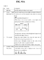
- FIG. 9 is a view which illustrates a process for controlling a lighting device, according to an exemplary embodiment
- FIGS. 10A and 10B are views schematizing the process for controlling the light device of FIG. 9 ;
- FIG. 11 is a flowchart which illustrates a driving method of a control device, according to a first exemplary embodiment
- FIG. 12 is a flowchart which illustrates a driving method of a control device, according to a second exemplary embodiment
- FIG. 13 is a view which illustrates a driving screen of a light control implemented in the user terminal of FIG. 1 ;
- FIG. 14 is a view which illustrates a portrait view of a group list
- FIG. 15 is a view which illustrates a landscape view of a group list
- FIG. 16 is a view which illustrates a detailed page view of a list
- FIG. 17 is a view which illustrates a quick panel screen
- FIGS. 18 to 29L are views schematizing a driving screen of a light control
- FIG. 30 is a view which illustrates a UI configuration, according to an exemplary embodiment
- FIGS. 31 to 41 are views which schematically illustrate regulations of a UI, according to an exemplary embodiment
- FIGS. 42 to 90 are views which illustrate a UI driving screen, according to an exemplary embodiment
- FIGS. 91A and 91B show a table that summarizes the detailed functions related to FIG. 13 ;
- FIGS. 92A and 92B show a table that summarizes the detailed functions related to FIG. 14 ;
- FIGS. 93A and 93B show a table that summarizes the detailed functions related to FIG. 15 ;
- FIGS. 94A and 94B show a table that summarizes the detailed functions related to FIG. 16 ;
- FIG. 95 shows a table that summarizes the detailed functions related to FIG. 17 .
- FIGS. 96 to 98 show tables that summarize notation regulations of the UI.
- FIG. 1 is a view which illustrates a control system of a controlled device (hereinafter, referred to as a control system) according to an exemplary embodiment
- FIGS. 2A, 2B, 2C, 2D, 3, and 4 are views which illustrate various examples to which the control system of FIG. 1 applies
- FIGS. 5 and 6 are views which illustrate an operation of controlling a light by using a user terminal of FIG. 1 .
- the control system 90 includes a part or all of a user terminal 100 , a communication network 110 , a control device 120 , and a plurality of controlled devices 130 .
- the term “including a part or all” herein means that some elements, such as a sensor 130 a , may be omitted, and/or that some elements, such as the control device 120 , are not limited to hardware and software forms, and may be integrated into another element, such as the user terminal 100 or a controlled device 130 .
- the user terminal 100 can perform the function of the control device 120
- the user terminal 100 may directly control the plurality of controlled devices 130 .
- the control system 90 of FIG. 1 illustrates all of the elements.
- the controlled device 130 refers to any type of device which can be controlled by the control device 120 .
- the controlled device 130 may include any one or more of various kinds of devices which relate to an environment where the control system 90 is installed or a characteristic of the control system 90 .
- the controlled device 130 may include any one or more of various types of devices which are usable in that environment, such as various lighting devices, an air conditioning and heating system, home appliances, and/or a blind.
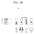
- the control system 90 includes not only a lighting system, but also a system 90 A which controls various electronic devices simultaneously by automatically calculating a ratio (or a magnification factor) as shown in FIG. 2A , a sound control system 90 B as shown in FIG. 2B , a system 90 C which controls an overall temperature in a house as shown in FIG. 2C , and a blind control system 90 D as shown in FIG. 2D .
- These systems collectively (or en bloc) control the controlled devices, such as electronic devices or sound devices, which are grouped, based on a ratio which relates to an adjustment value adjusted by a user.
- the setting values are adjusted based on a ratio which is determined based on an adjusted value. For example, in response to the user turning down the volume for a corresponding group in a state in which a target volume is set for each sound device, the target volumes of the sound devices are adjusted based on a ratio which relates to the turned-down volume.
- a target temperature is set for each space in a house as shown in FIG.
- the target temperature is adjusted by a collective control.
- a target condition such as a height of a blind
- the height may be adjusted or a blocking direction of the blind for blocking light may be changed based on a collectively controlled ratio.
- the user terminal 100 or control device 120 may provide different ratio values to the air conditioning devices 200 A, 210 A, 220 A, and 230 A in order to rapidly implement the setting designated by the user. Accordingly, the ratio for controlling several devices simultaneously can be automatically calculated in any case.
- the control system 90 B shown in FIG. 2B in response to the user collectively controlling the sounds of the plurality of sound devices 200 B, 210 B, 220 B, 230 B via the user terminal 100 or control device 120 of FIG. 1 in order to do different things while the plurality of sound devices 200 B, 210 B, 220 B, 230 B installed in the house as the plurality of controlled devices 130 of FIG. 1 are operated, the user terminal 100 or the control device 120 provides different volume levels to each of the sound devices 200 B, 210 B, 220 B, and 230 B such that the sound devices 200 B, 210 B, 220 B, and 230 B are ratio-controlled based on the transmitted volume levels.
- the ratio-controlling refers to re-adjusting (or re-setting) a predetermined value of each sound device 200 B, 210 B, 220 B, and 230 B by considering a ratio which relates to a collectively adjusted adjustment value.
- the air conditioning or heating devices installed in each room may be controlled with reference to a pre-set temperature by reflecting a relative value, that is, a different respective adjustment value, based on the collectively adjusted ratio.
- a temperature of a living room may be increased by 1° C. and a temperature of a main room may be increased by 3° C. based on a respective pre-set value for each room.
- the control method of the control system 90 of the blind device shown in FIG. 2D is not significantly different from those described above.
- the blind devices 200 D, 210 D, 220 D are ratio-controlled with reference to a respective blind height which has been set by considering an amount of light entering a corresponding window with time, such that the blind devices are pulled down based on different respective adjustment values. The same method applies when the blind devices are pulled up.
- the control system 90 may adjust each individually set setting value by additionally considering surroundings, i.e., a respective environmental quality, of each of the controlled devices in changing the setting value according to the ratio.
- the control system 90 may increase a volume adjusting ratio of a sound device of a space where the user is located in comparison with other devices by considering the presence/absence of the user as shown in top view (a) of FIG. 3 , or may adjust the volume variably based on the collectively adjusted ratio by considering a viewing mode, that is, considering whether the mode is a television (TV) viewing mode or a movie viewing mode as shown in bottom view (b) of FIG. 3 .
- the collectively adjusted ratio may be variably reflected by considering the location of the user.
- the sound devices 200 B, 210 B, 220 B, and 230 B are controlled based on the ratio which relates to the collected adjusted adjustment values.
- the sound device 200 B of the living room where the user is located is controlled by reflecting a value which is higher than the adjustment value of the ratio.
- the control system 90 B of FIG. 2B may ratio-control based on a result of detecting surroundings and/or a respective environmental quality, such as, for example, a presence and/or absence of the user.
- the sound devices 200 B, 210 B, 220 B, and 230 B of FIG. 2B may operate at different ratios based on a type of content executed in the user terminal 100 of FIG. 1 or a representative sound device of the plurality of sound devices 200 B to 230 B. Accordingly, a dynamic operation as shown in bottom view (b) of FIG. 3 can be performed.
- the sound device 230 B such as a TV, may operate according to a relatively high volume adjusting ratio in comparison with the other sound devices 200 B and 220 B.
- control systems 90 A and 90 C shown in FIGS. 2A and 2C may control the air conditioning or heating devices installed in the house based on any one or more of various variables such as surroundings, a location of the user, an area of a corresponding space, a location of the air conditioning or heating device, an external temperature, an amount of used energy, and/or any other suitable variable, as shown in FIG. 4 .
- dynamic grouping and ratio control can be performed based on a purpose of use of the user, and the temperature can be adjusted to reach a target temperature of the user.
- each air conditioning device 400 , 410 , and 420 may operate with a different air volume as shown in FIG. 4 .
- the air volume of the air conditioning device 400 of the large living room may be set to a higher value than those of the air conditioning devices 410 and 420 of the other small rooms.
- control system 90 of FIG. 1 may be modified in various forms and exemplary embodiments are not limited to the above-described exemplary embodiments.
- exemplary embodiments are not limited to the above-described exemplary embodiments.
- a lighting system will be described by way of an example for the convenience of explanation.
- the user terminal 100 includes a mobile phone such as a smartphone, a tablet personal computer (PC), a laptop computer, a desktop PC, a Personal Digital Assistant (PDA), and/or any other suitable device which performs wired and/or wireless communication.
- the user terminal 100 accesses the communication network 110 and communicates with the control device 120 .
- the user terminal 100 may communicate with the control device 120 via an access point 111 in the communication network 110 .
- the user terminal 100 may directly control the plurality of controlled devices 130 .
- the user terminal 100 collectively controls the plurality of controlled devices 130 as a group (or unit group) via an interface with the user.
- the user terminal 100 may execute an application (or a program) stored therein.
- the user terminal 100 may display a UI window on the screen by executing the application as shown in views (a), (b), and (c) of FIG. 5 .
- the UI window includes an individual control object 510 which is usable for controlling each of the lighting devices individually, and a collective control object 520 which is usable for controlling the plurality of lighting devices as a group.
- the user may group certain lighting devices (e.g., LED 1, LED 2, and LED 3) and individually set a target dimming value for each lighting device via the UI window, as shown in view (a) of FIG. 5 .
- the collective control object 520 shown in view (b) of FIG. 5 indicates an average of the individually set target dimming values.
- the user terminal 100 changes the individually set setting values of the lighting devices by reflecting a ratio which relates to the adjustment value, as shown in view (c) of FIG. 5 .
- the user individually sets the lighting devices to have respective dimming values of 50, 30, and 100 lux by adjusting the individual control object 510 of the UI window as shown in view (a) of FIG. 5 .
- the collective control object 520 of the UI window displays “60” lux which is calculated as an average of the individually set dimming values, as shown in view (b) of FIG. 5 .
- the light devices indicate 25, 15, and 50 lux, respectively.
- each of the lighting devices reduces its respective individually set dimming value by 50% by reflecting the ratio of the adjustment value adjusted by the collective control object 520 .
- View (a) of FIG. 6 illustrates an example in which a locking function is set for a lighting device designated by the user by using the collective control object.
- the lighting device for which the locking function is set does not operate in response to a manipulation or an adjustment of the collective control object.
- a locking object 630 may be displayed on an individual control object 610 which corresponds to the locking device for which the locking function is set, and only the other individual control objects 610 are controlled by reflecting the ratio of the collectively controlled adjustment value.
- each of the individual control objects 610 is controlled based on the absolute value of the adjustment value of the collective control object 620 .
- each of the individual control objects 610 is adjusted to the corresponding maximum.
- the individual control objects 610 are reset to their respective original statuses.
- a memory object 650 may be displayed on the screen.
- the user terminal 100 may continue to perform the ratio control according to an exemplary embodiment.
- the above-described method may apply in the same way when each of the individual control objects 610 is adjusted to the respective minimum.
- the user terminal 100 may limit the adjustable maximum value based on a respective environmental quality of each of the lighting devices, as shown in view (d) of FIG. 6 . For example, in response to an amount of light which enters from the outside exceeding a threshold value, the lighting device placed closest to the window does not exceed the maximum value, even if the lighting device belongs to the group which is operated by the collective control.
- the user terminal 100 receives information which relates to the plurality of controlled devices 130 registered at the control device 120 , for example, the lighting devices, via an initial loading operation. Accordingly, the user terminal 100 shares the information which relates to the plurality of controlled devices 130 with the control device 120 , so that the user can grasp the plurality of controlled devices 130 which are installed in a certain space at a glance, via the user terminal 100 .
- the user terminal 100 may provide group information which is set by the user regarding the plurality of controlled devices 130 and respective setting values of the individual controlled devices 130 - 1 to 130 -N to the control device 120 , in order to share the information with the control device 120 .
- the control device 120 may control the plurality of controlled devices 130 by reflecting the additional information.
- the user terminal 100 may provide the adjustment value in the form of a ratio value rather than an absolute value. For example, when the adjustment value indicates an increasing value by 20 lux, the increasing value information is provided not with information which is based on the value 20 but instead with a ratio value which is based on the 20 lux value.
- the user terminal 100 adjusts the individual control object 510 and the collective control object 520 by performing a dragging operation on the UI window which is displayed on the screen for the convenience of manipulation, as shown in views (a), (b), and (c) of FIG. 5 .
- the controlling operation is not limited to the dragging operation.
- the adjustment value may be changed by manipulating a button which is provided adjacent to the collective control object 520 .
- the adjustment value may be changed by a voice control and/or by a motion control.
- the user terminal 100 may analyze a voice which is collected via a microphone in order to change the adjustment value, and/or may analyze an image which is received via a camera in order to change the adjustment value.
- a direction and a range of the adjustment value may be determined by using a hand motion and a motion speed.
- the communication network 110 of FIG. 1 includes all of the wired and wireless communication networks.
- the wired network includes Internet, such as a cable network or a Public Switched Telephone Network (PSTN), and the wireless communication network includes Code Division Multiple Access (CDMA), Wideband (W)-CDMA, Global System for Mobile communications (GSM), Evolved Packet Core (EPC), Long Term Evolution (LTE), and Wibro networks.
- CDMA Code Division Multiple Access
- W Wideband
- GSM Global System for Mobile communications
- EPC Evolved Packet Core
- LTE Long Term Evolution
- the user terminal 100 may access an exchange office of a telephone office, and, when the communication network 110 is a wireless communication network, the user terminal 100 may access a Serving GRPS Support Node (SGSN) and/or a Gateway GRPS Support Node (GGSN) which is operated by a mobile network operator and may process data, or may access any one or more of various relay bases, such as Base Station Transmission (BTS), NodeB, e-NodeB, and/or any other suitable type of relay base, and may process data.
- BTS Base Station Transmission
- NodeB NodeB
- e-NodeB e-NodeB
- the communication network 110 may serve to transmit data which is processed by the user terminal 100 for collectively controlling the plurality of controlled devices 130 to the control device 120 .
- the communication network 110 includes a small base station, such as a femtocell or picocell base station, which is mainly installed in buildings, that is, the access point 111 .
- the femtocell and picocell base stations are distinguished from each other based on the corresponding maximum number of the user terminals 100 that the base station can access.
- the access point 111 includes a short-range communication module to communicate within a short range, such as Zigbee and/or Wi-Fi.
- the short-range communication may be performed according to any one or more of various standards, such as Bluetooth, Zigbee, Infrared Data Association (IrDA), Radio Frequency (RF) such as Ultra High Frequency (UHF) and Very High Frequency (VHF), Ultra Wideband (UWB), and/or any other suitable standard, in addition to Wi-Fi.
- the access point 111 extracts a location of a data packet, designates a best communication path to the extracted location, and transmits the data packet which was received from the control device 120 to the user terminal 100 via the designated communication path.
- the access point 111 is connected with the control device 120 in a wired manner in FIG. 1 , the access point 111 may be connected with the control device 120 wirelessly.
- the access point 111 may transmit the data processed by the user terminal 100 to the control device 120 .
- the access point 111 may transmit data provided by the control device 120 to the user terminal 100 .
- the user terminal 100 and the control device 120 may perform a loading operation via the access point 111 . Accordingly, the user terminal 100 and the control device 120 may share the information which relates to the plurality of controlled devices 130 .
- the control device 120 controls the plurality of controlled devices 130 based on a command of the user terminal 100 .
- the control device 120 interworks with a database (DB) 120 a .
- the DB 120 a stores a variety of information which is useful and/or necessary for controlling the plurality of controlled devices 130 .
- the control device 120 may store the variety of information, such as device IDs and location information relating to the plurality of controlled devices 130 which are installed in a certain space.
- control device 120 may acquire device IDs by communicating with the plurality of controlled devices 130 using Near Field Communication (NFC), and, in response to the individual controlled devices 130 _ 1 to 130 _N of the acquired device IDs being normally installed, the control device 120 may register the individual controlled devices 130 _ 1 to 130 _N at the DB 120 a .
- the registering process may be used more advantageously to distinguish control areas when the control device 120 is used as a communication device. For example, this is because the user should not control lighting devices in a neighboring house in the same apartment complex.
- the registered individual controlled devices 130 _ 1 to 130 _N may be deleted via the user terminal 100 or by using NFC.
- the registered device may be deleted.
- the DB 120 a may store the group information which is set for the plurality of controlled devices 130 by the user via the user terminal 100 , and may store information which relates to respective individual setting values of the individual controlled devices 130 _ 1 to 130 _N and an average of the individual setting values in the group.
- the control device 120 may calculate a ratio by using the received adjustment value.
- the calculating process may be omitted.
- the control device 120 adjusts the setting values of the plurality of controlled devices 130 belonging to the corresponding group based on the calculated ratio value, and then stores corresponding information in the DB 120 a .
- the control device 120 controls the plurality of controlled devices 130 belonging to the same group based on the adjusted setting values.
- the control device 120 may generate a control signal for adjusting dimming values of the lighting devices, and may provide the control signal to the plurality of controlled devices 130 .
- the control signal may be a switching signal for adjusting a level of a voltage applied to the plurality of controlled devices 130 , or may be a Pulse Width Modulation (PWM) signal for adjusting a time during which a current is applied.
- PWM Pulse Width Modulation
- control device 120 may adjust the setting values of the plurality of controlled devices 130 by reflecting any one or more of various functions which are set via the user terminal 100 by using the collective control. For example, in response to a lock being set for a specific controlled device 130 _ 1 ⁇ 130 _N, the control device 120 may not change the setting value of the controlled device 130 _ 1 ⁇ 130 _N for which the lock is set, and may instead maintain a previous status. In addition, when the control is set to be performed based on an absolute value rather than a ratio value, the control device 120 may calculate an absolute value of the received adjustment value, and then may adjust each of the setting values of the plurality of controlled devices 130 based on the calculated absolute value. This has been described above with reference to FIG. 6 and thus a redundant explanation is omitted.
- the control device 120 may automatically determine whether the control method is a ratio control method or a control method which is based on using an absolute value, and may operate in the control method using the absolute value according to a result of the determining. For example, in response to the adjustment value being received from the user terminal 100 , the control device 120 determines whether each of the setting values of the plurality of controlled devices 130 individually set by the user has a same value. In response to the setting values being the same value, the control device 120 adjusts the setting values of the plurality of controlled devices 130 by the absolute value. For example, referring to view (b) of FIG. 6 , the control device 120 may selectively use a manual method in which the user sets a value or an automatic method described above in order to control the plurality of controlled devices 130 by using the absolute value.
- control device 120 may adjust the setting values by reflecting a result of sensing performed by the sensor 130 a which interworks with the individual controlled devices 130 _ 1 to 130 _N.
- the sensor 130 a may sense the presence/absence of the user as shown in FIGS. 3 and 4 , or may sense an amount of light which enters through a window as shown in FIG. 6 .
- the control device 120 may adjust the setting values based on a result of the sensing performed by the sensor 130 a . For example, as shown in FIG. 6 , when the maximum dimming value is set for a lighting device which is located where a relatively large amount of light enters, the control device 120 controls the setting value of the lighting device not to exceed the maximum dimming value.
- the control device 120 may be included in a communication device of the communication network 110 .
- the control device 120 may be included in the communication network 110 in the form of a bridge, a hub, a router, and/or a repeater which can share several lines in a general network environment, rather than in the form of an individual device which is separated from the communication network 110 as shown in FIG. 1 .
- the hub differs from the wireless router in that the hub is a physical layer device for distributing only several ports, and the bridge is the same as the repeater in that the bridge connects two LANs as a data link layer device, but is different from the repeater in its capability of adjusting an amount of traffic.
- the repeater serves to amplify a weak signal.
- the bridge may re-generate data similarly as the repeater, but is different from the repeater in that the bridge re-generates the data in different locations.
- the bridge may be a combination of the repeater and the hub.
- the router connects different network layers.
- the router operates as an Internet Protocol (IP) node and sets a path with reference to routing data according to the IP. Accordingly, when the hub and the repeater are first layer devices, the bridge is a second layer device and the router is a third layer device. These communication devices may be improved to perform the operation of the control device 120 according to an exemplary embodiment.
- IP Internet Protocol
- the plurality of controlled devices 130 may include any one or more of lighting devices, sound devices, blind devices, and temperature control devices.
- the lighting device may include a light-emitting diode (LED).
- the LED is able to control dimming, that is, brightness, and thus requires a current source or a power source to control the same.
- the LED may be driven by constant voltage or constant current.
- each lighting device may include a separate driver to be driven by the constant voltage or the constant current.
- the driver may operate according to a control signal provided by the control device 120 .
- the brightness of the lighting device may be adjusted by adjusting a level of voltage applied to the LED under the control of the control device 120 .
- the brightness is increased by increasing an amount of current by adjusting a driving time during which the LED operates, that is, a pulse width.
- the plurality of controlled devices 130 may be controlled by the control device 120 in any one or more of various ways, such as by controlling the constant voltage or constant current.
- the individual controlled devices 130 _ 1 to 130 _N may operate according to a result of the sensing performed by the sensor 130 a .
- the sensor 130 a may be provided for each of the plurality of individually controlled devices 130 _ 1 to 130 _N.
- the sensor 130 a may include any one or more of various types of sensors which are configured to detect surroundings and/or environmental qualities of the individual controlled devices 130 _ 1 to 130 _N.
- the sensor is related to the ratio control operation.
- the sensor 130 a may include an infrared ray operation sensor configured to determine the presence/absence of the user, or may include a light sensor configured to determine an amount of light which enters from the outside.
- the sensor 130 a may provide information which relates to the amount of light entering from the outside to the control device 120 , and the control device 120 may operate the lighting devices in any one or more of various ways according to a result of the sensing provided from the sensor 130 a .
- the control device 120 may turn off the corresponding lighting device in response to the amount of light exceeding the threshold value as a result of the sensing of the sensor 130 a .
- the control device 120 controls only the other lighting devices of the same group by adjusting the setting values based on the ratio value.
- control device 120 may adjust the setting value only up to the maximum value of the corresponding lighting device, regardless of the ratio value.
- the user terminal 100 interworks with the control device 120 via the communication network 110 in order to control the plurality of controlled devices 130 .
- the user terminal 100 when the user terminal 100 includes a hardware element such as a memory or a software element of the control device 120 and performs the operation of the control device 120 , the user terminal 100 can directly control the plurality of controlled devices in any case.
- the control device 120 when the control device 120 is integrated into the plurality of controlled devices 130 , the user terminal 100 may directly control the plurality of controlled devices 130 .
- FIGS. 7A and 7B are block diagrams which illustrate a configuration of the user terminal of FIG. 1 .
- the user terminal 100 is configured to interwork with the control device 120 of FIG. 1 , for example, and includes a part or all of a communication interface 700 , a controller 710 , a user interface 720 , a storage 730 , and a group control executer 740 .
- the term “including a part or all” herein may mean that some elements, such as the storage 730 , may be omitted and/or that some elements, such as the group control executer 740 , may be integrated into the controller 710 as shown in FIG. 7B .
- the user terminal 100 includes all of the elements.
- the communication interface 700 communicates with the control device 120 .
- the communication interface 700 may communicate with each individual device of the plurality of controlled devices 130 .
- the communication interface 700 may communicate with each one of the plurality of controlled devices 130 .
- the controller 710 performs an overall operation to control the communication interface 700 , the user interface 720 , the storage 730 , and the group control executer 740 of the user terminal 100 .
- the controller 710 may operate the group control executer 740 based on the user command.
- the controller 710 may control the communication interface 700 to provide information which relates to the adjustment value to the control device 120 .
- the controller 710 may provide group information stored in the storage 730 and additional information relating to whether the adjustment value is an increasing value or decreasing value, in conjunction with the adjustment value. Furthermore, the controller 710 may control the communication interface 700 to provide information which relates to any one or more of various functions set by the user via the user interface 720 to the control device 120 . When a lock is set or a control method using an absolute value rather than a ratio value is set, the controller 710 may control the communication interface 700 to provide corresponding setting information to the control device 120 .
- the user interface 720 may include a display and a button inputter.
- a user command may be received by means of a user's touch.
- the button inputter may be omitted.
- data generated by driving of the group control executer 740 may be displayed on the screen and the user command may be provided via the button inputter.
- the button inputter may include any one or more of various buttons, such as a direction button and/or a number button.
- the storage 730 stores a variety of information which is processed in the user terminal 100 .
- the storage 730 may share information relating to the plurality of controlled devices 130 by communicating with the control device 120 , and may store the shared information.
- the user terminal 100 may store basic information, such as group information which is usable for collectively controlling the plurality of controlled devices 130 in a specific group.
- the group control executer 740 may store an application for collectively controlling the plurality of controlled devices via the control device 120 of FIG. 1 , and may execute the application stored under the control of the controller 710 based on a user's request.
- the user interface 720 may display the UI screen on the screen as shown in views (a), (b), and (c) of FIG. 5 .
- the UI will be explained in detail below.
- the group control executer 740 may generate an adjustment value in order to provide an adjustment value to be collectively adjusted by the user to the control device 120 , or may generate a ratio value in order to provide a ratio value for the adjustment value to the control device 120 .
- the adjustment value or ratio value generated in this way may be transmitted to the communication interface 700 under the control of the controller 710 .
- the user terminal 100 may include any one or more of various function blocks.
- the user terminal 100 may include a microphone and a camera, and may include an analysis module for analyzing information acquired by the microphone and the camera.
- the plurality of controlled devices 130 can be grouped and the plurality of controlled devices 130 in the group can be collectively controlled. Therefore, the present disclosure is not limited to the above-described exemplary embodiments.
- FIGS. 8A and 8B are block diagrams which illustrate a configuration of the control device of FIG. 1 .
- the control device 120 is configured to interwork with the user terminal 100 of FIG. 1 , and includes a part or all of a communication interface 800 , a controller 810 , a storage 820 , and a setting value adjuster 830 .
- control device 120 includes all of the elements.
- the communication interface 800 communicates with the user terminal 100 and the plurality of controlled devices 130 .
- the communication interface 800 may receive an adjustment value which is adjustable by the user in order to collectively control the plurality of controlled devices 130 , and may also receive a variety of additional information corresponding to the adjustment value by communicating with the user terminal 100 .
- the communication interface 800 may receive information relating to any one or more of various setting functions set by the user on the user terminal 100 .
- the communication interface 800 may receive a result of sensing performed by the sensor 130 a of FIG. 1 via the plurality of controlled devices 130 .
- the communication interface 800 may register the individual controlled devices 130 _ 1 to 130 _N by using NFC.
- the controller 810 registers each of the individual controlled devices 130 _ 1 to 130 _N at the storage 820 or the separate DB 120 a , and then, in response to respective signals being received from the individual controlled devices 130 _ 1 to 130 _N, the controller 810 may determine that the individual controlled devices 130 _ 1 to 130 _N are installed. In this case, the controller 810 may use respective device IDs of the individual controlled devices 130 _ 1 to 130 _N.
- the controller 810 may control an overall operation of the communication interface 800 , the storage 820 , and the setting value adjuster 830 of the control device 120 . For example, in response to an adjustment value being received from the user terminal 100 via the communication interface 800 , the controller 810 may transmit the adjustment value to the setting value adjuster 830 . Of course, in response to the adjustment value being provided in the form of a ratio value, the controller 810 may transmit the adjustment value to the setting value adjuster 830 . In response to a request of the setting value adjuster 830 , the controller 810 may provide setting value information which relates to each of the individual controlled devices 130 _ 1 to 130 _N of FIG. 1 belonging to the same group, which is stored in the storage 820 or the separate DB 120 a . Thereafter, the controller 810 may store setting value information which is adjusted by the setting value adjuster 830 in the storage 820 and/or in the DB 120 a.
- the controller 810 controls the plurality of controlled devices 130 based on the setting values adjusted by the setting value adjuster 830 .
- the controller 810 may generate control signals for controlling the plurality of controlled devices 130 and may provide the control signals to the plurality of controlled devices 130 .
- the controller 810 may generate a control signal for reducing a level of applied voltage and may provide the control signal.
- various levels of voltages may be applied to the individual controlled devices 130 _ 1 to 130 _N.
- the controller 810 may provide a switching signal as the control signal in order to select a specific level of voltage.
- the storage 820 may temporarily store the information which is processed in the control device 120 .
- the control device 120 may store information which is necessary for collectively controlling the plurality of controlled devices of FIG. 1 in the DB 120 a which interworks with the control device 120 .
- the control device 120 may store the information which needs to be temporarily stored for rapid information processing in the storage 820 , and may use the information afterward.
- the setting value adjuster 830 adjusts (or calculates) the respective setting values of the individual controlled devices 130 _ 1 to 130 _N, which are pre-set by the user.
- the setting value adjuster 830 may calculate a ratio value by using the adjustment value.
- the setting value adjuster 830 may use information which relates to an average of a specific group.
- the setting value adjuster 830 may calculate a ratio of the adjustment value to the average, and, when the adjustment value is an increasing value, the setting value adjuster 830 may calculate a ratio of the adjustment value to a value which is obtainable by subtracting the average from the maximum adjustable value.
- the setting value adjuster 830 adjusts each of the respective setting values of the individual controlled devices 130 _ 1 to 130 _N according to the calculated ratio. In response to the ratio value being directly received from the user terminal 100 , the setting value adjuster 830 adjusts only the pre-set setting values of each of the individual controlled devices 130 _ 1 to 130 _N. In this case, the setting value adjuster 830 may reflect a variety of setting information provided by the controller 810 in adjusting the setting values. For example, in response to a lock being set, the setting value adjuster 810 may not adjust the setting value of the individual controlled device 130 _ 1 ⁇ 130 _N for which the lock is set. The setting values adjusted by the setting value adjuster 830 may be provided to the controller 810 .
- FIG. 9 is a view which illustrates a collective control process of a lighting device, according to an exemplary embodiment
- FIGS. 10A and 10B are diagrams which illustrate the collective control process of the lighting device of FIG. 9 .
- the user terminal 100 provides a group dimming adjustment value, that is, an adjusted dimming value, to the control device 120 .
- the user terminal 100 may display a UI window on the screen based on a user's request.
- the UI displays an individual control object 1110 and a group control object 1120 , as shown in FIGS. 10A and 10B .
- the individual control object 1110 indicates pre-set setting values of lighting devices 130 ′- 1 , 130 ′- 2 , and 130 ′- 3 of FIG. 9
- the group control object 1120 indicates an average of the pre-set setting values. Therefore, the adjusted dimming value is a value which is obtained by adjusting the average.
- the control device 120 calculates individual dimming adjustment values of each of the lighting devices 130 ′- 1 , 130 ′- 2 , and 130 ′- 3 by using the received dimming adjustment value. More specifically, the control device 120 calculates a ratio which relates to the received dimming adjustment value and adjusts each of the pre-set dimming values individually by reflecting the calculated ratio value.
- the control device 120 provides the dimming values which are adjusted according to the ratio to each of the lighting devices 130 ′- 1 , 130 ′- 2 , and 130 ′- 3 . More specifically, the control device 120 may provide control signals indicating the adjusted dimming values. However, when the lighting devices 130 ′- 1 , 130 ′- 2 , and 130 ′- 3 include their respective controllers, the control device 120 may transmit information relating to the adjusted dimming values to each of the lighting devices 130 ′- 1 , 130 ′- 2 , and 130 ′- 3 , and each of the lighting devices 130 ′- 1 , 130 ′- 2 , and 130 ′- 3 may adjust a respective brightness by using the information on the adjusted dimming values.
- the lighting devices 130 ′- 1 , 130 ′- 2 , and 130 ′- 3 may inform the control device 120 that the adjusted dimming values are normally received.
- control device 1120 updates the DB 120 a interworking therewith with new information relating to the adjusted dimming values in operation S 940 , and may inform the user terminal 100 of the new information relating to the adjusted dimming values in operation S 950 .
- the user terminal 100 may request information which relates to attributes and statuses of the lighting devices 130 ′- 1 , 130 ′- 2 , and 130 ′- 3 by communicating with the control device 120 , and in operation S 970 , the control device 120 may provide the information in response to the request.
- the user terminal 100 may display the UI window which includes the individual control objects 1110 and the group control object 1120 on the screen as shown in FIG. 10A .
- the control device 120 controls each of the lighting devices 130 ′- 1 , 130 ′- 2 , and 130 ′- 3 to have the maximum dimming value, regardless of the ratio control. Accordingly, all of the individual control objects 1110 and the group control object 1120 on the screen of the user terminal 100 indicate the maximum value.
- the control device 120 returns to the previous status. To achieve this, the control device 120 may refer to the previous setting value information stored in the DB 120 a.
- the user may increase the dimming value by 25 out of the adjustable remaining dimming value of 50 by adjusting the group control object 1120 as shown in FIG. 10B .
- the dimming value increases by 50% of the value which is obtained by subtracting the average from the maximum value. Therefore, the control device 120 controls each of the individual lighting devices 130 ′- 1 , 130 ′- 2 , and 130 ′- 3 at the ratio of 1 ⁇ 2 and thus increases the pre-set dimming values by 50%.
- the individual control objects 1110 indicating the dimming values of 70, 50, and 30 on the UI of the user terminal 100 are changed to indicate the dimming values of 85, 75, and 65.
- FIG. 11 is a flowchart which illustrates a driving method of a control device, according to a first exemplary embodiment.
- the control device 120 receives an adjustment value for collectively controlling the plurality of controlled devices 130 in the group from the user terminal 100 .
- the adjustment value may be provided in the form of an absolute value or a ratio value.
- the control device 120 may receive information relating to whether the adjustment value is an increasing value or decreasing value at the same time of receiving the adjustment value.
- control device 120 adjusts pre-set values of the plurality of controlled devices according to a ratio which relates to the received adjustment value. This has been described above with reference to FIG. 10B and a redundant explanation is omitted.
- the control device 120 controls the plurality of controlled devices 130 based on the adjusted setting values (S 1120 ).
- the control device 120 may control each of the plurality of controlled devices 130 individually.
- the plurality of controlled devices 130 may include any one or more of various devices such as sound devices, blind devices, etc. in addition to the above-mentioned lighting devices.
- FIG. 12 is a flowchart which illustrates a driving method of a control device according to a second exemplary embodiment, which includes controlling a lighting device by using an absolute value.
- the control device 120 receives a dimming value for collectively controlling the plurality of lighting devices 130 ′- 1 , 130 ′- 2 , and 130 ′- 3 from the user terminal 100 .
- the dimming value refers to an adjustment value for an average value, and may be provided in the form of an absolute value or a ratio value.
- the control device 120 determines whether the dimming values which have been pre-set for each of the plurality of lighting devices 130 ′- 1 , 130 ′- 2 , and 130 ′- 3 in the same group are the same value or not. To achieve this, the control device 120 may retrieve the pre-set dimming values of the plurality of lighting devices 130 ′- 1 , 130 ′- 2 , and 130 ′- 3 belonging to the same group from the DB 120 a which interworks with the control device 120 , and may compare the retrieved dimming values.
- the control device 120 adjusts the respective setting values of the plurality of lighting devices 130 ′- 1 , 130 ′- 2 , and 130 ′- 3 based on to a ratio which relates to the received dimming value.
- the adjusting herein may include calculating a ratio and determining an adjustment range according to the calculated ratio.
- the control device 120 adjusts the setting values of each of the plurality of lighting devices 130 ′- 1 , 130 ′- 2 , and 130 ′- 3 by an absolute value of the adjusted dimming value.
- the adjusting herein may include calculating the absolute value.
- the adjusted setting values are collectively transmitted to the plurality of lighting devices 130 ′- 1 , 130 ′- 2 , and 130 ′- 3 .
- the control device 120 may individually or collectively control the plurality of lighting devices 130 ′- 1 , 130 ′- 2 , and 130 ′- 3 according to the adjusted setting values, based on the ratio control or the absolute value control.
- FIGS. 13, 14, 15, 16, and 17 are views which illustrate a driving screen of a light control implemented in the user terminal of FIG. 1 .
- the user terminal 100 displays a list of LEDs as shown in views (a), (b), and (c) of FIG. 13 .
- the displayed list provides information relating to installed individual LEDs. It is possible to control the LEDs one by one by using the list.
- View (a) of FIG. 13 illustrates a quick view of the individual LEDs
- view (b) of FIG. 13 illustrates a detail view of the individual LEDs.
- View (c) of FIG. 13 illustrates a screen which is displayed in response to LED 2 being selected in view (b) of FIG. 13 .
- view (d) of FIG. 13 shows a button to move to a setting page.
- FIG. 13 Detailed functions related to FIG. 13 may be summarized in Table 1 of FIGS. 91A and 91B .
- FIG. 14 is a view which illustrates a portrait view of the group list.
- the group list provides LED information relating to each group, and it is possible to control the lights on a group basis or an LED basis by using the group list.
- View (a) of FIG. 14 illustrates a quick view of the groups of the LEDs
- view (b) of FIG. 14 illustrates a detail view of the groups of the LEDs
- view (c) of FIG. 14 shows individual LEDs included in Group 1.
- FIG. 14 Detailed functions related to FIG. 14 are shown in Table 2 of FIGS. 92A and 92B .
- FIG. 15 is a view which illustrates a landscape view of the group list.
- the group list of FIG. 15 provides LED information of each group, and it is possible to control the lights on a group basis or an LED basis by using the group list.
- the landscape view may be activated only in the group list.
- FIG. 15 Detailed functions related to FIG. 15 are explained in Table 3 of FIGS. 93A and 93B .
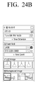
- FIG. 16 is a view which illustrates a detailed page view of the list.
- the detailed page of FIG. 16 provides detailed information relating to individual or group LEDs, and the user may set respective setting values on each piece of the detailed information. For example, the user may set a pattern for changing dimming of a light in a predetermined form with time, and may set a light to inform of a phone call when a phone call is received from a specific person of a set phone number.
- FIG. 16 Detailed functions related to FIG. 16 are shown in Table 4 of FIGS. 94A and 94B .
- FIG. 17 is a view which illustrates a quick panel screen.
- the quick panel screen displays lights which are added as favorites, for example, up to 4 lights, on a quick panel. In particular, in response to the user dragging down an upper area of the screen, the lights added as favorites may appear.
- View (b) of FIG. 17 shows a screen which displays the lights added as favorites in a landscape form.
- FIGS. 18 to 29L are diagrams which illustrate a driving screen of a light control.
- the user terminal 100 may execute an application for controlling lights and may display a loading screen as shown in FIG. 18 .
- the user terminal 100 may share information which relates to the plurality of lighting devices 130 ′- 1 , 130 ′- 2 , and 130 ′- 3 with the control device 120 .
- the user terminal 100 displays a main screen, as shown in FIG. 19A , FIG. 19B , and FIG. 19C .
- a main screen as shown in FIG. 19A , FIG. 19B , and FIG. 19C .
- FIGS. 13 and 14 Detailed descriptions regarding this have been provided above with reference to FIGS. 13 and 14 and thus a redundant explanation is omitted.
- FIGS. 20A and 20B are views which illustrate a guide pop-up screen.
- the user terminal 100 displays information relating to whether brightness is to be adjusted or a display mode is to be changed in the form of a pop-up window, and enables the user to make a selection.
- FIGS. 21A and 21B show a quick panel screen similar to that shown in FIG. 17 .
- FIG. 21A shows a portrait view
- FIG. 21B shows a landscape view.
- FIGS. 22A and 22B are views which illustrate a landscape view of individual lighting devices, and FIG. 23 illustrates a process of adjusting an icon of LED 03.
- the screen of FIG. 22A shows information indicating the current screen position on a lower portion.
- FIGS. 24A and 24B are views which illustrate a detailed setting screen similar to that shown in FIG. 16 .
- the user may set a variety of information, such as a pattern of a light, a mode of a set pattern, and schedule.
- the user may set a shape of a lampshade.
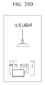
- FIGS. 25A, 25B, 25C, 25D, 25E, 25F, 25G, 25H, 25I, 25J, 25K, and 25L are views showing various kinds of lampshades.
- the user may select a lampshade that the user prefers as a representative image of a light.
- FIGS. 26A, 26B, and 26C are views which illustrate screens displayed in response to a specific item being selected in FIGS. 24A and 24B .
- the corresponding screens may be displayed in a pop-up form.
- FIG. 26C shows a screen for searching for a phone number.
- FIGS. 27A, 27B, and 27C show a screen for setting a group ( FIG. 27A ), a screen for setting individual lights ( FIG. 27B ), and a screen for adding a light ( FIG. 27C ).
- FIGS. 28A, 28B, and 28C show a screen for deleting individual LEDs ( FIG. 28A ), a screen for changing a name ( FIG. 28B ), and a screen for informing that there is no light to be deleted ( FIG. 28C ).
- FIGS. 29A, 29B, 29C, 29D, 29E, 29F, 29G, 29H, 29I, 29J, 29K, and 29L are views which show various types of pop-up windows.
- FIG. 30 is a view which illustrates a UI configuration, according to an exemplary embodiment.
- a UI may operate in two depths.
- item 1 indicates a parallel configuration like a tab configuration and indicates toggling as an [individual-group toggle button]
- item 2 indicates changing to a landscape view in response to a group list being changed to a landscape view.
- the individual LED list is not changed to the landscape view.
- item 3 indicates that each list can provide two types of views, such as a quick view and a detail view.
- FIGS. 31 to 41 are views which illustrate regulations of a UI briefly, according to an exemplary embodiment.
- Tables 6, 7, and 8 of FIGS. 96 to 98 Prior to the description of the regulations of the UI, notation regulations are summarized as shown in Tables 6, 7, and 8 of FIGS. 96 to 98 .
- Table 6 of FIG. 96 shows touch gestures
- Table 7 of FIG. 97 shows touch feedback statuses
- Table 8 of FIG. 98 shows screen definition and operation flow.
- FIG. 31 Views (a), (b), and (c) of FIG. 31 schematize FIG. 30 .
- An individual LED list screen is displayed as shown in view (a) of FIG. 31 , and then is changed to a group list screen by selecting a toggle button, as shown in view (b) of FIG. 31 .
- a group peeping screen may be displayed.
- a screen shown in view (c) of FIG. 31 may be displayed. In this case, neighboring groups may be identified by performing the horizontal flicking operation.
- Views (a) and (b) of FIG. 32 illustrate an operation of changing to a previous screen.
- a screen shown in view (b) of FIG. 32 is displayed.
- the screen shown in view (a) of FIG. 32 is restored.
- FIGS. 33, 34, 35, and 36 illustrate various screens related to a pop-up window.
- the pop-up window includes basic text information and a title area, a selectable GUI button, and an icon for distinguishing a situation may be added to the pop-up window according to a shape of the pop-up window.
- the pop-up window may use a pop-up window provided by the system, and a separate pop-up window may be added when there is no pop-up window, depending on a platform.
- a background area except for the pop-up window is inactivated.
- the pop-up window may be divided into a basic dialog pop-up window, an alert pop-up window, a list pop-up window, and a toast pop-up window.
- FIG. 33 Views (a), (b), (c), (d), (e), (f), and (g) of FIG. 33 illustrate the basic dialog pop-up window.
- the basic dialog pop-up window is a pop-up window for performing functions and includes a plurality of function lists, a selectable GUI button such as ‘Yes/No’, ‘OK’, etc., and an element having an interaction such as a text input area.
- item 1 provides a title of a corresponding pop-up window
- item 2 indicates an area for showing contents of the corresponding pop-up window and provides a message, a list, a text box, a seek bar, a spinner, etc. according to a kind of the pop-up window
- item 3 provides OK and Cancel. Depending on times, only OK may be provided.
- Views (a) and (b) of FIG. 34 show an alert pop-up window.
- the alert pop-up window may be divided into two types based on a seriousness of a message. Most messages do not require a title, but a high danger work or a work including a potential data loss may use a dialog having a title.
- item 1 indicates an area for showing contents of a corresponding pop-up window and provides a message, a list, a text box, a seek bar, a spinner, and any other suitable type of field, according to a kind of the pop-up window
- item 3 provides OK and Cancel. Depending on times, only OK may be provided. Item 3 indicates that a highly important pop-up window which should be notified to the user may use an icon.
- Views (a) and (b) of FIG. 35 show a list pop-up window.
- the list pop-up window is used when the user is allowed to select only one. Accordingly, a button is not provided.
- the pop-up window is terminated.
- item 1 provides a title of a corresponding pop-up window
- item 2 is an area for showing contents of the corresponding pop-up window.
- FIG. 36 Views (a), (b), (c), and (d) of FIG. 36 show a toast pop-up window.
- the toast pop-up window is used when simple feedback is provided in the form of a small toast pop-up window.
- a toast notice is a message which is provided in the form of a pop-up window on a surface of a window. The toast fills a space required by a message, and a user's current action is interactive and is provided as if it can be seen. The notice may automatically appear and disappear and an interaction in the pop-up window is not allowed.
- FIG. 37 illustrates a screen which shows a menu button as a UI element. As shown in views (a) and (b) of FIG. 37 , a function which can be performed in a corresponding page may be provided as a menu button.
- FIG. 38 illustrates a screen showing a scroll as a UI element.
- the scroll indicates the whole width and height lengths of a corresponding page, and may serve as an indicator.
- FIGS. 39 and 40 illustrate screens which show a text input as a UI element.
- An on-screen keyboard provided by the system is used, and different types of on screen keyboards may be provided according to an input type of a text, as shown in views (a), (b), and (c) of FIG. 39 .
- Views (a), (b), (c), (d), and (e) of FIG. 40 illustrate a process which is commonly applied in response to a text being input.
- View (a) of FIG. 40 shows that there is no keypad at the time of entering
- view (b) of FIG. 40 shows that a keypad appears in response to a text box being tapped
- view (c) of FIG. 40 shows that a text field is displayed in response to [Text] being input.
- reference numerals 3900 A, 3900 B, and 3900 C and reference numerals 4000 B, 4000 C, and 4000 D indicate cursors. The locations of these cursors may be set as a respective default.
- FIG. 41 illustrates a screen which shows a task completion as a UI element, and shows a process which is applied when a task such as addition, deletion, and setting change is completed.
- FIGS. 42 to 90 are views illustrating a UI driving screen, according to an exemplary embodiment.
- FIG. 42 shows a screen which is displayed when loading is performed
- FIG. 43 shows a screen which is displayed when loading fails.
- a light of a lamp becomes brighter as a loading number increases from 0 to 100%.
- a detail view may be fixed as shown in view (e) of FIG. 42 .
- the view method may succeed a view status when a previous application was closed.
- An LED view may be provided to the user who has terminated an application in the LED view status
- a group view may be provided to the user who has terminated an application in the group view status.
- FIGS. 44, 45, 46, 47, 48, and 49 illustrate LED list-related screens.
- FIG. 44 illustrates an LED list screen and shows a list unfolding screen and a list folding screen.
- FIG. 45 illustrates an LED list screen for controlling collectively turned on/off buttons and individually turned on/off buttons.
- all lights are turned on, and thus an “All Light” subtitle area is changed to “5 Lights On” as shown in view (b) of FIG. 45 .
- an “All Light” subtitle area is changed to “4 Lights On” as shown in view (b) of FIG. 45 .
- FIG. 46 shows adjusting dimming on the LED list screen.
- FIG. 47 illustrates adding and/or deleting favorites on the LED list screen.
- View (e) of FIG. 47 shows that a pop-up window registered as favorites appears in the quick panel
- view (f) of FIG. 47 shows that a light deleted from favorites is removed from the quick panel.
- FIG. 48 shows a favorites list excess notice on the LED list screen. The notice may be displayed in a pop-up window form, as shown in view (b) of FIG.
- FIG. 49 shows changing a light icon on the LED list screen.
- the icon image may be changed as shown in view (b) of FIG. 49 and view (c) of FIG. 49 .
- the icon mage is finally changed by selecting OK in view (c) of FIG. 49 .
- FIGS. 50, 51, 52, and 53 illustrate an individual light peeping screen.
- a screen shown in view (b) of FIG. 50 is displayed.
- a screen shown in view (c) of FIG. 50 is displayed.
- a newly flicked list is opened, and a previously flicked list returns to its original status.
- FIG. 51 illustrates light management.
- LEDs are displayed in addition to the already registered LEDs, as shown in view (c) of FIG. 51 .
- FIG. 52 illustrates dimming setting
- FIG. 53 illustrates a screen displayed when tapping is performed for a long time. For example, in response to an LED 1 being tapped for a long time in FIG. 53 , the LED 1 is in a movable status. Accordingly, the LED 1 may be moved or deleted.
- FIGS. 54 to 76 illustrate screens related to details setting.
- FIG. 54 is a view which illustrates an entry into a details setting screen.
- the screen may be changed to a details setting screen of the LED 1.
- Details setting screens of an individual LED and a group LED of view (c) of FIG. 54 and view (g) of FIG. 54 are different from each other in the presence/absence of an upper end title menu button (a dashed line portion).
- FIG. 55 illustrates a screen for adding a light in a group.
- a screen shown in view (c) of FIG. 55 is displayed.
- FIG. 56 illustrates a screen for deleting a light from a group.
- a list of lights in the group is provided, as shown in view (c) of FIG. 56 .
- FIG. 57 illustrates a screen for deleting all lights from a group.
- FIG. 58 illustrates a screen for changing a light/group name. In response to an overlapping group name being input or in response to a group name not being input, pop-up windows shown in views (f) and (g) of FIG. 58 may be provided.
- FIG. 59 illustrates a screen for selecting a pattern.
- FIGS. 60 and 61 illustrate screens for adding and deleting a pattern, and a guide may be provided by using an automatic drawing animation as shown in views (b) and (c) of FIG. 60 .
- FIG. 62 illustrates a screen for deleting a set pattern when an event is notified. For example, in response to a phone call being received from a specific person, a pattern set for a light may be deleted.
- FIG. 63 is a view which illustrates selecting and/or releasing a mode.
- the mode may be a sleep mode, etc., as shown above in Table 4 of FIGS. 94A and 94B .
- FIG. 64 illustrates selecting and/or releasing a schedule
- FIG. 65 illustrates a schedule addition screen.
- FIG. 66 is a screen illustrating a schedule editing process
- FIG. 67 illustrates a schedule deleting process.
- FIG. 68 is a screen illustrating selecting and/or releasing an event notice, and, in response to an event notice being set, an event setting icon is generated in an extension view indicator area as shown in view (d) of FIG. 68 .
- an event notice may be added by using a list of phone numbers as shown in FIG. 69 .
- an event notice may be added by directly inputting a phone number as shown in FIG. 70 .
- FIG. 71 illustrates a process for correcting the event notice.
- FIG. 72 illustrates deleting an event notice.
- FIG. 73 illustrates a process for selecting an LED image
- FIG. 74 illustrates a process for selecting a BG image
- FIG. 75 illustrates selecting and/or releasing a baby/night care.
- the baby care refers to setting a light to be automatically turned on with low brightness in response to a baby's cry being heard.
- the night care refers to a function of automatically turning on a light with set brightness in response to the user raising a user's smartphone.
- FIG. 76 In response to details setting being stored as shown in FIG. 76 , a previous screen is restored, as shown in view (b) of FIG. 76 .
- FIGS. 77 to 85 illustrate screens related to a landscape view.
- FIG. 77 shows an entry into a landscape view.
- the screen In response to the screen being rotated in a portrait view shown in views (a) and (b) of FIG. 77 , the screen enters the landscape view. In response to the screen being rotated again, the screen returns to its original status.
- FIG. 78 is a screen which illustrates moving to another room. In views (a) and (c) of FIG. 78 , a cue informing that there are different rooms on the left and right is shown.
- FIG. 79 is a screen which illustrates moving to another room. In the case of a group which has more than the maximum number of LEDs in one page, a cue informing that there is still another room on the left is displayed on a lower end as shown in view (a) of FIG.
- FIG. 80 illustrates a process for setting dimming in a landscape view. As shown in view (a) of FIG. 80 , dimming may be reduced by adjusting LED 1.
- FIG. 81 is a screen which illustrates adding and/or deleting favorites. When four favorites have been already registered, a pop-up window may be displayed as shown in view (b) of FIG. 81 .
- FIGS. 82 and 83 illustrate a light management screen and adding and/or deleting a light. As shown in view (e) of FIG. 82 , in response to a light being added, a group may be set to have an average dimming value and may be added.
- FIG. 84 illustrates a location movement of an LED in response to a long tapping operation.
- FIG. 85 is a screen for deleting an LED in response to a long tapping operation.
- the LED 1 may be deleted by being dragged to a deletion button.
- the deletion button may be visually different, or a color and/or a size may be changed, as shown in view (c) of FIG. 85 .
- other LEDs are pushed and moved as shown in view (d) of FIG. 85 .
- FIGS. 86, 87A, and 87B are setting screens and illustrate deleting and editing an LED.
- the deleting process is performed by selecting a deletion item in view (b) of FIG. 86 , and pop-up windows related to the LED deletion may be displayed during this process.
- pop-up windows related to the LED deletion may be displayed during this process.
- an already-registered place may be provided in a pop-up window form.
- [+Add New Location] is displayed on a lowermost end.
- FIGS. 88, 89, and 90 illustrate screens related to group registration and management.
- the light may be added and/or deleted by the process shown in FIGS. 88 and 89 , and the group icon may be changed as shown in FIG. 90 .
- each of the elements may be implemented as a single independent hardware component, some or all of the elements may be selectively combined and may be implemented as a computer program having a program module for performing some or all of functions combined in one or a plurality of hardware components. Codes and code segments constituting the computer program can be easily inferred by an ordinary skilled person in the art. Such a computer program may be stored in a non-transitory computer readable medium, and may be read and executed by a computer, so that the exemplary embodiments can be implemented.
- the non-transitory computer readable medium refers to a medium that stores data semi-permanently rather than storing data for a very short time, such as a register, a cache, and a memory, and is readable by an apparatus.
- the above-described programs may be stored in a non-transitory computer readable medium, such as, for example, any one or more of a compact disc (CD), a digital versatile disk (DVD), a hard disk, a Blu-ray disk, a universal serial bus (USB), a memory card, and a read only memory (ROM), and may be provided.
Landscapes
- Engineering & Computer Science (AREA)
- Theoretical Computer Science (AREA)
- General Engineering & Computer Science (AREA)
- Human Computer Interaction (AREA)
- Physics & Mathematics (AREA)
- General Physics & Mathematics (AREA)
- Computer Networks & Wireless Communication (AREA)
- Signal Processing (AREA)
- Health & Medical Sciences (AREA)
- Computing Systems (AREA)
- General Health & Medical Sciences (AREA)
- Medical Informatics (AREA)
- Multimedia (AREA)
- Circuit Arrangement For Electric Light Sources In General (AREA)
Abstract
A user terminal and a driving method thereof, a control device and a driving method thereof, and a control system of a controlled device are provided. The user terminal includes: a communication interface configured to communicate with a plurality of controlled devices which are operated based on individually set setting values; a user interface configured to receive an adjustment value for collectively controlling the plurality of controlled devices as a group; and a controller configured to individually adjust each of the setting values based on a ratio which relates to the received adjustment value, and to control the plurality of controlled devices based on the adjusted setting values.
Description
This application claims the benefit of U.S. Provisional Patent Application No. 61/837,771, filed on Jun. 21, 2013, in the United States Patent and Trademark Office, and priority from Korean Patent Application No. 10-2014-0029141, filed on Mar. 12, 2014 in the Korean Intellectual Property Office, the disclosures of which are hereby incorporated by reference in their entireties.
Apparatuses and methods consistent with exemplary embodiments relate to a user terminal and a driving method thereof, a control device and a driving method thereof, and a control system of a controlled device, which can sensately control a lighting device, a sound device, a temperature control device, and a blind device via a Graphic User Interface (GUI) displayed on a screen of the user terminal such as a smartphone.
An incandescent lamp or fluorescent lamp consumes much power for its illumination efficiency, and has a relatively short operational life. In particular, the fluorescent lamp may cause a serious environmental pollution problem due to mercury discharged when the fluorescent lamp is discarded. Therefore, an eco-friendly light emitting diode (LED) which consumes less power and has a semi-permanent life has received widespread interest. In particular, the LED has merits in that its dimming and color can be easily adjusted.
It is common that a light is only turned on or off via a remote controller or an on/off switch. However, in recent years, the light has become so developed that a status of each light can be checked, a plurality of lights can be controlled, and a light can be remotely controlled simply by using a smartphone.
However, a related-art light control method is limited to turning on or off a light and adjusting color and dimming by executing an application which is stored in a smartphone. Therefore, there is a problem that recent consumer demand for controlling the lights more sensately is not satisfied.
One or more exemplary embodiments may overcome the above disadvantages and other disadvantages not described above. However, it is understood that one or more exemplary embodiments are not required to overcome the disadvantages described above, and may not overcome any of the problems described above.
One or more exemplary embodiments provide a user terminal and a driving method thereof, a control device and a driving method thereof, and a control system of a controlled device, which can easily control a plurality of controlled devices.
According to an aspect of an exemplary embodiment, there is provided a user terminal including: a communication interface configured to communicate with each of a plurality of controlled devices which are operated based on individually set setting values; a user interface configured to receive an adjustment value for collectively controlling the plurality of controlled devices as a group; and a controller configured to individually adjust each of the setting values of the plurality of controlled devices based on a ratio which relates to the adjustment value, and to control the plurality of controlled devices based on the adjusted setting values.
The controller may be further configured to calculate an average value based on the setting values, to calculate at least one from among a ratio of the received adjustment value to the calculated average value and a ratio of the received adjustment value to a value which is obtainable by subtracting the calculated average value from a maximum setting value, and to individually adjust each of the setting values based on the calculated at least one ratio.
The user interface may be further configured to display a user interface (UI) window which displays the plurality of controlled devices as a group and displays a collective control object which is usable for collectively controlling operations of the controlled devices, and, in response to the displayed collective control object being adjusted by a user manipulation, the controller may be further configured to determine the adjustment value based on an adjustment status of the collective control object.
The UI window may additionally display an individual control object which is usable for individually controlling one device from among the plurality of controlled devices, and, in response to a lock being set for the displayed individual control object, the controller may be further configured to not adjust the setting value of the one device which corresponds to the individual control object for which the lock is set.
In response to the collective control object being adjusted to a minimum, the controller may be further configured to adjust each of the setting values to a respective minimum, and in response to the collective control object being adjusted to a maximum, the controller may be further configured to adjust each of the setting values to a respective maximum, and, in response to a user reset request, the controller may be further configured to reset each of the setting values which have been adjusted to at least one from among the respective minimum and the respective maximum to the corresponding setting values which had been set prior to being adjusted.
In response to each of the setting values having a same value, the controller may be further configured to adjust each of the setting values based on an absolute value of the adjustment value.
The controller may be further configured to additionally adjust each of the setting values based on a result of sensing a respective environmental quality of each individual one of the plurality of controlled devices.
Each one of the plurality of controlled devices may include at least one from among a lighting device, a sound device, a blind device, and a temperature control device, and each of the setting values may include at least one from among a target dimming value, a target volume, a blind adjustment status, and a target temperature.
According to an aspect of another exemplary embodiment, there is provided a control device including: a communication interface configured to communicate with each of a plurality of controlled devices which are operated based on respective individually set setting values, and with a user terminal; and a controller configured to, in response to an adjustment value for collectively controlling the plurality of controlled devices as a group being received from the user terminal, individually adjust each of the setting values based on a ratio which relates to the received adjustment value, and to control the plurality of controlled devices based on the adjusted setting values.
The controller may be further configured to calculate an average value based on the setting values, to calculate at least one from among a ratio of the received adjustment value to the calculated average value and a ratio of the received adjustment value to a value which is obtainable by subtracting the calculated average value from a maximum setting value, and to individually adjust each of the setting values based on the calculated at least one ratio.
The user terminal may be configured to display a UI window which displays the plurality of controlled devices as a group and displays a collective control object which is usable for collectively controlling operations of the controlled devices, and, in response to the displayed collective control object being adjusted by a user manipulation, the controller may be further configured to determine the adjustment value based on an adjustment status of the collective control object.
The UI window may additionally display an individual control object which is usable for individually controlling one device from among the plurality of controlled devices, and, in response to a lock being set for the displayed individual control object, the controller may be further configured to not adjust the setting value of the one device which corresponds to the individual control object for which the lock is set.
In response to the collective control object being adjusted to a minimum by the user manipulation, the controller may be further configured to adjust each of the setting values to a respective minimum, and in response to the collective control object being adjusted to a maximum by the user manipulation, the controller may be further configured to adjust each of the setting values to a respective maximum, and, in response to a user reset request, the controller may be further configured to reset each of the setting values which have been adjusted to at least one from among the respective minimum and the respective maximum to the corresponding setting values which had been set prior to being adjusted.
In response to each of the setting values having a same value, the controller may be further configured to adjust each of the setting values based on an absolute value of the adjustment value.
The controller may be further configured to additionally adjust each of the setting values based on a result of sensing a respective environmental quality of each individual one of the plurality of controlled devices.
Each one of the plurality of controlled devices may include at least one from among a lighting device, a sound device, a blind device, and a temperature control device, and each of the setting values may include at least one from among a target dimming value, a target volume, a blind adjustment status, and a target temperature.
According to an aspect of another exemplary embodiment, there is provided a driving method which is executable by a user terminal for collectively controlling a plurality of controlled devices which are set as a group, the method including: displaying an individual control object via which respective setting values for each of the plurality of controlled devices are individually set; displaying a collective control object which indicates an average value of the respective setting values of the plurality of controlled devices; and, in response to the displayed collective control object being adjusted based on an adjustment value which is received by the user terminal, adjusting the displayed individual control object based on an adjustment ratio which relates to the collective control object.
The adjustment ratio may include at least one from among a ratio of the adjustment value to an average value which is calculated based on the respective setting values and a ratio of the adjustment value to a value which is obtainable by subtracting the calculated average value from a maximum setting value.
The adjusting the individual control object may include, in response to each of the respective setting values of the plurality of controlled devices having a same value, adjusting the individual control object based on an absolute value of the adjustment value.
The adjusting the individual control object may include additionally adjusting the individual control object based on a result of sensing a respective environmental quality of each individual one of the plurality of controlled devices.
The method may further include setting a lock for the individual control object, and the adjusting the individual control object may include refraining from adjusting the individual control object for which the lock is set.
According to an aspect of another exemplary embodiment, there is provided a driving method which is executable by a control device for controlling a plurality of controlled devices, the method including: receiving, from a user terminal, an adjustment value for collectively controlling the plurality of controlled devices as a group; individually adjusting each of a plurality of setting values which are individually set for a respective one of the plurality of controlled devices based on a ratio which relates to the received adjustment value; and controlling the plurality of controlled devices based on the adjusted setting values.
The individually adjusting may include calculating an average value based on the plurality of setting values, calculating at least one from among a ratio of the received adjustment value to the calculated average value and a ratio of the received adjustment value to a value which is obtainable by subtracting the calculated average value from a maximum setting value, and individually adjusting each of the plurality of setting values based on the calculated at least one ratio.
The method may further include, in response to the adjustment value being received from the user terminal, determining whether each of the plurality of setting values has a same value, and the controlling the plurality of controlled devices may include, in response to a determination that each of the plurality of setting values has a same value, adjusting each of the plurality of setting values based on an absolute value of the received adjustment value.
According to an aspect of another exemplary embodiment, there is provided a control system of a first controlled device including: a plurality of controlled devices configured to operate based on individually set setting values; and a controller configured to, in response to an adjustment value for collectively controlling the plurality of collected devices as a group being received from a user terminal, individually adjust each of the setting values based on a ratio which relates to the received adjustment value, and to control the plurality of controlled devices based on the adjusted setting values.
According to the exemplary embodiments, the lighting device, sound device, temperature control device, and blind device can be sensately controlled via the GUI displayed on the screen of the user terminal such as a smartphone.
The above and/or other aspects will be more apparent by describing in detail exemplary embodiments, with reference to the accompanying drawings, in which:
Hereinafter, exemplary embodiments will be described in greater detail with reference to the accompanying drawings.
In the following description, same reference numerals are used for the same elements when they are depicted in different drawings. The matters defined in the description, such as detailed construction and elements, are provided to assist in a comprehensive understanding of exemplary embodiments. Thus, it is apparent that exemplary embodiments can be carried out without those specifically defined matters. In addition, functions or elements known in the related art are not described in detail, since they would obscure the exemplary embodiments with unnecessary detail.
As shown in FIG. 1 , the control system 90 according to an exemplary embodiment includes a part or all of a user terminal 100, a communication network 110, a control device 120, and a plurality of controlled devices 130.
The term “including a part or all” herein means that some elements, such as a sensor 130 a, may be omitted, and/or that some elements, such as the control device 120, are not limited to hardware and software forms, and may be integrated into another element, such as the user terminal 100 or a controlled device 130. For example, when the user terminal 100 can perform the function of the control device 120, the user terminal 100 may directly control the plurality of controlled devices 130. However, for better understanding of exemplary embodiments, the control system 90 of FIG. 1 illustrates all of the elements.
The controlled device 130 refers to any type of device which can be controlled by the control device 120. The controlled device 130 may include any one or more of various kinds of devices which relate to an environment where the control system 90 is installed or a characteristic of the control system 90. For example, when the control system 90 is installed in an environment such as a house or office, the controlled device 130 may include any one or more of various types of devices which are usable in that environment, such as various lighting devices, an air conditioning and heating system, home appliances, and/or a blind.
The control system 90 according to an exemplary embodiment includes not only a lighting system, but also a system 90A which controls various electronic devices simultaneously by automatically calculating a ratio (or a magnification factor) as shown in FIG. 2A , a sound control system 90B as shown in FIG. 2B , a system 90C which controls an overall temperature in a house as shown in FIG. 2C , and a blind control system 90D as shown in FIG. 2D .
These systems collectively (or en bloc) control the controlled devices, such as electronic devices or sound devices, which are grouped, based on a ratio which relates to an adjustment value adjusted by a user. In particular, in response to the controlled devices being collectively controlled in one group in a state in which the user individually sets respective setting values for each of the controlled devices, the setting values are adjusted based on a ratio which is determined based on an adjusted value. For example, in response to the user turning down the volume for a corresponding group in a state in which a target volume is set for each sound device, the target volumes of the sound devices are adjusted based on a ratio which relates to the turned-down volume. In addition, when a target temperature is set for each space in a house as shown in FIG. 2C , the target temperature is adjusted by a collective control. When a target condition, such as a height of a blind, is set for each window as shown in FIG. 2D , the height may be adjusted or a blocking direction of the blind for blocking light may be changed based on a collectively controlled ratio.
More specifically, in response to the user collectively controlling a plurality of air conditioning devices 200A, 210A, 220A, 230A which are installed in a house as the plurality of controlled devices 130 of FIG. 1 in order to decrease temperatures by about 1° via the user terminal 100 or the control device 120 of FIG. 1 in the control system 90A shown in FIG. 2A , the user terminal 100 or control device 120 may provide different ratio values to the air conditioning devices 200A, 210A, 220A, and 230A in order to rapidly implement the setting designated by the user. Accordingly, the ratio for controlling several devices simultaneously can be automatically calculated in any case.
In addition, in the control system 90B shown in FIG. 2B , in response to the user collectively controlling the sounds of the plurality of sound devices 200B, 210B, 220B, 230B via the user terminal 100 or control device 120 of FIG. 1 in order to do different things while the plurality of sound devices 200B, 210B, 220B, 230B installed in the house as the plurality of controlled devices 130 of FIG. 1 are operated, the user terminal 100 or the control device 120 provides different volume levels to each of the sound devices 200B, 210B, 220B, and 230B such that the sound devices 200B, 210B, 220B, and 230B are ratio-controlled based on the transmitted volume levels. The ratio-controlling refers to re-adjusting (or re-setting) a predetermined value of each sound device 200B, 210B, 220B, and 230B by considering a ratio which relates to a collectively adjusted adjustment value.
For example, in the temperature control system 90C shown in FIG. 2C , in response to the user collectively controlling the overall temperature of the house to be increased by about 3° C. via the user terminal 100 or control device 120 of FIG. 1 , the air conditioning or heating devices installed in each room may be controlled with reference to a pre-set temperature by reflecting a relative value, that is, a different respective adjustment value, based on the collectively adjusted ratio. In particular, in response to the overall temperature being collectively controlled to be increased by 3° C., a temperature of a living room may be increased by 1° C. and a temperature of a main room may be increased by 3° C. based on a respective pre-set value for each room.
The control method of the control system 90 of the blind device shown in FIG. 2D is not significantly different from those described above. In particular, in response to the user collectively pulling down the plurality of blind devices 200D, 210D, 220D via the user terminal 100 or control device of FIG. 1 , the blind devices 200D, 210D, and 220D are ratio-controlled with reference to a respective blind height which has been set by considering an amount of light entering a corresponding window with time, such that the blind devices are pulled down based on different respective adjustment values. The same method applies when the blind devices are pulled up.
According to an exemplary embodiment, the control system 90 may adjust each individually set setting value by additionally considering surroundings, i.e., a respective environmental quality, of each of the controlled devices in changing the setting value according to the ratio. In other words, the control system 90 may increase a volume adjusting ratio of a sound device of a space where the user is located in comparison with other devices by considering the presence/absence of the user as shown in top view (a) of FIG. 3 , or may adjust the volume variably based on the collectively adjusted ratio by considering a viewing mode, that is, considering whether the mode is a television (TV) viewing mode or a movie viewing mode as shown in bottom view (b) of FIG. 3 . In addition, in response to the user collectively decreasing the temperature of the house via the air conditioning device or heating device as shown in FIG. 4 , the collectively adjusted ratio may be variably reflected by considering the location of the user.
More specifically, in response to the user collectively adjusting the sounds of the plurality of sound devices 200B to 230B in the control system 90B of FIG. 2B , the sound devices 200B, 210B, 220B, and 230B are controlled based on the ratio which relates to the collected adjusted adjustment values. However, the sound device 200B of the living room where the user is located is controlled by reflecting a value which is higher than the adjustment value of the ratio. As described above, the control system 90B of FIG. 2B may ratio-control based on a result of detecting surroundings and/or a respective environmental quality, such as, for example, a presence and/or absence of the user.
In addition, the sound devices 200B, 210B, 220B, and 230B of FIG. 2B may operate at different ratios based on a type of content executed in the user terminal 100 of FIG. 1 or a representative sound device of the plurality of sound devices 200B to 230B. Accordingly, a dynamic operation as shown in bottom view (b) of FIG. 3 can be performed. For example, the sound device 230B, such as a TV, may operate according to a relatively high volume adjusting ratio in comparison with the other sound devices 200B and 220B.
In addition, the control systems 90A and 90C shown in FIGS. 2A and 2C may control the air conditioning or heating devices installed in the house based on any one or more of various variables such as surroundings, a location of the user, an area of a corresponding space, a location of the air conditioning or heating device, an external temperature, an amount of used energy, and/or any other suitable variable, as shown in FIG. 4 . Accordingly, dynamic grouping and ratio control can be performed based on a purpose of use of the user, and the temperature can be adjusted to reach a target temperature of the user. For example, each air conditioning device 400, 410, and 420 may operate with a different air volume as shown in FIG. 4 . In particular, the air volume of the air conditioning device 400 of the large living room may be set to a higher value than those of the air conditioning devices 410 and 420 of the other small rooms.
As described above, the control system 90 of FIG. 1 may be modified in various forms and exemplary embodiments are not limited to the above-described exemplary embodiments. Hereinafter, however, a lighting system will be described by way of an example for the convenience of explanation.
Referring back to FIG. 1 , the user terminal 100 according to an exemplary embodiment includes a mobile phone such as a smartphone, a tablet personal computer (PC), a laptop computer, a desktop PC, a Personal Digital Assistant (PDA), and/or any other suitable device which performs wired and/or wireless communication. The user terminal 100 accesses the communication network 110 and communicates with the control device 120. In this case, the user terminal 100 may communicate with the control device 120 via an access point 111 in the communication network 110. When the user terminal 100 can perform the operation of the control device 120, the user terminal 100 may directly control the plurality of controlled devices 130.
According to an exemplary embodiment, the user terminal 100 collectively controls the plurality of controlled devices 130 as a group (or unit group) via an interface with the user. To achieve this, the user terminal 100 may execute an application (or a program) stored therein. For example, when the plurality of controlled devices 130 are lighting devices, the user terminal 100 may display a UI window on the screen by executing the application as shown in views (a), (b), and (c) of FIG. 5 . The UI window includes an individual control object 510 which is usable for controlling each of the lighting devices individually, and a collective control object 520 which is usable for controlling the plurality of lighting devices as a group. The user may group certain lighting devices (e.g., LED 1, LED 2, and LED 3) and individually set a target dimming value for each lighting device via the UI window, as shown in view (a) of FIG. 5 . Accordingly, the collective control object 520 shown in view (b) of FIG. 5 indicates an average of the individually set target dimming values. Thereafter, in response to the user changing the target dimming value by adjusting the collective control object 520 as shown in view (b) of FIG. 5 , the user terminal 100 changes the individually set setting values of the lighting devices by reflecting a ratio which relates to the adjustment value, as shown in view (c) of FIG. 5 .
For example, it is assumed that the user individually sets the lighting devices to have respective dimming values of 50, 30, and 100 lux by adjusting the individual control object 510 of the UI window as shown in view (a) of FIG. 5 . In this case, the collective control object 520 of the UI window displays “60” lux which is calculated as an average of the individually set dimming values, as shown in view (b) of FIG. 5 . Thereafter, in response to the user changing 60 lux to 30 lux by adjusting the collective control object 520, the light devices indicate 25, 15, and 50 lux, respectively. In other words, because the collective control object 520 reduces the average dimming value of 60 lux by 50% to 30 lux, each of the lighting devices reduces its respective individually set dimming value by 50% by reflecting the ratio of the adjustment value adjusted by the collective control object 520.
During the above-described process, the user terminal 100 may additionally perform any one or more of various functions. View (a) of FIG. 6 illustrates an example in which a locking function is set for a lighting device designated by the user by using the collective control object. The lighting device for which the locking function is set does not operate in response to a manipulation or an adjustment of the collective control object. As shown in view (a) of FIG. 6 , a locking object 630 may be displayed on an individual control object 610 which corresponds to the locking device for which the locking function is set, and only the other individual control objects 610 are controlled by reflecting the ratio of the collectively controlled adjustment value. In addition, in response to the user performing a tapping operation 640 on a collective control object 620 in order to perform a collective control adjustment based on an absolute value rather than a rate, as shown in view (b) of FIG. 6 , the respective setting values of each of the individual control objects 610 are controlled based on the absolute value of the adjustment value of the collective control object 620. Furthermore, in response to the user adjusting the collective control object 620 to the maximum in order to operate each of the individual lighting devices at its respective maximum dimming value as shown in view (c) of FIG. 6 , each of the individual control objects 610 is adjusted to the corresponding maximum. Then, in response to a predetermined time elapsing or a separate command which is received from the user, the individual control objects 610 are reset to their respective original statuses. In this case, a memory object 650 may be displayed on the screen. As a result, the user terminal 100 may continue to perform the ratio control according to an exemplary embodiment. The above-described method may apply in the same way when each of the individual control objects 610 is adjusted to the respective minimum. In addition, the user terminal 100 may limit the adjustable maximum value based on a respective environmental quality of each of the lighting devices, as shown in view (d) of FIG. 6 . For example, in response to an amount of light which enters from the outside exceeding a threshold value, the lighting device placed closest to the window does not exceed the maximum value, even if the lighting device belongs to the group which is operated by the collective control.
To perform the above-described functions, the user terminal 100 receives information which relates to the plurality of controlled devices 130 registered at the control device 120, for example, the lighting devices, via an initial loading operation. Accordingly, the user terminal 100 shares the information which relates to the plurality of controlled devices 130 with the control device 120, so that the user can grasp the plurality of controlled devices 130 which are installed in a certain space at a glance, via the user terminal 100. In addition, when collectively controlling the plurality of controlled devices 130, the user terminal 100 may provide group information which is set by the user regarding the plurality of controlled devices 130 and respective setting values of the individual controlled devices 130-1 to 130-N to the control device 120, in order to share the information with the control device 120. Accordingly, in response to the user terminal 100 providing the group information and additional information related to an increase and decrease of the dimming value to the control device 120 together with the adjustment value collectively controlled by the user, the control device 120 may control the plurality of controlled devices 130 by reflecting the additional information. Of course, during this process, the user terminal 100 may provide the adjustment value in the form of a ratio value rather than an absolute value. For example, when the adjustment value indicates an increasing value by 20 lux, the increasing value information is provided not with information which is based on the value 20 but instead with a ratio value which is based on the 20 lux value.
In the above-described exemplary embodiments, the user terminal 100 adjusts the individual control object 510 and the collective control object 520 by performing a dragging operation on the UI window which is displayed on the screen for the convenience of manipulation, as shown in views (a), (b), and (c) of FIG. 5 . However, the controlling operation is not limited to the dragging operation. For example, the adjustment value may be changed by manipulating a button which is provided adjacent to the collective control object 520. In addition, the adjustment value may be changed by a voice control and/or by a motion control. In this case, the user terminal 100 may analyze a voice which is collected via a microphone in order to change the adjustment value, and/or may analyze an image which is received via a camera in order to change the adjustment value. In the case of the motion control, a direction and a range of the adjustment value may be determined by using a hand motion and a motion speed.
The communication network 110 of FIG. 1 includes all of the wired and wireless communication networks. The wired network includes Internet, such as a cable network or a Public Switched Telephone Network (PSTN), and the wireless communication network includes Code Division Multiple Access (CDMA), Wideband (W)-CDMA, Global System for Mobile communications (GSM), Evolved Packet Core (EPC), Long Term Evolution (LTE), and Wibro networks. Accordingly, when the communication network 110 is a wired communication network, the user terminal 100 may access an exchange office of a telephone office, and, when the communication network 110 is a wireless communication network, the user terminal 100 may access a Serving GRPS Support Node (SGSN) and/or a Gateway GRPS Support Node (GGSN) which is operated by a mobile network operator and may process data, or may access any one or more of various relay bases, such as Base Station Transmission (BTS), NodeB, e-NodeB, and/or any other suitable type of relay base, and may process data. According to an exemplary embodiment, the communication network 110 may serve to transmit data which is processed by the user terminal 100 for collectively controlling the plurality of controlled devices 130 to the control device 120.
The communication network 110 includes a small base station, such as a femtocell or picocell base station, which is mainly installed in buildings, that is, the access point 111. The femtocell and picocell base stations are distinguished from each other based on the corresponding maximum number of the user terminals 100 that the base station can access. The access point 111 includes a short-range communication module to communicate within a short range, such as Zigbee and/or Wi-Fi. The short-range communication may be performed according to any one or more of various standards, such as Bluetooth, Zigbee, Infrared Data Association (IrDA), Radio Frequency (RF) such as Ultra High Frequency (UHF) and Very High Frequency (VHF), Ultra Wideband (UWB), and/or any other suitable standard, in addition to Wi-Fi. Accordingly, the access point 111 extracts a location of a data packet, designates a best communication path to the extracted location, and transmits the data packet which was received from the control device 120 to the user terminal 100 via the designated communication path. Although the access point 111 is connected with the control device 120 in a wired manner in FIG. 1 , the access point 111 may be connected with the control device 120 wirelessly.
For example, in response to the user terminal 100 accessing the access point 111 of the communication network 110, for example, a wireless router, in a certain space like a house, the access point 111 may transmit the data processed by the user terminal 100 to the control device 120. The access point 111 may transmit data provided by the control device 120 to the user terminal 100. In particular, in response to the user terminal 100 accessing the access point 111 of the communication network 110 and executing an application for collectively controlling the plurality of controlled devices 130, the user terminal 100 and the control device 120 may perform a loading operation via the access point 111. Accordingly, the user terminal 100 and the control device 120 may share the information which relates to the plurality of controlled devices 130.
The control device 120 controls the plurality of controlled devices 130 based on a command of the user terminal 100. To achieve this, the control device 120 interworks with a database (DB) 120 a. The DB 120 a stores a variety of information which is useful and/or necessary for controlling the plurality of controlled devices 130. For example, the control device 120 may store the variety of information, such as device IDs and location information relating to the plurality of controlled devices 130 which are installed in a certain space. For example, the control device 120 may acquire device IDs by communicating with the plurality of controlled devices 130 using Near Field Communication (NFC), and, in response to the individual controlled devices 130_1 to 130_N of the acquired device IDs being normally installed, the control device 120 may register the individual controlled devices 130_1 to 130_N at the DB 120 a. The registering process may be used more advantageously to distinguish control areas when the control device 120 is used as a communication device. For example, this is because the user should not control lighting devices in a neighboring house in the same apartment complex. In addition, the registered individual controlled devices 130_1 to 130_N may be deleted via the user terminal 100 or by using NFC. For example, in response to the same ID being acquired again for the registered device ID, the registered device may be deleted. Furthermore, the DB 120 a may store the group information which is set for the plurality of controlled devices 130 by the user via the user terminal 100, and may store information which relates to respective individual setting values of the individual controlled devices 130_1 to 130_N and an average of the individual setting values in the group.
Accordingly, in response to group information which relates to a specific group and an adjustment value for collectively controlling the plurality of controlled devices 130 belonging to the specific group being received from the user terminal 100, the control device 120 may calculate a ratio by using the received adjustment value. Of course, in response to the adjustment value being provided from the user terminal 100 in the form of a ratio value, the calculating process may be omitted. Thereafter, the control device 120 adjusts the setting values of the plurality of controlled devices 130 belonging to the corresponding group based on the calculated ratio value, and then stores corresponding information in the DB 120 a. In addition, the control device 120 controls the plurality of controlled devices 130 belonging to the same group based on the adjusted setting values. For example, when the plurality of controlled devices 130 are lighting devices, the control device 120 may generate a control signal for adjusting dimming values of the lighting devices, and may provide the control signal to the plurality of controlled devices 130. In this case, the control signal may be a switching signal for adjusting a level of a voltage applied to the plurality of controlled devices 130, or may be a Pulse Width Modulation (PWM) signal for adjusting a time during which a current is applied.
In addition, the control device 120 may adjust the setting values of the plurality of controlled devices 130 by reflecting any one or more of various functions which are set via the user terminal 100 by using the collective control. For example, in response to a lock being set for a specific controlled device 130_1˜130_N, the control device 120 may not change the setting value of the controlled device 130_1˜130_N for which the lock is set, and may instead maintain a previous status. In addition, when the control is set to be performed based on an absolute value rather than a ratio value, the control device 120 may calculate an absolute value of the received adjustment value, and then may adjust each of the setting values of the plurality of controlled devices 130 based on the calculated absolute value. This has been described above with reference to FIG. 6 and thus a redundant explanation is omitted.
According to an exemplary embodiment, the control device 120 may automatically determine whether the control method is a ratio control method or a control method which is based on using an absolute value, and may operate in the control method using the absolute value according to a result of the determining. For example, in response to the adjustment value being received from the user terminal 100, the control device 120 determines whether each of the setting values of the plurality of controlled devices 130 individually set by the user has a same value. In response to the setting values being the same value, the control device 120 adjusts the setting values of the plurality of controlled devices 130 by the absolute value. For example, referring to view (b) of FIG. 6 , the control device 120 may selectively use a manual method in which the user sets a value or an automatic method described above in order to control the plurality of controlled devices 130 by using the absolute value.
In addition, the control device 120 may adjust the setting values by reflecting a result of sensing performed by the sensor 130 a which interworks with the individual controlled devices 130_1 to 130_N. For example, the sensor 130 a may sense the presence/absence of the user as shown in FIGS. 3 and 4 , or may sense an amount of light which enters through a window as shown in FIG. 6 . The control device 120 may adjust the setting values based on a result of the sensing performed by the sensor 130 a. For example, as shown in FIG. 6 , when the maximum dimming value is set for a lighting device which is located where a relatively large amount of light enters, the control device 120 controls the setting value of the lighting device not to exceed the maximum dimming value.
According to an exemplary embodiment, the control device 120 may be included in a communication device of the communication network 110. In particular, the control device 120 may be included in the communication network 110 in the form of a bridge, a hub, a router, and/or a repeater which can share several lines in a general network environment, rather than in the form of an individual device which is separated from the communication network 110 as shown in FIG. 1 . The hub differs from the wireless router in that the hub is a physical layer device for distributing only several ports, and the bridge is the same as the repeater in that the bridge connects two LANs as a data link layer device, but is different from the repeater in its capability of adjusting an amount of traffic. The repeater serves to amplify a weak signal. The bridge may re-generate data similarly as the repeater, but is different from the repeater in that the bridge re-generates the data in different locations. In this aspect, the bridge may be a combination of the repeater and the hub. The router connects different network layers. The router operates as an Internet Protocol (IP) node and sets a path with reference to routing data according to the IP. Accordingly, when the hub and the repeater are first layer devices, the bridge is a second layer device and the router is a third layer device. These communication devices may be improved to perform the operation of the control device 120 according to an exemplary embodiment.
The plurality of controlled devices 130 may include any one or more of lighting devices, sound devices, blind devices, and temperature control devices. According to an exemplary embodiment, the lighting device may include a light-emitting diode (LED). The LED is able to control dimming, that is, brightness, and thus requires a current source or a power source to control the same. In particular, the LED may be driven by constant voltage or constant current. Accordingly, each lighting device may include a separate driver to be driven by the constant voltage or the constant current. The driver may operate according to a control signal provided by the control device 120. For example, the brightness of the lighting device may be adjusted by adjusting a level of voltage applied to the LED under the control of the control device 120. In addition, the brightness is increased by increasing an amount of current by adjusting a driving time during which the LED operates, that is, a pulse width. As described above, the plurality of controlled devices 130 may be controlled by the control device 120 in any one or more of various ways, such as by controlling the constant voltage or constant current.
In addition, the individual controlled devices 130_1 to 130_N may operate according to a result of the sensing performed by the sensor 130 a. According to an exemplary embodiment, the sensor 130 a may be provided for each of the plurality of individually controlled devices 130_1 to 130_N. The sensor 130 a may include any one or more of various types of sensors which are configured to detect surroundings and/or environmental qualities of the individual controlled devices 130_1 to 130_N. Of course, the sensor is related to the ratio control operation. For example, the sensor 130 a may include an infrared ray operation sensor configured to determine the presence/absence of the user, or may include a light sensor configured to determine an amount of light which enters from the outside.
For example, when the plurality of controlled devices 130 are lighting devices, the sensor 130 a may provide information which relates to the amount of light entering from the outside to the control device 120, and the control device 120 may operate the lighting devices in any one or more of various ways according to a result of the sensing provided from the sensor 130 a. For example, when a lighting device connected with the sensor 130 a is set to be turned off in response to the amount of light exceeding a threshold value, the control device 120 may turn off the corresponding lighting device in response to the amount of light exceeding the threshold value as a result of the sensing of the sensor 130 a. In this case, the control device 120 controls only the other lighting devices of the same group by adjusting the setting values based on the ratio value. In addition, when the user limits the maximum adjustable value according to the result of the sensing of the sensor 130 a as shown in view (d) of FIG. 6 , the control device 120 may adjust the setting value only up to the maximum value of the corresponding lighting device, regardless of the ratio value.
In the above-described exemplary embodiments, the user terminal 100 interworks with the control device 120 via the communication network 110 in order to control the plurality of controlled devices 130. However, this should not be considered as limiting. For example, according to an exemplary embodiment, when the user terminal 100 includes a hardware element such as a memory or a software element of the control device 120 and performs the operation of the control device 120, the user terminal 100 can directly control the plurality of controlled devices in any case. In addition, when the control device 120 is integrated into the plurality of controlled devices 130, the user terminal 100 may directly control the plurality of controlled devices 130.
Referring to FIG. 7A in conjunction with FIG. 1 , the user terminal 100 according to an exemplary embodiment is configured to interwork with the control device 120 of FIG. 1 , for example, and includes a part or all of a communication interface 700, a controller 710, a user interface 720, a storage 730, and a group control executer 740.
The term “including a part or all” herein may mean that some elements, such as the storage 730, may be omitted and/or that some elements, such as the group control executer 740, may be integrated into the controller 710 as shown in FIG. 7B . For better understanding of exemplary embodiments, the user terminal 100 includes all of the elements.
The communication interface 700 communicates with the control device 120. According to another exemplary embodiment, the communication interface 700 may communicate with each individual device of the plurality of controlled devices 130. In particular, when the user terminal 100 directly controls the plurality of controlled devices 130 without intervention of the control device 120, the communication interface 700 may communicate with each one of the plurality of controlled devices 130.
The controller 710 performs an overall operation to control the communication interface 700, the user interface 720, the storage 730, and the group control executer 740 of the user terminal 100. For example, in response to a user command to control the plurality of controlled devices 130 being received via the user interface 720, the controller 710 may operate the group control executer 740 based on the user command. In addition, in response to the user changing the adjustment value for collectively controlling the plurality of controlled devices 130 of FIG. 1 via the user interface 720, the controller 710 may control the communication interface 700 to provide information which relates to the adjustment value to the control device 120. In this case, the controller 710 may provide group information stored in the storage 730 and additional information relating to whether the adjustment value is an increasing value or decreasing value, in conjunction with the adjustment value. Furthermore, the controller 710 may control the communication interface 700 to provide information which relates to any one or more of various functions set by the user via the user interface 720 to the control device 120. When a lock is set or a control method using an absolute value rather than a ratio value is set, the controller 710 may control the communication interface 700 to provide corresponding setting information to the control device 120.
The user interface 720 may include a display and a button inputter. For example, when the user interface 720 is configured as a display of a touch screen method, a user command may be received by means of a user's touch. In this case, the button inputter may be omitted. When the user interface 720 is not configured as the display of the touch screen method, data generated by driving of the group control executer 740 may be displayed on the screen and the user command may be provided via the button inputter. The button inputter may include any one or more of various buttons, such as a direction button and/or a number button.
The storage 730 stores a variety of information which is processed in the user terminal 100. According to an exemplary embodiment, the storage 730 may share information relating to the plurality of controlled devices 130 by communicating with the control device 120, and may store the shared information. For example, in response to the user grouping the individual controlled devices 130_1 to 130_N of FIG. 1 via the user terminal 100, the user terminal 100 may store basic information, such as group information which is usable for collectively controlling the plurality of controlled devices 130 in a specific group.
The group control executer 740 may store an application for collectively controlling the plurality of controlled devices via the control device 120 of FIG. 1 , and may execute the application stored under the control of the controller 710 based on a user's request. In response to the application being executed, the user interface 720 may display the UI screen on the screen as shown in views (a), (b), and (c) of FIG. 5 . The UI will be explained in detail below. The group control executer 740 may generate an adjustment value in order to provide an adjustment value to be collectively adjusted by the user to the control device 120, or may generate a ratio value in order to provide a ratio value for the adjustment value to the control device 120. The adjustment value or ratio value generated in this way may be transmitted to the communication interface 700 under the control of the controller 710.
In addition, the user terminal 100 may include any one or more of various function blocks. For example, when the user terminal 100 controls the plurality of controlled devices 130 via voice recognition and/or motion recognition, the user terminal 100 may include a microphone and a camera, and may include an analysis module for analyzing information acquired by the microphone and the camera. Various modifications can be made to the exemplary embodiment, provided that the plurality of controlled devices 130 can be grouped and the plurality of controlled devices 130 in the group can be collectively controlled. Therefore, the present disclosure is not limited to the above-described exemplary embodiments.
Referring to FIG. 8A in conjunction with FIG. 1 , the control device 120 according to an exemplary embodiment is configured to interwork with the user terminal 100 of FIG. 1 , and includes a part or all of a communication interface 800, a controller 810, a storage 820, and a setting value adjuster 830.
The term “including a part or all” herein may mean that some elements, such as the storage 820, may be omitted and/or that some elements, such as the setting value adjuster 830, may be integrated into the controller 810, as shown in FIG. 8B . For better understanding of exemplary embodiments, the control device 120 includes all of the elements.
The communication interface 800 communicates with the user terminal 100 and the plurality of controlled devices 130. The communication interface 800 may receive an adjustment value which is adjustable by the user in order to collectively control the plurality of controlled devices 130, and may also receive a variety of additional information corresponding to the adjustment value by communicating with the user terminal 100. In addition, the communication interface 800 may receive information relating to any one or more of various setting functions set by the user on the user terminal 100. In addition, the communication interface 800 may receive a result of sensing performed by the sensor 130 a of FIG. 1 via the plurality of controlled devices 130. In addition, the communication interface 800 may register the individual controlled devices 130_1 to 130_N by using NFC. For example, the controller 810 registers each of the individual controlled devices 130_1 to 130_N at the storage 820 or the separate DB 120 a, and then, in response to respective signals being received from the individual controlled devices 130_1 to 130_N, the controller 810 may determine that the individual controlled devices 130_1 to 130_N are installed. In this case, the controller 810 may use respective device IDs of the individual controlled devices 130_1 to 130_N.
The controller 810 may control an overall operation of the communication interface 800, the storage 820, and the setting value adjuster 830 of the control device 120. For example, in response to an adjustment value being received from the user terminal 100 via the communication interface 800, the controller 810 may transmit the adjustment value to the setting value adjuster 830. Of course, in response to the adjustment value being provided in the form of a ratio value, the controller 810 may transmit the adjustment value to the setting value adjuster 830. In response to a request of the setting value adjuster 830, the controller 810 may provide setting value information which relates to each of the individual controlled devices 130_1 to 130_N of FIG. 1 belonging to the same group, which is stored in the storage 820 or the separate DB 120 a. Thereafter, the controller 810 may store setting value information which is adjusted by the setting value adjuster 830 in the storage 820 and/or in the DB 120 a.
In addition, the controller 810 controls the plurality of controlled devices 130 based on the setting values adjusted by the setting value adjuster 830. To achieve this, the controller 810 may generate control signals for controlling the plurality of controlled devices 130 and may provide the control signals to the plurality of controlled devices 130. For example, in response to a dimming value of a light of a specific individual controlled device from among the plurality of controlled devices 130_1˜130_N being adjusted to be decreased, the controller 810 may generate a control signal for reducing a level of applied voltage and may provide the control signal. In particular, various levels of voltages may be applied to the individual controlled devices 130_1 to 130_N. The controller 810 may provide a switching signal as the control signal in order to select a specific level of voltage.
The storage 820 may temporarily store the information which is processed in the control device 120. In practice, the control device 120 may store information which is necessary for collectively controlling the plurality of controlled devices of FIG. 1 in the DB 120 a which interworks with the control device 120. However, the control device 120 may store the information which needs to be temporarily stored for rapid information processing in the storage 820, and may use the information afterward.
The setting value adjuster 830 adjusts (or calculates) the respective setting values of the individual controlled devices 130_1 to 130_N, which are pre-set by the user. In this process, in response to the user terminal 100 providing the adjustment value in the form of an absolute value, the setting value adjuster 830 may calculate a ratio value by using the adjustment value. In this case, the setting value adjuster 830 may use information which relates to an average of a specific group. In particular, when the adjustment value is a decreasing value, the setting value adjuster 830 may calculate a ratio of the adjustment value to the average, and, when the adjustment value is an increasing value, the setting value adjuster 830 may calculate a ratio of the adjustment value to a value which is obtainable by subtracting the average from the maximum adjustable value.
In response to the ratio value being calculated as described above, the setting value adjuster 830 adjusts each of the respective setting values of the individual controlled devices 130_1 to 130_N according to the calculated ratio. In response to the ratio value being directly received from the user terminal 100, the setting value adjuster 830 adjusts only the pre-set setting values of each of the individual controlled devices 130_1 to 130_N. In this case, the setting value adjuster 830 may reflect a variety of setting information provided by the controller 810 in adjusting the setting values. For example, in response to a lock being set, the setting value adjuster 810 may not adjust the setting value of the individual controlled device 130_1˜130_N for which the lock is set. The setting values adjusted by the setting value adjuster 830 may be provided to the controller 810.
Referring to FIG. 9 in conjunction with FIG. 1 , in operation S900, the user terminal 100 according to an exemplary embodiment provides a group dimming adjustment value, that is, an adjusted dimming value, to the control device 120. The user terminal 100 may display a UI window on the screen based on a user's request. The UI displays an individual control object 1110 and a group control object 1120, as shown in FIGS. 10A and 10B . The individual control object 1110 indicates pre-set setting values of lighting devices 130′-1, 130′-2, and 130′-3 of FIG. 9 , and the group control object 1120 indicates an average of the pre-set setting values. Therefore, the adjusted dimming value is a value which is obtained by adjusting the average.
In operation S910, the control device 120 calculates individual dimming adjustment values of each of the lighting devices 130′-1, 130′-2, and 130′-3 by using the received dimming adjustment value. More specifically, the control device 120 calculates a ratio which relates to the received dimming adjustment value and adjusts each of the pre-set dimming values individually by reflecting the calculated ratio value.
In operation S920, the control device 120 provides the dimming values which are adjusted according to the ratio to each of the lighting devices 130′-1, 130′-2, and 130′-3. More specifically, the control device 120 may provide control signals indicating the adjusted dimming values. However, when the lighting devices 130′-1, 130′-2, and 130′-3 include their respective controllers, the control device 120 may transmit information relating to the adjusted dimming values to each of the lighting devices 130′-1, 130′-2, and 130′-3, and each of the lighting devices 130′-1, 130′-2, and 130′-3 may adjust a respective brightness by using the information on the adjusted dimming values.
Thereafter, in operation S930, the lighting devices 130′-1, 130′-2, and 130′-3 may inform the control device 120 that the adjusted dimming values are normally received.
Accordingly, the control device 1120 updates the DB 120 a interworking therewith with new information relating to the adjusted dimming values in operation S940, and may inform the user terminal 100 of the new information relating to the adjusted dimming values in operation S950.
In addition, in operation S960, the user terminal 100 may request information which relates to attributes and statuses of the lighting devices 130′-1, 130′-2, and 130′-3 by communicating with the control device 120, and in operation S970, the control device 120 may provide the information in response to the request.
Hereinafter, a ratio control method according to an exemplary embodiment will be explained in detail with reference to FIGS. 10A and 10B . The user terminal 100 may display the UI window which includes the individual control objects 1110 and the group control object 1120 on the screen as shown in FIG. 10A . In response to the user adjusting the group control object 1120 to the maximum in FIG. 10A , the control device 120 controls each of the lighting devices 130′-1, 130′-2, and 130′-3 to have the maximum dimming value, regardless of the ratio control. Accordingly, all of the individual control objects 1110 and the group control object 1120 on the screen of the user terminal 100 indicate the maximum value. Thereafter, in response to a user request to continuously perform the ratio control operation, the control device 120 returns to the previous status. To achieve this, the control device 120 may refer to the previous setting value information stored in the DB 120 a.
Conversely, the user may increase the dimming value by 25 out of the adjustable remaining dimming value of 50 by adjusting the group control object 1120 as shown in FIG. 10B . This means that the dimming value increases by 50% of the value which is obtained by subtracting the average from the maximum value. Therefore, the control device 120 controls each of the individual lighting devices 130′-1, 130′-2, and 130′-3 at the ratio of ½ and thus increases the pre-set dimming values by 50%. Accordingly, the individual control objects 1110 indicating the dimming values of 70, 50, and 30 on the UI of the user terminal 100 are changed to indicate the dimming values of 85, 75, and 65.
Referring to FIG. 11 in conjunction with FIG. 1 , in operation S1100, the control device 120 according to an exemplary embodiment receives an adjustment value for collectively controlling the plurality of controlled devices 130 in the group from the user terminal 100. In this case, the adjustment value may be provided in the form of an absolute value or a ratio value. In addition, the control device 120 may receive information relating to whether the adjustment value is an increasing value or decreasing value at the same time of receiving the adjustment value.
In operation S1110, the control device 120 adjusts pre-set values of the plurality of controlled devices according to a ratio which relates to the received adjustment value. This has been described above with reference to FIG. 10B and a redundant explanation is omitted.
Thereafter, in operation S1120, the control device 120 controls the plurality of controlled devices 130 based on the adjusted setting values (S1120). For example, the control device 120 may control each of the plurality of controlled devices 130 individually. The plurality of controlled devices 130 may include any one or more of various devices such as sound devices, blind devices, etc. in addition to the above-mentioned lighting devices.
Referring to FIG. 12 in conjunction with FIG. 9 , in operation S1200, the control device 120 according to an exemplary embodiment receives a dimming value for collectively controlling the plurality of lighting devices 130′-1, 130′-2, and 130′-3 from the user terminal 100. In this case, the dimming value refers to an adjustment value for an average value, and may be provided in the form of an absolute value or a ratio value.
In operation S1210, the control device 120 determines whether the dimming values which have been pre-set for each of the plurality of lighting devices 130′-1, 130′-2, and 130′-3 in the same group are the same value or not. To achieve this, the control device 120 may retrieve the pre-set dimming values of the plurality of lighting devices 130′-1, 130′-2, and 130′-3 belonging to the same group from the DB 120 a which interworks with the control device 120, and may compare the retrieved dimming values.
When the retrieved dimming values are not the same value, in operation S1220, the control device 120 adjusts the respective setting values of the plurality of lighting devices 130′-1, 130′-2, and 130′-3 based on to a ratio which relates to the received dimming value. The adjusting herein may include calculating a ratio and determining an adjustment range according to the calculated ratio.
When the dimming values are the same value, in operation S1230, the control device 120 adjusts the setting values of each of the plurality of lighting devices 130′-1, 130′-2, and 130′-3 by an absolute value of the adjusted dimming value. The adjusting herein may include calculating the absolute value. The adjusted setting values are collectively transmitted to the plurality of lighting devices 130′-1, 130′-2, and 130′-3. Thereafter, in operation S1240, the control device 120 may individually or collectively control the plurality of lighting devices 130′-1, 130′-2, and 130′-3 according to the adjusted setting values, based on the ratio control or the absolute value control.
Referring to FIGS. 13, 14, 15, 16, and 17 in conjunction with FIG. 1 , the user terminal 100 according to an exemplary embodiment displays a list of LEDs as shown in views (a), (b), and (c) of FIG. 13 . The displayed list provides information relating to installed individual LEDs. It is possible to control the LEDs one by one by using the list. View (a) of FIG. 13 illustrates a quick view of the individual LEDs, and view (b) of FIG. 13 illustrates a detail view of the individual LEDs. View (c) of FIG. 13 illustrates a screen which is displayed in response to LED 2 being selected in view (b) of FIG. 13 . In addition, view (d) of FIG. 13 shows a button to move to a setting page.
Detailed functions related to FIG. 13 may be summarized in Table 1 of FIGS. 91A and 91B .
Detailed functions related to FIG. 14 are shown in Table 2 of FIGS. 92A and 92B .
Detailed functions related to FIG. 15 are explained in Table 3 of FIGS. 93A and 93B .
Detailed functions related to FIG. 16 are shown in Table 4 of FIGS. 94A and 94B .
Detailed functions related to FIG. 17 are shown in Table 5 of FIG. 95 .
Thereafter, the user terminal 100 displays a main screen, as shown in FIG. 19A , FIG. 19B , and FIG. 19C . Detailed descriptions regarding this have been provided above with reference to FIGS. 13 and 14 and thus a redundant explanation is omitted.
Referring to FIG. 30 , a UI according to an exemplary embodiment may operate in two depths. In FIG. 30 , item 1 indicates a parallel configuration like a tab configuration and indicates toggling as an [individual-group toggle button], and item 2 indicates changing to a landscape view in response to a group list being changed to a landscape view. In this case, the individual LED list is not changed to the landscape view. In addition, item 3 indicates that each list can provide two types of views, such as a quick view and a detail view.
Prior to the description of the regulations of the UI, notation regulations are summarized as shown in Tables 6, 7, and 8 of FIGS. 96 to 98 . Table 6 of FIG. 96 shows touch gestures, Table 7 of FIG. 97 shows touch feedback statuses, and Table 8 of FIG. 98 shows screen definition and operation flow.
Views (a), (b), and (c) of FIG. 31 schematize FIG. 30 . An individual LED list screen is displayed as shown in view (a) of FIG. 31 , and then is changed to a group list screen by selecting a toggle button, as shown in view (b) of FIG. 31 . In addition, by performing a horizontal flicking operation while a quick view/detail view screen is displayed as shown in view (b) of FIG. 31 , a group peeping screen may be displayed. In addition, in response to the quick view/detail view screen being changed to a landscape view as shown in view (b), a screen shown in view (c) of FIG. 31 may be displayed. In this case, neighboring groups may be identified by performing the horizontal flicking operation.
Views (a) and (b) of FIG. 32 illustrate an operation of changing to a previous screen. In particular, in response to the user tapping a list 01 item on the screen shown in view (a) of FIG. 32 , a screen shown in view (b) of FIG. 32 is displayed. In response to the user tapping the screen shown in view (b) of FIG. 32 again, the screen shown in view (a) of FIG. 32 is restored.
The pop-up window includes basic text information and a title area, a selectable GUI button, and an icon for distinguishing a situation may be added to the pop-up window according to a shape of the pop-up window. Generally, the pop-up window may use a pop-up window provided by the system, and a separate pop-up window may be added when there is no pop-up window, depending on a platform. In response to the pop-up window being created, a background area except for the pop-up window is inactivated. The pop-up window may be divided into a basic dialog pop-up window, an alert pop-up window, a list pop-up window, and a toast pop-up window.
Views (a), (b), (c), (d), (e), (f), and (g) of FIG. 33 illustrate the basic dialog pop-up window. The basic dialog pop-up window is a pop-up window for performing functions and includes a plurality of function lists, a selectable GUI button such as ‘Yes/No’, ‘OK’, etc., and an element having an interaction such as a text input area. In view (a) of FIG. 33 , item 1 provides a title of a corresponding pop-up window, item 2 indicates an area for showing contents of the corresponding pop-up window and provides a message, a list, a text box, a seek bar, a spinner, etc. according to a kind of the pop-up window, and item 3 provides OK and Cancel. Depending on times, only OK may be provided.
Views (a) and (b) of FIG. 34 show an alert pop-up window. The alert pop-up window may be divided into two types based on a seriousness of a message. Most messages do not require a title, but a high danger work or a work including a potential data loss may use a dialog having a title. In views (a) and (b) of FIG. 34 , item 1 indicates an area for showing contents of a corresponding pop-up window and provides a message, a list, a text box, a seek bar, a spinner, and any other suitable type of field, according to a kind of the pop-up window, and item 3 provides OK and Cancel. Depending on times, only OK may be provided. Item 3 indicates that a highly important pop-up window which should be notified to the user may use an icon.
Views (a) and (b) of FIG. 35 show a list pop-up window. The list pop-up window is used when the user is allowed to select only one. Accordingly, a button is not provided. In response to an area other than the pop-up window being selected, the pop-up window is terminated. In views (a) and (b) of FIG. 35 , item 1 provides a title of a corresponding pop-up window, and item 2 is an area for showing contents of the corresponding pop-up window.
Views (a), (b), (c), and (d) of FIG. 36 show a toast pop-up window. The toast pop-up window is used when simple feedback is provided in the form of a small toast pop-up window. A toast notice is a message which is provided in the form of a pop-up window on a surface of a window. The toast fills a space required by a message, and a user's current action is interactive and is provided as if it can be seen. The notice may automatically appear and disappear and an interaction in the pop-up window is not allowed.
The deleting process is performed by selecting a deletion item in view (b) of FIG. 86 , and pop-up windows related to the LED deletion may be displayed during this process. In response to a place being input as shown in view (e) of FIG. 87A while the LED is edited as shown in FIG. 87B , an already-registered place may be provided in a pop-up window form. In view (f) of FIG. 87A , [+Add New Location] is displayed on a lowermost end.
Although it is described above that all elements of the exemplary embodiments are combined into a single element or operate in combination with one another, the present disclosure is not limited to those exemplary embodiments. In particular, one or more elements may be selectively combined and operate provided that the one or more elements are within the scope of the present disclosure. In addition, although each of the elements may be implemented as a single independent hardware component, some or all of the elements may be selectively combined and may be implemented as a computer program having a program module for performing some or all of functions combined in one or a plurality of hardware components. Codes and code segments constituting the computer program can be easily inferred by an ordinary skilled person in the art. Such a computer program may be stored in a non-transitory computer readable medium, and may be read and executed by a computer, so that the exemplary embodiments can be implemented.
The non-transitory computer readable medium refers to a medium that stores data semi-permanently rather than storing data for a very short time, such as a register, a cache, and a memory, and is readable by an apparatus. Specifically, the above-described programs may be stored in a non-transitory computer readable medium, such as, for example, any one or more of a compact disc (CD), a digital versatile disk (DVD), a hard disk, a Blu-ray disk, a universal serial bus (USB), a memory card, and a read only memory (ROM), and may be provided.
The foregoing exemplary embodiments and advantages are merely exemplary and are not to be construed as limiting the present inventive concept. The exemplary embodiments can be readily applied with respect to other types of apparatuses. In addition, the description of the exemplary embodiments is intended to be illustrative, and not to limit the scope of the claims, and many alternatives, modifications, and variations will be apparent to those skilled in the art.
Claims (22)
1. A user terminal comprising:
a communication interface configured to communicate with each of a plurality of controlled devices which are operated based on respective individually set setting values;
a user interface configured to receive an adjustment value for controlling the plurality of controlled devices; and
a controller configured to adjust each of the setting values based on a ratio which relates to the received adjustment value, and to control the plurality of controlled devices based on the adjusted setting values,
wherein the controller is further configured to change the ratio based on a result of sensing a respective environmental quality of each of the controlled devices, so that different ratios are used to adjust each of the setting values.
2. The user terminal of claim 1 , wherein the controller is further configured to calculate an average value based on the setting values, to calculate at least one from among a ratio of the received adjustment value to the calculated average value and a ratio of the received adjustment value to a value which is obtainable by subtracting the calculated average value from a maximum setting value, and to individually adjust each of the setting values based on the calculated at least one ratio.
3. The user terminal of claim 2 , wherein the user interface is further configured to display a user interface (UI) window which displays the plurality of controlled devices as a group and displays a collective control object which is usable for collectively controlling operations of the controlled devices, and
wherein, when the displayed collective control object is adjusted by a user manipulation, the controller is further configured to determine the adjustment value based on an adjustment status of the collective control object.
4. The user terminal of claim 3 , wherein the UI window additionally displays an individual control object which is usable for individually controlling one device from among the plurality of controlled devices, and
wherein, when a lock is set for the displayed individual control object, the controller is further configured to not adjust the setting value of the one device which corresponds to the individual control object for which the lock is set.
5. The user terminal of claim 4 , wherein, when the collective control object is adjusted to a minimum, the controller is further configured to adjust each of the setting values to a respective minimum, and when the collective control object is adjusted to a maximum, the controller is further configured to adjust each of the setting values to a respective maximum, and
wherein, when a user reset request is received, the controller is further configured to reset each of the setting values which have been adjusted to at least one from among the respective minimum and the respective maximum to the corresponding setting values which had been set prior to being adjusted.
6. The user terminal of claim 1 , wherein when each of the setting values has a same value, the controller is further configured to adjust each of the setting values based on an absolute value of the adjustment value.
7. The user terminal of claim 1 , wherein each one of the plurality of controlled devices comprises at least one from among a lighting device, a sound device, a blind device, and a temperature control device, and
wherein each of the setting values comprises at least one from among a target dimming value, a target volume, a blind adjustment status, and a target temperature.
8. A control device comprising:
a communication interface configured to communicate with each of a plurality of controlled devices which are operated based on respective individually set setting values, and with a user terminal; and
a controller configured to, when an adjustment value for controlling the plurality of controlled devices is received from the user terminal, adjust each of the setting values based on a ratio which relates to the received adjustment value, and to control the plurality of controlled devices based on the adjusted setting values,
wherein the controller is further configured to change the ratio based on a result of sensing a respective environmental quality of each of the controlled devices, so that different ratios are used to adjust each of the setting values.
9. The control device of claim 8 , wherein the controller is further configured to calculate an average value based on the setting values, to calculate at least one from among a ratio of the received adjustment value to the calculated average value and a ratio of the received adjustment value to a value which is obtainable by subtracting the calculated average value from a maximum setting value, and to individually adjust each of the setting values based on the calculated at least one ratio.
10. The control device of claim 9 , wherein the user terminal is configured to display a user interface (UI) window which displays the plurality of controlled devices as a group and displays a collective control object which is usable for collectively controlling operations of the controlled devices, and
wherein, in response to the displayed collective control object being adjusted by a user manipulation, the controller is further configured to determine the adjustment value based on an adjustment status of the collective control object.
11. The control device of claim 10 , wherein the UI window additionally displays an individual control object which is usable for individually controlling one device from among the plurality of controlled devices, and
wherein, in response to a lock being set for the displayed individual control object, the controller is further configured to not adjust the setting value of the one device which corresponds to the individual control object for which the lock is set.
12. The control device of claim 11 , wherein, in response to the collective control object being adjusted to a minimum by the user manipulation, the controller is further configured to adjust each of the setting values to a respective minimum, and in response to the collective control object being adjusted to a maximum by the user manipulation, the controller is further configured to adjust each of the setting values to a respective maximum, and
wherein, in response to a user reset request, the controller is further configured to reset each of the setting values which have been adjusted to at least one from among the respective minimum and the respective maximum to the corresponding setting values which had been set prior to being adjusted.
13. The control device of claim 8 , wherein, in response to each of the setting values having a same value, the controller is further configured to adjust each of the setting values based on an absolute value of the adjustment value.
14. The control device of claim 8 , wherein each one of the plurality of controlled devices comprises at least one from among a lighting device, a sound device, a blind device, and a temperature control device, and
wherein each of the setting values comprises at least one from among a target dimming value, a target volume, a blind adjustment status, and a target temperature.
15. A driving method which is executable by a user terminal for controlling a plurality of controlled devices which are set, the method comprising:
displaying an individual control object via which respective setting values for each of the plurality of controlled devices are individually set;
displaying a collective control object which indicates an average value of the respective setting values of the plurality of controlled devices; and
when the displayed collective control object is adjusted based on an adjustment value which is received by the user terminal, adjusting the displayed individual control object based on an adjustment ratio which relates to the collective control object,
wherein the adjusting the displayed individual control object further comprises changing the adjustment ratio based on a result of sensing a respective environmental quality of each of the controlled devices, so that different adjustment ratios are used to adjust each of the setting values.
16. The method of claim 15 , wherein the adjustment ratio includes at least one from among a ratio of the adjustment value to an average value which is calculated based on the respective setting values and a ratio of the adjustment value to a value which is obtainable by subtracting the calculated average value from a maximum setting value.
17. The method of claim 15 , wherein the adjusting the individual control object comprises, in response to each of the respective setting values of the plurality of controlled devices having a same value, adjusting the individual control object based on an absolute value of the adjustment value.
18. The method of claim 15 , further comprising setting a lock for the individual control object, and
wherein the adjusting the individual control object comprises refraining from adjusting the individual control object for which the lock is set.
19. A driving method which is executable by a control device for controlling a plurality of controlled devices, the method comprising:
receiving, from a user terminal, an adjustment value for controlling the plurality of controlled devices;
adjusting each of a plurality of setting values which are individually set for a respective one of the plurality of controlled devices based on a ratio which relates to the received adjustment value; and
controlling the plurality of controlled devices based on the adjusted setting values,
wherein the adjusting comprises changing the ratio based on a result of sensing a respective environmental quality of each of the controlled devices, so that different ratios are used to adjust each of the setting values.
20. The method of claim 19 , wherein the adjusting comprises calculating an average value based on the plurality of setting values, calculating at least one from among a ratio of the received adjustment value to the calculated average value and a ratio of the received adjustment value to a value which is obtainable by subtracting the calculated average value from a maximum setting value, and individually adjusting each of the plurality of setting values based on the calculated at least one ratio.
21. The method of claim 19 , further comprising, in response to the adjustment value being received from the user terminal, determining whether each of the plurality of setting values has a same value,
wherein the controlling the plurality of controlled devices comprises, in response to a determination that each of the plurality of setting values has a same value, adjusting each of the plurality of setting values based on an absolute value of the received adjustment value.
22. A control system of a first controlled device, comprising:
a plurality of controlled devices configured to operate based on individually set setting values; and
a controller configured to, when an adjustment value for controlling the plurality of collected devices is received from a user terminal, adjust each of the setting values based on a ratio which relates to the received adjustment value, and to control the plurality of controlled devices based on the adjusted setting values,
wherein the controller is further configured to change the ratio based on a result of sensing a respective environmental quality of each of the controlled devices, so that different ratios are used to adjust each of the setting values.
Priority Applications (2)
| Application Number | Priority Date | Filing Date | Title |
|---|---|---|---|
| US14/312,212 US9857944B2 (en) | 2013-06-21 | 2014-06-23 | User terminal and driving method thereof, control device and driving method thereof, and control system of controlled device |
| US15/630,348 US10459606B2 (en) | 2013-06-21 | 2017-06-22 | User terminal and driving method thereof, control device and driving method thereof, and control system of controlled device |
Applications Claiming Priority (4)
| Application Number | Priority Date | Filing Date | Title |
|---|---|---|---|
| US201361837771P | 2013-06-21 | 2013-06-21 | |
| KR1020140029141A KR102155680B1 (en) | 2013-06-21 | 2014-03-12 | Terminal for User and Driving Method Thereof, Control Device and Driving Method Thereof, and System for Controlling Controlled Device |
| KR10-2014-0029141 | 2014-03-12 | ||
| US14/312,212 US9857944B2 (en) | 2013-06-21 | 2014-06-23 | User terminal and driving method thereof, control device and driving method thereof, and control system of controlled device |
Related Child Applications (1)
| Application Number | Title | Priority Date | Filing Date |
|---|---|---|---|
| US15/630,348 Continuation US10459606B2 (en) | 2013-06-21 | 2017-06-22 | User terminal and driving method thereof, control device and driving method thereof, and control system of controlled device |
Publications (2)
| Publication Number | Publication Date |
|---|---|
| US20140380234A1 US20140380234A1 (en) | 2014-12-25 |
| US9857944B2 true US9857944B2 (en) | 2018-01-02 |
Family
ID=52104933
Family Applications (2)
| Application Number | Title | Priority Date | Filing Date |
|---|---|---|---|
| US14/312,212 Active 2035-04-09 US9857944B2 (en) | 2013-06-21 | 2014-06-23 | User terminal and driving method thereof, control device and driving method thereof, and control system of controlled device |
| US15/630,348 Active 2034-12-21 US10459606B2 (en) | 2013-06-21 | 2017-06-22 | User terminal and driving method thereof, control device and driving method thereof, and control system of controlled device |
Family Applications After (1)
| Application Number | Title | Priority Date | Filing Date |
|---|---|---|---|
| US15/630,348 Active 2034-12-21 US10459606B2 (en) | 2013-06-21 | 2017-06-22 | User terminal and driving method thereof, control device and driving method thereof, and control system of controlled device |
Country Status (2)
| Country | Link |
|---|---|
| US (2) | US9857944B2 (en) |
| WO (1) | WO2014204286A1 (en) |
Cited By (1)
| Publication number | Priority date | Publication date | Assignee | Title |
|---|---|---|---|---|
| CN111742620A (en) * | 2018-02-26 | 2020-10-02 | 昕诺飞控股有限公司 | Restarting dynamic light effects according to effect type and/or user preference |
Families Citing this family (98)
| Publication number | Priority date | Publication date | Assignee | Title |
|---|---|---|---|---|
| US10075334B1 (en) | 2012-04-11 | 2018-09-11 | Google Llc | Systems and methods for commissioning a smart hub device |
| US9198204B2 (en) | 2012-04-11 | 2015-11-24 | Google Inc. | Apparatus and method for seamless commissioning of wireless devices |
| US10397013B1 (en) | 2012-04-11 | 2019-08-27 | Google Llc | User interfaces, systems and methods for configuring smart devices for interoperability with a smart hub device |
| AU349474S (en) * | 2013-01-18 | 2013-06-27 | Samsung Electronics Co Ltd | Electric oven with image display |
| AU349473S (en) * | 2013-01-18 | 2013-06-27 | Samsung Electronics Co Ltd | Electric oven with image display |
| AU349467S (en) * | 2013-01-18 | 2013-06-27 | Samsung Electronics Co Ltd | A front-loading washer with image display |
| USD745052S1 (en) * | 2013-02-23 | 2015-12-08 | Samsung Electronics Co., Ltd. | Display screen or portion thereof with graphical user interface |
| USD766945S1 (en) * | 2013-02-23 | 2016-09-20 | Samsung Electronics Co., Ltd. | Display screen or portion thereof with graphical user interface |
| USD760768S1 (en) * | 2013-02-23 | 2016-07-05 | Samsung Electronics Co., Ltd. | Display screen or portion thereof with graphical user interface |
| KR102145577B1 (en) * | 2013-04-01 | 2020-08-18 | 삼성전자주식회사 | Method and apparatus for displaying user interface |
| US10043172B2 (en) * | 2013-05-29 | 2018-08-07 | Ebay Inc. | Tap and hold |
| TWD166922S (en) * | 2013-08-14 | 2015-04-01 | 新力電腦娛樂股份有限公司 | Graphical user interface for a display panel |
| USD755801S1 (en) * | 2013-08-29 | 2016-05-10 | Samsung Electronics Co., Ltd. | Electronic device with animated graphical user interface |
| USD734772S1 (en) * | 2013-08-30 | 2015-07-21 | Microsoft Corporation | Display screen with graphical user interface |
| USD734776S1 (en) * | 2013-08-30 | 2015-07-21 | Microsoft Corporation | Display screen with animated graphical user interface |
| USD752079S1 (en) * | 2013-10-15 | 2016-03-22 | Deere & Company | Display screen with graphical user interface |
| USD746849S1 (en) * | 2013-11-22 | 2016-01-05 | Apple Inc. | Display screen or portion thereof with graphical user interface |
| USD746860S1 (en) * | 2013-12-20 | 2016-01-05 | Sanford, L.P. | Display screen or portion thereof with icon |
| US10088818B1 (en) | 2013-12-23 | 2018-10-02 | Google Llc | Systems and methods for programming and controlling devices with sensor data and learning |
| USD760737S1 (en) * | 2014-01-03 | 2016-07-05 | Samsung Electronics Co., Ltd. | Display screen or portion thereof with graphical user interface |
| USD765687S1 (en) * | 2014-01-10 | 2016-09-06 | Apple Inc. | Display screen or portion thereof with graphical user interface |
| US10444715B2 (en) * | 2014-05-01 | 2019-10-15 | Belkin International, Inc. | Controlling settings and attributes related to operation of devices in a network |
| US10560975B2 (en) | 2014-04-16 | 2020-02-11 | Belkin International, Inc. | Discovery of connected devices to determine control capabilities and meta-information |
| US10314088B2 (en) | 2014-04-16 | 2019-06-04 | Belkin International, Inc. | Associating devices and users with a local area network using network identifiers |
| US10554439B2 (en) * | 2014-05-01 | 2020-02-04 | Belkin International, Inc. | Controlling settings and attributes related to operation of devices in a network |
| US10291425B2 (en) * | 2014-05-29 | 2019-05-14 | Panasonic Intellectual Property Corporation Of America | Method for controlling terminal apparatus that remotely controls air conditioner, non-transitory recording medium storing program executed by terminal apparatus, recommend method executed by terminal apparatus, and terminal apparatus |
| US9779307B2 (en) | 2014-07-07 | 2017-10-03 | Google Inc. | Method and system for non-causal zone search in video monitoring |
| USD773485S1 (en) * | 2014-08-29 | 2016-12-06 | Samsung Electronics Co., Ltd. | Display screen or portion thereof with animated graphical user interface |
| US10552009B2 (en) | 2014-09-02 | 2020-02-04 | Apple Inc. | Stopwatch and timer user interfaces |
| KR102288777B1 (en) * | 2014-09-22 | 2021-08-11 | 엘지이노텍 주식회사 | Apparatus and Method for Controlling Light |
| US10601604B2 (en) * | 2014-11-12 | 2020-03-24 | Google Llc | Data processing systems and methods for smart hub devices |
| USD782513S1 (en) * | 2015-01-02 | 2017-03-28 | Samsung Electronics Co., Ltd. | Display screen or portion thereof with graphical user interface |
| USD775177S1 (en) | 2015-02-23 | 2016-12-27 | Somfy Sas | Display screen with graphical user interface |
| USD772910S1 (en) * | 2015-03-08 | 2016-11-29 | Lutron Electronics Co., Inc. | Display screen or portion thereof with graphical user interface |
| WO2016143993A1 (en) * | 2015-03-10 | 2016-09-15 | Lg Innotek Co., Ltd. | A lighting control apparatus and method thereof |
| CN104809049A (en) * | 2015-04-17 | 2015-07-29 | 深圳市金立通信设备有限公司 | Terminal |
| US9678708B2 (en) * | 2015-04-24 | 2017-06-13 | Sonos, Inc. | Volume limit |
| KR102401645B1 (en) | 2015-05-22 | 2022-05-25 | 삼성전자주식회사 | Electronic device and gateway and method for controlling thereof |
| USD791827S1 (en) * | 2015-06-24 | 2017-07-11 | Lutron Electronics Co., Inc. | Display screen or portion thereof with icon |
| USD794669S1 (en) | 2015-08-05 | 2017-08-15 | Lutron Electronics Co., Inc. | Display screen or portion thereof with graphical user interface |
| USD768202S1 (en) * | 2015-08-11 | 2016-10-04 | Microsoft Corporation | Display screen with icon group and display screen with icon set |
| USD768201S1 (en) * | 2015-08-11 | 2016-10-04 | Microsoft Corporation | Display screen with icon group and display screen with icon set |
| USD776699S1 (en) | 2015-10-13 | 2017-01-17 | Lutron Electronics Co., Inc. | Display screen or portion thereof with graphical user interface |
| TWM523925U (en) * | 2016-02-25 | 2016-06-11 | 蕭如宣 | IoT integration platform |
| USD800740S1 (en) * | 2016-03-13 | 2017-10-24 | Lutron Electronics Co., Inc. | Display screen or portion thereof with graphical user interface |
| USD822034S1 (en) | 2016-04-24 | 2018-07-03 | Lutron Electronics Co., Inc. | Display screen or portion thereof with graphical user interface |
| USD794064S1 (en) | 2016-05-13 | 2017-08-08 | Lutron Electronics Co., Inc. | Display screen or portion thereof with graphical user interface |
| USD828390S1 (en) * | 2016-05-18 | 2018-09-11 | Bizagi Group Ltd. | Portion of a display panel with an animated computer icon |
| US9872369B2 (en) * | 2016-06-01 | 2018-01-16 | Xkglow Inc. | Lighting control system |
| US10568189B2 (en) * | 2016-06-01 | 2020-02-18 | Danial Julian | Lighting control system |
| USD800763S1 (en) | 2016-06-08 | 2017-10-24 | Lutron Electronics Co., Inc. | Display screen or portion thereof with animated graphical user interface |
| USD802622S1 (en) | 2016-08-29 | 2017-11-14 | Lutron Electronics Co., Inc. | Display screen or portion thereof with graphical user interface |
| CN109792822B (en) * | 2016-09-20 | 2021-07-20 | 昕诺飞控股有限公司 | Method and system for lighting control |
| EP3516931B1 (en) | 2016-09-20 | 2020-02-19 | Signify Holding B.V. | Lighting control |
| EP3590230B1 (en) | 2017-03-02 | 2020-06-24 | Signify Holding B.V. | Control events in a system of networked home devices |
| USD842875S1 (en) * | 2017-03-31 | 2019-03-12 | Wayne Fueling Systems Llc | Display screen or portion thereof with a graphical user interface |
| CN110463352B (en) | 2017-04-06 | 2022-05-03 | 昕诺飞控股有限公司 | Controller and method for lighting system |
| CN111343060B (en) | 2017-05-16 | 2022-02-11 | 苹果公司 | Method and interface for home media control |
| US20220279063A1 (en) | 2017-05-16 | 2022-09-01 | Apple Inc. | Methods and interfaces for home media control |
| USD828387S1 (en) | 2017-06-01 | 2018-09-11 | Microsoft Corporation | Display screen with animated graphical user interface |
| USD828386S1 (en) | 2017-06-01 | 2018-09-11 | Microsoft Corporation | Display screen with animated graphical user interface |
| USD828385S1 (en) | 2017-06-01 | 2018-09-11 | Microsoft Corporation | Display screen with animated graphical user interface |
| USD828384S1 (en) | 2017-06-01 | 2018-09-11 | Microsoft Corporation | Display screen with animated graphical user interface |
| USD830409S1 (en) | 2017-06-15 | 2018-10-09 | Lutron Electronics Co., Inc. | Display screen or portion thereof with graphical user interface |
| USD877760S1 (en) * | 2017-08-01 | 2020-03-10 | Beijing Kingsoft Internet Security Software Co., Ltd. | Mobile communication terminal display screen with transitional graphical user interface |
| USD854036S1 (en) | 2017-08-04 | 2019-07-16 | Lutron Technology Company Llc | Display screen or portion thereof with graphical user interface |
| USD847174S1 (en) | 2017-08-04 | 2019-04-30 | Lutron Electronics Co., Inc. | Display screen or portion thereof with graphical user interface |
| USD912698S1 (en) * | 2017-08-25 | 2021-03-09 | Crestron Electronics, Inc. | Display screen or portion thereof with graphical user interface |
| US10698468B2 (en) * | 2017-08-30 | 2020-06-30 | Lsis Co., Ltd. | Device and method for changing setting value of electric power equipment |
| JP2019082688A (en) * | 2017-10-31 | 2019-05-30 | キヤノンマーケティングジャパン株式会社 | Multi-projection system, projector, information processing device, image display method and program |
| US20190130707A1 (en) * | 2017-10-31 | 2019-05-02 | Ecolink Intelligent Technology, Inc. | Event notification using an intelligent digital assistant |
| USD851678S1 (en) * | 2017-12-15 | 2019-06-18 | Lutron Technology Company Llc | Display screen or portion thereof with graphical user interface |
| USD877776S1 (en) * | 2018-01-04 | 2020-03-10 | Samsung Electronics Co., Ltd. | Display screen or portion thereof with graphical user interface |
| USD872122S1 (en) * | 2018-01-15 | 2020-01-07 | Lutron Technology Company Llc | Display screen or portion thereof with graphical user interface |
| USD851127S1 (en) * | 2018-01-30 | 2019-06-11 | Equifax Inc. | Display screen or portion thereof with lock and alert locked graphical user interface |
| USD851126S1 (en) * | 2018-01-30 | 2019-06-11 | Equifax Inc. | Display screen or portion thereof with lock and alert unlocked graphical user interface |
| US10732787B2 (en) * | 2018-03-09 | 2020-08-04 | Abl Ip Holding Llc | Lighting wall controller with configurable user interface |
| CN112272747B (en) * | 2018-06-13 | 2022-03-22 | 东芝开利株式会社 | Air conditioner management device and air conditioner management screen generating method |
| CN109408163B (en) * | 2018-09-07 | 2022-04-26 | 百度在线网络技术(北京)有限公司 | Screen control method, device equipment and computer readable storage medium |
| JP1632951S (en) * | 2018-09-27 | 2019-06-03 | ||
| ES2960522T3 (en) * | 2018-10-05 | 2024-03-05 | Signify Holding Bv | A method and controller for setting up a replacement lighting fixture in a lighting system |
| USD937860S1 (en) * | 2019-01-04 | 2021-12-07 | Beijing Kuaimajiabian Technology Co., Ltd. | Display screen or portion thereof with a graphical user interface |
| USD933709S1 (en) * | 2019-01-21 | 2021-10-19 | Signify Holding B.V. | Display panel with a computer generated icon |
| CN109783707A (en) * | 2019-01-23 | 2019-05-21 | 欧普照明股份有限公司 | A kind of moade setting method and device of monitoring system |
| US11010121B2 (en) | 2019-05-31 | 2021-05-18 | Apple Inc. | User interfaces for audio media control |
| US10904029B2 (en) | 2019-05-31 | 2021-01-26 | Apple Inc. | User interfaces for managing controllable external devices |
| US11363071B2 (en) | 2019-05-31 | 2022-06-14 | Apple Inc. | User interfaces for managing a local network |
| KR102436985B1 (en) | 2019-05-31 | 2022-08-29 | 애플 인크. | User interface for controlling audio media |
| USD916903S1 (en) * | 2019-06-03 | 2021-04-20 | Google Llc | Display screen with transitional graphical user interface |
| USD909402S1 (en) | 2019-09-03 | 2021-02-02 | Lutron Technology Company Llc | Display screen or portion thereof with animated graphical user interface |
| EP3805878B1 (en) * | 2019-10-11 | 2022-06-15 | Siemens Aktiengesellschaft | Method for visualizing display data on a data display system and a data display system for visualizing display data |
| USD914725S1 (en) | 2020-01-03 | 2021-03-30 | Lutron Technology Company Llc | Display screen or portion thereof with graphical user interface |
| USD937299S1 (en) * | 2020-03-24 | 2021-11-30 | Vyaire Medical, Inc. | Display screen with graphical user interface for communicating health-related messages regarding ventilated patients |
| USD968461S1 (en) * | 2020-04-10 | 2022-11-01 | Stryker Corporation | Display screen or portion thereof with a graphical user interface |
| USD968460S1 (en) * | 2020-04-10 | 2022-11-01 | Stryker Corporation | Display screen or portion thereof with a graphical user interface |
| US11392291B2 (en) | 2020-09-25 | 2022-07-19 | Apple Inc. | Methods and interfaces for media control with dynamic feedback |
| USD1021942S1 (en) * | 2021-12-01 | 2024-04-09 | Coinbase, Inc. | Display screen with graphical user interface |
| USD1021941S1 (en) * | 2021-12-01 | 2024-04-09 | Coinbase, Inc. | Display screen with graphical user interface |
Citations (7)
| Publication number | Priority date | Publication date | Assignee | Title |
|---|---|---|---|---|
| JP2001053767A (en) | 1999-08-05 | 2001-02-23 | Kenwood Corp | Network system and network equipment |
| US6948154B1 (en) * | 1999-03-22 | 2005-09-20 | Oregon State University | Methodology for testing spreadsheets |
| WO2006111934A1 (en) | 2005-04-22 | 2006-10-26 | Koninklijke Philips Electronics N.V. | Method and system for lighting control |
| US20090072945A1 (en) * | 2007-09-13 | 2009-03-19 | Meng-Shiuan Pan | Automatic Lighting Control System And Method |
| US20120051560A1 (en) * | 2010-08-31 | 2012-03-01 | Apple Inc. | Dynamic adjustment of master and individual volume controls |
| KR20120110826A (en) | 2011-03-30 | 2012-10-10 | 주식회사엘이디파워 | Lighting control system and method using a tablet mobile communication device |
| US20130087628A1 (en) * | 2011-10-07 | 2013-04-11 | Honeywell International Inc. | Thermostat with remote access feature |
-
2014
- 2014-06-23 WO PCT/KR2014/005541 patent/WO2014204286A1/en active Application Filing
- 2014-06-23 US US14/312,212 patent/US9857944B2/en active Active
-
2017
- 2017-06-22 US US15/630,348 patent/US10459606B2/en active Active
Patent Citations (8)
| Publication number | Priority date | Publication date | Assignee | Title |
|---|---|---|---|---|
| US6948154B1 (en) * | 1999-03-22 | 2005-09-20 | Oregon State University | Methodology for testing spreadsheets |
| JP2001053767A (en) | 1999-08-05 | 2001-02-23 | Kenwood Corp | Network system and network equipment |
| WO2006111934A1 (en) | 2005-04-22 | 2006-10-26 | Koninklijke Philips Electronics N.V. | Method and system for lighting control |
| US20090072945A1 (en) * | 2007-09-13 | 2009-03-19 | Meng-Shiuan Pan | Automatic Lighting Control System And Method |
| US20120051560A1 (en) * | 2010-08-31 | 2012-03-01 | Apple Inc. | Dynamic adjustment of master and individual volume controls |
| WO2012030562A1 (en) | 2010-08-31 | 2012-03-08 | Apple Inc. | Dynamic adjustment of master and individual volume controls |
| KR20120110826A (en) | 2011-03-30 | 2012-10-10 | 주식회사엘이디파워 | Lighting control system and method using a tablet mobile communication device |
| US20130087628A1 (en) * | 2011-10-07 | 2013-04-11 | Honeywell International Inc. | Thermostat with remote access feature |
Non-Patent Citations (1)
| Title |
|---|
| Communication dated Oct. 2, 2014, issued by the International Searching Authority in counterpart International Application No. PCT/KR2014/005541. |
Cited By (3)
| Publication number | Priority date | Publication date | Assignee | Title |
|---|---|---|---|---|
| CN111742620A (en) * | 2018-02-26 | 2020-10-02 | 昕诺飞控股有限公司 | Restarting dynamic light effects according to effect type and/or user preference |
| US11140761B2 (en) * | 2018-02-26 | 2021-10-05 | Signify Holding B.V. | Resuming a dynamic light effect in dependence on an effect type and/or user preference |
| CN111742620B (en) * | 2018-02-26 | 2023-08-01 | 昕诺飞控股有限公司 | Restarting dynamic light effects based on effect type and/or user preferences |
Also Published As
| Publication number | Publication date |
|---|---|
| US10459606B2 (en) | 2019-10-29 |
| US20140380234A1 (en) | 2014-12-25 |
| WO2014204286A1 (en) | 2014-12-24 |
| US20170285893A1 (en) | 2017-10-05 |
Similar Documents
| Publication | Publication Date | Title |
|---|---|---|
| US9857944B2 (en) | User terminal and driving method thereof, control device and driving method thereof, and control system of controlled device | |
| CN112118651B (en) | Connected lighting system | |
| US10032364B2 (en) | Standalone wireless lighting application | |
| US11460992B2 (en) | Communicating with and controlling load control systems | |
| US10404483B2 (en) | Control method for information apparatus and computer-readable recording medium | |
| US9766794B2 (en) | Control method for information apparatus and computer-readable recording medium | |
| KR102155680B1 (en) | Terminal for User and Driving Method Thereof, Control Device and Driving Method Thereof, and System for Controlling Controlled Device | |
| CN101341799B (en) | User interface and method for control of light systems | |
| RU2638156C2 (en) | Methods and apparatus for configuring control devices | |
| US20140359524A1 (en) | Method for controlling information apparatus and computer-readable recording medium | |
| AU2014303010B2 (en) | Lighting controller | |
| CN112970332A (en) | Communicating with and controlling a load control system | |
| US20140106735A1 (en) | User Identification and Location Determination in Control Applications | |
| US20150048924A1 (en) | Initiating Remote Control Using Near Field Communications | |
| US20140070919A1 (en) | User Identification and Location Determination in Control Applications | |
| KR20130100881A (en) | A device, method and time-line user interface for controlling home devices | |
| JP2010158002A (en) | Method for operating home automation system | |
| US9851878B2 (en) | Control method for information apparatus and computer-readable recording medium | |
| JP2010158001A (en) | Device for controlling home automation equipment of building | |
| US9507493B2 (en) | Control method for information apparatus and computer-readable recording medium | |
| KR102304365B1 (en) | Display apparatus and command transmission methods thereof | |
| US20150143249A1 (en) | Method for controlling information apparatus and computer-readable recording medium | |
| KR20160063131A (en) | Image Display Apparatus, Image Display Method, and Computer Readable Recording Medium | |
| US9766799B2 (en) | Control method for information apparatus and computer-readable recording medium | |
| US10440803B2 (en) | Lighting control apparatus and method thereof |
Legal Events
| Date | Code | Title | Description |
|---|---|---|---|
| AS | Assignment |
Owner name: SAMSUNG ELECTRONICS CO., LTD., KOREA, REPUBLIC OF Free format text: ASSIGNMENT OF ASSIGNORS INTEREST;ASSIGNORS:SHIM, JUNG-HYUN;LEE, SEUNG-UK;REEL/FRAME:033221/0115 Effective date: 20140623 |
|
| STCF | Information on status: patent grant |
Free format text: PATENTED CASE |
|
| MAFP | Maintenance fee payment |
Free format text: PAYMENT OF MAINTENANCE FEE, 4TH YEAR, LARGE ENTITY (ORIGINAL EVENT CODE: M1551); ENTITY STATUS OF PATENT OWNER: LARGE ENTITY Year of fee payment: 4 |