US9856753B2 - Inner diameter scallop case flange for a case of a gas turbine engine - Google Patents
Inner diameter scallop case flange for a case of a gas turbine engine Download PDFInfo
- Publication number
- US9856753B2 US9856753B2 US14/735,299 US201514735299A US9856753B2 US 9856753 B2 US9856753 B2 US 9856753B2 US 201514735299 A US201514735299 A US 201514735299A US 9856753 B2 US9856753 B2 US 9856753B2
- Authority
- US
- United States
- Prior art keywords
- radial flange
- case
- scallop
- aperture
- partial
- Prior art date
- Legal status (The legal status is an assumption and is not a legal conclusion. Google has not performed a legal analysis and makes no representation as to the accuracy of the status listed.)
- Active, expires
Links
Images


Classifications
-
- F—MECHANICAL ENGINEERING; LIGHTING; HEATING; WEAPONS; BLASTING
- F01—MACHINES OR ENGINES IN GENERAL; ENGINE PLANTS IN GENERAL; STEAM ENGINES
- F01D—NON-POSITIVE DISPLACEMENT MACHINES OR ENGINES, e.g. STEAM TURBINES
- F01D25/00—Component parts, details, or accessories, not provided for in, or of interest apart from, other groups
- F01D25/24—Casings; Casing parts, e.g. diaphragms, casing fastenings
- F01D25/243—Flange connections; Bolting arrangements
-
- F—MECHANICAL ENGINEERING; LIGHTING; HEATING; WEAPONS; BLASTING
- F01—MACHINES OR ENGINES IN GENERAL; ENGINE PLANTS IN GENERAL; STEAM ENGINES
- F01D—NON-POSITIVE DISPLACEMENT MACHINES OR ENGINES, e.g. STEAM TURBINES
- F01D25/00—Component parts, details, or accessories, not provided for in, or of interest apart from, other groups
- F01D25/08—Cooling; Heating; Heat-insulation
- F01D25/14—Casings modified therefor
- F01D25/145—Thermally insulated casings
-
- F—MECHANICAL ENGINEERING; LIGHTING; HEATING; WEAPONS; BLASTING
- F01—MACHINES OR ENGINES IN GENERAL; ENGINE PLANTS IN GENERAL; STEAM ENGINES
- F01D—NON-POSITIVE DISPLACEMENT MACHINES OR ENGINES, e.g. STEAM TURBINES
- F01D25/00—Component parts, details, or accessories, not provided for in, or of interest apart from, other groups
- F01D25/24—Casings; Casing parts, e.g. diaphragms, casing fastenings
- F01D25/246—Fastening of diaphragms or stator-rings
-
- F—MECHANICAL ENGINEERING; LIGHTING; HEATING; WEAPONS; BLASTING
- F05—INDEXING SCHEMES RELATING TO ENGINES OR PUMPS IN VARIOUS SUBCLASSES OF CLASSES F01-F04
- F05D—INDEXING SCHEME FOR ASPECTS RELATING TO NON-POSITIVE-DISPLACEMENT MACHINES OR ENGINES, GAS-TURBINES OR JET-PROPULSION PLANTS
- F05D2220/00—Application
- F05D2220/30—Application in turbines
- F05D2220/32—Application in turbines in gas turbines
-
- F—MECHANICAL ENGINEERING; LIGHTING; HEATING; WEAPONS; BLASTING
- F05—INDEXING SCHEMES RELATING TO ENGINES OR PUMPS IN VARIOUS SUBCLASSES OF CLASSES F01-F04
- F05D—INDEXING SCHEME FOR ASPECTS RELATING TO NON-POSITIVE-DISPLACEMENT MACHINES OR ENGINES, GAS-TURBINES OR JET-PROPULSION PLANTS
- F05D2240/00—Components
- F05D2240/10—Stators
- F05D2240/15—Heat shield
-
- F—MECHANICAL ENGINEERING; LIGHTING; HEATING; WEAPONS; BLASTING
- F05—INDEXING SCHEMES RELATING TO ENGINES OR PUMPS IN VARIOUS SUBCLASSES OF CLASSES F01-F04
- F05D—INDEXING SCHEME FOR ASPECTS RELATING TO NON-POSITIVE-DISPLACEMENT MACHINES OR ENGINES, GAS-TURBINES OR JET-PROPULSION PLANTS
- F05D2250/00—Geometry
- F05D2250/60—Structure; Surface texture
- F05D2250/61—Structure; Surface texture corrugated
- F05D2250/611—Structure; Surface texture corrugated undulated
Definitions
- the present disclosure relates to a gas turbine engine and, more particularly, to a case flange therefor.
- An engine case assembly for a gas turbine engine includes multiple cases that are secured to one to another at an external flange joint.
- the multiple cases facilitate installation of various internal gas turbine engine components such as a diffuser assembly, rotor assemblies, vane assemblies, combustors, seals, etc.
- Each external flange joint includes flanges that extend radially outwardly from an outer surface of the outer engine case.
- the multiple external bolted flange joints have a specific fatigue life and may provides a potential leak path.
- a case for a gas turbine engine according to one disclosed non-limiting embodiment of the present disclosure can include a radial flange with a partial scallop.
- a further embodiment of the present disclosure may include, wherein the partial scallop is along an inner diameter of the radial flange of an outer engine case.
- a further embodiment of any of the embodiments of the present disclosure may include, wherein the partial scallop is along an outer diameter the radial flange of an inner engine case.
- a further embodiment of any of the embodiments of the present disclosure may include, wherein the partial scallop forms a radius of about 0.25 inch (6.35 mm).
- a further embodiment of any of the embodiments of the present disclosure may include, wherein the partial scallop forms an inner radius of about 0.25 inch (6.35 mm) formed from a face of the radial flange portion.
- a further embodiment of any of the embodiments of the present disclosure may include a scallop along an outer diameter of the radial flange.
- a further embodiment of any of the embodiments of the present disclosure may include, wherein the scallop forms a radius of about 0.25 inch (6.35 mm).
- a further embodiment of any of the embodiments of the present disclosure may include, wherein the partial scallop forms a radius of about 0.25 inch (6.35 mm).
- a further embodiment of any of the embodiments of the present disclosure may include, wherein a circle defined around an aperture in the radial flange tangentially interfaces with the inner diameter of the radial flange, the outer diameter of the radial flange, the partial scallop and the scallop.
- a further embodiment of any of the embodiments of the present disclosure may include, wherein a web thickness around an aperture in the radial flange is approximately equivalent with respect to the inner diameter of the radial flange, the outer diameter of the radial flange, the partial scallop and the scallop.
- a case assembly for a gas turbine engine can include a first case with a first radial flange with a partial scallop along an inner diameter of the first radial flange, the partial scallop adjacent to a first aperture through the first radial flange; and a second case with a second radial flange with a second aperture through the second radial flange, the second radial flange mountable to the first radial flange at an interface such that the second aperture is axially aligned with the first aperture and a seal lip that extends from the second case interfaces with said first case at a longitudinal interface.
- a further embodiment of any of the embodiments of the present disclosure may include, wherein the seal lip that extends from the second case includes an undercut adjacent to the longitudinal interface.
- a further embodiment of any of the embodiments of the present disclosure may include, wherein a web thickness around an aperture in the radial flange is approximately equivalent with respect to the inner diameter of the first radial flange, an outer diameter of the first radial flange, and the partial scallop.
- a further embodiment of any of the embodiments of the present disclosure may include a scallop along an outer diameter of the radial flange.
- a further embodiment of any of the embodiments of the present disclosure may include, wherein the scallop forms a radius of about 0.25 inch (6.35 mm).
- a further embodiment of any of the embodiments of the present disclosure may include, wherein the partial scallop forms a radius of about 0.25 inch (6.35 mm).
- a further embodiment of any of the embodiments of the present disclosure may include, wherein the partial scallop forms an inner radius of about 0.25 inch (6.35 mm) formed from a face of the radial flange portion.
- a further embodiment of any of the embodiments of the present disclosure may include, wherein a circle defined around the first aperture in the first radial flange tangentially interfaces with the inner diameter of the radial flange, the outer diameter of the radial flange, and the partial scallop.
- a further embodiment of any of the embodiments of the present disclosure may include a heat shield that includes a distal end that interfaces with a step in the first case forward of the radial flange interface.
- a further embodiment of any of the embodiments of the present disclosure may include a fastener with a “D” head that is received through the first and second aperture.
- FIG. 1 is a schematic cross-sectional view of an example geared architecture gas turbine engine
- FIG. 2 is an exploded view of an engine case assembly of the example geared architecture gas turbine engine
- FIG. 3 is a cross-sectional view through an example case flange
- FIG. 4A is a perspective view of a flange for an outer case
- FIG. 4B is a perspective view of a flange for an inner case
- FIG. 5 is a face view of a flange
- FIG. 6 is a sectional perspective view of the flange joint
- FIG. 7 is a perspective view of a fillet radius at the partial scallop.
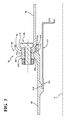
- FIG. 8 is a sectional top view of the flange joint.
- FIG. 1 schematically illustrates a gas turbine engine 20 .
- the gas turbine engine 20 is disclosed herein as a two-spool turbofan that generally incorporates a fan section 22 , a compressor section 24 , a combustor section 26 and a turbine section 28 .
- Alternative engines architectures such as a low-bypass turbofan may include an augmentor section (not shown) among other systems or features.
- turbofan Although schematically illustrated as a turbofan in the disclosed non-limiting embodiment, it should be understood that the concepts described herein are not limited to use with turbofans as the teachings may be applied to other types of turbine engines to include, but not limited to, a three-spool (plus fan) engine as well as other engine architectures such as turbojets, turboshafts, open rotors and industrial gas turbines.
- the fan section 22 drives air along a bypass flowpath and a core flowpath.
- the compressor section 24 compresses air along the core flowpath for communication into the combustor section 26 then expansion through the turbine section 28 .
- the engine 20 generally includes a low spool 30 and a high spool 32 mounted for rotation about an engine central longitudinal axis A relative to an engine case assembly 36 via several bearing compartments 38 .
- the low spool 30 generally includes an inner shaft 40 that interconnects a fan 42 , a low-pressure compressor (“LPC”) 44 and a low-pressure turbine (“LPT”) 46 .
- the inner shaft 40 drives the fan 42 either directly or through a geared architecture 48 to drive the fan 42 at a lower speed than the low spool 30 .
- the high spool 32 includes an outer shaft 50 that interconnects a high-pressure compressor (“HPC”) 52 and high-pressure turbine (“HPT”) 54 .
- a combustor 56 is arranged between the HPC 52 and the HPT 54 . Core airflow is compressed by the LPC 44 then the HPC 52 , mixed with fuel and burned in the combustor 56 , then expanded over the HPT 54 and the LPT 46 .
- the HPT 54 and the LPT 46 drive the respective high spool 32 and low spool 30 in response to the expansion.
- the inner shaft 40 and the outer shaft 50 are concentric and rotate about the engine central longitudinal axis A that is collinear with their longitudinal axes.
- the gas turbine engine 20 is a high-bypass geared architecture engine in which the bypass ratio is greater than about six (6:1).
- the geared architecture 48 can include an epicyclic gear system 48 , such as a planetary gear system, star gear system or other system.
- the example epicyclic gear train has a gear reduction ratio of greater than about 2.3, and in another example is greater than about 2.5 with a gear system efficiency greater than approximately 98%.
- the geared turbofan enables operation of the low spool 30 at higher speeds which can increase the operational efficiency of the LPC 44 and LPT 46 and render increased pressure in a fewer number of stages.
- a pressure ratio associated with the LPT 46 is pressure measured prior to the inlet of the LPT 46 as related to the pressure at the outlet of the LPT 46 prior to an exhaust nozzle of the gas turbine engine 20 .
- the bypass ratio of the gas turbine engine 20 is greater than about ten (10:1)
- the fan diameter is significantly larger than that of the LPC 44
- the LPT 46 has a pressure ratio that is greater than about five (5:1). It should be understood, however, that the above parameters are only exemplary of one embodiment of a geared architecture engine and that the present disclosure is applicable to other gas turbine engines including direct drive turbofans.
- a significant amount of thrust is provided by the bypass flow due to the high bypass ratio.
- the fan section 22 of the gas turbine engine 20 is designed for a particular flight condition—typically cruise at about 0.8 Mach and about 35,000 feet. This flight condition, with the gas turbine engine 20 at its best fuel consumption, is also known as bucket cruise Thrust Specific Fuel Consumption (TSFC).
- TSFC Thrust Specific Fuel Consumption
- Fan Pressure Ratio is the pressure ratio across a blade of the fan section 22 without a Fan Exit Guide Vane system.
- the low Fan Pressure Ratio according to one non-limiting embodiment of the example gas turbine engine 20 is less than 1.45.
- Low Corrected Fan Tip Speed is the actual fan tip speed divided by an industry standard temperature correction of (“T”/518.7) 0.5 in which “T” represents the ambient temperature in degrees Rankine.
- the Low Corrected Fan Tip Speed according to one non-limiting embodiment of the example gas turbine engine 20 is less than about 1150 fps (351 m/s).
- the engine case assembly 36 generally includes a plurality of cases, including a fan case 60 , an intermediate case 62 , a Low Pressure Compressor (LPC) case 64 , a High Pressure Compressor (HPC) case 66 , a diffuser case 68 , a High Pressure Turbine (HPT) case 70 , a mid-turbine frame (MTF) case 72 , a Low Pressure Turbine (LPT) case 74 , and a Turbine Exhaust Case (TEC) case 76 .
- LPC Low Pressure Compressor
- HPC High Pressure Compressor
- HPC High Pressure Compressor
- HPT High Pressure Turbine
- MTF mid-turbine frame
- LPT Low Pressure Turbine
- TEC Turbine Exhaust Case
- each case is assembled to an adjacent case at a respective flange 80 , 82 , via a plurality of fasteners 100 (one shown) that are installed in respective apertures 120 , 122 to form flanged joint 78 .
- fasteners 100 one shown
- any flange joint interface 130 such as between each or any of the above delineated cases will benefit herefrom.
- the diffuser flange 80 generally includes a radial flange portion 140 and a seal lip 142 that extend transverse thereto.
- the seal lip 142 extends longitudinally with respect to the engine axis A and is perpendicular to the radial flange portion 140 .
- the seal lip 142 is arranged to at least partially overlap the HPT case 70 and is directed in a downstream direction to interface with the HPT case 70 at a longitudinal interface 144 to seal a radial interface 146 between the flanges 80 , 82 . That is, the longitudinal interface 144 extends axially beyond the radial interface 146 .
- the seal lip 142 may include an undercut 188 to ensure the seal snap occurs on the uninterrupted (in circumferential direction) surface 189 ( FIG. 6 ).
- an undercut 191 may be located on the flange 82 ( FIG. 7 ).
- the radial flange portion 140 defines a thickness of about 0.26 inch (6.6 mm). Such a thickness facilitates coating repair, such as via plasma spray, which may be required whenever the diffuser case 68 and the HPT cases 70 are separated.
- a heat shield 210 includes a distal end 212 that interfaces with a step 214 in the diffuser case 68 forward of the radial flange portion 140 .
- the interface location of the heat shield 210 thereby facilitates shielding of the radial interface 146 from high speed/high pressure flow to minimize heat transfer at flange. That is, the heat shield 210 is radially inboard of the seal lip 142 .
- a radial flange portion 148 includes a scallop 150 along an outer diameter 160 to flank each aperture 122 . This facilitates a reduction of the stress on the aperture 122 near the outer diameter 160 .
- Each aperture 120 , 122 in one example, is about 0.34 inch (8.6 mm) in diameter.
- Each scallop 150 extends for the entire thickness of the radial flange portion 148 and, in one example, defines a radius of about 0.25 inch (6.35 mm). That is, the scallop 150 is of a most generous radius related to the number of apertures and space therebetween to provide a desired web thickness.
- the radial flange portion 148 further includes a partial scallop 180 along an inner diameter 190 of the radial flange portion 148 to flank each aperture 122 . This further facilitates a reduction of the stress on the flange 82 .
- Each partial scallop 180 is about half the thickness of the radial flange portion 148 .
- “partial” refers to the partial scallop 180 that does not extend through the entirety of the thickness of the radial flange portion 148 .
- Each partial scallop 180 in one example, also defines a radius of about 0.25 inch (6.35 mm).
- the enjoyment of the scallop 150 , and the partial scallop 180 may be sized to form a circle “C” that surrounds the aperture 122 and extends from the outer diameter 160 to the inner diameter 190 ( FIG. 5 ).
- a web thickness around the aperture 122 in the radial flange is approximately equivalent with respect to the inner diameter 190 , the outer diameter 160 , the partial scallops 180 and the scallops 150 . It should be appreciated that various other radiuses may be provided.
- An inner scallop fillet radius 186 in one example, is about 0.25 inch (6.35 mm) is also formed from a face 192 of the radial flange portion 148 (also shown in FIG. 6 and FIG. 7 ).
- the inner scallop fillet radius 186 is also provided as a generous radius that, in one example, is about 0.5 that of the depth of the partial scallops 180 . That is, the inner scallop fillet radius 186 is a relatively large transition to minimize stress formations and may essentially form a semi-spherical shape.
- the partial scallops 180 readily increase Low Cycle Fatigue (LCF) life of the apertures 122 .
- LCF Low Cycle Fatigue
- the apertures 120 , 122 receives the respective fastener 100 that, in one example, includes a “D” head bolt 202 that is 0.3125′′ (7.9 mm) in diameter.
- the “D” head bolt 202 facilitates a reduced radial height of the radial flange portions 140 , 148 and operates as an anti-rotation feature to facilitate receipt and removal of a nut 204 .
Abstract
Description
Claims (14)
Priority Applications (2)
| Application Number | Priority Date | Filing Date | Title |
|---|---|---|---|
| US14/735,299 US9856753B2 (en) | 2015-06-10 | 2015-06-10 | Inner diameter scallop case flange for a case of a gas turbine engine |
| EP16174009.7A EP3103972B1 (en) | 2015-06-10 | 2016-06-10 | Gas turbine engine case comprising a radial flange with partial scallops |
Applications Claiming Priority (1)
| Application Number | Priority Date | Filing Date | Title |
|---|---|---|---|
| US14/735,299 US9856753B2 (en) | 2015-06-10 | 2015-06-10 | Inner diameter scallop case flange for a case of a gas turbine engine |
Publications (2)
| Publication Number | Publication Date |
|---|---|
| US20160363004A1 US20160363004A1 (en) | 2016-12-15 |
| US9856753B2 true US9856753B2 (en) | 2018-01-02 |
Family
ID=56117647
Family Applications (1)
| Application Number | Title | Priority Date | Filing Date |
|---|---|---|---|
| US14/735,299 Active 2036-03-07 US9856753B2 (en) | 2015-06-10 | 2015-06-10 | Inner diameter scallop case flange for a case of a gas turbine engine |
Country Status (2)
| Country | Link |
|---|---|
| US (1) | US9856753B2 (en) |
| EP (1) | EP3103972B1 (en) |
Cited By (4)
| Publication number | Priority date | Publication date | Assignee | Title |
|---|---|---|---|---|
| US11021999B2 (en) * | 2015-12-24 | 2021-06-01 | Mitsubishi Heavy Industries Aero Engines, Ltd. | Gas turbine combustor casing having a projection part |
| US11359513B2 (en) | 2017-02-28 | 2022-06-14 | Siemens Energy Global GmbH & Co. KG | Turbine casing and method for assembling a turbine having a turbine casing |
| US11421555B2 (en) | 2018-12-07 | 2022-08-23 | Raytheon Technologies Corporation | Case flange with scallop features |
| US20220268177A1 (en) * | 2019-07-15 | 2022-08-25 | Abb Switzerland Ltd. | Turbine casing comprising a low-stress connection flange, and exhaust-gas turbine having such a turbine casing |
Families Citing this family (9)
| Publication number | Priority date | Publication date | Assignee | Title |
|---|---|---|---|---|
| FR3055655B1 (en) * | 2016-09-06 | 2019-04-05 | Safran Aircraft Engines | INTERMEDIATE CASE OF TURBOMACHINE TURBINE |
| US20180223691A1 (en) * | 2017-02-03 | 2018-08-09 | United Technologies Corporation | Case flange with stress reducing features |
| US20190091753A1 (en) * | 2017-09-28 | 2019-03-28 | United Technologies Corporation | Systems and methods for treating an engine flange |
| US10774685B2 (en) * | 2018-04-30 | 2020-09-15 | Ratheon Technologies Corporation | Gas turbine engine exhaust component |
| US11015636B2 (en) * | 2018-07-03 | 2021-05-25 | Raytheon Technologies Corporation | Nut strip assembly with array of captured nuts |
| US11428124B2 (en) * | 2018-11-21 | 2022-08-30 | Raytheon Technologies Corporation | Flange stress-reduction features |
| EP3715590A1 (en) * | 2019-03-27 | 2020-09-30 | Siemens Aktiengesellschaft | Turbomachinery housing assembly |
| US11162425B2 (en) * | 2019-06-11 | 2021-11-02 | Rolls-Royce Corporation | Assembly fixture |
| CN114207255A (en) * | 2019-07-30 | 2022-03-18 | 西门子能源全球两合公司 | High temperature flange joint, exhaust diffuser and method of coupling two components of a gas turbine engine |
Citations (35)
| Publication number | Priority date | Publication date | Assignee | Title |
|---|---|---|---|---|
| US1341969A (en) * | 1919-10-09 | 1920-06-01 | Richard A Breul | Doorknob |
| US2650552A (en) * | 1950-11-01 | 1953-09-01 | Frank T Wood | Dough rolling apparatus |
| US3068026A (en) * | 1958-06-13 | 1962-12-11 | Gen Motors Corp | Cryogenic fluid transfer line coupling |
| US3746374A (en) * | 1969-12-09 | 1973-07-17 | Lucas Industries Ltd | Joint arrangements |
| US4552386A (en) * | 1983-08-22 | 1985-11-12 | United Technologies Corporation | Joints between cylinders of different materials |
| US4643047A (en) * | 1981-10-20 | 1987-02-17 | Advanced Energy Concepts '81 Ltd. | Speed reducing gearing mechanism employing trochoidally formed gear surfaces for rolling torque transmission |
| US4840026A (en) * | 1988-02-24 | 1989-06-20 | The United States Of America As Represented By The Secretary Of The Air Force | Band clamp apparatus |
| US5230540A (en) * | 1989-03-15 | 1993-07-27 | Rolls-Royce Plc | Fluid-tight joint with inclined flange face |
| US5288206A (en) * | 1991-11-20 | 1994-02-22 | Societe Nationale D'etude Et De Construction De Moteurs D'aviation S.N.E.C.M.A. | Turbo aero engine equipped with means facilitating adjustment of plays of the stator and between the stator and rotor |
| US5353674A (en) * | 1993-01-13 | 1994-10-11 | Peavey Electronics Corp. | Shell resonant membranophone |
| US5411369A (en) * | 1994-02-22 | 1995-05-02 | Pratt & Whitney Canada, Inc. | Gas turbine engine component retention |
| US5437482A (en) * | 1994-04-07 | 1995-08-01 | Curtis; Donald K. | Pipe adapter flange |
| US5645363A (en) * | 1994-04-15 | 1997-07-08 | Dana Corporation | Bearing cap and pump mounting flange for power take-off unit |
| US6364606B1 (en) | 2000-11-08 | 2002-04-02 | Allison Advanced Development Company | High temperature capable flange |
| US6658853B2 (en) * | 2001-09-12 | 2003-12-09 | Kawasaki Jukogyo Kabushiki Kaisha | Seal structure for combustor liner |
| US6752592B2 (en) | 2001-12-28 | 2004-06-22 | General Electric Company | Supplemental seal for the chordal hinge seals in a gas turbine |
| EP1749974A2 (en) | 2005-08-06 | 2007-02-07 | General Electric Company | Thermally compliant turbine shroud mounting |
| US20090180864A1 (en) | 2008-01-14 | 2009-07-16 | Ioannis Alvanos | Gas turbine engine case |
| US20100152729A1 (en) * | 2008-12-16 | 2010-06-17 | Gallo Sr David P | Ablator with scalloped electrode and swaged tube |
| US8092164B2 (en) | 2007-08-30 | 2012-01-10 | United Technologies Corporation | Overlap interface for a gas turbine engine composite engine case |
| US8197186B2 (en) | 2007-06-29 | 2012-06-12 | General Electric Company | Flange with axially extending holes for gas turbine engine clearance control |
| US8206102B2 (en) | 2007-08-16 | 2012-06-26 | United Technologies Corporation | Attachment interface for a gas turbine engine composite duct structure |
| EP2469043A2 (en) | 2010-12-22 | 2012-06-27 | United Technologies Corporation | Axial retention feature for gas turbine engine vanes |
| US8257039B2 (en) | 2008-05-02 | 2012-09-04 | United Technologies Corporation | Gas turbine engine case with replaced flange and method of repairing the same using cold metal transfer |
| US8393855B2 (en) | 2007-06-29 | 2013-03-12 | General Electric Company | Flange with axially curved impingement surface for gas turbine engine clearance control |
| US8443514B2 (en) | 2007-04-02 | 2013-05-21 | Ansaldo Energia S.P.A. | Maintenance method of a gas turbine unit and gas turbine unit |
| US8459941B2 (en) * | 2009-06-15 | 2013-06-11 | General Electric Company | Mechanical joint for a gas turbine engine |
| US20140133976A1 (en) * | 2012-11-15 | 2014-05-15 | Techspace Aero S.A. | Radial Fixing and Positioning Flanges for Shells of Axial Turbine Compressor Housings |
| US8726675B2 (en) * | 2007-09-07 | 2014-05-20 | The Boeing Company | Scalloped flexure ring |
| US8899051B2 (en) | 2010-12-30 | 2014-12-02 | Rolls-Royce Corporation | Gas turbine engine flange assembly including flow circuit |
| WO2015047495A2 (en) | 2013-07-11 | 2015-04-02 | United Technologies Corporation | Flange partial section replacement repair |
| US20150143813A1 (en) * | 2013-11-22 | 2015-05-28 | Anil L. Salunkhe | Industrial gas turbine exhaust system with splined profile tail cone |
| US20150143816A1 (en) * | 2013-11-22 | 2015-05-28 | Anil L. Salunkhe | Modular industrial gas turbine exhaust system |
| US20150143814A1 (en) * | 2013-11-22 | 2015-05-28 | John A. Orosa | Industrial gas turbine exhaust system with area ruled exhaust path |
| US20150167498A1 (en) * | 2013-12-13 | 2015-06-18 | Rolls-Royce Deutschland Ltd & Co Kg | Joint between components |
-
2015
- 2015-06-10 US US14/735,299 patent/US9856753B2/en active Active
-
2016
- 2016-06-10 EP EP16174009.7A patent/EP3103972B1/en active Active
Patent Citations (37)
| Publication number | Priority date | Publication date | Assignee | Title |
|---|---|---|---|---|
| US1341969A (en) * | 1919-10-09 | 1920-06-01 | Richard A Breul | Doorknob |
| US2650552A (en) * | 1950-11-01 | 1953-09-01 | Frank T Wood | Dough rolling apparatus |
| US3068026A (en) * | 1958-06-13 | 1962-12-11 | Gen Motors Corp | Cryogenic fluid transfer line coupling |
| US3746374A (en) * | 1969-12-09 | 1973-07-17 | Lucas Industries Ltd | Joint arrangements |
| US4643047A (en) * | 1981-10-20 | 1987-02-17 | Advanced Energy Concepts '81 Ltd. | Speed reducing gearing mechanism employing trochoidally formed gear surfaces for rolling torque transmission |
| US4552386A (en) * | 1983-08-22 | 1985-11-12 | United Technologies Corporation | Joints between cylinders of different materials |
| US4840026A (en) * | 1988-02-24 | 1989-06-20 | The United States Of America As Represented By The Secretary Of The Air Force | Band clamp apparatus |
| US5230540A (en) * | 1989-03-15 | 1993-07-27 | Rolls-Royce Plc | Fluid-tight joint with inclined flange face |
| US5288206A (en) * | 1991-11-20 | 1994-02-22 | Societe Nationale D'etude Et De Construction De Moteurs D'aviation S.N.E.C.M.A. | Turbo aero engine equipped with means facilitating adjustment of plays of the stator and between the stator and rotor |
| US5353674A (en) * | 1993-01-13 | 1994-10-11 | Peavey Electronics Corp. | Shell resonant membranophone |
| US5411369A (en) * | 1994-02-22 | 1995-05-02 | Pratt & Whitney Canada, Inc. | Gas turbine engine component retention |
| US5437482A (en) * | 1994-04-07 | 1995-08-01 | Curtis; Donald K. | Pipe adapter flange |
| US5645363A (en) * | 1994-04-15 | 1997-07-08 | Dana Corporation | Bearing cap and pump mounting flange for power take-off unit |
| US6364606B1 (en) | 2000-11-08 | 2002-04-02 | Allison Advanced Development Company | High temperature capable flange |
| US6658853B2 (en) * | 2001-09-12 | 2003-12-09 | Kawasaki Jukogyo Kabushiki Kaisha | Seal structure for combustor liner |
| US6752592B2 (en) | 2001-12-28 | 2004-06-22 | General Electric Company | Supplemental seal for the chordal hinge seals in a gas turbine |
| EP1749974A2 (en) | 2005-08-06 | 2007-02-07 | General Electric Company | Thermally compliant turbine shroud mounting |
| US8443514B2 (en) | 2007-04-02 | 2013-05-21 | Ansaldo Energia S.P.A. | Maintenance method of a gas turbine unit and gas turbine unit |
| US8197186B2 (en) | 2007-06-29 | 2012-06-12 | General Electric Company | Flange with axially extending holes for gas turbine engine clearance control |
| US8393855B2 (en) | 2007-06-29 | 2013-03-12 | General Electric Company | Flange with axially curved impingement surface for gas turbine engine clearance control |
| US8596972B2 (en) | 2007-08-16 | 2013-12-03 | United Technologies Corporation | Attachment interface for a gas turbine engine composite duct structure |
| US8206102B2 (en) | 2007-08-16 | 2012-06-26 | United Technologies Corporation | Attachment interface for a gas turbine engine composite duct structure |
| US8092164B2 (en) | 2007-08-30 | 2012-01-10 | United Technologies Corporation | Overlap interface for a gas turbine engine composite engine case |
| US8726675B2 (en) * | 2007-09-07 | 2014-05-20 | The Boeing Company | Scalloped flexure ring |
| US20090180864A1 (en) | 2008-01-14 | 2009-07-16 | Ioannis Alvanos | Gas turbine engine case |
| US8257039B2 (en) | 2008-05-02 | 2012-09-04 | United Technologies Corporation | Gas turbine engine case with replaced flange and method of repairing the same using cold metal transfer |
| US20100152729A1 (en) * | 2008-12-16 | 2010-06-17 | Gallo Sr David P | Ablator with scalloped electrode and swaged tube |
| US8459941B2 (en) * | 2009-06-15 | 2013-06-11 | General Electric Company | Mechanical joint for a gas turbine engine |
| EP2469043A2 (en) | 2010-12-22 | 2012-06-27 | United Technologies Corporation | Axial retention feature for gas turbine engine vanes |
| US8596969B2 (en) * | 2010-12-22 | 2013-12-03 | United Technologies Corporation | Axial retention feature for gas turbine engine vanes |
| US8899051B2 (en) | 2010-12-30 | 2014-12-02 | Rolls-Royce Corporation | Gas turbine engine flange assembly including flow circuit |
| US20140133976A1 (en) * | 2012-11-15 | 2014-05-15 | Techspace Aero S.A. | Radial Fixing and Positioning Flanges for Shells of Axial Turbine Compressor Housings |
| WO2015047495A2 (en) | 2013-07-11 | 2015-04-02 | United Technologies Corporation | Flange partial section replacement repair |
| US20150143813A1 (en) * | 2013-11-22 | 2015-05-28 | Anil L. Salunkhe | Industrial gas turbine exhaust system with splined profile tail cone |
| US20150143816A1 (en) * | 2013-11-22 | 2015-05-28 | Anil L. Salunkhe | Modular industrial gas turbine exhaust system |
| US20150143814A1 (en) * | 2013-11-22 | 2015-05-28 | John A. Orosa | Industrial gas turbine exhaust system with area ruled exhaust path |
| US20150167498A1 (en) * | 2013-12-13 | 2015-06-18 | Rolls-Royce Deutschland Ltd & Co Kg | Joint between components |
Non-Patent Citations (1)
| Title |
|---|
| European Extended Search Report dated Oct. 25, 2016, issued in the corresponding European Patent Application No. 16174009.7. |
Cited By (5)
| Publication number | Priority date | Publication date | Assignee | Title |
|---|---|---|---|---|
| US11021999B2 (en) * | 2015-12-24 | 2021-06-01 | Mitsubishi Heavy Industries Aero Engines, Ltd. | Gas turbine combustor casing having a projection part |
| US11359513B2 (en) | 2017-02-28 | 2022-06-14 | Siemens Energy Global GmbH & Co. KG | Turbine casing and method for assembling a turbine having a turbine casing |
| US11421555B2 (en) | 2018-12-07 | 2022-08-23 | Raytheon Technologies Corporation | Case flange with scallop features |
| US20220268177A1 (en) * | 2019-07-15 | 2022-08-25 | Abb Switzerland Ltd. | Turbine casing comprising a low-stress connection flange, and exhaust-gas turbine having such a turbine casing |
| US11852030B2 (en) * | 2019-07-15 | 2023-12-26 | Turbo Systems Switzerland Ltd | Turbine casing comprising a low-stress connection flange, and exhaust-gas turbine having such a turbine casing |
Also Published As
| Publication number | Publication date |
|---|---|
| US20160363004A1 (en) | 2016-12-15 |
| EP3103972A1 (en) | 2016-12-14 |
| EP3103972B1 (en) | 2020-04-22 |
Similar Documents
| Publication | Publication Date | Title |
|---|---|---|
| US9856753B2 (en) | Inner diameter scallop case flange for a case of a gas turbine engine | |
| US10815898B2 (en) | Seal assembly for a static structure of a gas turbine engine | |
| US10100670B2 (en) | Heatshield assembly with double lap joint for a gas turbine engine | |
| EP2971688B1 (en) | Gas turbine engine disclosing a heat shield and method of mounting this heat shield | |
| US9879558B2 (en) | Low leakage multi-directional interface for a gas turbine engine | |
| US20150260404A1 (en) | Interface heat shield for a combustor of a gas turbine engine | |
| US9328626B2 (en) | Annular turbomachine seal and heat shield | |
| US20160333712A1 (en) | Chordal seal | |
| US9765649B2 (en) | Borescope inspection port fitting | |
| EP2971677B1 (en) | Triple flange arrangement for a gas turbine engine | |
| US11066953B2 (en) | Multi-ply heat shield assembly with integral band clamp for a gas turbine engine | |
| US11008890B2 (en) | Sealing interface for a case of a gas turbine engine | |
| US20140260321A1 (en) | Gas turbine engine static structure joint with undercuts | |
| US10378371B2 (en) | Anti-rotation vane | |
| US20180045218A1 (en) | Shim for gas turbine engine | |
| US11649729B2 (en) | Anti-vortex tube retaining ring and bore basket | |
| EP2955332B1 (en) | Geared turbofan engine with gearbox seal | |
| EP3597870B1 (en) | Gas turbine engine | |
| EP3073060B1 (en) | Seal support structures for turbomachines |
Legal Events
| Date | Code | Title | Description |
|---|---|---|---|
| AS | Assignment |
Owner name: UNITED TECHNOLOGIES CORPORATION, CONNECTICUT Free format text: ASSIGNMENT OF ASSIGNORS INTEREST;ASSIGNORS:CHOW, WAI TUCK;IVANOV, OLEG;PRIHAR, RON I;SIGNING DATES FROM 20150520 TO 20150522;REEL/FRAME:035814/0513 |
|
| STCF | Information on status: patent grant |
Free format text: PATENTED CASE |
|
| AS | Assignment |
Owner name: RAYTHEON TECHNOLOGIES CORPORATION, MASSACHUSETTS Free format text: CHANGE OF NAME;ASSIGNOR:UNITED TECHNOLOGIES CORPORATION;REEL/FRAME:054062/0001 Effective date: 20200403 |
|
| AS | Assignment |
Owner name: RAYTHEON TECHNOLOGIES CORPORATION, CONNECTICUT Free format text: CORRECTIVE ASSIGNMENT TO CORRECT THE AND REMOVE PATENT APPLICATION NUMBER 11886281 AND ADD PATENT APPLICATION NUMBER 14846874. TO CORRECT THE RECEIVING PARTY ADDRESS PREVIOUSLY RECORDED AT REEL: 054062 FRAME: 0001. ASSIGNOR(S) HEREBY CONFIRMS THE CHANGE OF ADDRESS;ASSIGNOR:UNITED TECHNOLOGIES CORPORATION;REEL/FRAME:055659/0001 Effective date: 20200403 |
|
| MAFP | Maintenance fee payment |
Free format text: PAYMENT OF MAINTENANCE FEE, 4TH YEAR, LARGE ENTITY (ORIGINAL EVENT CODE: M1551); ENTITY STATUS OF PATENT OWNER: LARGE ENTITY Year of fee payment: 4 |
|
| AS | Assignment |
Owner name: RTX CORPORATION, CONNECTICUT Free format text: CHANGE OF NAME;ASSIGNOR:RAYTHEON TECHNOLOGIES CORPORATION;REEL/FRAME:064714/0001 Effective date: 20230714 |