US9856419B2 - Stable phosphors for lighting applications - Google Patents
Stable phosphors for lighting applications Download PDFInfo
- Publication number
- US9856419B2 US9856419B2 US14/419,704 US201214419704A US9856419B2 US 9856419 B2 US9856419 B2 US 9856419B2 US 201214419704 A US201214419704 A US 201214419704A US 9856419 B2 US9856419 B2 US 9856419B2
- Authority
- US
- United States
- Prior art keywords
- geo
- naca
- excitation
- shows
- emission
- Prior art date
- Legal status (The legal status is an assumption and is not a legal conclusion. Google has not performed a legal analysis and makes no representation as to the accuracy of the status listed.)
- Active, expires
Links
Images


Classifications
-
- C—CHEMISTRY; METALLURGY
- C09—DYES; PAINTS; POLISHES; NATURAL RESINS; ADHESIVES; COMPOSITIONS NOT OTHERWISE PROVIDED FOR; APPLICATIONS OF MATERIALS NOT OTHERWISE PROVIDED FOR
- C09K—MATERIALS FOR MISCELLANEOUS APPLICATIONS, NOT PROVIDED FOR ELSEWHERE
- C09K11/00—Luminescent, e.g. electroluminescent, chemiluminescent materials
- C09K11/08—Luminescent, e.g. electroluminescent, chemiluminescent materials containing inorganic luminescent materials
- C09K11/77—Luminescent, e.g. electroluminescent, chemiluminescent materials containing inorganic luminescent materials containing rare earth metals
- C09K11/7728—Luminescent, e.g. electroluminescent, chemiluminescent materials containing inorganic luminescent materials containing rare earth metals containing europium
- C09K11/7735—Germanates
-
- C—CHEMISTRY; METALLURGY
- C09—DYES; PAINTS; POLISHES; NATURAL RESINS; ADHESIVES; COMPOSITIONS NOT OTHERWISE PROVIDED FOR; APPLICATIONS OF MATERIALS NOT OTHERWISE PROVIDED FOR
- C09K—MATERIALS FOR MISCELLANEOUS APPLICATIONS, NOT PROVIDED FOR ELSEWHERE
- C09K11/00—Luminescent, e.g. electroluminescent, chemiluminescent materials
- C09K11/08—Luminescent, e.g. electroluminescent, chemiluminescent materials containing inorganic luminescent materials
- C09K11/66—Luminescent, e.g. electroluminescent, chemiluminescent materials containing inorganic luminescent materials containing germanium, tin or lead
- C09K11/661—Chalcogenides
- C09K11/663—Chalcogenides with alkaline earth metals
-
- C—CHEMISTRY; METALLURGY
- C09—DYES; PAINTS; POLISHES; NATURAL RESINS; ADHESIVES; COMPOSITIONS NOT OTHERWISE PROVIDED FOR; APPLICATIONS OF MATERIALS NOT OTHERWISE PROVIDED FOR
- C09K—MATERIALS FOR MISCELLANEOUS APPLICATIONS, NOT PROVIDED FOR ELSEWHERE
- C09K11/00—Luminescent, e.g. electroluminescent, chemiluminescent materials
- C09K11/08—Luminescent, e.g. electroluminescent, chemiluminescent materials containing inorganic luminescent materials
- C09K11/77—Luminescent, e.g. electroluminescent, chemiluminescent materials containing inorganic luminescent materials containing rare earth metals
- C09K11/7715—Luminescent, e.g. electroluminescent, chemiluminescent materials containing inorganic luminescent materials containing rare earth metals containing cerium
- C09K11/7716—Chalcogenides
- C09K11/7718—Chalcogenides with alkaline earth metals
-
- C—CHEMISTRY; METALLURGY
- C09—DYES; PAINTS; POLISHES; NATURAL RESINS; ADHESIVES; COMPOSITIONS NOT OTHERWISE PROVIDED FOR; APPLICATIONS OF MATERIALS NOT OTHERWISE PROVIDED FOR
- C09K—MATERIALS FOR MISCELLANEOUS APPLICATIONS, NOT PROVIDED FOR ELSEWHERE
- C09K11/00—Luminescent, e.g. electroluminescent, chemiluminescent materials
- C09K11/08—Luminescent, e.g. electroluminescent, chemiluminescent materials containing inorganic luminescent materials
- C09K11/77—Luminescent, e.g. electroluminescent, chemiluminescent materials containing inorganic luminescent materials containing rare earth metals
- C09K11/7743—Luminescent, e.g. electroluminescent, chemiluminescent materials containing inorganic luminescent materials containing rare earth metals containing terbium
- C09K11/775—Germanates
-
- H—ELECTRICITY
- H01—ELECTRIC ELEMENTS
- H01L—SEMICONDUCTOR DEVICES NOT COVERED BY CLASS H10
- H01L33/00—Semiconductor devices with at least one potential-jump barrier or surface barrier specially adapted for light emission; Processes or apparatus specially adapted for the manufacture or treatment thereof or of parts thereof; Details thereof
- H01L33/48—Semiconductor devices with at least one potential-jump barrier or surface barrier specially adapted for light emission; Processes or apparatus specially adapted for the manufacture or treatment thereof or of parts thereof; Details thereof characterised by the semiconductor body packages
- H01L33/50—Wavelength conversion elements
- H01L33/501—Wavelength conversion elements characterised by the materials, e.g. binder
- H01L33/502—Wavelength conversion materials
-
- H—ELECTRICITY
- H05—ELECTRIC TECHNIQUES NOT OTHERWISE PROVIDED FOR
- H05B—ELECTRIC HEATING; ELECTRIC LIGHT SOURCES NOT OTHERWISE PROVIDED FOR; CIRCUIT ARRANGEMENTS FOR ELECTRIC LIGHT SOURCES, IN GENERAL
- H05B33/00—Electroluminescent light sources
- H05B33/12—Light sources with substantially two-dimensional radiating surfaces
- H05B33/14—Light sources with substantially two-dimensional radiating surfaces characterised by the chemical or physical composition or the arrangement of the electroluminescent material, or by the simultaneous addition of the electroluminescent material in or onto the light source
Definitions
- Phosphors are materials capable of emitting photoluminescence when excited by radiation. They are used in LEDs, cathode ray tubes and sensors. LEDs are extensively used for applications in industrial and domestic lighting, indicator lights, traffic signs, automotive dashboards, and portable flash lights. Phosphors for lighting applications can be made in two ways: doping with activator ions or self-activation. Activator doped phosphors are prepared by doping activator ions in small concentrations into a host material.
- photoluminescence By direct excitation with light or by subsequent energy transfer, electrons populate the excited energy levels of the activator ions, and when they revert to the ground state, light emission referred to as photoluminescence takes place.
- the emitted radiation can have higher (“up-conversion”) or lower (“down-conversion”) energy than the energy of the excitation light.
- the photoluminescence is based on electron activation within subunits of the structure.
- Self-activating CaWO 4 has a blue emission band centered at about 420 nm which is caused by charge transfer within WO 4 2 ⁇ complexes, where the oxygen 2p electrons partially occupy the empty 5d orbitals of tungsten.
- Rare earth activated phosphors show line emission when excited by UV radiation, which causes the electrons to absorb photons and excite them to higher energy levels. Subsequently they relax back to the lowest vibrational energy level of the first excited state before finally returning to the ground state by emitting energy in the form of light. A broad band emission occurs when there is a shift in the equilibrium position upon excitation by photon absorption.
- the most widely used phosphors for LEDs currently are oxides (e.g., Ce 3+ -doped Y 3 Ga 5 O 12 , Lu 3 Al 5 O 12 , Gd 3 Sc 2 A l3 O 12 and Ca 3 Sc 2 Si 3 O 12 ), nitrides (e.g., Sr 2 Si 5 N 8 , SiN 4 ), or sulfides (e.g., SrS:Eu 2+ , SrGaS 4 :Eu 2+ .
- oxides e.g., Ce 3+ -doped Y 3 Ga 5 O 12 , Lu 3 Al 5 O 12 , Gd 3 Sc 2 A l3 O 12 and Ca 3 Sc 2 Si 3 O 12
- nitrides e.g., Sr 2 Si 5 N 8 , SiN 4
- sulfides e.g., SrS:Eu 2+ , SrGaS 4 :Eu 2+ .
- Y 3 Al 5 O 12 :Ce 3+ (YAG:Ce 3+ )) that are used as a phosphor for blue-emitting In x Ga 1 ⁇ x N based LEDs as it efficiently absorbs part of the blue light and then emits bright yellow light to create cold white light.
- Thermal quenching processes occur when electrons in a material are excited and relax back to the ground state by nonradiative transitions since the excited state and ground state energy parabolas cross energies thermally accessible from the excited state. The excited electron reaches the ground state without emitting light and the photoluminescence intensity decreases as a consequence.
- nitride and/or oxynitride based phosphors e.g. Sr 2 Al 2 Si 10 N 14 O 4 :Eu 2+ have high efficiencies and chemical as well as thermal stability, these materials need to be prepared using complex and expensive synthesis conditions.
- Fluoride phosphors such as K 2 TiF 6 :Mn 4+ , K 2 SiF 6 :Mn 4+ , NaYF 4 doped with Yb 3+ , Er 3+ , Tm 3+ , are not very stable materials in air and humidity. Oxyfluorides are more stable compounds than fluorides with respect to hydrolysis. The presence of fluorine in the structure positively affects the photoluminescence properties of the phosphors: due to the ‘softer’ phonon modes at lower energies associated with the fluorine atoms in the lattice, thermal quenching is often reduced.
- Magnesium fluorogermanate is an oxyfluoride studied previously whose structural units are the same as those present in NaCa 2 GeO 4 F namely F ⁇ anions and GeO 4 tetrahedral units.
- Magnesium germanate phosphors containing only GeO 4 tetrahedral subunits were discovered as early as 1936 by Leverenz, who prepared weakly luminescent Mn 4+ ( 4 A 2g to 4 T 1g and to 4 T 2g transitions) doped meta-magnesium germanate (MgGeO 3 ) and ortho-magnesium germanate (Mg 2 GeO 4 ).
- Mg 28 Ge 7.5 O 38 F 10 there are some vacancies in the Ge sites when compared to the Mg 28 Ge 10 O 48 structure and the F ⁇ anions substitute for some O 2 ⁇ sites for reasons of charge compensation.
- Ge 4+ cations are tetrahedrally coordinated by oxygen and located on two sites.
- the Mn 4+ activator occupies both the octahedral Ge 4+ sites and the Mg 2+ sites. This phosphor was subsequently used by Westinghouse Electric Company.
- NaCa 2 GeO 4 F The synthesis of NaCa 2 GeO 4 F was first reported by Schneemeyer et al. in 2001 and its structure is described as a hexagonal antiperovskite.
- An antiperovskite is a perovskite where the cation and anion sites are interchanged.
- these materials can be written as (XO 4 )FSr 3 .
- Sr 3 XO 4 F structures instead of face sharing as in NaCa 2 GeO 4 F, Sr 3 XO 4 F structures have corner sharing octahedra.
- compositions are generally provided that include an oxyfluoride compound.
- the oxyfluoride compound has the formula: NaCa 2 ⁇ x A x GeO 4 ⁇ z F 1 ⁇ y N z where A is Ba, Sr, or a mixture thereof; 0.01 ⁇ x ⁇ 0.1 (e.g., 0.01 ⁇ x ⁇ 0.06); 0 ⁇ y ⁇ 0.2; and 0 ⁇ z ⁇ 0.1.
- z is 0, and/or y is 0.
- the oxyfluoride compound can, in one embodiment, have the formula: NaCa 2 ⁇ x A x GeO 4 F wherein A is Ba, Sr, or a mixture thereof; and wherein 0.01 ⁇ x ⁇ 0.1 (e.g., 0.01 ⁇ x ⁇ 0.06).
- An activator ion can be, in one embodiment, coupled with the compound, such as ions of La, Ac, Ce, Pr, Nd, Sm, Eu, Gd, Tb, Dy, Ho, Er, Tm, Yb, Th, U, Cr, Mn, Tc, Re, Cu, Ag, Au, Zn, Cd, Hg, As, Sb, Bi, Ge, Sn, Pb, In, Tl, or mixtures thereof.
- the composition includes an oxyfluoride compound having the formula: NaCa 2 ⁇ x A x GeO 4 ⁇ z F 1 ⁇ y N z where A is Ba, Sr, or a mixture thereof; 0 ⁇ x ⁇ 0.1; 0 ⁇ y ⁇ 0.2; and 0 ⁇ z ⁇ 0.1; and an activator ion coupled with the compound.
- x can be 0; z can be 0; and/or y can be 0.
- the activator ion can be an ion of an element selected from the group consisting of La, Ac, Ce, Pr, Nd, Sm, Eu, Gd, Tb, Dy, Ho, Er, Tm, Yb, Th, U, Cr, Mn, Tc, Re, Cu, Ag, Au, Zn, Cd, Hg, As, Sb, Bi, Ge, Sn, Pb, In, Tl, and mixtures thereof.
- the activator ion comprises an ion of Eu (e.g., Eu 3+ ), Ce (e.g., Ce 3+ ), Tb (e.g., Tb 3+ ), or a mixture thereof.
- Methods are also generally provided for doping a compound.
- the method can include, for example, introducing defects into a compound having the formula: NaCa 2 GeO 4 ⁇ z F 1 ⁇ y N z where 0 ⁇ y ⁇ 0.2; and 0 ⁇ z ⁇ 0.1, by substituting a portion of the Ca ions with ions of Ba, Sr, or a mixture thereof.
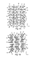
- FIG. 1 b shows the arrangement in NaCa 2 GeO 4 F in a view of the face-shared fluorine-centered octahedra in the a-c plane;
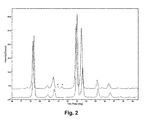
- FIG. 2 shows the XRD peaks of NaCa 1.955 Ba 0.045 GeO 4 F (bottom line) and NaCa 1.945 Ba 0.055 GeO 4 F (top line) with Ba 2 Ge 5 O 12 impurity peaks shown by asterisks;
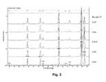
- FIG. 3 shows the XRD peaks for different mol fractions of Ba 2+ substitution
- FIG. 5 a shows a plot of lattice parameter a against y in NaCa 2 ⁇ y Sr y GeO 4 F;
- FIG. 5 b shows a plot of lattice parameter b against y in NaCa 2 ⁇ y Sr y GeO 4 F;
- FIG. 5 c shows a plot of lattice parameter c against y in NaCa 2 ⁇ y Sr y GeO 4 F;
- FIG. 6 shows the emission and excitation spectra of NaCa 2 GeO 4 F at 254 nm excitation and 422 nm emission;
- FIG. 7 shows the emission spectra of NaCa 1.985 Ba 0.015 GeO 4 F ( 72 ) and NaCa 2 GeO 4 F ( 70 ) under 254 nm excitation;
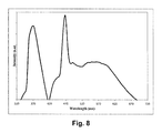
- FIG. 8 shows the emission spectra of NaCa 1.985 Ba 0.02 GeO 4 F under 365 nm excitation
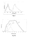
- FIG. 9 shows excitation and emission spectra of Na 1.01 Ca 1.98 Ce 0.01 GeO 4 F at 415 nm excitation and 555 nm emission;
- FIG. 10 a shows the Gaussian fitted emission spectra ( 30 ) of Na 1.02 Ca 1.98 Ce 0.02 GeO 4 F at 465 nm excitation and three Gaussian components ( 31 , 32 , 33 );
- FIG. 10 b shows the Gaussian-fitted emission spectra of Ca 2 GeO 4 :Ce 3+ ,Li + and its two Gaussian components
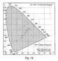
- FIG. 12 shows a CIE chromaticity diagram showing the corresponding CIE coordinates for various phosphors studied
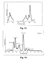
- FIG. 13 shows excitation and emission spectra of Na 1.05 Ca 1.9 Eu 0.05 GeO 4 F at 260 nm excitation;
- FIG. 14 shows emission spectra of NaCa 1.9 Li 0.05 Tb 0.03 Ce 0.02 GeO 4 F, at 254 nm excitation;
- FIG. 15 shows emission spectra of NaCa1.93Tb0.07Ge0.93Al0.07O4F at 254 nm excitation
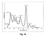
- FIG. 16 shows Emission spectra of Na1.07Ca1.86Tb0.07GeO4F at 270 nm excitation
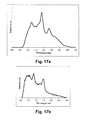
- FIG. 17 shows emission spectra of Na 0.1 Ca 1.8 Mn 0.1 Ce 0.04 GeO 4 F at (a) 220 nm excitation, (b) 365 nm and (c) 318 nm excitation;
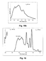
- FIG. 18 a and FIG. 18 b show[[s]] emission spectra of Na 1.02 Ca 1.95 Ba 0.02 Ce 0.02 GeO 4 F and Na 1.02 Ca 1.96 Ba 0.01 Ce 0.02 GeO 4 F at 365 nm excitation ( FIG. 18 a ) and Na 1.02 Ca 1.96 Ba 0.01 Ce 0.02 GeO 4 F at 254 nm excitation ( FIG. 18 b );
- FIG. 19 shows excitation and emission spectra of Na 1.01 Ca 1.97 Ba 0.01 Eu 0.01 GeO 4 F under 254 nm excitation;
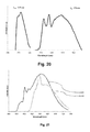
- FIG. 20 shows excitation and emission spectra of Na 1.02 Ca 1.94 Ba 0.02 Eu 0.02 GeO 4 F at 610 nm emission exhibiting peak at 378 nm;
- FIG. 21 shows emission spectra of Na 1.02 Ca 1.94 Ba 0.02 Eu 0.02 GeO 4 F at 365 nm and 420 nm excitation;
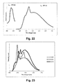
- FIG. 22 shows excitation and emission spectra of Na 1.02 Ca 1.94 Ba 0.02 Eu 0.02 GeO 4 F at 615 nm emission and 420 nm excitation;
- FIG. 23 shows emission spectra of Na 1.01 Ca 1.97 Ba 0.01 Eu 0.01 GeO 4 F at the excitation wavelengths of 365 nm, 378 nm and 412 nm;
- the present disclosure is directed to phosphors for use in light emitting devices.
- an ordered oxyfluoride compound is generally provided that has the formula: NaCa 2 ⁇ x A x GeO 4 ⁇ z F 1 ⁇ y N z where A is Ba, Sr, ora mixture thereof; 0.01 ⁇ x ⁇ 0.1 (e.g., 0.01 ⁇ x ⁇ 0.06); 0 ⁇ y ⁇ 0.2; and 0 ⁇ z ⁇ 0.1.
- z can be 0 (i.e., no nitrogen is present in the compound), and/or y can be 0.
- the oxyfluoride compound can have the formula: NaCa 2 ⁇ x A x GeO 4 F wherein A is Ba, Sr, or a mixture thereof; and wherein 0.01 ⁇ x ⁇ 0.1 (e.g., 0.01 ⁇ x ⁇ 0.06).
- a oxyfluoride compound is generally a compound formed from a base compound NaCa 2 GeO 4 F, substituted with Ba 2+ and/or Sr 2+ for Ca 2+ .
- A consists essentially of Ba (e.g., A consists of Ba).
- A consists essentially of Sr (e.g., A consists of Sr).
- Doped ordered oxyfluoride compounds are also generally provided.
- any of the substituted oxyfluoride compounds discussed above can be doped with an activator ion.
- the base oxyfluoride compound NaCa 2 GeO 4 F can be doped with an activator ion.
- Suitable activator ions for doping the oxyfluoride compounds include ions of La, Ac, Ce, Pr, Nd, Sm, Eu, Gd, Tb, Dy, Ho, Er, Tm, Yb, Th, U, Cr, Mn, Tc, Re, Cu, Ag, Au, Zn, Cd, Hg, As, Sb, Bi, Ge, Sn, Pb, In, Tl, or mixtures thereof.
- Particularly suitable activator ions for doping the oxyfluoride compounds are ions of Eu (e.g., Eu 3+ ), Ce (e.g., Ce 3+ ), Tb (e.g., Tb 3+ ), or mixtures thereof.
- Doping with rare earth elements allows white light emitting LEDs to be prepared by mixing green, blue and red light or yellow and blue light emitted from phosphors. Introducing suitable dopants in the oxyfluoride host lattice can result in the formation of novel down-conversion phosphors with desired emissions in the visible spectrum.
- NaCa 2 GeO 4 F has a large optical band gap (>3 eV) due to the energy difference between the oxygen 2p state and the Ca 3d and Ge 4s states. Having a large band gap is favorable for photoluminescence as both the ground and excited states of the activator ions can be accommodated within the electronic band gap of the host structure.
- Eu 3+ and Ce 3+ can be chosen for doping.
- the Eu 3+ ion is very efficient red light emitter mainly due to its 5 D 0 ⁇ 7 F 0 , 7 F 1 , 7 F 2 transitions.
- Ce 3+ doping can be used for its yellow emission due to its electronic transition from 5d 1 to 2 F 5/2 and 2 F 7/2 and its role as a sensitizer.
- Ce 3+ can act as a sensitizer when co-doped with Eu 2+ .
- a study done by Sivakumar et. al. on Sr 2 LiSiO 4 F has shown that, the co-doping of Ce 3+ increases the probability of the absorption of Eu 2+ in the UV to near-UV region as excitation spectra shows peaks at 830 and 330 nm.
- Bond valence sum (BVS) calculation is a method of determining bond strengths.
- the bond valence provides a metric to assess the stability of a structure.
- the atomic valence of an atom is equal to the sum of valences of all its bonds.
- R ij tabulated bond distance
- d ij is the observed bond distance
- b is an empirical constant
- the M1 and M2 (Ca/Na) sites have the same coordination environment.
- the formal valence of M1 is 1.7 (0.7 ⁇ 2+0.3 ⁇ 1) and the one for M2 is 1.76 (0.73 ⁇ 2+0.27 ⁇ 1).
- the M1 site has a BVS value of 1.87, and BVS of M2 is 1.91. These two sites can be partially substituted with Ba 2+ and Sr 2+ .
- Sr 2+ ion size is smaller (ionic radius 1.44 ⁇ ) than the Ba 2+ ion (ionic radius 1.61 ⁇ )
- Sr 2+ can substitute slightly more of Ca 2+ (ionic radius 1.34 ⁇ ) (>0.06 mol %) than Ba 2+ ( ⁇ 0.05 mol %).
- the NaCa 2 ⁇ x Ba x GeO 4 F samples prepared under reducing atmosphere are self-activating and shows yellow luminescence when excited with 254 nm UV light.
- This oxyfluoride material can be a phosphor when doped with lanthanides and/or rare earth elements.
- This oxyfluoride is chemically very stable and in its structure distinct crystallographic sites for metal ions are present which can be occupied with suitable dopants taking into consideration the charge and cation size of the host lattice metal and dopant element.
- NaCa 2 GeO 4 F was synthesized by combining stoichiometric amounts of CaCO 3 (99.95%), GeO 2 (99.99%), NaF (99.9%) in a mortar and pestle.
- the ground mixture was heated in a furnace from at 850° C. for 12 h in a flowing nitrogen atmosphere.
- the resulting powder was reground, pressed into a pellet, and again heated to 850° C. for 12 hours.
- Rare earth doping using Ce 3+ , Eu 3+ , and Tb 3+ was performed by mixed appropriate amounts of Ce 2 O 3 , Eu 2 O 3 and Tb 4 O 7 with the above mentioned starting materials and heated at 950° C.
- the structures formed were refined based upon X-ray powder diffraction data recorded on a Rigaku Miniflex X-ray diffractometer with a Cu-K ⁇ radiation source emitting a wavelength of 1.5406 ⁇ .
- the 2 ⁇ data were recorded from 3.0 to 149 degree in 2 ⁇ with a step size of 0.02.
- the X-ray data were analyzed by Rietveld refinement using the GSAS software package.
- Lattice parameters and atomic sites for NaCa 2 GeO 4 F in the orthorhombic Pnma space group were used as a starting model for the refinements.
- the atomic coordinates and isotropic displacement parameters of different atoms occupying the same site and the oxygen displacement parameters were constrained.
- the fractional occupancies were fixed to the nominal composition.
- the bond valence sum values calculated from the Schneemeyer data and our data are listed in Table 1.
- the BVS for M1 are almost equal, however, we observe a higher BVS value for M2 from our data due to a lower average Ca 2 —O bond distances than that found by Schneemeyer et. al. in their single crystal refinement.
- the Ge—O bond distances are higher in our case as indicated by a lower BVS for Ge.
- NaCa 2 GeO 4 F is quite stable in air and moisture, as the comparison of X-ray diffraction data of a freshly prepared NaCa 2 GeO 4 F and that of a 45 days old sample shows no significant change, but only a slight shrinkage of the lattice parameters of the aged sample.
- This chemical stability is in marked contrast to that observed for Sr 3 AlO 4 F which degrade over days when in contact with moisture and air.
- the formal valence of M1 is 1.7 (0.7 ⁇ 2+0.3 ⁇ 1) and the one for M2 is 1.76 (0.73 ⁇ 2+0.27 ⁇ 1).
- the M1 site has a BVS value of 1.87, and BVS of M2 is 1.91.
- These two sites can be partially substituted with Ba 2+ and Sr 2+ .
- Sr 2+ ion size is smaller (ionic radius 1.44 ⁇ ) than the Ba 2+ ion (ionic radius 1.61 ⁇ )
- Sr 2+ can substitute slightly more of Ca 2+ (ionic radius 1.34 ⁇ ) (>0.06 mol %) than Ba 2+ ( ⁇ 0.05 mol %).
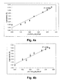
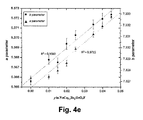
- the plot of the lattice parameters and unit cell volumes versus Ba 2+ concentrations indicate an almost linear behavior ( FIG. 4 ).
- Our refinements indicate that Ba 2+ is gradually substituting Ca 2+ in the M1 and M2 sites.
- the changing bond lengths and bond angles for the NaCa 2 ⁇ x Ba x GeO 4 F series are shown in Table 3.
- the BVS values for the atoms in the NaCa 2 ⁇ x Ba x GeO 4 F structures are listed in Table 4.
- the very small change in the BVS value for the M1 and M2 site with increasing Ba 2+ mol % indicate that the substitution of Ca 2+ by a very low concentration of Ba 2+ does not significantly affect the BVS values.
- FIG. 6 shows the excitation and emission spectra of undoped NaCa 2 GeO 4 F when excited with light at a wavelength of 240 nm.
- the undoped oxyfluoride material shows peaks at 422 nm, 468 nm and 540 nm which can be assigned to a oxygen deficient GeO 4 unit.
- NaCa 2 ⁇ x Ba x GeO 4 F family prepared under reducing condition are self-activating and show faint yellow luminescence under UV light.
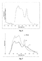
- a comparison of the emission spectra for NaCa 2 GeO 4 F and NaCa 1.985 Ba 0.015 GeO 4 F at 254 nm excitation is shown in FIG. 7 .
- NaCa 1.985 Ba 0.015 GeO 4 F exhibits a broad emission in 560-600 nm region.
- the emission spectra of NaCa 1.985 Ba 0.015 GeO 4 F at 365 nm excitation shows sharp peak at 464 nm and a broad peak in the 540 to 600 nm range.
- This material behaves very similar to Sr 2 ⁇ 2x Ce x Na x AlO 4 F as was observed by Chen et. al. which shows a blue green emission when excited at 405 nm. 11
- this compound Compared to Ca 2 GeO 4 :Ce 3+ ,Li + , this compound exhibits two emission peaks at 560 and 625 nm under 465 nm excitation ( FIG. 10 ). 29 The two distinct emission peaks are attributed to the fact that Ce 3+ ions occupying two distinct M sites.
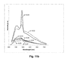
- the emission spectra of Ce 3+ doped NaCa 2 ⁇ 2x Ce x GeO 4 F (x 0.01, 0.02, 0.03, 0.04, 0.05) at 465 nm and at 430 nm excitation shows peaks near 550 nm and 625 nm with the strongest photoluminescence measured for Na 1.03 Ca 1.94 Ce 0.03 GeO 4 F, indicating concentration quenching at Ce 3+ concentrations above 0.03 mol % ( FIG. 11 ).
- the CIE coordinate values for different rare earth dopants (Ce 3+ , Eu 3+ , Eu 2+ , Tb 3+ ) and Ba 2+ substituted NaCa 2 GeO 4 F samples are listed in Table 6 and the corresponding CIE values are plotted in a CIE diagram ( FIG. 12 ).
- NaCa 1.98 Ba 0.02 GeO 4 F (Ex 254 nm) 0.2088 0.2735 12. NaCa 1.955 Ba 0.45 GeO 4 F (Ex 254 nm) 0.2067 0.2561 White 13. NaCa 2 GeO 4 F (Ex 365 nm) 0.3075 0.3403 14. NaCa 1.98 Ba 0.02 GeO 4 F (Ex 365 nm) 0.3122 0.3435 15. NaCa 1.97 Ba 0.01 Eu 0.01 GeO 4 F (Ex 254 nm) 0.3035 0.2992 Red 16. NaCa 1.94 Ba 0.02 Eu 0.02 GeO 4 F (Ex 420 nm) 0.4753 0.5119 17. NaCa 1.9 Eu 0.05 GeO 4 F(Ex 260 nm) 0.5097 0.4657 18. NaCa 1.8 Mn 0.1 Ce 0.04 GeO 4 F (Ex 254 nm) 0.4917 0.4775
- the excitation and emission spectra of Na 1.05 Ca 1.9 Eu 0.05 GeO 4 F at 260 nm excitation is shown in FIG. 13 .
- NaLi 0.05 Ca 1.9 Tb 0.03 Ce 0.02 GeO 4 F exhibits a bright green emission under 254 nm UV light ( FIG. 14 ).
- the emission spectra shows peaks at 383 nm and 413 nm due to 5d to 2 F 5/2 and 2 F 7/2 transitions of the Ce 3+ ion and peaks at 435, 455, 484, 545, 584 and 625 nm due to the 5 D 3 ⁇ 7 F 4 , 5 D 3 ⁇ 7 F 3 , 5 D 4 ⁇ 7 F 6 , 5 D 4 ⁇ 7 F 5 , 5 D 4 ⁇ 7 F 4 and 5 D 4 ⁇ 7 F 3 transitions of the Tb 3+ ions under 254 nm excitation.
- Tb 3+ ion 92.3 pm
- Ca 2+ ion 99 pm
- the Tb 3+ ions can easily substitute for the Ca 2+ ion.
- Ge 4+ was substituted with Al 3+ to compare with Ca 1.93 Tb 0.07 Al 0.07 Ge 0.93 O 4 . 36 This led to an increase in intensity of the green luminescence.
- Al 3+ was substituted in the Tb 3+ doped NaCa 2 GeO 4 F, e.g. NaCa 1.93 Tb 0.07 Ge 0.93 Al 0.07 O 4 F shows a very strong green luminescence compared to the one observed NaCa 1.9 Li 0.05 Tb 0.03 Ce 0.02 GeO 4 F 5 ( FIG. 14 ).
- This material can be used as a suitable green emitting phosphor.
- Na 1.07 Ca 1.86 Tb 0.07 GeO 4 F shows green luminescence under UV light.
- the emission spectrum of Na 1.07 Ca 1.86 Tb 0.07 GeO 4 F at 270 nm excitation is plotted in FIG. 16 .
- This material can be used as a yellow emitting phosphor for CFLs and near-UV LEDs as combination of yellow and blue light gives cold white light.
- Mn 2+ has a 3d 5 electronic configuration and the optical absorption transitions are parity and spin forbidden and hence Mn 2+ d ⁇ d absorption transitions do not occur readily.
- Ce 3+ acts as sensitizer and transfers energy to Mn 2+ causing a bright yellow luminescence at 220 nm excitation. Peaks at 423 nm and 487 nm are due to Ce 3+ 5d to 7 F 3/2 and 7 F 5/2 transitions and the 4 T 1 ⁇ 6 A 1 transition creates a peak at 534 nm for Na 1.04 Ca 1.8 Mn 0.1 Ce 0.04 GeO 4 F as shown in FIG. 19 a . Excitation spectra at 365 nm and 318 nm are also shown ( FIGS. 17 b and 17 c ).
- Ce 3+ doped NaCa 2 ⁇ x Ba x GeO 4 F show yellowish green luminescence under 254 nm and blue-green luminescence under 365 nm wavelength UV light due to electronic transition from 5d to 4f ( 2 F 5/2 and 2 F 7/2 ) making it a suitable phosphor for both near and far UV excitation ( FIG. 18 ).
- Emission spectra of Na 1.01 Ca 1.97 Ba 0.01 Eu 0.01 GeO 4 F synthesized under the flow of 95% Ar/5% H 2 gas at 254 nm excitation is shown in FIG. 19 .
- excitation peaks at 490 nm 525 nm and 549 nm are seen originating from the transitions 5 D 1 ⁇ 7 F 2 , 5 D 0 ⁇ 7 F 0 , 5 D 0 ⁇ 7 F 1 .
- This Europium doped material can be used as a suitable phosphor for excitation by near UV or blue emitting In x Ga 1 ⁇ x N LEDs.
- FIG. 23 A comparison of emission spectra of Na 1.01 Ca 1.97 Ba 0.01 Eu 0.01 GeO 4 F at the excitation wavelengths of 365 nm, 378 nm and 412 nm is shown in FIG. 23 .
Abstract
Compositions are generally provided that include an oxyfluoride compound. In one embodiment, the oxyfluoride compound has the formula: NaCa2−xAxGeO4−zF1−yNz where A is Ba, Sr, or a mixture thereof; 0.01≦x≦0.1; 0≦y≦0.2; and 0≦z≦0.1. Methods of forming such compounds are also generally provided.
Description
Research in solid-state lighting and in particular on new phosphor materials for white-light emitting diodes (LEDs) can provide substantial energy savings and reduce our global environmental impact. Phosphors are materials capable of emitting photoluminescence when excited by radiation. They are used in LEDs, cathode ray tubes and sensors. LEDs are extensively used for applications in industrial and domestic lighting, indicator lights, traffic signs, automotive dashboards, and portable flash lights. Phosphors for lighting applications can be made in two ways: doping with activator ions or self-activation. Activator doped phosphors are prepared by doping activator ions in small concentrations into a host material. By direct excitation with light or by subsequent energy transfer, electrons populate the excited energy levels of the activator ions, and when they revert to the ground state, light emission referred to as photoluminescence takes place. The emitted radiation can have higher (“up-conversion”) or lower (“down-conversion”) energy than the energy of the excitation light. In another type of phosphor termed self-activating, the photoluminescence, is based on electron activation within subunits of the structure. Self-activating CaWO4 has a blue emission band centered at about 420 nm which is caused by charge transfer within WO4 2− complexes, where the oxygen 2p electrons partially occupy the empty 5d orbitals of tungsten. Rare earth activated phosphors show line emission when excited by UV radiation, which causes the electrons to absorb photons and excite them to higher energy levels. Subsequently they relax back to the lowest vibrational energy level of the first excited state before finally returning to the ground state by emitting energy in the form of light. A broad band emission occurs when there is a shift in the equilibrium position upon excitation by photon absorption.
The most widely used phosphors for LEDs currently are oxides (e.g., Ce3+-doped Y3Ga5O12, Lu3Al5O12, Gd3Sc2Al3O12 and Ca3Sc2Si3O12), nitrides (e.g., Sr2Si5N8, SiN4), or sulfides (e.g., SrS:Eu2+, SrGaS4:Eu2+. Y3Al5O12:Ce3+ (YAG:Ce3+)) that are used as a phosphor for blue-emitting InxGa1−xN based LEDs as it efficiently absorbs part of the blue light and then emits bright yellow light to create cold white light.
Disadvantages associated with existing phosphors such as sulfides, nitrides and fluorides triggered the search for alternative materials with photoluminescent properties among them oxyfluorides. Many phosphors are not very stable chemically when exposed to air and humidity. This can lead to the emission of corrosive gases such as H2S and/or HF. Most phosphors undergo significant thermal quenching, e.g. Sr2SiS4:Eu2+ has a T1/2 value of 380 K, which is the temperature where the emission intensity becomes half of its value at room temperature. Thermal quenching processes occur when electrons in a material are excited and relax back to the ground state by nonradiative transitions since the excited state and ground state energy parabolas cross energies thermally accessible from the excited state. The excited electron reaches the ground state without emitting light and the photoluminescence intensity decreases as a consequence. Although nitride and/or oxynitride based phosphors, e.g. Sr2Al2Si10N14O4:Eu2+ have high efficiencies and chemical as well as thermal stability, these materials need to be prepared using complex and expensive synthesis conditions. Fluoride phosphors, such as K2TiF6:Mn4+, K2SiF6:Mn4+, NaYF4 doped with Yb3+, Er3+, Tm3+, are not very stable materials in air and humidity. Oxyfluorides are more stable compounds than fluorides with respect to hydrolysis. The presence of fluorine in the structure positively affects the photoluminescence properties of the phosphors: due to the ‘softer’ phonon modes at lower energies associated with the fluorine atoms in the lattice, thermal quenching is often reduced. Studies have been done on the PL properties of rare earth cation (Eu3+, Ce3+, Tm3+, Tb3+) doped Sr3AlO4F that show strong line emissions. The low phonon energy in the fluoride environment decreases the possibility of non-radiative transfers of electrons between energy levels of doped rare earth elements. Im et. al. have shown that the photoluminescence intensity of the oxyfluoride compounds Sr2.975−xBaxCe0.025AlO4F is about 150% that of commercial YAG:Ce3+ and its quantum efficiency at room temperature was near 95% due to its lower thermal quenching. One disadvantage of this oxyfluoride family is that the materials degrade albeit slowly when in contact with moisture. However dry preparation methods and proper handing can mitigate this problem.
Magnesium fluorogermanate is an oxyfluoride studied previously whose structural units are the same as those present in NaCa2GeO4F namely F− anions and GeO4 tetrahedral units. Magnesium germanate phosphors containing only GeO4 tetrahedral subunits were discovered as early as 1936 by Leverenz, who prepared weakly luminescent Mn4+ (4A2g to 4T1g and to 4T2g transitions) doped meta-magnesium germanate (MgGeO3) and ortho-magnesium germanate (Mg2GeO4). In 1948, Williams improved the luminescence efficiency of Mg1.99Mn0.01GeO4 5 fold when synthesizing Mg3.99Mn0.01GeO4. This phosphor emits intense red light under UV excitation and its efficiency does not change at temperatures as high as 300° C. making it suitable for use in compact fluorescent lamps (CFL)s based on high pressure mercury lamps as described in U.S. Pat. No. 2,447,448. In 1950, Thorington reported that the photoluminescent efficiency of Mn4+ activated magnesium germanate phosphor was doubled when introducing fluorine into the material resulting in the formation of a magnesium fluorogermanate. In 1972 Bless et. al. described this material to be Mg28Ge7.5O38F10 and its structure was found to be isomorphous with Mg28Ge10O48, having an orthorhombic, space group Pbam, a=14.343(1), b=10.196(1), c=5.9075(4) Å. In Mg28Ge7.5O38F10, there are some vacancies in the Ge sites when compared to the Mg28Ge10O48 structure and the F− anions substitute for some O2− sites for reasons of charge compensation. Ge4+ cations are tetrahedrally coordinated by oxygen and located on two sites. The Mn4+ activator occupies both the octahedral Ge4+ sites and the Mg2+ sites. This phosphor was subsequently used by Westinghouse Electric Company.
The synthesis of NaCa2GeO4F was first reported by Schneemeyer et al. in 2001 and its structure is described as a hexagonal antiperovskite. NaCa2GeO4F can be written as X3AB with A=GeO4 4−, B=F− and X=Na+, Ca2+ to emphasize its relationship to the perovskite structure. An antiperovskite is a perovskite where the cation and anion sites are interchanged. NaCa2GeO4F, has an orthorhombic unit cell with lattice parameters, a=5.362(2) Å, b=7.328(3) Å, c=12.681(4) Å, V=498.3(3) Å3, space group Pnma (No. 62), Z=4.
Viewing down the a axis of the NaCa2GeO4F structure reveals chains of isolated GeO4 tetrahedra as shown in FIG. 1a . Chains of face-shared fluorine-centered octahedra with the calcium/sodium ions (FM6, M=Ca/Na) are formed along the c axis (FIG. 1b ). The Sr3XO4F (X=Al, Ga)-type materials have an antiperovskite structure where the F− ions are octahedrally coordinated by 6 Sr2+ ions which are then connected by corner-sharing and the (XO4)5− ions (X=Al, Ga) occupy the A-site within the voids of a ReO3 network. To emphasize the antiperovskite structure these materials can be written as (XO4)FSr3. However, instead of face sharing as in NaCa2GeO4F, Sr3XO4F structures have corner sharing octahedra. There is an axial elongation in the FSr6 octahedra and a ˜18° rotation about the c axis (FIGS. 1c and 1d ). This is a0a0c− tilt system according to Glazer notation.
However, a need exists for further development of materials that can be used as phosphors in lighting applications, particularly in LEDs.
Objects and advantages of the invention will be set forth in part in the following description, or may be obvious from the description, or may be learned through practice of the invention.
Compositions are generally provided that include an oxyfluoride compound. In one embodiment, the oxyfluoride compound has the formula:
NaCa2−xAxGeO4−zF1−yNz
where A is Ba, Sr, or a mixture thereof; 0.01≦x≦0.1 (e.g., 0.01≦x≦0.06); 0≦y≦0.2; and 0≦z≦0.1. In particular embodiments, z is 0, and/or y is 0. For example, the oxyfluoride compound can, in one embodiment, have the formula:
NaCa2−xAxGeO4F
wherein A is Ba, Sr, or a mixture thereof; and wherein 0.01≦x≦0.1 (e.g., 0.01≦x≦0.06).
An activator ion can be, in one embodiment, coupled with the compound, such as ions of La, Ac, Ce, Pr, Nd, Sm, Eu, Gd, Tb, Dy, Ho, Er, Tm, Yb, Th, U, Cr, Mn, Tc, Re, Cu, Ag, Au, Zn, Cd, Hg, As, Sb, Bi, Ge, Sn, Pb, In, Tl, or mixtures thereof.
In one particular embodiment, the composition includes an oxyfluoride compound having the formula:
NaCa2−xAxGeO4−zF1−yNz
where A is Ba, Sr, or a mixture thereof; 0≦x≦0.1; 0≦y≦0.2; and 0≦z≦0.1; and an activator ion coupled with the compound. For example, x can be 0; z can be 0; and/or y can be 0. The activator ion can be an ion of an element selected from the group consisting of La, Ac, Ce, Pr, Nd, Sm, Eu, Gd, Tb, Dy, Ho, Er, Tm, Yb, Th, U, Cr, Mn, Tc, Re, Cu, Ag, Au, Zn, Cd, Hg, As, Sb, Bi, Ge, Sn, Pb, In, Tl, and mixtures thereof. In one embodiment, the activator ion comprises an ion of Eu (e.g., Eu3+), Ce (e.g., Ce3+), Tb (e.g., Tb3+), or a mixture thereof.
Methods are also generally provided for doping a compound. The method can include, for example, introducing defects into a compound having the formula:
NaCa2GeO4−zF1−yNz
where 0≦y≦0.2; and 0≦z≦0.1, by substituting a portion of the Ca ions with ions of Ba, Sr, or a mixture thereof.
NaCa2GeO4−zF1−yNz
where 0≦y≦0.2; and 0≦z≦0.1, by substituting a portion of the Ca ions with ions of Ba, Sr, or a mixture thereof.
Other features and aspects of the present invention are discussed in greater detail below.
A full and enabling disclosure of the present invention, including the best mode thereof to one skilled in the art, is set forth more particularly in the remainder of the specification, which includes reference to the accompanying figures, in which:
Repeat use of reference characters in the present specification and drawings is intended to represent the same or analogous features or elements of the present invention.
Reference now will be made to the embodiments of the invention, one or more examples of which are set forth below. Each example is provided by way of an explanation of the invention, not as a limitation of the invention. In fact, it will be apparent to those skilled in the art that various modifications and variations can be made in the invention without departing from the scope or spirit of the invention. For instance, features illustrated or described as one embodiment can be used on another embodiment to yield still a further embodiment. Thus, it is intended that the present invention cover such modifications and variations as come within the scope of the appended claims and their equivalents. It is to be understood by one of ordinary skill in the art that the present discussion is a description of exemplary embodiments only, and is not intended as limiting the broader aspects of the present invention, which broader aspects are embodied exemplary constructions.
Chemical elements are discussed in the present disclosure using their common chemical abbreviation, such as commonly found on a periodic table of elements. For example, hydrogen is represented by its common chemical abbreviation H; helium is represented by its common chemical abbreviation He; and so forth.
In general, the present disclosure is directed to phosphors for use in light emitting devices.
I. Substituted Oxyfluoride Compounds
In one embodiment, an ordered oxyfluoride compound is generally provided that has the formula:
NaCa2−xAxGeO4−zF1−yNz
where A is Ba, Sr, ora mixture thereof; 0.01≦x≦0.1 (e.g., 0.01≦x≦0.06); 0≦y≦0.2; and 0≦z≦0.1. In particular embodiments, z can be 0 (i.e., no nitrogen is present in the compound), and/or y can be 0. For example, in one particular embodiment, the oxyfluoride compound can have the formula:
NaCa2−xAxGeO4F
wherein A is Ba, Sr, or a mixture thereof; and wherein 0.01≦x≦0.1 (e.g., 0.01≦x≦0.06). Such a oxyfluoride compound is generally a compound formed from a base compound NaCa2GeO4F, substituted with Ba2+ and/or Sr2+ for Ca2+.
In one embodiment, A consists essentially of Ba (e.g., A consists of Ba). In an alternatively embodiment, A consists essentially of Sr (e.g., A consists of Sr).
II. Doped Oxyfluoride Compounds
Doped ordered oxyfluoride compounds are also generally provided. In one embodiment, any of the substituted oxyfluoride compounds discussed above can be doped with an activator ion. Alternatively, in one embodiment, the base oxyfluoride compound NaCa2GeO4F can be doped with an activator ion.
Suitable activator ions for doping the oxyfluoride compounds (either of the substituted or base compounds) include ions of La, Ac, Ce, Pr, Nd, Sm, Eu, Gd, Tb, Dy, Ho, Er, Tm, Yb, Th, U, Cr, Mn, Tc, Re, Cu, Ag, Au, Zn, Cd, Hg, As, Sb, Bi, Ge, Sn, Pb, In, Tl, or mixtures thereof. Particularly suitable activator ions for doping the oxyfluoride compounds are ions of Eu (e.g., Eu3+), Ce (e.g., Ce3+), Tb (e.g., Tb3+), or mixtures thereof.
Doping with rare earth elements allows white light emitting LEDs to be prepared by mixing green, blue and red light or yellow and blue light emitted from phosphors. Introducing suitable dopants in the oxyfluoride host lattice can result in the formation of novel down-conversion phosphors with desired emissions in the visible spectrum. Being a white powder, NaCa2GeO4F has a large optical band gap (>3 eV) due to the energy difference between the oxygen 2p state and the Ca 3d and Ge 4s states. Having a large band gap is favorable for photoluminescence as both the ground and excited states of the activator ions can be accommodated within the electronic band gap of the host structure.
In particular embodiments, Eu3+ and Ce3+ can be chosen for doping. For example, the Eu3+ ion is very efficient red light emitter mainly due to its 5D0→7F0, 7F1, 7F2 transitions. Alternatively, Ce3+ doping can be used for its yellow emission due to its electronic transition from 5d1 to 2F5/2 and 2F7/2 and its role as a sensitizer.
Finding the optimum dopant concentration is important to avoid concentration quenching, which decreases the luminescence due to energy transfers via multipole-multipole interactions between emitting species. Germanates have good physical and chemical stability and some germanates, for example, Ca2GeO4 has already been shown to be good phosphor. Ca2GeO4:Ce3+,Li+ exhibits a broad yellow emission band in the wavelength range of 480-750 nm under 465 nm excitation due to electronic transitions from 5d to 4f (2F5/2 and 2F7/2).
Ce3+ can act as a sensitizer when co-doped with Eu2+. A study done by Sivakumar et. al. on Sr2LiSiO4F has shown that, the co-doping of Ce3+ increases the probability of the absorption of Eu2+ in the UV to near-UV region as excitation spectra shows peaks at 830 and 330 nm. One observes broad-band emission from 360 to 620 nm (blue to green-yellowish) due to partial energy transfer from Ce3+ to Eu2+.
Bond valence sum (BVS) calculation is a method of determining bond strengths. The bond valence provides a metric to assess the stability of a structure.
According to Pauling's electrostatic valence rule, the atomic valence of an atom is equal to the sum of valences of all its bonds.
where Rij is tabulated bond distance, dij is the observed bond distance and b is an empirical constant can be calculated as 0.37 Å from well refined structures. The M1 and M2 (Ca/Na) sites have the same coordination environment. The formal valence of M1 is 1.7 (0.7×2+0.3×1) and the one for M2 is 1.76 (0.73×2+0.27×1). The M1 site has a BVS value of 1.87, and BVS of M2 is 1.91. These two sites can be partially substituted with Ba2+ and Sr2+. As the Sr2+ ion size is smaller (ionic radius 1.44 Å) than the Ba2+ ion (ionic radius 1.61 Å), Sr2+ can substitute slightly more of Ca2+ (ionic radius 1.34 Å) (>0.06 mol %) than Ba2+ (<0.05 mol %). The NaCa2−xBaxGeO4F samples prepared under reducing atmosphere are self-activating and shows yellow luminescence when excited with 254 nm UV light.
Research on NaCa2GeO4F and related compounds was done to investigate whether this oxyfluoride material can be a phosphor when doped with lanthanides and/or rare earth elements. This oxyfluoride is chemically very stable and in its structure distinct crystallographic sites for metal ions are present which can be occupied with suitable dopants taking into consideration the charge and cation size of the host lattice metal and dopant element.
NaCa2GeO4F was synthesized by combining stoichiometric amounts of CaCO3 (99.95%), GeO2 (99.99%), NaF (99.9%) in a mortar and pestle. The ground mixture was heated in a furnace from at 850° C. for 12 h in a flowing nitrogen atmosphere. The resulting powder was reground, pressed into a pellet, and again heated to 850° C. for 12 hours.
Ba2+ substituted materials, NaCa2−xBaxGeO4F (x=0.01, 0.015, 0.02, 0.025, 0.035, 0.04, 0.045) were prepared by heating appropriate amounts of CaCO3 (99.95%), GeO2 (99.99%), NaF (99.9%), BaCO3 (99.5%) under reducing gas (5% H2/95% Ar) flow at 800° C. and 900° C. for 12 hrs respectively.
Sr2+ substituted materials, NaCa2−xSrxGeO4F (x=0.01, 0.02, 0.05, 0.06) were prepared by heating appropriate amounts of CaCO3 (99.95%), GeO2 (99.99%), NaF (99.9%), SrCO3 (99.5%).
Rare earth doping using Ce3+, Eu3+, and Tb3+ was performed by mixed appropriate amounts of Ce2O3, Eu2O3 and Tb4O7 with the above mentioned starting materials and heated at 950° C.
Characterization
The structures formed were refined based upon X-ray powder diffraction data recorded on a Rigaku Miniflex X-ray diffractometer with a Cu-Kα radiation source emitting a wavelength of 1.5406 Å. The 2θ data were recorded from 3.0 to 149 degree in 2θ with a step size of 0.02. The X-ray data were analyzed by Rietveld refinement using the GSAS software package. Lattice parameters and atomic sites for NaCa2GeO4F in the orthorhombic Pnma space group were used as a starting model for the refinements. The atomic coordinates and isotropic displacement parameters of different atoms occupying the same site and the oxygen displacement parameters were constrained. The fractional occupancies were fixed to the nominal composition.
Results and Discussions
The lattice parameters from refinement are a=5.3665(2) Å, b=7.3270(5) Å, c=12.6871(6) Å, V=498.72(8) Å3 which are in reasonable agreement within the given error values. The bond valence sum values calculated from the Schneemeyer data and our data are listed in Table 1. The BVS for M1 are almost equal, however, we observe a higher BVS value for M2 from our data due to a lower average Ca2—O bond distances than that found by Schneemeyer et. al. in their single crystal refinement. The Ge—O bond distances are higher in our case as indicated by a lower BVS for Ge.
| TABLE 1 |
| BVS values for various atoms in NaCa2GeO4F calculated from |
| Schneemeyer data and this experimental data |
| Schneemeyer | Mitra, | |||
| Atoms | BVS | Vogt BVS | ||
| Ge | 4.38 | 3.84 | ||
| M1 | 1.66 | 1.87 | ||
| M2 | 1.74 | 1.91 | ||
| F | 1.30 | 1.24 | ||
| O1 | 2.27 | 2.14 | ||
| O2 | 2.14 | 2.25 | ||
| O3 | 2.12 | 1.93 | ||
NaCa2GeO4F is quite stable in air and moisture, as the comparison of X-ray diffraction data of a freshly prepared NaCa2GeO4F and that of a 45 days old sample shows no significant change, but only a slight shrinkage of the lattice parameters of the aged sample. The lattice parameters obtained from a Rietvled refinement of the 45 days old sample were, a=5.3658(2) Å, b=7.3216(4) Å, c=12.6863(6) Å, V=498.40(8) Å3 compared to the fresh sample lattice parameters a=5.3665(2) Å, b=7.3270(5) Å, c=12.6871(6) Å, V=498.72(8) Å3. This chemical stability is in marked contrast to that observed for Sr3AlO4F which degrade over days when in contact with moisture and air.
Structural characterization of NaCa2−xAxGeO4F (A=Ba, Sr and x=0.01, 0.015, 0.02, 0.025, 0.035, 0.04, 0.045)
The formal valence of M1 is 1.7 (0.7×2+0.3×1) and the one for M2 is 1.76 (0.73×2+0.27×1). The M1 site has a BVS value of 1.87, and BVS of M2 is 1.91. These two sites can be partially substituted with Ba2+ and Sr2+. As the Sr2+ ion size is smaller (ionic radius 1.44 Å) than the Ba2+ ion (ionic radius 1.61 Å), Sr2+ can substitute slightly more of Ca2+ (ionic radius 1.34 Å) (>0.06 mol %) than Ba2+ (<0.05 mol %). The structural properties of materials from the series of NaCa2−xBaxGeO4F (x=0.01, 0.015, 0.02, 0.025, 0.035, 0.04, 0.045) were investigated. At higher concentrations a second phase, hexagonal Ba2Ge5O12 started to form as an impurity, as shown in the X-ray diffraction pattern (FIGS. 2 and 3 ).
As seen, there is a shift of the peaks towards lower 2θ angles with increasing barium concentration, indicating a lattice expansion. As the two M (Ca/Na) sites in the structure have the same octahedral coordination environment, the refinements assumed that Ba2+ substitutes into the Ca1 and Ca2 sites. The Ba2+ ion being larger than the Ca2+ ion, the lattice parameters of the Ba2+ substituted material increase with higher Ba2+ concentrations as shown in Table 2. The bond distances for different Ba2+ concentrations were calculated.
| TABLE 2 |
| Lattice parameters of various Ba2+ substituted materials in the series |
| NaCa2-xBaxGeO4F |
| Ba_mol % | a (Å) | b (Å) | c (Å) | V (Å3) |
| 0.010 | 5.3666(2) | 7.3287(4) | 12.6852(7) | 498.92(5) |
| 0.015 | 5.3667(2) | 7.3289(4) | 12.6854(8) | 498.94(3) |
| 0.020 | 5.3678(3) | 7.3320(3) | 12.6864(6) | 499.29(4) |
| 0.025 | 5.3689(2) | 7.3312(4) | 12.6880(5) | 499.34(6) |
| 0.035 | 5.3704(3) | 7.3321(2) | 12.6892(6) | 499.48(5) |
| 0.040 | 5.3712(2) | 7.3326(3) | 12.6883(5) | 499.73(4) |
| 0.045 | 5.3731(2) | 7.3330(3) | 12.6887(6) | 499.75(3) |
The plot of the lattice parameters and unit cell volumes versus Ba2+ concentrations indicate an almost linear behavior (FIG. 4 ). Our refinements indicate that Ba2+ is gradually substituting Ca2+ in the M1 and M2 sites. The changing bond lengths and bond angles for the NaCa2−xBaxGeO4F series are shown in Table 3. The BVS values for the atoms in the NaCa2−xBaxGeO4F structures are listed in Table 4. The very small change in the BVS value for the M1 and M2 site with increasing Ba2+ mol %, indicate that the substitution of Ca2+ by a very low concentration of Ba2+ does not significantly affect the BVS values.
| TABLE 3 |
| Bond distances and selected bond angles of NaCa2−xBaxGeO4F |
| NaCa2−xBaxGeO4F |
| x = 0.01 | 0.015 | 0.02 | 0.025 | 0.035 | 0.04 | 0.045 | ||
| Gel- | O1 | 1.795(2) | 1.803(4) | 1.800(2) | 1.834(7) | 1.821(2) | 1.837(7) | 1.862(4) |
| O2 × 2 | 1.794(3) | 1.799(5) | 1.808(4) | 1.803(2) | 1.813(4) | 1.824(5) | 1.825(3) | |
| O3 | 1.780(3) | 1.807(4) | 1.815(8) | 1.817(6) | 1.827(7) | 1.850(7) | 1.859(4) |
| O1--Gel--O2 | 107.5(4) | 106.5(3) | 104.6(7) | 106.2(4) | 107.2(5) | 106.1(2) | 106.0(1) |
| O1--Gel--O3 | 112.3(3) | 111.5(4) | 113.2(3) | 110.6(4) | 112.0(3) | 111.3(4) | 111.1(3) |
| M1- | O1 | 2.199(4) | 2.246(5) | 2.277(3) | 2.265(3) | 2.280(6) | 2.284(6) | 2.329(7) |
| O2 | 2.386(3) | 2.403(3) | 2.393(3) | 2.414(5) | 2.434(4) | 2.422(5) | 2.483(3) | |
| O2 | 2.265(4) | 2.298(8) | 2.330(5) | 2.335(6) | 2.361(4) | 2.362(4) | 2.425(6) | |
| O3 | 2.190(5) | 2.289(3) | 2.337(5) | 2.316(4) | 2.190(5) | 2.424(3) | 2.362(7) | |
| F | 2.421(3) | 2.424(2) | 2.429(3) | 2.437(3) | 2.438(5) | 2.452(2) | 2.470(4) | |
| F | 2.427(5) | 2.439(6) | 2.447(3) | 2.500(4) | 2.475(2) | 2.468(4) | 2.482(6) | |
| M2- | O1 | 2.207(7) | 2.278(6) | 2.324(4) | 2.341(9) | 2.347(6) | 2.378(7) | 2.380(6) |
| O2 × 2 | 2.194(8) | 2.265(9) | 2.305(5) | 2.299(4) | 2.308(3) | 2.320(6) | 2.345(8) | |
| O3 | 2.259(3) | 2.302(5) | 2.319(2) | 2.327(4) | 2.357(3) | 2.382(3) | 2.392(5) | |
| F | 2.324(6) | 2.325(3) | 2.331(4) | 2.326(8) | 2.341(7) | 2.354(3) | 2.350(6) | |
| F | 2.514(4) | 2.538(7) | 2.549(4) | 2.556(4) | 2.561(4) | 2.566(8) | 2.569(4) | |
| TABLE 4 |
| Bond Valence Sum (BVS)s for all the atoms |
| in various NaCa2−xBaxGeO4F compounds |
| Ba mol % |
| Atoms | 0.00 | 0.01 | 0.015 | 0.02 | 0.025 | 0.035 | 0.04 | 0.045 |
| Ge | 3.67 | 3.63 | 3.71 | 3.68 | 3.66 | 3.72 | 3.67 | 3.61 |
| M1 | 1.87 | 1.84 | 1.83 | 1.83 | 1.82 | 1.81 | 1.82 | 1.81 |
| M2 | 1.91 | 1.90 | 1.90 | 1.89 | 1.88 | 1.86 | 1.86 | 1.84 |
| F | 1.27 | 1.26 | 1.24 | 1.23 | 1.20 | 1.22 | 1.22 | 1.20 |
| O1 | 2.30 | 2.27 | 2.35 | 2.23 | 2.22 | 2.21 | 2.15 | 2.11 |
| O2 | 2.13 | 2.11 | 2.16 | 2.12 | 2.07 | 1.99 | 2.01 | 1.94 |
| O3 | 2.09 | 2.11 | 2.13 | 2.04 | 2.15 | 2.18 | 2.2 | 2.05 |
The changing lattice parameter values with varied Sr2+ concentration are listed in Table 5. The plots of lattice parameter values against increasing Sr2+ concentration are shown if FIG. 5 .
| TABLE 5 |
| Lattice parameters of various Sr2+ substituted materials in the series |
| NaCa2-xSrxGeO4F |
| Sr mol % | a | b | c | V |
| 0.00 | 5.3665(3) | 7.3270(5) | 12.6871(7) | 498.72(8) |
| 0.02 | 5.3728(3) | 7.3283(6) | 12.6880(6) | 499.82(12) |
| 0.03 | 5.3736(4) | 7.3303(6) | 12.6896(8) | 499.85(10) |
| 0.04 | 5.3731(4) | 7.3321(7) | 12.6926(8) | 500.37(11) |
| 0.05 | 5.3754(4) | 7.3338(7) | 12.6924(9) | 500.12(9) |
| 0.06 | 5.37659(3) | 7.3345(6) | 12.6931(9) | 500.48(9) |
| 0.07 | 5.3796(3) | 7.3347(7) | 12.6933(8) | 500.81(10) |
| 0.08 | 5.3808(3) | 7.3351(6) | 12.6981(9) | 500.94(12) |
| 0.09 | 5.3801(4) | 7.3361(7) | 12.6963(8) | 501.12(9) |
Photoluminescence of the Undoped NaCa2GeO4F and NaCa2−xBaxGeO4F (x=0.01, 0.015, 0.02, 0.025, 0.035, 0.04, 0.045)
Compounds in the NaCa2−xBaxGeO4F family prepared under reducing condition are self-activating and show faint yellow luminescence under UV light. A comparison of the emission spectra for NaCa2GeO4F and NaCa1.985Ba0.015GeO4F at 254 nm excitation is shown in FIG. 7 . NaCa1.985Ba0.015GeO4F exhibits a broad emission in 560-600 nm region. The emission spectra of NaCa1.985Ba0.015GeO4F at 365 nm excitation (FIG. 8 ) shows sharp peak at 464 nm and a broad peak in the 540 to 600 nm range. NaCa2−xBaxGeO4F (x=0.01 to 0.045) can be used as yellow emitting phosphor when excited in the near UV region.
Photoluminescent Properties of Ce3+ Doped Na1+xCa2−2xCexGeO4F (x=0.01 to 0.07)
Photoluminescence measurement for Ce3+ doped Na1+xCa2−2xCexGeO4F (x=0.01, 0.02, 0.03, 0.04, 0.05, 0.06, 0.07) carried out at room temperature show blue-green luminescence when excited with longer wavelength UV light due to electronic transitions from the 5d to 4f (2F5/2 and 2F7/2) states of Ce3+. The excitation spectra of Na1+xCa2−2xCexGeO4F (x=0.01) reveals photoluminescent peaks at 415 nm, 430 and 465 nm at an emission wavelength of 555 nm (FIG. 9 ). This material behaves very similar to Sr2−2xCexNaxAlO4F as was observed by Chen et. al. which shows a blue green emission when excited at 405 nm.11
As NaCa2GeO4F is chemically more stable than any of the Sr3−xAxMO4F (A=Ca, Ba and M=Al, Ga) materials and furthermore, NaCa2−2xCexGeO4F shows an excitation spectrum above 400 nm, this material has potential applications as a phosphor for In1−xGaxN blue light emitting (390 nm to 470 nm) device. Compared to Ca2GeO4:Ce3+,Li+, this compound exhibits two emission peaks at 560 and 625 nm under 465 nm excitation (FIG. 10 ).29 The two distinct emission peaks are attributed to the fact that Ce3+ ions occupying two distinct M sites.
The emission spectra of Ce3+ doped NaCa2−2xCexGeO4F (x=0.01, 0.02, 0.03, 0.04, 0.05) at 465 nm and at 430 nm excitation shows peaks near 550 nm and 625 nm with the strongest photoluminescence measured for Na1.03Ca1.94Ce0.03GeO4F, indicating concentration quenching at Ce3+ concentrations above 0.03 mol % (FIG. 11 ).
The CIE coordinate values for different rare earth dopants (Ce3+, Eu3+, Eu2+, Tb3+) and Ba2+ substituted NaCa2GeO4F samples are listed in Table 6 and the corresponding CIE values are plotted in a CIE diagram (FIG. 12 ).
| TABLE 6 |
| the corresponding chromaticity Commission International de |
| l'Eclairage (CIE) coordinates of the NaCa2GeO4F-based phosphors |
| CIE values |
| Luminescent materials | x | |
| Green | ||
| 1. NaCa1.96Ce0.02GeO4F (Ex 365 nm) | 0.3763 | 0.4231 |
| 2. NaCa1.97Ba0.01Eu0.01GeO4F (Ex 378 nm) | 0.3565 | 0.4183 |
| 3. NaCa1.94Ba0.02Eu0.02GeO4F (Ex 365 nm) | 0.3808 | 0.4269 |
| 4. NaCa1.93Tb0.07Ge0.93Al0.07O4F ( |
0.2612 | 0.3991 |
| Blue- |
||
| 5. NaCa1.95Ba0.01Ce0.02GeO4F (Ex 365 nm) | 0.3211 | 0.3846 |
| 6. NaCa1.94Ba0.02Ce0.02GeO4F (Ex 365 nm) | 0.2736 | 0.3004 |
| 7. NaCa1.92Tb0.03Ce0.02GeO4F ( |
0.2306 | 0.2997 |
| 8. NaCa1.97Tb0.01Ce0.01GeO4F ( |
0.2609 | 0.3506 |
| Blue | ||
| 9. NaCa2GeO4F ( |
0.2021 | 0.2492 |
| 10. NaCa1.985Ba0.015GeO4F ( |
0.2503 | 0.2741 |
| 11. NaCa1.98Ba0.02GeO4F ( |
0.2088 | 0.2735 |
| 12. NaCa1.955Ba0.45GeO4F ( |
0.2067 | 0.2561 |
| White | ||
| 13. NaCa2GeO4F (Ex 365 nm) | 0.3075 | 0.3403 |
| 14. NaCa1.98Ba0.02GeO4F (Ex 365 nm) | 0.3122 | 0.3435 |
| 15. NaCa1.97Ba0.01Eu0.01GeO4F ( |
0.3035 | 0.2992 |
| |
||
| 16. NaCa1.94Ba0.02Eu0.02GeO4F ( |
0.4753 | 0.5119 |
| 17. NaCa1.9Eu0.05GeO4F(Ex 260 nm) | 0.5097 | 0.4657 |
| 18. NaCa1.8Mn0.1Ce0.04GeO4F ( |
0.4917 | 0.4775 |
Photoluminescent Characterization of Na1.05Ca1.9Eu0.05GeO4F
The excitation and emission spectra of Na1.05Ca1.9Eu0.05GeO4F at 260 nm excitation is shown in FIG. 13 . The bright red luminescence occurs due to the peaks at 540, 588, 610 nm originating from the 5D0→7FJ (J=0, 1, 2, 3, 4) transitions along with relatively weak peaks at about 535 nm due to the 5D1→7F1 transition of Eu3+.
Photoluminescent characterization of NaCa2−2xLixTbxGeO4F, NaCa1.93Tb0.07Ge0.93Al0.07O4F, and Na1.07Ca1.86Tb0.07GeO4F
We observed that NaLi0.05Ca1.9Tb0.03Ce0.02GeO4F exhibits a bright green emission under 254 nm UV light (FIG. 14 ). The emission spectra shows peaks at 383 nm and 413 nm due to 5d to 2F5/2 and 2F7/2 transitions of the Ce3+ ion and peaks at 435, 455, 484, 545, 584 and 625 nm due to the 5D3→7F4, 5D3→7F3, 5D4→7F6, 5D4→7F5, 5D4→7F4 and 5D4→7F3 transitions of the Tb3+ ions under 254 nm excitation. As the radius of Tb3+ ion (92.3 pm) is close to that of the Ca2+ ion (99 pm), the Tb3+ ions can easily substitute for the Ca2+ ion. Ge4+ was substituted with Al3+ to compare with Ca1.93Tb0.07Al0.07Ge0.93O4.36 This led to an increase in intensity of the green luminescence. When Al3+ was substituted in the Tb3+ doped NaCa2GeO4F, e.g. NaCa1.93Tb0.07Ge0.93Al0.07O4F shows a very strong green luminescence compared to the one observed NaCa1.9Li0.05 Tb0.03Ce0.02GeO4F5 (FIG. 14 ). This material can be used as a suitable green emitting phosphor.
Na1.07Ca1.86Tb0.07GeO4F shows green luminescence under UV light. The emission spectrum of Na1.07Ca1.86Tb0.07GeO4F at 270 nm excitation is plotted in FIG. 16 .
Photoluminescence of Mn2+ Substituted Na1.04Ca1.8Mn0.1Ce0.04GeO4F
Mn2+ substituted Na1.04Ca1.8Mn0.1Ce0.04GeO4F gives a bright yellow luminescence under 220 nm and 365 nm UV light. This material can be used as a yellow emitting phosphor for CFLs and near-UV LEDs as combination of yellow and blue light gives cold white light.
Mn2+ has a 3d5 electronic configuration and the optical absorption transitions are parity and spin forbidden and hence Mn2+ d−d absorption transitions do not occur readily. Ce3+ acts as sensitizer and transfers energy to Mn2+ causing a bright yellow luminescence at 220 nm excitation. Peaks at 423 nm and 487 nm are due to Ce3+ 5d to 7F3/2 and 7F5/2 transitions and the 4T1→6A1 transition creates a peak at 534 nm for Na1.04Ca1.8Mn0.1Ce0.04GeO4F as shown in FIG. 19a . Excitation spectra at 365 nm and 318 nm are also shown (FIGS. 17b and 17c ).
Photoluminescence of Ce3+ Doped NaCa2−xBaxGeO4F
Ce3+ doped NaCa2−xBaxGeO4F show yellowish green luminescence under 254 nm and blue-green luminescence under 365 nm wavelength UV light due to electronic transition from 5d to 4f (2F5/2 and 2F7/2) making it a suitable phosphor for both near and far UV excitation (FIG. 18 ).
When Ba2+ substituted materials are doped with Ce3+ broad emission peak in the yellow-green region is observed.
Photoluminescence of Eu2+ Doped NaCa2−xBaxGeO4F
Emission spectra of Na1.01Ca1.97Ba0.01Eu0.01GeO4F synthesized under the flow of 95% Ar/5% H2 gas at 254 nm excitation is shown in FIG. 19 . At 254 nm the excitation peaks appears at 425, 466, 480 nm due to the host lattice and at 535, 612 and 648 nm due to Eu3+ and at 555 nm due to 5d14f6→4f7 transition of Eu2+. As the characteristic line emission of Eu3+ are seen for excitation at 254 nm it is evident that both Eu2+ and Eu3+ are present in the system. For the emission wavelength of 610 nm the excitation band in the 360 to 380 nm range with maximum at 378 nm originating from O2−→Eu3+ charge transfer band caused by electron transfer from 2p orbitals of O2− ion to 4f orbitals of Eu3+ ion, was observed (FIG. 20 ). Excitation spectra of Na1.02Ca1.94Ba0.02Eu0.02GeO4F shows a band from 390 nm to 445 nm with maxima at 420 nm due to the 4f7→4f65d1 allowed transition of Eu2+ ion (FIG. 21 ). The 4f electron of Eu2+ can be excited to the 5d energy level as the 5d level overlaps with lower energy 4f level. At 420 nm excitation peaks at 490 nm, 525 nm and 549 nm are seen originating from the transitions 5D1→7F2, 5D0→7F0, 5D0→7F1. A slight shift towards longer wavelength with increasing Eu2+/Eu3+ concentration has been observed. This Europium doped material can be used as a suitable phosphor for excitation by near UV or blue emitting InxGa1−xN LEDs. At 365 nm excitation peaks appear at 464 nm and 480 nm due to the host lattice and broad emission in the range of 530 to 612 nm due to 5d14f6→4f7 transition of Eu2+.
A comparison of emission spectra of Na1.01Ca1.97Ba0.01Eu0.01GeO4F at the excitation wavelengths of 365 nm, 378 nm and 412 nm is shown in FIG. 23 . Broad emission bands from 500 to 620 nm range with sharp peaks at 468 and 483 nm are observed at 365 nm and 378 nm excitation and at 412 nm excitation peaks appear at 487 nm, 545 nm and broad peak from 557 nm to 620 nm.
Structural and photoluminescent characterization of NaCa2GeO4F and a series of rare earth doped materials of the same compound show that NaCa2GeO4F is a stable new host lattice for UV phosphors when doped with rare earth. Certain materials can also be new candidates for host materials to be used as phosphor for blue light emitting diodes. Ba2+ substitution in the calcium site creates self-activating phosphor and the CIE values can be engineered by varying the concentration of the substituent atoms and rare earth elements. The Mn2+ activated material shows prominent yellow luminescence and this system need to be investigated in more detail.
These and other modifications and variations to the present invention may be practiced by those of ordinary skill in the art, without departing from the spirit and scope of the present invention, which is more particularly set forth in the appended claims. In addition, it should be understood the aspects of the various embodiments may be interchanged either in whole or in part. Furthermore, those of ordinary skill in the art will appreciate that the foregoing description is by way of example only, and is not intended to limit the invention so further described in the appended claims.
Claims (15)
1. A composition comprising an oxyfluoride compound having the formula:
NaCa2−xAxGeO4−zF1−yNz
NaCa2−xAxGeO4−zF1−yNz
where A is Ba, Sr, or a mixture thereof; 0.01≦x≦0.1; 0≦y≦0.2; and 0≦z≦0.1.
2. The composition as in claim 1 , wherein z is 0.
3. The composition as in claim 1 , wherein y is 0.
4. The composition as in claim 1 , wherein the oxyfluoride compound has the formula:
NaCa2−xAxGeO4F
NaCa2−xAxGeO4F
wherein A is Ba, Sr, or a mixture thereof; and wherein 0.01≦x≦0.1.
5. The composition as in claim 1 , wherein A is Ba.
6. The composition as in claim 1 , wherein A is Sr.
7. The composition as in claim 1 , wherein 0.01≦x≦0.06.
8. The composition as in claim 1 , further comprising: an activator ion coupled with the compound.
9. A composition comprising an oxyfluoride compound having the formula:
NaCa2−xAxGeO4−zF1−yNz
NaCa2−xAxGeO4−zF1−yNz
where A is Ba, Sr, or a mixture thereof; 0≦x≦0.1; 0≦y≦0.2; and 0≦z≦0.1; and an activator ion coupled with the compound.
10. The composition as in claim 9 , wherein x is 0.
11. The composition as in claim 9 , wherein z is 0 and y is 0.
12. The composition as in claim 9 , wherein the activator ion comprises an ion of an element selected from the group consisting of La, Ac, Ce, Pr, Nd, Sm, Eu, Gd, Tb, Dy, Ho, Er, Tm, Yb, Th, U, Cr, Mn, Tc, Re, Cu, Ag, Au, Zn, Cd, Hg, As, Sb, Bi, Ge, Sn, Pb, In, Tl, and mixtures thereof.
13. The composition as in claim 9 , wherein the activator ion comprises an ion of Eu, Ce, Tb, or a mixture thereof.
14. The composition as in claim 9 , wherein the activator ion comprises Eu3+, Ce3+, Tb3+, or a mixture thereof.
15. A method of doping a compound having the formula: NaCa2GeO4−zF1−yNz where 0≦y≦0.2; and 0≦z≦0.1, the method comprising:
introducing defects into the compound by substituting a portion of the Ca ions with ions of Ba, Sr, or a mixture thereof.
Applications Claiming Priority (1)
| Application Number | Priority Date | Filing Date | Title |
|---|---|---|---|
| PCT/US2012/049890 WO2014025345A1 (en) | 2012-08-08 | 2012-08-08 | Stable phosphors for lighting applications |
Publications (2)
| Publication Number | Publication Date |
|---|---|
| US20160009989A1 US20160009989A1 (en) | 2016-01-14 |
| US9856419B2 true US9856419B2 (en) | 2018-01-02 |
Family
ID=50068443
Family Applications (1)
| Application Number | Title | Priority Date | Filing Date |
|---|---|---|---|
| US14/419,704 Active 2033-05-15 US9856419B2 (en) | 2012-08-08 | 2012-08-08 | Stable phosphors for lighting applications |
Country Status (2)
| Country | Link |
|---|---|
| US (1) | US9856419B2 (en) |
| WO (1) | WO2014025345A1 (en) |
Families Citing this family (3)
| Publication number | Priority date | Publication date | Assignee | Title |
|---|---|---|---|---|
| US10452251B2 (en) * | 2017-05-23 | 2019-10-22 | Servicenow, Inc. | Transactional conversation-based computing system |
| JPWO2021106376A1 (en) * | 2019-11-28 | 2021-06-03 | ||
| CN115678553B (en) * | 2022-12-02 | 2023-08-08 | 南京邮电大学 | Manganese ion activated germanate red fluorescent powder and preparation method thereof |
Citations (7)
| Publication number | Priority date | Publication date | Assignee | Title |
|---|---|---|---|---|
| US2447448A (en) | 1945-10-17 | 1948-08-17 | Rca Corp | Magnesium germanate phosphors |
| US20040198581A1 (en) | 2003-04-02 | 2004-10-07 | Infrared Fiber Systems, Inc. | Heavy-metal oxyfluoride glasses for high energy laser applications |
| US20080224163A1 (en) | 2004-06-10 | 2008-09-18 | Seoul Semiconductor Co., Ltd. | Light emitting device |
| US20080296596A1 (en) | 2007-05-30 | 2008-12-04 | Anant Achyut Setlur | Novel green emitting phosphors and blends thereof |
| US20090189514A1 (en) | 2008-01-29 | 2009-07-30 | Kabushiki Kaisha Toshiba | Luminescent material |
| US20090302236A1 (en) | 2008-06-03 | 2009-12-10 | University Of South Carolina | Inorganic Luminescent Phosphor Materials for Lighting |
| US20100314993A1 (en) | 2009-06-16 | 2010-12-16 | The Regents Of The University Of California | Oxyfluoride phosphors and white light emitting diodes including the oxyfluoride phosphor for solid-state lighting applications |
-
2012
- 2012-08-08 US US14/419,704 patent/US9856419B2/en active Active
- 2012-08-08 WO PCT/US2012/049890 patent/WO2014025345A1/en active Application Filing
Patent Citations (7)
| Publication number | Priority date | Publication date | Assignee | Title |
|---|---|---|---|---|
| US2447448A (en) | 1945-10-17 | 1948-08-17 | Rca Corp | Magnesium germanate phosphors |
| US20040198581A1 (en) | 2003-04-02 | 2004-10-07 | Infrared Fiber Systems, Inc. | Heavy-metal oxyfluoride glasses for high energy laser applications |
| US20080224163A1 (en) | 2004-06-10 | 2008-09-18 | Seoul Semiconductor Co., Ltd. | Light emitting device |
| US20080296596A1 (en) | 2007-05-30 | 2008-12-04 | Anant Achyut Setlur | Novel green emitting phosphors and blends thereof |
| US20090189514A1 (en) | 2008-01-29 | 2009-07-30 | Kabushiki Kaisha Toshiba | Luminescent material |
| US20090302236A1 (en) | 2008-06-03 | 2009-12-10 | University Of South Carolina | Inorganic Luminescent Phosphor Materials for Lighting |
| US20100314993A1 (en) | 2009-06-16 | 2010-12-16 | The Regents Of The University Of California | Oxyfluoride phosphors and white light emitting diodes including the oxyfluoride phosphor for solid-state lighting applications |
Non-Patent Citations (9)
| Title |
|---|
| Blasse, G., and A. Bril. "Investigation of some Ce3+-activated phosphors." The journal of chemical physics 47.12 (1967): 5139-5145. Abstract Only. |
| Happek, U, J. Choi, and A. M. Srivastava. "Observation of cross-ionization is Gd 3 Sc 2 Al 3 O 12: Ce 3+." Journal of luminescence 94 (2001): 7-9. Abstract Only. |
| Lempicki, A., et al. "LuAlO/sub 3: CC and other aluminate scintillators." IEEE Transactions on Nuclear Science 42.4 (1995): 280-284. Abstract Only. |
| Mikhailik, V. B., et al. "Two-photon excitation and luminescence of a CaWO 4 scintillator." Radiation measurements 38.4 (2004): 585-588. |
| Schneemeyer, L. F., et al. "Synthesis and Structure of a New Germanate Fluoride: NaCa 2 GeO 4 F." Journal of Solid State Chemistry 160.1 (2001): 33-38. Abstract Only. |
| Search Report for corresponding PCT Application No. PCT/US12/49890 dated Oct. 12, 2012, 2 pages. |
| Shimomura, Yasuo, et al. "Photoluminescence and crystal structure of green-emitting Ca3Sc2Si3O12: Ce3+ phosphor for white light emitting diodes." Journal of The Electrochemical Society 154.1 (2007): J35-J38. |
| Xie, Rong-Jun, and Naoto Hirosaki. "Silicon-based oxynitride and nitride phosphors for white LEDs-A review." Science and Technology of Advanced Materials 8.7 (2007): 588-600. |
| Xie, Rong-Jun, and Naoto Hirosaki. "Silicon-based oxynitride and nitride phosphors for white LEDs—A review." Science and Technology of Advanced Materials 8.7 (2007): 588-600. |
Also Published As
| Publication number | Publication date |
|---|---|
| US20160009989A1 (en) | 2016-01-14 |
| WO2014025345A1 (en) | 2014-02-13 |
Similar Documents
| Publication | Publication Date | Title |
|---|---|---|
| KR100951065B1 (en) | Aluminate-based blue phosphors | |
| Ding et al. | Rare-earth-free red-emitting K 2 Ge 4 O 9: Mn 4+ phosphor excited by blue light for warm white LEDs | |
| Xia et al. | Near UV-pumped green-emitting Na 3 (Y, Sc) Si 3 O 9: Eu 2+ phosphor for white-emitting diodes | |
| Sun et al. | Blue–white–orange color-tunable luminescence of Ce 3+/Mn 2+-codoped NaCaBO 3 via energy transfer: Potential single-phase white-light-emitting phosphors | |
| Cao et al. | Preparation and photoluminescence characteristics of Li2Mg3SnO6: Mn4+ deep red phosphor | |
| Li et al. | A color tunable and white light emitting Ca 2 Si 5 N 8: Ce 3+, Eu 2+ phosphor via efficient energy transfer for near-UV white LEDs | |
| JP5503288B2 (en) | Aluminum silicate orange-red phosphor mixed with divalent and trivalent cations | |
| KR100538104B1 (en) | Novel silicate-based yellow-green phosphors | |
| Geng et al. | Tunable luminescence and energy transfer properties of Ca 5 (PO 4) 2 SiO 4: Ce 3+/Tb 3+/Mn 2+ phosphors | |
| Lü et al. | Generation of orange and green emissions in Ca 2 GdZr 2 (AlO 4) 3: Ce 3+, Mn 2+, Tb 3+ garnets via energy transfer with Mn 2+ and Tb 3+ as acceptors | |
| Wu et al. | Structure and photoluminescence properties of a rare-earth free red-emitting Mn 2+-activated KMgBO 3 | |
| Xia et al. | Photoluminescence properties and energy transfer in color tunable BaY2Si3O10: Ce, Tb phosphors | |
| Zhang et al. | Novel La 3 GaGe 5 O 16: Mn 4+ based deep red phosphor: a potential color converter for warm white light | |
| Jiang et al. | Crystal structure and luminescence properties of a novel non-rare-earth activated blue-emitting garnet phosphor Ca4ZrGe3O12: Bi3+ for n-UV pumped light-emitting diodes | |
| Dong et al. | Synthesis, luminescence and application of novel europium, cerium and terbium-doped apatite phosphors | |
| Dong et al. | Preparation and photoluminescence of novel La 8 Ca 2 (Si 4 P 2 O 22 N 2) O 2 oxynitride phosphors containing Eu 2+/Ce 3+/Tb 3+ ions | |
| Qiao et al. | Preparation, photoluminescence and thermally stable luminescence of high brightness red LiY5P2O13: Eu3+ phosphor for white LEDs | |
| Yin et al. | Dy3+ and Tm3+ doped YGa3 (BO3) 4 for near ultraviolet excited white phosphors | |
| TW200523340A (en) | Hochefeizienter leuchtstoff | |
| Lu et al. | Eu3+-based efficient red phosphors Y1-xEuxGa3 (BO3) 4 (0< x≤ 1): A potential candidate for near ultraviolet LEDs with high thermal stability | |
| Zeng et al. | Color-tunable properties and energy transfer in Ba3GdNa (PO4) 3F: Eu2+, Tb3+ phosphor pumped for n-UV w-LEDs | |
| Xiaohui et al. | A novel blue-emitting KCa4 (BO3) 3: Ce3+ phosphor for white LED application | |
| Chen et al. | A single-phase white light emitting phosphor Ba 3 Y (PO 4) 3: Ce 3+/Tb 3+/Mn 2+: luminescence, energy transfer and thermal stability | |
| Dai et al. | Controllable luminescence and efficient energy transfer investigation of a novel white light emission phosphor Ca19Na2Mg (PO4) 14: Dy3+, Tm3+ with high thermal stability | |
| Zhou et al. | Blue-emitting Sr1-xCaxLu2O4: Ce3+ phosphors for high CRI white LEDs |
Legal Events
| Date | Code | Title | Description |
|---|---|---|---|
| AS | Assignment |
Owner name: UNIVERSITY OF SOUTH CAROLINA, SOUTH CAROLINA Free format text: ASSIGNMENT OF ASSIGNORS INTEREST;ASSIGNORS:VOGT, THOMAS;MITRA, SONALI;SIGNING DATES FROM 20150415 TO 20150630;REEL/FRAME:035948/0054 |
|
| STCF | Information on status: patent grant |
Free format text: PATENTED CASE |
|
| MAFP | Maintenance fee payment |
Free format text: PAYMENT OF MAINTENANCE FEE, 4TH YR, SMALL ENTITY (ORIGINAL EVENT CODE: M2551); ENTITY STATUS OF PATENT OWNER: SMALL ENTITY Year of fee payment: 4 |