US9843064B2 - Regenerative fuel cells - Google Patents
Regenerative fuel cells Download PDFInfo
- Publication number
- US9843064B2 US9843064B2 US13/825,199 US201113825199A US9843064B2 US 9843064 B2 US9843064 B2 US 9843064B2 US 201113825199 A US201113825199 A US 201113825199A US 9843064 B2 US9843064 B2 US 9843064B2
- Authority
- US
- United States
- Prior art keywords
- anolyte
- electrochemically active
- catholyte
- active species
- cathode
- Prior art date
- Legal status (The legal status is an assumption and is not a legal conclusion. Google has not performed a legal analysis and makes no representation as to the accuracy of the status listed.)
- Active, expires
Links
Images


Classifications
-
- H—ELECTRICITY
- H01—ELECTRIC ELEMENTS
- H01M—PROCESSES OR MEANS, e.g. BATTERIES, FOR THE DIRECT CONVERSION OF CHEMICAL ENERGY INTO ELECTRICAL ENERGY
- H01M8/00—Fuel cells; Manufacture thereof
- H01M8/18—Regenerative fuel cells, e.g. redox flow batteries or secondary fuel cells
- H01M8/184—Regeneration by electrochemical means
- H01M8/188—Regeneration by electrochemical means by recharging of redox couples containing fluids; Redox flow type batteries
-
- H—ELECTRICITY
- H01—ELECTRIC ELEMENTS
- H01M—PROCESSES OR MEANS, e.g. BATTERIES, FOR THE DIRECT CONVERSION OF CHEMICAL ENERGY INTO ELECTRICAL ENERGY
- H01M8/00—Fuel cells; Manufacture thereof
- H01M8/18—Regenerative fuel cells, e.g. redox flow batteries or secondary fuel cells
-
- Y—GENERAL TAGGING OF NEW TECHNOLOGICAL DEVELOPMENTS; GENERAL TAGGING OF CROSS-SECTIONAL TECHNOLOGIES SPANNING OVER SEVERAL SECTIONS OF THE IPC; TECHNICAL SUBJECTS COVERED BY FORMER USPC CROSS-REFERENCE ART COLLECTIONS [XRACs] AND DIGESTS
- Y02—TECHNOLOGIES OR APPLICATIONS FOR MITIGATION OR ADAPTATION AGAINST CLIMATE CHANGE
- Y02E—REDUCTION OF GREENHOUSE GAS [GHG] EMISSIONS, RELATED TO ENERGY GENERATION, TRANSMISSION OR DISTRIBUTION
- Y02E60/00—Enabling technologies; Technologies with a potential or indirect contribution to GHG emissions mitigation
- Y02E60/30—Hydrogen technology
- Y02E60/50—Fuel cells
-
- Y02E60/528—
Definitions
- the present invention relates generally to the field of regenerative fuel cell (RFC) technology.
- Regenerative fuel cells and the methods by which they are able to store and deliver electricity, have been known for many years. They are electrochemical apparatus for energy storage and power delivery. In the power delivery phase, electrochemically active species are supplied to electrodes, where they react electrochemically to produce electrochemical power. In a storage phase, electrical power is used to regenerate the electrochemically active species, which may be stored.
- the electrochemically active species can be stored separately from the electrode compartments and supplied when required, the generating capacity of this equipment can be quite large.
- electrochemical reactions take place on either side of an ion transport system (such as a membrane) with selective charge carriers either being transported or exchanged by the membrane.
- an ion transport system such as a membrane
- RFCs use cation (positively charged ions) exchange or cation transfer membranes to separate the half cells containing the two electrodes. These may be polymers with negatively charged groups (typically —CO 3 ⁇ or —SO 3 ⁇ ) grafted onto the polymer and cationic species which balance the charge (H + , Na + etc). Therefore, many RFCs use acidic electrolytes, as this provides an abundance of cations to be exchanged/transferred, and allows the use of many well known redox couples which are highly soluble in acidic media.
- EP0664932B1 describes an energy generation and power storage system using a bromine/bromide or Fe 2+ /Fe 3+ reaction in one half cell and a sulphide/polysulphide reaction in the other half cell.
- a cation exchange membrane separates the two half cells, and during the power delivery and the energy storage modes, the charge balance for the chemical reaction is provided by the transport of sodium, potassium, lithium or ammonium ions across the membrane.
- the system may operate at a pH of 6-12; however it is stated that the preferred pH is 7-8. This system does however still utilise a cation exchange membrane to allow cationic charge balancing species to transfer from one half cell to the other, despite the mild alkaline conditions.
- Varcoe et al Electrochemistry Communications, 2006, vol 8, p 839-843 describes the synthesis of anion exchange membranes which exhibit a conductivity between 0.010 and 0.035 S cm ⁇ 1 in the temperature range of 20-80° C., which corresponds to 20-33% of the levels exhibited by NAFION-115 under the same conditions.
- Yu E. H. et al. Journal of Power Sciences, 2004, vol 137(2), p 248-256 describes a direct methanol alkaline fuel cell which uses an anion exchange membrane. It was found that although the anion exchange membrane used had a higher electric resistance than NAFION membranes, the anion exchange membrane had a lower methanol diffusion coefficient. It is also indicated that expensive precious metal catalysts in the electrodes could be replaced by less expensive non-precious metal catalysts such as nickel or silver, due to methanol oxidation catalyst being less structure sensitive in alkaline media than acidic media.
- Standard fuel cells consume fuel and can normally only be run in a power delivery mode; they either cannot be run in a storage mode (in which power is stored) or, if they can, they can only do so in a highly inefficient way. Furthermore, reversing the electrochemical reaction in a fuel cell can cause permanent damage to the catalyst. Standard fuel cells are optimised for operating in the energy generating mode only while regenerative fuel cells are optimised for the combined power delivery mode and the energy storage mode. Thus only electrochemical reactions that are readily reversible can be used in a regenerative fuel cell, while in normal fuel cells the reactions need not be reversible and indeed they are usually not. Because of these considerations, regenerative fuel cells will normally use different electrochemical reactions, as compared to standard fuel cells.
- the present invention provides a new class of electrochemical reactions that can be used in regenerative fuel cells and avoids many of the costs of present RFCs and especially uses an alternative to the expensive cation exchange membranes.
- the new class of electrochemical reactions can allow the use of cheaper reagents in the catholyte and/or anolyte in place of expensive previously used transition metals.
- the present invention relates to a regenerative fuel cell (RFC), that is to say an electrochemical apparatus configured for both energy storage and power delivery and has an anolyte compartment and a catholyte compartment separated by an anionic membrane capable of selectively passing anions, that is to say the membrane can transfer negatively charged ions, e.g. by being selectively permeable to anions or is an anion exchange material.
- RRC regenerative fuel cell
- anode and “cathode” are defined by the functions of the electrodes in the power delivery mode. To avoid confusion, the same terms are maintained to denote the same electrodes throughout the two modes of operation (power deliver and energy storage) of the RFC.
- the terms “anolyte” and “catholyte” will be used to denote the electrolyte in contact with the “anode” and “cathode”.
- an electrochemically active species is oxidised at the anode and an electrochemically active species is reduced at the cathode to form reacted (or “spent”) species.
- electrochemical system is reversed and the “spent” anode species is electrochemically reduced at the anode and the “spent” cathode species is electrochemically oxidised at the cathode to regenerate the corresponding electrochemically active species.
- Negative ions are either selectively passed by, or exchanged across, the anionic membrane to complete the electrical circuit in both the energy storage mode and the power delivery mode.
- a regenerative fuel cell capable of operating in a power delivery mode in which it generates electrical power by the reaction of electrochemically active species at an anode and at a cathode and in a energy storage mode in which it consumes electrical power to generate said electrochemically active species.
- the cell comprises:
- the electrochemically active species may be present in liquid anolyte and catholyte supplied to the respective electrode compartments.
- the electrochemically active species may be a gas (especially hydrogen or air (oxygen)), in which case the electrode to which the gas is supplied must be a gas-permeable electrode.
- the electrochemically active species present in the catholyte is a gas (for example, hydrogen or air (oxygen)), and the electrochemically active species present in the anolyte is a liquid.
- the electrochemically active species present in the anolyte is a gas
- the electrochemically active species present in the catholyte is a liquid.
- the cathode is an air (oxygen) electrode.
- the electrochemically active species When the electrochemically active species is present in the electrolyte, it may be stored in a first vessel ready for passing to the appropriate electrode compartment in the power delivery mode.
- the electrochemically active species is gaseous, it will generally be in the form of a pressurised gas source, except when it is readily obtainable at source, notably air (oxygen), in which case there may be no need to store it in a vessel.
- the respective spent electrolyte may be collected in second vessels or, if it can be safely discharged and further supplies are readily available, e.g. if it is water, there may be no need to collect it.
- the electrochemically active species is gaseous and readily available (e.g. oxygen), any non-reacted gas (such as oxygen-depleted air) can be discharged to atmosphere, if permissible, or collected if not or if it can be re-used.
- the electrochemically active species is gaseous, it can be collected for storage, e.g. in a pressurised vessel.
- the spent electrolyte may be supplied from the second vessels to the respective electrode compartments, where the electrochemically active species are regenerated.
- the first and second vessels may be different compartments of a single container.
- the regenerative fuel cell of the present invention may additionally include a pump which allows the liquid electrolyte(s) to be circulated through the conduits between the storage vessels and the electrode compartments.
- a pump which allows the liquid electrolyte(s) to be circulated through the conduits between the storage vessels and the electrode compartments.
- the electrochemically active species is a gas
- a compressor may be provided that allows the gas to be stored at pressure in a vessel exterior to the electrochemical cell.
- the electrochemical reactions may take place at a discrete anode and cathode or they may take place at least partly in the electrolyte or the membrane and so it may not always be easy to identify a discrete anode and cathode and the main manifestations of the anode and the cathode may simply be the anodic and cathodic current collectors, which facilitate the supply of electrons to an electrode from an external circuit and the removal of electrons from an electrode to the external circuit (in the energy storage mode, the anodic current collector will transfer electrons away from the anode, and the cathodic current collector will supply electrons to the cathode. In the power delivery mode, this will be reversed.)
- the associated electrode When the electrochemically active species is gaseous, the associated electrode will be porous, and when the electrolyte is a liquid, it may be porous or non-porous.
- suitable electrodes are well known in the art, however catalysed porous carbon electrodes are particularly preferred in the present invention, for example catalysed carbon paper, cloth, felt or composite.
- the carbon may be graphitic, amorphous, or have glassy structure.
- Specific redox couples which are useful as an anolyte and catholyte in the present invention include any two alkaline redox couples with a potential difference between the two couples of at least 0.7V in highly alkaline conditions, i.e. at a pH of 13 or greater.
- alkaline redox couples have been shown to work in a catholyte in regenerative fuel cells, and are particularly preferred catholytes of the present invention: O 2 +4 e ⁇ +2H 2 O 4OH ⁇ [Fe III (CN) 6 ] 4 ⁇ +e ⁇ [Fe II (CN) 6 ] 3 ⁇
- the alkaline redox couple at the cathode is: O 2 +4 e ⁇ +2H 2 O 4OH ⁇ .
- a separate class of couples are based on highly water soluble organic materials which are both inexpensive, widely abundant and safe. Examples of this class of material include: dehydroascorbate+2H 2 O+2 e ⁇ ascorbate+2OH ⁇ ethanal+2H 2 O+2 e ⁇ ethanol+2OH ⁇ propanal+2H 2 O+2 e ⁇ propanol+2OH ⁇ glyoxal+2H 2 O+2 e ⁇ glycoaldehyde+2OH ⁇ pyruvate+2H 2 O+2 e ⁇ lactate+2OH ⁇
- Particular preferred alkaline redox couples useful in the present invention in an anolyte include: 2H 2 O+2 e ⁇ H 2 +2OH ⁇ S (sol) +2 e ⁇ S 2 ⁇ Se (sol) +2 e ⁇ Se 2 ⁇ 2Te (sol) +2 e ⁇ Te 2 2 ⁇ Sb V O 3 ⁇ +H 2 O+2 e ⁇ Sb III O 2 ⁇ +2OH ⁇ Fe III -triethanolamine+ e ⁇ Fe II -triethanolamine [Cr III (NH 3 ) 6 ] 3+ +e ⁇ [Cr II (NH 3 ) 6 ] 2+ [Cr III (picolinate) 3 ] 3+ +e ⁇ [Cr II (picolinate) 3 ] 2+ [Cr III (picolinate)] 2 (OH)] 2 4+ +2 e ⁇ [Cr II (picolinate) 2 (OH)] 2 2+
- the alkaline redox couple at the anode is: S (sol) +2 e ⁇ S 2 ⁇ .
- the choice of couple used will be based on a compromise between the various properties of the couple in a practical system.
- the iron and triethanolamine (TEA) complex redox couple is cheap, has low potential and, due to the positive charge on the complex, will be less likely to cross over to the catholyte compartment, thereby reducing the problems associated with crossover contamination.
- lengthy preparation times are required to produce a stable form of the complex and the complex has reduced solubility (less than 1M) in aqueous solution.
- this complex experiences reduced stability at concentrations ⁇ 0.4M and hence increased precipitation at pH values greater than 12. It may be impractical to use this complex at high concentrations in liquid/air systems with pH ⁇ 13.
- the cathode active species is not gaseous.
- the pH of the anolyte is ⁇ 13.
- the Sb V O 3 ⁇ +H 2 O+2e ⁇ Sb III O 2 ⁇ +2OH ⁇ redox couple uses cheap materials and has a low potential. However, the solubility of both the antimonate (SbO 3 ⁇ ) and antimonite (SbO 2 ⁇ ) complexes is low.
- the cathode active species is not gaseous.
- the pH of the anolyte is ⁇ 12.
- the predominant species in the anolyte when the regenerative fuel cell is charged, the predominant species in the anolyte will be the reduced species of the above equations while at the end of the power delivery phase, when the regenerative fuel cell is fully discharged, the predominant species in the anolyte will be the oxidised species.
- the position is reversed for the catholyte, i.e. it will be the reduced species that is predominant at the end of the power delivery phase and the oxidised species that is predominant at the end of the energy storage phase.
- the anolyte and catholyte redox couples are selected from one of the following combinations: 2S (sol) +4 e ⁇ 2S 2 ⁇ O 2 +4 e ⁇ +2H 2 O 4OH ⁇ 1.
- Combination 4 is a practical example of two liquid/liquid couples that can be used in RFC. Both couples use relatively cheap material.
- the electrochemical potential of many of the redox couples above will vary with the pH of the anolyte and/or catholyte. Therefore in a preferred aspect of the invention, the anolyte and/or catholyte are aqueous and at an alkaline pH above 10, such as at least 12, preferably at least 13, and more preferably 13-15. In other preferred embodiments, the pH in the anolyte and catholyte is at least 13.
- the concentration of a non-gaseous electrochemically active species in the anolyte and catholyte determines the power and energy density of the regenerative fuel cell. Therefore, the concentration of electrochemically active species in the anolyte and catholyte is preferably at least 0.5M, and more preferably greater than 1M.
- the maximum practical concentration of the electrochemically active species will generally be governed by its solubility in the electrolyte as precipitation from the electrolyte becomes an increasing problem at higher concentrations, and the presence of precipitated materials in the cell is preferably avoided since it interferes with the flow of the electrolyte and the functioning of the regenerative fuel cell in question.
- potassium hydroxide KOH
- LiOH lithium hydroxide
- NaOH sodium hydroxide
- NH 3 ammonia
- the anion-passing membrane may selectively pass hydroxide ions (OH ⁇ ).
- the anionic membrane may also be substantially impermeable to positive ions.
- Anionic membranes useful in the present invention can be prepared by any method known in the art.
- Alkaline anion exchange membranes which are prepared by the widely utilized radiation-grafting methodology involve the modification of pre-formed films and contain no M n+ counterions. Examples of alkaline anion exchange membranes produced by radiation grafting are outlined in Varcoe et al. ( Chem. Mater. 2007, vol. 19, 2686-2693) and U.S. patent application Ser. No. 12/523,533.
- the temperature at which the regenerative fuel cells of the present invention are operated at impacts the stability of the species present in the electrolyte. Therefore an operating temperature between about 10° C. and about 80° C. is preferred in the present invention.
- individual regenerative fuel cells of the present invention can be connected in series or in parallel to one another.
- FIGS. 1 and 2 are schematic sectional views of two liquid/gas regenerative fuel cells (the terms “liquid” and “gas” denoting the phases of the electroactive material supplied to the two electrodes;
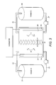
- FIG. 3 is a schematic view of a liquid/liquid regenerative fuel cell
- FIG. 4 is a schematic view of an assembled stack of a plurality of cells of the present invention.
- FIG. 5 is an exploded view of the assembled stack shown in FIG. 4 ;
- FIG. 6 is an exploded view of each of the individual cells present in the assembled stack shown in FIG. 4 ;
- FIG. 7 shows an I-V curve of a polysulphide-air alkaline regenerative fuel cell of the present invention.
- FIG. 8 shows a cyclic voltammogram for the redox couple [Cr(NH 3 ) 6 ] 3+ +e ⁇ [Cr(NH 3 ) 6 ] 2+ at pH 10, 0.1M NaNO 3 and 0.045M [Cr(NH 3 ) 6 ] 3+ using a glassy carbon electrode. Reversible peaks around 0.4V vs RHE ( ⁇ 0.2 vs SHE) are seen.
- FIG. 1 shows a schematic of a regenerative fuel cell in which the electrochemically active materials used to generate power are (a) a gas (supplied to the cathode) and (b) dissolved ions in a liquid anolyte (supplied to the anode).
- the liquid anolyte containing the electrochemically active species S 2 ⁇ is pumped from a compartment of an anolyte storage container ( 1 ), through a conduit ( 2 ) and into the anolyte compartment ( 3 ), where it is oxidised at an anode ( 4 ) according to the half reaction: S 2 ⁇ ⁇ S (sol) +2 e ⁇
- the anolyte containing the spent electrolyte species sulphur (S) is then carried away from the anolyte compartment through a second conduit ( 5 ) to the anolyte storage container ( 1 ), where it is stored in a compartment separate from the fresh anolyte compartment.
- the cathode and at least part of the catholyte compartment ( 8 ) are formed by a porous gas flow electrode and gaseous air (containing oxygen as the electrochemically active material) is pumped by an air compressor ( 6 ) through a conduit ( 7 ), to the cathode/cathode compartment ( 8 ), where the oxygen present in the air is reduced to hydroxide ions (OH ⁇ ) according to the half reaction: O 2 +4 e ⁇ +2H 2 O ⁇ 4OH ⁇ and the current is collected by a current collector ( 9 ).
- An alkaline membrane ( 10 ) separates the anolyte and catholyte compartments ( 3 & 8 ) and selectively passes the hydroxide ions from the catholyte to the anolyte side on the membrane ( 10 ) to balance the charge, thereby completing the electrical circuit.
- the oxygen depleted air is carried away from the catholyte compartment ( 8 ) by a second conduit ( 11 ) and discharged to the atmosphere.
- the system is reversed so that the electrochemically active species sulphur (S) is pumped from the anolyte storage container ( 1 ), through the conduit ( 5 ) to the anolyte compartment ( 3 ), where the spent electrolyte species S sol is reduced at the anode ( 4 ) to form the electrochemically active species S 2 ⁇ .
- the resulting regenerated electrolyte is transferred away from the anolyte container ( 3 ) by the pump, through the second conduit ( 2 ) to the anolyte storage container ( 1 ).
- hydroxide ions at the catholyte side of the alkaline membrane ( 10 ) are catalysed oxidised at the porous gas cathode ( 9 ) to water and oxygen (O 2 ); the oxygen is then transferred away from the porous cathode ( 8 ) through the conduit ( 11 ) and discharged into the atmosphere.
- FIG. 2 shows a schematic sectional view of a liquid/gas regenerative fuel cell similar to that set out in FIG. 1 but is less schematic in that it shows the anode and cathode compartments being narrower and shows the electrodes in the form of flow channel plates combined with current collectors.
- FIG. 3 shows a schematic of a regenerative fuel cell in which the electrochemically active materials supplied respectively to the anode and to the cathode are both dissolved in an aqueous liquid electrolyte.
- the liquid anolyte containing the electrochemically active species A (X+n) ⁇ (where A is the electrochemically active material supplied to the anode and (X+n) is the number of negative charges that A contains) is pumped from a compartment of an anolyte storage container ( 21 ), through a conduit ( 22 ) and into the anolyte compartment ( 23 ), where it is oxidised at the anode ( 24 ) according to the half reaction: A (X+n) ⁇ ⁇ A X +ne ⁇
- the anolyte containing the spent electrolyte species A X ⁇ is then carried away from the anolyte compartment through a second conduit ( 25 ) to the anolyte storage container ( 21 ), where it is stored in a compartment separate from the fresh anolyte compartment.
- the liquid catholyte containing the electrochemically active species C Y is pumped from a compartment of a catholyte storage container ( 26 ), through a conduit ( 27 ) and into the catholyte compartment ( 28 ), where it is reduced at the cathode ( 29 ) according to the half reaction: C Y +ne ⁇ ⁇ C (Y ⁇ n)
- the catholyte containing the spent catholyte species C (Y ⁇ n) is then carried away from the catholyte compartment through a second conduit ( 30 ) to the catholyte storage container ( 26 ), where it is stored in a compartment separate from the fresh catholyte compartment.
- the alkaline membrane ( 31 ) separating the anolyte and catholyte compartment ( 23 , 28 ) selectively passes hydroxide ions from the catholyte to the anolyte side of the membrane ( 11 ) to balance the charge and thereby completing the electrical circuit.
- the system is reversed so that the spent A X ⁇ is pumped from the anolyte storage container ( 21 ), through the conduit ( 25 ) to the anolyte compartment ( 23 ), where it is reduced at the anode ( 24 ) to the regenerated electrochemically active species A (X ⁇ n) ⁇ .
- the resulting regenerated electrolyte is transferred away from the anolyte container ( 23 ) by the pump through the conduit ( 22 ) to the anolyte storage container ( 21 ).
- spent C (Y ⁇ n) is pumped from the catholyte storage container ( 26 ), through the conduit ( 30 ) to the catholyte compartment ( 28 ), where it is oxidised at the cathode ( 29 ) to form electrochemically active species C Y .
- the resulting regenerated catholyte is transferred away from the catholyte compartment ( 28 ) by the pump through the conduit ( 27 ) to the catholyte storage container ( 26 ).
- liquid anolyte or catholyte alkaline redox couples mentioned above can be used in the set up shown in FIG. 3 .
- FIG. 4 shows a schematic of an assembled stack of a plurality of cells of the present invention.
- a single anode current collector and a single cathode collector are connected to the current collectors 24 , 29 of the individual cells.
- the stacking of cells and the feeding of electroactive species to the anode and to the cathode compartments is already well-known in the field of regenerative fuel cells and so further description will be omitted.
- FIG. 5 shows an exploded view of the assembled stack shown in FIG. 4 .
- One of the cells towards the centre of the stack is shown in exploded view, which is shown in further detail in FIG. 6 .
- FIG. 6 shows an exploded view of the components of a single cell present in the assembled stack shown in FIG. 4 .
- the flow channel plates are two-sided and each provides electrochemically active material to the two cells in the stack on either side of it; thus each plate has flow channels on both of its sides for providing electrochemically reactive material to a cathode located on the left hand side of the plate and different electrochemically reactive material to an anode located on the right hand side of the plate.
- a flow channel is provided on the other side of the same plate for providing electrochemically reactive material to an anode located on that side of the plate.
- the flow channels are serpentine in shape.
- a fluid (liquid or gas) that contains electrochemically reducible material enters the flow channel of the cathode side (I) of the plate (the left hand side of the right hand plate, as seen in FIG. 6 ) through a catholyte inlet (IV).
- a liquid anolyte containing an electrochemically oxidisable material enters an anolyte inlet (II) on the anode side of the flow channel plate (III) (the right hand side of the left hand plate as seen in FIG. 6 ) and passes via a separate flow channel into the anode compartment.
- the anolyte and the catholyte flow channels on the outsides of the two plates (as seen in FIG.
- the two fluids simultaneously diffuse through porous diffusion electrodes (VIII) where the electrochemically active species in the anolyte is oxidised and the electrochemically active species in the catholyte is reduced at catalytic layers adjacent to an anion exchange membrane (VII), thereby generating electrical current that passes through the current collectors ( 4 , 9 , 24 , 29 ) of the cells (see FIGS. 1 and 3 ).
- the spent fluids exit the flow channels through the anolyte outlet (V) and catholyte outlet (VI) respectively.
- Anions (which will generally be hydroxide ions) are transported though the membrane (IX) between the anode and cathode sides of the flow channel plates (I and III).
- the membrane itself is electrically insulating.
- the flexible sealing gaskets (VII) ensure hermetic sealing between the anolyte and catholyte sides of the flow channel plates (I and III) when the stack of cells is clamped together via the screws shown in FIGS. 4 and 5 .
- the direction of the flow of material in the plates is reversed.
- the electrochemically active species are regenerated by reduction and oxidation of the spent materials present in the anolyte and catholyte at the catalytic layers adjacent to the anion exchange membrane (IX) respectively.
- AAEM Alkaline Anion Exchange Membrane
- ARFC alkaline regenerative fuel cell
- the ARFC was built with standard fuel cell (FC) parts such as endplates, graphite flow channels, catalytic gas diffusion electrodes and an alkaline membrane with active area of 5 cm 2 .
- FC fuel cell
- Endplates and inlet/outlet hose barbs were made from plastic (specifically PVC) and are stable both in alkaline and polysulfide solutions.
- Gold coated current collector plates were introduced between endplates and graphite flow channel plates to collect the current.
- a membrane electrode assembly (MEA) comprising an alkaline membrane and platinum catalysed gas diffusion electrodes (Pt loading 1 mg/cm 2 , acquired from Electrochem Solutions Inc. of 10000 Wehrle Drive, Clarence N.Y. 14031, USA on both sides of the MEA, was used in the present example.
- This MEA was prepared in a similar way to an electron-beam-grafted ETFE alkaline anion-exchange membrane as used in the metal-cation-free solid-state alkaline fuel cells described by John R. Varcoe et al (Electrochemistry Communications; vol. 8 (2006) 839-843).
- the MEA was sandwiched between graphite flow channel plates.
- silicone gaskets were situated according to FIG. 6 .
- the polysulphide electrolyte was prepared by dissolving elemental sulphur in an aqueous sodium sulphide_solution; NaOH was added to adjust the pH.
- the total concentrations of the components in the mixture were: 3M NaOH, 1.5M Na 2 S and 3M of S.
- This alkaline (pH ⁇ 14) polysulphide solution was circulated through a filter (in order to prevent any insoluble substances from blocking the flow channels) to the anode side of the cell while air was pumped to the cathode side at constant flow rate in the range of 200-500 ml/min. This high rate was required to prevent catalyst poisoning at the cathode side.
- some of the ions of the redox couple present in the anolyte and/or catholyte may cross over the membrane which separates the anolyte compartment and the catholyte compartment into the catholyte and/or anolyte, respectively.
- This is called cross contamination and may cause a reduction in the overall operational efficiency of the regenerative fuel cell.
- contaminants may react with the electrode catalyst and consequently reduce the activity of the catalyst (known as “catalyst poisoning”).
- Improvements in both the selectivity of the anion exchange membrane (thereby reducing the amount of crossover contamination) and the resistance of the catalysts towards poisoning may increase the performance of the regenerative fuel cell.
Landscapes
- Life Sciences & Earth Sciences (AREA)
- Engineering & Computer Science (AREA)
- Manufacturing & Machinery (AREA)
- Sustainable Development (AREA)
- Sustainable Energy (AREA)
- Chemical & Material Sciences (AREA)
- Chemical Kinetics & Catalysis (AREA)
- Electrochemistry (AREA)
- General Chemical & Material Sciences (AREA)
- Fuel Cell (AREA)
- Inert Electrodes (AREA)
Abstract
Description
VIV (sol)+VIII (sol)
Br2+S2−
-
- a reversible anode in an anode compartment containing an anolyte;
- a reversible cathode in a cathode compartment containing a catholyte;
- an anionic membrane separating the anode compartment from the cathode compartment, which membrane is capable of selectively passing anions; and
- conduits configured, in said power delivery mode, for carrying electrochemically active species to the anode and to the cathode and, in a energy storage mode, for carrying generated electrochemically active species away from the anode and away from the cathode,
wherein the pH of the of the catholyte and the anolyte is at least 10, such as at least 12, for example at least 13.
O2+4e −+2H2O
[FeIII(CN)6]4− +e −
TeVIO4 2−+H2O+2e −
IVIIIO3 −+3H2O+6e −
PbIVO3 2−+2H2O+2e −
O2+4e −+2H2O
dehydroascorbate+2H2O+2e −
ethanal+2H2O+2e −
propanal+2H2O+2e −
glyoxal+2H2O+2e −
pyruvate+2H2O+2e −
2H2O+2e −
S(sol)+2e −
Se(sol)+2e −
2Te(sol)+2e −
SbVO3 −+H2O+2e −
FeIII-triethanolamine+e −
[CrIII(NH3)6]3+ +e −
[CrIII(picolinate)3]3+ +e −
[CrIII(picolinate)2(OH)]2 4++2e −
S(sol)+2e −
2S(sol)+4e −
O2+4e −+2H2O
2Se(sol)+4e −
O2+4e −+2H2O
4Te(sol)+4e −
O2+4e −+2H2O
[FeIII(CN)6]4− +e −
FeIII-triethanolamine+e −
2SbVO3 −+2H2O+4e −
O2+2H2O+4e −
PbIVO3 2−+2H2O+2e −
2H2O+2e −
2[FeIII(CN)6]4−+2e −
2H2O+2e −
TeVIO4 2−+H2O+2e −
2H2O+2e −
IVIIO3 −+3H2O+6e −
6H2O+6e −
O2+4e −+2H2O
the pH of the catholyte (and optionally the anolyte) is at least 13.
-
- a) in the cathode compartment during the course of the energy storage mode and
- b) in the anode compartment during the course of the power delivery mode
as hydroxide ions are consumed. The pH will generally rise: - c) in the in the cathode compartment during power delivery mode and
- d) in the anode compartment during the energy storage mode
as hydroxide ions are generated. Therefore, the pH in the cathode compartment should be in one or more of the above ranges: - i) at the end of, and preferably throughout, the power delivery mode, and
- ii) at the start of, and preferably throughout, the energy storage mode, and the pH in the in the anode compartment should be in one or more of the above ranges:
- iii) at the end of, and preferably throughout, the energy storage mode and
- iv) at the start of, and preferably throughout, the power delivery mode.
S2−→S(sol)+2e −
O2+4e −+2H2O→4OH−
and the current is collected by a current collector (9).
A(X+n)−→AX +ne −
CY +ne −→C(Y−n)
Claims (11)
2H2O+2e −
S(sol)+2e −
Se(sol)+2e −
2Te(sol)+2e −
SbVO3+2e −
FeIII-triethanolamine+e −
[Cr(NH3)6]3+ +e −
[CrIII-(picolinate)3]3+ +e −
[CrIII-(picolinate)2(OH)]2 4+ +e −
O2+4e −+2H2O
[FeIII(CN)6]4− +e −
TeVIO4 2−+H2O+2e −
IVIIO3 −+6H++6e −
PbIVO3 2−+3H++2e −
dehydroascorbate+2H2O+2e −
ethanal+2H2O+2e−
propanal+2H2O+2e −
glyoxal+2H2O+2e −
pyruvate+2H2O+2e −
2S(sol)+4e −
O2+4e −+2H2O
2Se(sol)+4e −
O2+2H2O+4e −
4Te(sol)+4e −
O2+2H2O+4e −
2SbVO3+2H2O+4e −
O2+2H2O+4e −
[FeIII(CN)6]4− +e −
FeIII-triethanolamine+e −
PbIVO2 −+3H2O+2e −
2H2O+2e −
2[FeIII(CN)6]4−+2e −
2H2O+2e −
TeVIO4 2−+H2O+2e −
2H2O+2e −
IVIIO3 −+3H2O+6e −
6H2O+6e −
O2+2H2O+4e −
Applications Claiming Priority (3)
| Application Number | Priority Date | Filing Date | Title |
|---|---|---|---|
| GB1015859.0 | 2010-09-21 | ||
| GBGB1015859.0A GB201015859D0 (en) | 2010-09-21 | 2010-09-21 | Regenerative fuel cells |
| PCT/EP2011/066238 WO2012038379A1 (en) | 2010-09-21 | 2011-09-19 | Regenerative fuel cells |
Publications (2)
| Publication Number | Publication Date |
|---|---|
| US20130330644A1 US20130330644A1 (en) | 2013-12-12 |
| US9843064B2 true US9843064B2 (en) | 2017-12-12 |
Family
ID=43065620
Family Applications (1)
| Application Number | Title | Priority Date | Filing Date |
|---|---|---|---|
| US13/825,199 Active 2033-09-25 US9843064B2 (en) | 2010-09-21 | 2011-09-19 | Regenerative fuel cells |
Country Status (5)
| Country | Link |
|---|---|
| US (1) | US9843064B2 (en) |
| EP (1) | EP2619835B1 (en) |
| JP (1) | JP5944906B2 (en) |
| GB (1) | GB201015859D0 (en) |
| WO (1) | WO2012038379A1 (en) |
Cited By (7)
| Publication number | Priority date | Publication date | Assignee | Title |
|---|---|---|---|---|
| US10992003B2 (en) | 2015-10-30 | 2021-04-27 | Massachusetts Institute Of Technology | Air-breathing aqueous sulfur rechargeable batteries |
| US11394035B2 (en) | 2017-04-06 | 2022-07-19 | Form Energy, Inc. | Refuelable battery for the electric grid and method of using thereof |
| US11552290B2 (en) | 2018-07-27 | 2023-01-10 | Form Energy, Inc. | Negative electrodes for electrochemical cells |
| US11611115B2 (en) | 2017-12-29 | 2023-03-21 | Form Energy, Inc. | Long life sealed alkaline secondary batteries |
| US11664547B2 (en) | 2016-07-22 | 2023-05-30 | Form Energy, Inc. | Moisture and carbon dioxide management system in electrochemical cells |
| US11949129B2 (en) | 2019-10-04 | 2024-04-02 | Form Energy, Inc. | Refuelable battery for the electric grid and method of using thereof |
| US11973254B2 (en) | 2018-06-29 | 2024-04-30 | Form Energy, Inc. | Aqueous polysulfide-based electrochemical cell |
Families Citing this family (4)
| Publication number | Priority date | Publication date | Assignee | Title |
|---|---|---|---|---|
| FR2989225A1 (en) * | 2012-04-10 | 2013-10-11 | Univ Rennes | CIRCULATING ELECTROLYTE FUEL CELL DEVICE PERCOLATING THROUGH ELECTRODES WITH A THREE DIMENSIONAL POROUS STRUCTURE |
| EP2997617B1 (en) * | 2013-05-16 | 2018-10-10 | United Technologies Corporation | Flow battery with hydrated ion-exchange membrane having maximum water domain cluster sizes |
| WO2015054260A2 (en) * | 2013-10-07 | 2015-04-16 | Board Of Regents, The University Of Texas System | A redox flow battery that uses complexes of cobalt and iron with amino-alcohol ligands in alkaline electrolytes to store electrical energy |
| US20220158212A1 (en) | 2020-11-16 | 2022-05-19 | Cougar Creek Technologies, Llc | Redox flow battery systems and methods utilizing a bipolar electrode structure |
Citations (11)
| Publication number | Priority date | Publication date | Assignee | Title |
|---|---|---|---|---|
| US3249522A (en) * | 1965-02-23 | 1966-05-03 | Socony Mobil Oil Co Inc | Electrochemical oxidation of hydrogen sulfide |
| US4485154A (en) | 1981-09-08 | 1984-11-27 | Institute Of Gas Technology | Electrically rechargeable anionically active reduction-oxidation electrical storage-supply system |
| US4784924A (en) * | 1981-06-08 | 1988-11-15 | University Of Akron | Metal-halogen energy storage device and system |
| US4786567A (en) | 1986-02-11 | 1988-11-22 | Unisearch Limited | All-vanadium redox battery |
| US5318865A (en) | 1991-06-06 | 1994-06-07 | Director-General, Agency Of Industrial Science And Technology | Redox battery |
| EP0664932B1 (en) | 1992-10-14 | 1998-01-14 | National Power Plc | Electrochemical apparatus for energy storage and/or power delivery comprising multi-compartment cells |
| EP1612874A1 (en) | 2004-07-02 | 2006-01-04 | SOLVAY (Société Anonyme) | Solid alkaline fuel cell comprising ion exchange membrane |
| US20090317668A1 (en) * | 2006-03-24 | 2009-12-24 | Acal Energy Limited | Fuel cells |
| US20100021778A1 (en) * | 2008-07-25 | 2010-01-28 | Lynntech, Inc. | Fuel cell emergency power system |
| US20100062313A1 (en) | 2007-01-26 | 2010-03-11 | Darren Jonathan Browning | Anion exchange membranes |
| US20110200848A1 (en) * | 2008-06-12 | 2011-08-18 | Massachusetts Institute Of Technology | High energy density redox flow device |
Family Cites Families (7)
| Publication number | Priority date | Publication date | Assignee | Title |
|---|---|---|---|---|
| JP2724817B2 (en) * | 1986-02-11 | 1998-03-09 | ユニサーチ・リミテッド | All Vanadium Redox Battery |
| WO1989006055A1 (en) * | 1987-12-14 | 1989-06-29 | Hughes Aircraft Company | Gas-permeable and ion-permeable membrane for electrochemical system |
| JPH01320776A (en) * | 1988-06-23 | 1989-12-26 | Nkk Corp | Redox flow type battery |
| JP3163370B2 (en) * | 1991-06-06 | 2001-05-08 | 経済産業省産業技術総合研究所長 | Redox battery |
| JPH08502387A (en) * | 1992-10-14 | 1996-03-12 | ナショナル パワー ピーエルシー | Electrochemical device for energy storage and power distribution using iron-sulfur couple |
| JP2000100460A (en) * | 1998-09-22 | 2000-04-07 | Sumitomo Electric Ind Ltd | All-iron battery and adjusting method for its charging depth |
| EP2254192A4 (en) * | 2008-02-18 | 2012-05-23 | Nat Inst Of Advanced Ind Scien | Air electrode |
-
2010
- 2010-09-21 GB GBGB1015859.0A patent/GB201015859D0/en not_active Ceased
-
2011
- 2011-09-19 EP EP11761328.1A patent/EP2619835B1/en active Active
- 2011-09-19 US US13/825,199 patent/US9843064B2/en active Active
- 2011-09-19 JP JP2013528705A patent/JP5944906B2/en active Active
- 2011-09-19 WO PCT/EP2011/066238 patent/WO2012038379A1/en active Application Filing
Patent Citations (11)
| Publication number | Priority date | Publication date | Assignee | Title |
|---|---|---|---|---|
| US3249522A (en) * | 1965-02-23 | 1966-05-03 | Socony Mobil Oil Co Inc | Electrochemical oxidation of hydrogen sulfide |
| US4784924A (en) * | 1981-06-08 | 1988-11-15 | University Of Akron | Metal-halogen energy storage device and system |
| US4485154A (en) | 1981-09-08 | 1984-11-27 | Institute Of Gas Technology | Electrically rechargeable anionically active reduction-oxidation electrical storage-supply system |
| US4786567A (en) | 1986-02-11 | 1988-11-22 | Unisearch Limited | All-vanadium redox battery |
| US5318865A (en) | 1991-06-06 | 1994-06-07 | Director-General, Agency Of Industrial Science And Technology | Redox battery |
| EP0664932B1 (en) | 1992-10-14 | 1998-01-14 | National Power Plc | Electrochemical apparatus for energy storage and/or power delivery comprising multi-compartment cells |
| EP1612874A1 (en) | 2004-07-02 | 2006-01-04 | SOLVAY (Société Anonyme) | Solid alkaline fuel cell comprising ion exchange membrane |
| US20090317668A1 (en) * | 2006-03-24 | 2009-12-24 | Acal Energy Limited | Fuel cells |
| US20100062313A1 (en) | 2007-01-26 | 2010-03-11 | Darren Jonathan Browning | Anion exchange membranes |
| US20110200848A1 (en) * | 2008-06-12 | 2011-08-18 | Massachusetts Institute Of Technology | High energy density redox flow device |
| US20100021778A1 (en) * | 2008-07-25 | 2010-01-28 | Lynntech, Inc. | Fuel cell emergency power system |
Non-Patent Citations (5)
| Title |
|---|
| Eh Yu et al., "Development of direct methanol alkaline fuel cells using anion exchange membranes," Journal of Power Sources, (2004), vol. 137, pp. 248-256. |
| International Search Report for PCT/EP2011/066238 dated Dec. 15, 2011. |
| JR Varcoe et al., "An electron-beam-grafted ETFE alkaline anion-exchange membrane in metal-cation-free solid-state alkaline fuel cells," Electrochemistry Communications, (2006), vol. 8(5), pp. 839-843. |
| JR Varcoe et al., "Poly(ethylene-co-tetrafluoroethylene)-Derived Radiation-Grafted Anion-Exchange Membrane with Properties Specifically Tailored for Application in Metal-Cation-Free Alkaline Polymer Electrolyte Fuel Cells," Chemistry of Materials, (2007), vol. 19, pp. 2686-2693. |
| Toshikatsu Sata. Ion Exchange Membranes. Preparation, Characterization, Modification and Application. (2004). The Royal Society of Chemistry. p. 174. * |
Cited By (7)
| Publication number | Priority date | Publication date | Assignee | Title |
|---|---|---|---|---|
| US10992003B2 (en) | 2015-10-30 | 2021-04-27 | Massachusetts Institute Of Technology | Air-breathing aqueous sulfur rechargeable batteries |
| US11664547B2 (en) | 2016-07-22 | 2023-05-30 | Form Energy, Inc. | Moisture and carbon dioxide management system in electrochemical cells |
| US11394035B2 (en) | 2017-04-06 | 2022-07-19 | Form Energy, Inc. | Refuelable battery for the electric grid and method of using thereof |
| US11611115B2 (en) | 2017-12-29 | 2023-03-21 | Form Energy, Inc. | Long life sealed alkaline secondary batteries |
| US11973254B2 (en) | 2018-06-29 | 2024-04-30 | Form Energy, Inc. | Aqueous polysulfide-based electrochemical cell |
| US11552290B2 (en) | 2018-07-27 | 2023-01-10 | Form Energy, Inc. | Negative electrodes for electrochemical cells |
| US11949129B2 (en) | 2019-10-04 | 2024-04-02 | Form Energy, Inc. | Refuelable battery for the electric grid and method of using thereof |
Also Published As
| Publication number | Publication date |
|---|---|
| EP2619835B1 (en) | 2017-06-14 |
| JP5944906B2 (en) | 2016-07-05 |
| GB201015859D0 (en) | 2010-10-27 |
| EP2619835A1 (en) | 2013-07-31 |
| JP2013541146A (en) | 2013-11-07 |
| WO2012038379A1 (en) | 2012-03-29 |
| US20130330644A1 (en) | 2013-12-12 |
Similar Documents
| Publication | Publication Date | Title |
|---|---|---|
| US9843064B2 (en) | Regenerative fuel cells | |
| US9559374B2 (en) | Electrochemical energy storage systems and methods featuring large negative half-cell potentials | |
| JP5231558B2 (en) | Fuel cell and cathode solution for fuel cell | |
| JP6549572B2 (en) | Redox flow battery and method for balancing the charge state of the flow battery | |
| CN107732272B (en) | Redox flow batteries comprising matched ionomer membranes | |
| US9899694B2 (en) | Electrochemical energy storage systems and methods featuring high open circuit potential | |
| US9391339B2 (en) | Regenerative fuel cells | |
| US10756377B2 (en) | Regenerative fuel cells | |
| EP3502057A1 (en) | Electrochemical energy storage systems and methods featuring optimal membrane systems | |
| EP2878021B1 (en) | Electrochemical systems featuring high open circuit potential | |
| JP7152032B2 (en) | Electrochemical cell and method of use | |
| US10424804B2 (en) | Optimization of the cerium-hydrogen redox flow cell | |
| US20220173422A1 (en) | Redox flow cell | |
| JP3163370B2 (en) | Redox battery | |
| EP2878020B1 (en) | Electrochemical energy storage systems and methods featuring large negative half-cell potentials | |
| US11705571B2 (en) | Foil-based redox flow battery | |
| US20230268540A1 (en) | All aqueous thermally-regenerative battery | |
| WO2023191716A2 (en) | A metal-feeding method for metal-air fuel cells |
Legal Events
| Date | Code | Title | Description |
|---|---|---|---|
| AS | Assignment |
Owner name: IMPERIAL INNOVATIONS LIMITED, UNITED KINGDOM Free format text: ASSIGNMENT OF ASSIGNORS INTEREST;ASSIGNORS:BRANDON, NIGEL;KUCERNAK, ANTHONY;YUFIT, VLADIMIR;SIGNING DATES FROM 20140429 TO 20140508;REEL/FRAME:032867/0480 |
|
| STCF | Information on status: patent grant |
Free format text: PATENTED CASE |
|
| AS | Assignment |
Owner name: IP2IPO INNOVATIONS LIMITED, ENGLAND Free format text: CHANGE OF NAME;ASSIGNOR:IMPERIAL INNOVATIONS LIMITED;REEL/FRAME:050403/0888 Effective date: 20190301 |
|
| MAFP | Maintenance fee payment |
Free format text: PAYMENT OF MAINTENANCE FEE, 4TH YEAR, LARGE ENTITY (ORIGINAL EVENT CODE: M1551); ENTITY STATUS OF PATENT OWNER: LARGE ENTITY Year of fee payment: 4 |