US9828971B2 - System and method for optimizing wind turbine operation - Google Patents
System and method for optimizing wind turbine operation Download PDFInfo
- Publication number
- US9828971B2 US9828971B2 US14/548,570 US201414548570A US9828971B2 US 9828971 B2 US9828971 B2 US 9828971B2 US 201414548570 A US201414548570 A US 201414548570A US 9828971 B2 US9828971 B2 US 9828971B2
- Authority
- US
- United States
- Prior art keywords
- voltage
- grid
- transformer
- wind turbine
- tap changer
- Prior art date
- Legal status (The legal status is an assumption and is not a legal conclusion. Google has not performed a legal analysis and makes no representation as to the accuracy of the status listed.)
- Active, expires
Links
- 238000000034 method Methods 0.000 title claims abstract description 49
- 238000004804 winding Methods 0.000 claims abstract description 72
- 230000008859 change Effects 0.000 claims description 13
- 238000012937 correction Methods 0.000 claims description 12
- 230000006698 induction Effects 0.000 claims description 4
- 230000004044 response Effects 0.000 claims description 4
- 230000009471 action Effects 0.000 abstract description 8
- 238000006243 chemical reaction Methods 0.000 description 28
- 230000006870 function Effects 0.000 description 14
- 238000004891 communication Methods 0.000 description 11
- 230000004224 protection Effects 0.000 description 7
- 230000005540 biological transmission Effects 0.000 description 4
- 239000003990 capacitor Substances 0.000 description 4
- 238000004364 calculation method Methods 0.000 description 3
- 238000010586 diagram Methods 0.000 description 3
- 230000001276 controlling effect Effects 0.000 description 2
- 238000013461 design Methods 0.000 description 2
- 238000005259 measurement Methods 0.000 description 2
- 230000000116 mitigating effect Effects 0.000 description 2
- 238000012986 modification Methods 0.000 description 2
- 230000004048 modification Effects 0.000 description 2
- 230000033228 biological regulation Effects 0.000 description 1
- 230000005465 channeling Effects 0.000 description 1
- 238000000605 extraction Methods 0.000 description 1
- 230000007246 mechanism Effects 0.000 description 1
- 230000008569 process Effects 0.000 description 1
- 230000001105 regulatory effect Effects 0.000 description 1
- 239000004065 semiconductor Substances 0.000 description 1
- 238000012546 transfer Methods 0.000 description 1
- 230000001052 transient effect Effects 0.000 description 1
Images


Classifications
-
- F—MECHANICAL ENGINEERING; LIGHTING; HEATING; WEAPONS; BLASTING
- F03—MACHINES OR ENGINES FOR LIQUIDS; WIND, SPRING, OR WEIGHT MOTORS; PRODUCING MECHANICAL POWER OR A REACTIVE PROPULSIVE THRUST, NOT OTHERWISE PROVIDED FOR
- F03D—WIND MOTORS
- F03D7/00—Controlling wind motors
- F03D7/02—Controlling wind motors the wind motors having rotation axis substantially parallel to the air flow entering the rotor
- F03D7/04—Automatic control; Regulation
- F03D7/042—Automatic control; Regulation by means of an electrical or electronic controller
-
- F03D9/003—
-
- F—MECHANICAL ENGINEERING; LIGHTING; HEATING; WEAPONS; BLASTING
- F03—MACHINES OR ENGINES FOR LIQUIDS; WIND, SPRING, OR WEIGHT MOTORS; PRODUCING MECHANICAL POWER OR A REACTIVE PROPULSIVE THRUST, NOT OTHERWISE PROVIDED FOR
- F03D—WIND MOTORS
- F03D7/00—Controlling wind motors
- F03D7/02—Controlling wind motors the wind motors having rotation axis substantially parallel to the air flow entering the rotor
- F03D7/0272—Controlling wind motors the wind motors having rotation axis substantially parallel to the air flow entering the rotor by measures acting on the electrical generator
-
- F—MECHANICAL ENGINEERING; LIGHTING; HEATING; WEAPONS; BLASTING
- F03—MACHINES OR ENGINES FOR LIQUIDS; WIND, SPRING, OR WEIGHT MOTORS; PRODUCING MECHANICAL POWER OR A REACTIVE PROPULSIVE THRUST, NOT OTHERWISE PROVIDED FOR
- F03D—WIND MOTORS
- F03D9/00—Adaptations of wind motors for special use; Combinations of wind motors with apparatus driven thereby; Wind motors specially adapted for installation in particular locations
- F03D9/20—Wind motors characterised by the driven apparatus
- F03D9/25—Wind motors characterised by the driven apparatus the apparatus being an electrical generator
- F03D9/255—Wind motors characterised by the driven apparatus the apparatus being an electrical generator connected to electrical distribution networks; Arrangements therefor
-
- H—ELECTRICITY
- H01—ELECTRIC ELEMENTS
- H01F—MAGNETS; INDUCTANCES; TRANSFORMERS; SELECTION OF MATERIALS FOR THEIR MAGNETIC PROPERTIES
- H01F29/00—Variable transformers or inductances not covered by group H01F21/00
- H01F29/02—Variable transformers or inductances not covered by group H01F21/00 with tappings on coil or winding; with provision for rearrangement or interconnection of windings
- H01F29/04—Variable transformers or inductances not covered by group H01F21/00 with tappings on coil or winding; with provision for rearrangement or interconnection of windings having provision for tap-changing without interrupting the load current
-
- H—ELECTRICITY
- H02—GENERATION; CONVERSION OR DISTRIBUTION OF ELECTRIC POWER
- H02P—CONTROL OR REGULATION OF ELECTRIC MOTORS, ELECTRIC GENERATORS OR DYNAMO-ELECTRIC CONVERTERS; CONTROLLING TRANSFORMERS, REACTORS OR CHOKE COILS
- H02P13/00—Arrangements for controlling transformers, reactors or choke coils, for the purpose of obtaining a desired output
- H02P13/06—Arrangements for controlling transformers, reactors or choke coils, for the purpose of obtaining a desired output by tap-changing; by rearranging interconnections of windings
-
- H—ELECTRICITY
- H02—GENERATION; CONVERSION OR DISTRIBUTION OF ELECTRIC POWER
- H02P—CONTROL OR REGULATION OF ELECTRIC MOTORS, ELECTRIC GENERATORS OR DYNAMO-ELECTRIC CONVERTERS; CONTROLLING TRANSFORMERS, REACTORS OR CHOKE COILS
- H02P9/00—Arrangements for controlling electric generators for the purpose of obtaining a desired output
- H02P9/007—Control circuits for doubly fed generators
-
- Y—GENERAL TAGGING OF NEW TECHNOLOGICAL DEVELOPMENTS; GENERAL TAGGING OF CROSS-SECTIONAL TECHNOLOGIES SPANNING OVER SEVERAL SECTIONS OF THE IPC; TECHNICAL SUBJECTS COVERED BY FORMER USPC CROSS-REFERENCE ART COLLECTIONS [XRACs] AND DIGESTS
- Y02—TECHNOLOGIES OR APPLICATIONS FOR MITIGATION OR ADAPTATION AGAINST CLIMATE CHANGE
- Y02E—REDUCTION OF GREENHOUSE GAS [GHG] EMISSIONS, RELATED TO ENERGY GENERATION, TRANSMISSION OR DISTRIBUTION
- Y02E10/00—Energy generation through renewable energy sources
- Y02E10/70—Wind energy
- Y02E10/72—Wind turbines with rotation axis in wind direction
-
- Y02E10/723—
-
- Y—GENERAL TAGGING OF NEW TECHNOLOGICAL DEVELOPMENTS; GENERAL TAGGING OF CROSS-SECTIONAL TECHNOLOGIES SPANNING OVER SEVERAL SECTIONS OF THE IPC; TECHNICAL SUBJECTS COVERED BY FORMER USPC CROSS-REFERENCE ART COLLECTIONS [XRACs] AND DIGESTS
- Y02—TECHNOLOGIES OR APPLICATIONS FOR MITIGATION OR ADAPTATION AGAINST CLIMATE CHANGE
- Y02E—REDUCTION OF GREENHOUSE GAS [GHG] EMISSIONS, RELATED TO ENERGY GENERATION, TRANSMISSION OR DISTRIBUTION
- Y02E10/00—Energy generation through renewable energy sources
- Y02E10/70—Wind energy
- Y02E10/76—Power conversion electric or electronic aspects
Definitions
- the present disclosure relates generally to wind turbines, and more particular to a system and method for optimizing wind turbine operation via a tap changer.
- Wind power is considered one of the cleanest, most environmentally friendly energy sources presently available, and wind turbines have gained increased attention in this regard.
- a modern wind turbine typically includes a tower, a generator, a gearbox, a nacelle, and a rotor having one or more rotor blades.
- the rotor blades transform wind energy into a mechanical rotational torque that drives one or more generators via the rotor.
- the generators are sometimes, but not always, rotationally coupled to the rotor through the gearbox.
- the gearbox steps up the inherently low rotational speed of the rotor for the generator to efficiently convert the rotational mechanical energy to electrical energy, which is fed into a utility grid via at least one electrical connection.
- Such configurations may also include power converters that are used to convert a frequency of generated electric power to a frequency substantially similar to a utility grid frequency.
- Renewable energy power systems typically includes a power converter with a regulated DC link controlled by a converter controller. More specifically, wind driven doubly-fed induction generator (DFIG) systems or full power conversion systems, typically include a power converter with an AC-DC-AC topology.
- DFIG doubly-fed induction generator
- AC-DC-AC topology For many wind turbines, the operating space, and hence value to the customer, is limited by maximum voltages for one or more wind turbine components inherent to DFIG systems.
- the wind turbine may be required to provide reactive power to the power grid, which may impose over-voltage conditions on secondary transformer windings where the power converter is connected. Thus, when the power converter provides reactive power, the resulting voltage may exceed a maximum specified continuous operating voltage level.
- the converter controller can shift the power factor away from the customer demanded set points; however, this is not always optimal. Further, such limitations tend to be more significant for DFIG generators that operate at a high rated slip (RPM) or for generators that are experiencing an over-speed condition.
- RPM high rated slip
- the art is continuously seeking new and improved system and methods for optimizing wind turbine operation for the customer while also maintaining voltage levels within specified operating limits. Accordingly, the present disclosure is directed to a system and method for optimizing wind turbine operation using a tap changer that allows the power grid to extract all available reactive power from the power converter without creating over-voltage conditions.
- the present disclosure is directed to a method for optimizing operation of a wind turbine.
- the method includes determining, via a converter controller of a power converter, a tap position for a tap changer configured between the power grid and a primary winding of the transformer. Another step of the method may also include calculating, via the converter controller, a primary voltage of the primary winding as a function of the tap position.
- the method also includes implementing, via the converter controller, a control action if the primary voltage or a measured secondary voltage of a secondary winding of the transformer is outside of a predetermined voltage range.
- the step of calculating the primary voltage of the primary winding as a function of the tap position further includes associating the tap position with a corresponding transformer ratio correction.
- the method may further include calculating the primary voltage of the primary winding as a function of the transformer ratio correction.
- the method further includes calculating the primary voltage as a function of one or more of the following: a secondary winding inductance, a converter inductance, one or more secondary winding currents, a primary winding inductance, a frequency, or a transformer impedance.
- the step of implementing the control action may include electrically disconnecting the wind turbine from the power grid. More specifically, in one embodiment, the step of electrically disconnecting the wind turbine from the power grid may include providing a disconnect device between the wind turbine and the power grid and an opening the disconnect device if the primary voltage or the secondary voltage is outside of the predetermined voltage range.
- the disconnect device may include a medium-voltage switch gear, a circuit breaker, a line contactor, a synchronizing switch, or any other suitable device.
- the tap changer may be an on-load tap changer.
- the wind turbine may include a wind-driven doubly-fed induction generator (DFIG).
- DFIG wind-driven doubly-fed induction generator
- the transformer may be a three-phase transformer or any other suitable transformer having any number of phases.
- the present disclosure is directed to a method for optimizing operation of a wind turbine.
- the method includes providing a tap changer between a power grid and a primary winding of the transformer.
- the method also includes changing a tap position of the tap changer so as to cause a change (e.g. a decrease) in a secondary voltage of a second winding of the transformer.
- Another step includes calculating, via a converter controller, the primary voltage of the primary winding as a function of the tap position.
- the method also includes controlling the wind turbine based on at least one of the primary voltage or the secondary voltage. It should be understood that the method may also include any of the additional features and/or steps as described herein in regards to the various embodiments.
- the step of controlling the wind turbine based on at least one of the primary voltage or the secondary voltage may include implementing, via the converter controller, a control action if the primary voltage or the secondary voltage exceeds a predetermined voltage threshold.
- the present disclosure is directed to a system for optimizing operation of a wind turbine.
- the system includes a tap changer operatively coupled between a power grid and a primary winding of a transformer connected to the power grid, and a controller communicatively coupled with the transformer and the tap changer.
- the tap changer via a tap controller or the converter controller, is configured to automatically change tap positions along the primary winding.
- the tap changer includes an individual controller that is configured to determine an appropriate tap position based on programmed settings and/or individual controller feedbacks.
- the tap changer may be configured to act upon transformer primary or secondary voltage feedbacks.
- the controller is configured to perform one or more operations.
- the one or more operations include: receiving a tap position from the tap changer, calculating a primary voltage of the primary winding as a function of the tap position or measuring a secondary voltage of the secondary winding, and implementing a control action if the primary voltage or secondary voltage is outside of a predetermined voltage range.
- the system may also include any of the additional features as described herein in regards to the various embodiments.
- FIG. 1 illustrates one embodiment of a wind turbine according to the present disclosure
- FIG. 2 illustrates one embodiment of an electrical and control system for a wind turbine according to the present disclosure
- FIG. 3 illustrates a block diagram of one embodiment of a controller suitable for use with the wind turbine as shown in FIG. 1 ;
- FIG. 4 illustrates one embodiment of a system for optimizing wind turbine operation according to the present disclosure
- FIG. 5 illustrates one embodiment of a graph of voltage versus time when the tap changer is in-active or absent according to the present disclosure
- FIG. 6 illustrates one embodiment of a graph of voltage versus time when the tap changer is active according to the present disclosure
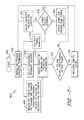
- FIG. 7 illustrates one embodiment of a flow diagram of a method for optimizing operation of a wind turbine according to the present disclosure.
- the present disclosure is directed to a system and method for optimizing wind turbine operation via a tap changer.
- the system includes a transformer having at least primary and secondary windings, a tap changer operatively coupled between a power grid and the primary winding of the transformer, and a converter controller communicatively coupled with the transformer and the tap changer.
- the tap changer may be an on-load tap changer that is configured to automatically change tap positions via an independent tap controller.
- the converter controller in response to a command to provide reactive power to the power grid, is configured to receive a tap position from the tap changer, calculate a primary voltage of the primary winding as a function of the tap position and/or measure a secondary voltage of the secondary winding, and implement a control action if the primary or secondary voltages is outside a predetermined voltage range, e.g. above an under-voltage threshold and below an over-voltage threshold.
- the tap changer of the present disclosure allows the power grid to extract all available reactive power without creating overvoltage conditions at the point of turbine connection, i.e. at the secondary winding.
- the converter controller monitors the calculated primary voltage and performs over-voltage protections accordingly.
- the tap changer and the effective-turns ratio that results from its operation regulate the secondary voltage in steady state conditions (and therefore protect the various wind turbine components).
- the converter controller ensures that the calculated primary voltage, in both steady and transient conditions, remains within safe limits by disconnecting the wind turbine from the power grid if primary voltage is outside of a predetermined voltage range.
- the present disclosure optimizes wind turbine operation at times when the power grid imposes demanding conditions that would otherwise be unobtainable due to voltage limitations of the turbine.
- FIG. 1 illustrates a perspective view of a portion of an exemplary wind turbine 100 according to the present disclosure.
- the wind turbine 100 includes a nacelle 102 housing a generator (not shown in FIG. 1 ).
- the nacelle 102 is mounted on a tower 104 (a portion of tower 104 being shown in FIG. 1 ).
- the tower 104 may have any suitable height that facilitates operation of wind turbine 100 as described herein.
- the wind turbine 100 also includes a rotor 106 that includes three rotor blades 108 attached to a rotatable hub 110 .
- the wind turbine 100 may include any number of rotor blades 108 to facilitate operation of the wind turbine 100 as described herein.
- the wind turbine 100 includes a gearbox (not shown in FIG. 1 ) operatively coupled to rotor 106 and a generator (not shown in FIG. 1 ).
- FIG. 2 illustrates a schematic view of one embodiment of an electrical and control system 200 that may be used with the wind turbine 100 .
- the rotor 106 includes rotor blades 108 coupled to the hub 110 .
- the rotor 106 also includes a low-speed shaft 112 rotatably coupled to the hub 110 .
- the low-speed shaft 112 is coupled to a gearbox 114 that is configured to step up the rotational speed of the low-speed shaft 112 and transfer that speed to a high-speed shaft 116 .
- the gearbox 114 may have any suitable step-up ratio that facilitates operation of wind turbine 100 as described herein.
- the wind turbine 100 may include a direct-drive generator that is rotatably coupled to rotor 106 without any intervening gearbox.
- the high-speed shaft 116 is rotatably coupled to the generator 118 .
- the generator 118 is may be a wound rotor, three-phase, double-fed induction (asynchronous) generator (DFIG) that includes a generator stator 120 magnetically coupled to a generator rotor 122 .
- DFIG three-phase, double-fed induction
- the generator rotor 122 may include a plurality of permanent magnets in place of rotor windings.
- the generator stator 120 may also be electrically coupled to a stator synchronizing switch 206 via a stator bus 208 .
- the generator rotor 122 is electrically coupled to a bi-directional power conversion assembly 210 via a rotor bus 212 .
- the generator rotor 122 may be electrically coupled to the rotor bus 212 via any other device that facilitates operation of the electrical and control system 200 as described herein.
- the electrical and control system 200 is configured as a full power conversion system (not shown) that includes a full power conversion assembly similar in design and operation to the power conversion assembly 210 and is electrically coupled to the generator stator 120 .
- the full power conversion assembly facilitates channeling electric power between the generator stator 120 and an electric power transmission and distribution grid (not shown).
- the stator bus 208 transmits three-phase power from the generator stator 120 to stator synchronizing switch 206 .
- the rotor bus 212 transmits three-phase power from the generator rotor 122 to the power conversion assembly 210 .
- the stator synchronizing switch 206 is electrically coupled to a main transformer circuit breaker 214 via a system bus 216 .
- one or more fuses are used instead of main transformer circuit breaker 214 .
- neither fuses nor main transformer circuit breaker 214 is used.
- the power conversion assembly 210 may include a rotor filter 218 that is electrically coupled to the generator rotor 122 via the rotor bus 212 .
- a rotor filter bus 219 electrically couples the rotor filter 218 to a rotor-side power converter 220 .
- the rotor-side power converter 220 is electrically coupled to a line-side power converter 222 .
- the rotor-side power converter 220 and line-side power converter 222 are power converter bridges including power semiconductors (not shown).
- the rotor-side power converter 220 and the line-side power converter 222 are configured in a three-phase, pulse width modulation (PWM) configuration including insulated gate bipolar transistor (IGBT) switching devices (not shown) that operate as known in the art.
- PWM pulse width modulation
- the rotor-side power converter 220 and the line-side power converter 222 can have any configuration using any switching devices that facilitate operation of electrical and control system 200 as described herein.
- the power conversion assembly 210 may also be in electronic data communication with the turbine controller 202 to control the operation of the rotor-side power converter 220 and the line-side power converter 222 .
- a line-side power converter bus 223 may electrically couple the line-side power converter 222 to a line filter 224 .
- a line bus 225 may electrically couple the line filter 224 to a line contactor 226 .
- the line contactor 226 may be electrically coupled to a conversion circuit breaker 228 via a conversion circuit breaker bus 230 .
- the conversion circuit breaker 228 may be electrically coupled to main transformer circuit breaker 214 via the system bus 216 and a connection bus 232 .
- the line filter 224 is electrically coupled to the system bus 216 directly via the connection bus 232 and includes any suitable protection scheme (not shown) configured to account for removal of the line contactor 226 and the conversion circuit breaker 228 from the electrical and control system 200 .
- the main transformer circuit breaker 214 may be electrically coupled to an electric power main transformer 234 via a generator-side bus 236 . Further, the main transformer 234 may be electrically coupled to a grid circuit breaker 238 via a breaker-side bus 240 .
- the grid circuit breaker 238 may be connected to the electric power transmission and distribution grid via a grid bus 242 .
- the three power lines or leads exiting the drawing area on the left of FIG. 2 can correspond to a three-phase power line as described herein.
- main transformer 234 may be electrically coupled to one or more fuses (not shown), rather than to grid circuit breaker 238 , via breaker-side bus 240 .
- fuses not shown
- main transformer 234 may be coupled to the electric power transmission and distribution grid via breaker-side bus 240 and grid bus 242 .
- the rotor-side power converter 220 is coupled in electrical communication with the line-side power converter 222 via a single direct current (DC) link 244 .
- the rotor-side power converter 220 and the line-side power converter 222 are electrically coupled via individual and separate DC links (not shown).
- the DC link 244 may include a positive rail 246 , a negative rail 248 , and at least one capacitor 250 coupled between the positive rail 246 and the negative rail 248 .
- the capacitor 250 may include one or more capacitors configured in series and/or in parallel between the positive rail 246 and the negative rail 248 .
- the electrical and control system 200 may also include a converter controller 262 and a higher-level turbine controller 202 .
- the controllers 202 , 262 may be configured to monitor and control at least some of the operational variables associated with wind turbine 100 .
- a first set of sensors 252 may be electrically coupled to each of the three phases of the grid bus 242 .
- the voltage and electric current sensors 252 may be electrically coupled to the system bus 216 .
- the voltage and electric current sensors 252 may be electrically coupled to any portion of the electrical and control system 200 that facilitates operation of the electrical and control system 200 as described herein.
- the controllers 202 , 262 are configured to receive any number of voltage and electric current measurement signals from any number of voltage and electric current sensors 252 .
- the converter controller 262 may receive voltage and electric current measurement signals from the first set of voltage and electric current sensors 252 , a second set of voltage and electric current sensors 254 coupled in electronic data communication with stator bus 208 , a third set of voltage and electric current sensors 256 coupled in electronic data communication with rotor bus 212 , and/or a fourth set of voltage and electric current sensors 264 coupled in electronic data communication with conversion circuit breaker bus 230 .
- the second set of voltage and electric current sensors 254 may be substantially similar to the first set of voltage and electric current sensors 252
- the fourth set of voltage and electric current sensors 264 may be substantially similar to the third set of voltage and electric current sensors 256 .
- the converter controller 262 may be substantially similar to the turbine controller 202 and may be in electronic data communication with the turbine controller 202 .
- the converter controller 262 may be physically integrated within the power conversion assembly 210 .
- the converter controller 262 may have any suitable configuration that facilitates operation of electrical and control system 200 as described herein.
- the converter controller 262 and/or the turbine controller 202 may include one or more processor(s) 176 and associated memory device(s) 178 configured to perform a variety of computer-implemented functions and/or instructions (e.g., performing the methods, steps, calculations and the like and storing relevant data as disclosed herein).
- the instructions when executed by the processor 176 can cause the processor 176 to perform operations, including providing control commands to the various components of the electrical and control system 200 .
- the controllers 202 , 262 may also include a communications module 180 to facilitate communications between the controllers 202 , 262 and the various components of the electrical and control system 200 , e.g. any of the components of FIG. 2 .
- the communications module 180 may include a sensor interface 182 (e.g., one or more analog-to-digital converters) to permit signals transmitted from one or more sensors 252 , 254 , 256 , 264 to be converted into signals that can be understood and processed by the processors 176 .
- a sensor interface 182 e.g., one or more analog-to-digital converters
- the sensors 252 , 254 , 256 , 264 may be communicatively coupled to the communications module 180 using any suitable means.
- the sensors 252 , 254 , 256 , 264 are coupled to the sensor interface 182 via a wired connection.
- the sensors 252 , 254 , 256 , 264 may be coupled to the sensor interface 182 via a wireless connection, such as by using any suitable wireless communications protocol known in the art.
- the processor 176 may be configured to receive one or more signals from the sensors.
- processor refers not only to integrated circuits referred to in the art as being included in a computer, but also refers to a controller, a microcontroller, a microcomputer, a programmable logic controller (PLC), an application specific integrated circuit, and other programmable circuits.
- the processor 176 is also configured to compute advanced control algorithms and communicate to a variety of Ethernet or serial-based protocols (Modbus, OPC, CAN, etc.).
- the memory device(s) 178 may generally comprise memory element(s) including, but not limited to, computer readable medium (e.g., random access memory (RAM)), computer readable non-volatile medium (e.g., a flash memory), a floppy disk, a compact disc-read only memory (CD-ROM), a magneto-optical disk (MOD), a digital versatile disc (DVD) and/or other suitable memory elements.
- RAM random access memory
- computer readable non-volatile medium e.g., a flash memory
- CD-ROM compact disc-read only memory
- MOD magneto-optical disk
- DVD digital versatile disc
- Such memory device(s) 178 may generally be configured to store suitable computer-readable instructions that, when implemented by the processor(s) 176 , configure the controller 202 to perform the various functions as described herein.
- the low-speed shaft 112 drives the gearbox 114 that subsequently steps up the low rotational speed of the low-speed shaft 112 to drive the high-speed shaft 116 at an increased rotational speed.
- the high speed shaft 116 rotatably drives the generator rotor 122 .
- a rotating magnetic field is induced by the generator rotor 122 and a voltage is induced within the generator stator 120 that is magnetically coupled to generator rotor 122 .
- the generator 118 converts the rotational mechanical energy to a sinusoidal, three-phase alternating current (AC) electrical energy signal in the generator stator 120 .
- the associated electrical power is transmitted to the main transformer 234 via the stator bus 208 , the stator synchronizing switch 206 , the system bus 216 , the main transformer circuit breaker 214 , and the generator-side bus 236 .
- the main transformer 234 steps up the voltage amplitude of the electrical power and the transformed electrical power is transmitted to a grid via breaker-side bus 240 , grid circuit breaker 238 , and the grid bus 242 .
- a second electrical power transmission path is also provided.
- electrical, three-phase, sinusoidal, AC power may be generated within the generator rotor 122 and may be transmitted to the power conversion assembly 210 via the rotor bus 212 .
- the electrical power may be transmitted to the rotor filter 218 such that the electrical power is modified for the rate of change of the PWM signals associated with the rotor-side power converter 220 .
- the rotor-side power converter 220 acts as a rectifier and rectifies the sinusoidal, three-phase AC power to DC power.
- the DC power is transmitted into the DC link 244 .
- the capacitor 250 facilitates mitigating the DC link 244 voltage amplitude variations by facilitating mitigation of a DC ripple associated with AC rectification.
- the DC power is subsequently transmitted from the DC link 244 to the line-side power converter 222 and the line-side power converter 222 acts as an inverter configured to convert the DC electrical power from the DC link 244 to three-phase, sinusoidal AC electrical power with pre-determined voltages, currents, and frequencies. This conversion is monitored and controlled via the converter controller 262 .
- the converted AC power is transmitted from the line-side power converter 222 to the system bus 216 via the line-side power converter bus 223 , the line bus 225 , the line contactor 226 , the conversion circuit breaker bus 230 , the conversion circuit breaker 228 , and the connection bus 232 .
- the line filter 224 compensates or adjusts for harmonic currents in the electric power transmitted from the line-side power converter 222 .
- the stator synchronizing switch 206 is configured to facilitate connecting the three-phase power from generator stator 120 with the three-phase power from power conversion assembly 210 .
- the conversion circuit breaker 228 , the main transformer circuit breaker 214 , and the grid circuit breaker 238 are configured to disconnect corresponding buses, for example, when excessive current flow may damage the components of electrical and control system 200 .
- Additional protection components may also be provided including line contactor 226 , which may be controlled to form a disconnect by opening a switch (not shown in FIG. 2 ) corresponding to each line of the line bus 225 .
- the system 275 may utilize existing components of the electrical and control system 200 .
- the system 275 may be integrated within the existing electrical and control system 200 .
- the system 275 includes the main transformer 234 and at least one tap changer 270 operatively coupled between the power grid 260 and the transformer 234 .
- the main transformer 234 may have any number of windings, including, for example, a primary winding 235 and one or more secondary windings 237 , 239 .
- the tap changer 270 may be operatively configured with the primary winding 235 of the transformer 234 on the power grid 260 side.
- a tap changer generally refers to a connection-point selection mechanism along a power transformer winding that allows a variable number of turns to be selected in discrete steps.
- a transformer having a variable-turns ratio can be produced, enabling stepped voltage regulation of the output.
- the tap changer 270 may be an on-load tap changer (OLTC).
- OLTC on-load tap changer
- the tap changer 270 may include a tap controller that is configured to automatically change tap positions while the tap changer is active.
- the tap changer may be manually operated to change tap positions.
- the converter controller 262 is configured to receive control signals from the turbine controller 202 .
- the turbine controller 202 will require the power conversion assembly 210 to provide a power level (e.g. reactive power) to the power grid 260 based on certain operating conditions.
- the control signals may be based on sensed conditions or operating characteristics of the wind turbine 100 and the electrical and control system 200 and/or one or more various grid conditions.
- the sensed conditions or operating characteristics are received by the turbine controller 202 and used to control operation of the power conversion assembly 210 via, for example, the converter controller 262 .
- the tap changer 270 may continuously send its tap position to the converter controller 262 .
- the tap changer 270 may change its tap position in response to reactive current (or grid voltage change or active current) that causes the transformer secondary voltage to change.
- the converter controller 262 can then use the tap position to calculate a primary voltage of the primary winding 235 .
- the converter controller 262 is configured to convert the tap position into a transformer ratio correction.
- the converter controller 262 may contain one or more look-up tables stored therein that contains all possible tap positions and corresponding transformer ratio corrections. As such, the converter controller 262 may receive the tap position and associate the tap position with a corresponding transformer ratio correction that may be used in the primary voltage calculation.
- the converter controller 262 may calculate the primary voltage of the primary winding 235 as a function of one or more of the following: a secondary winding inductance, a converter inductance, one or more secondary winding currents, a primary winding inductance, a frequency, or a transformer impedance. As shown in FIG. 4 , such operating parameters may be obtained via one or more additional current or voltage sensors 268 , 272 that may be added to the existing electrical and control system 200 or via one of the existing sensors 252 , 254 , 256 , 264 as described herein.
- the converter controller 262 may calculate the primary voltage of the primary winding 235 by calculating a voltage drop of the primary side using the current flowing through the primary side, the inductance of the primary winding 235 , and/or the frequency. Since the current flowing through the primary winding 235 is not typically directly measured, the converter controller 262 is configured to estimate the total current by adding the currents of all secondary windings 237 , 239 . Optionally, the converter controller 262 may also consider the voltage drop of one or more of the secondary winding 237 , 239 in the primary voltage calculation.
- the converter controller 262 calculates the voltage drop of one or more of the secondary windings 237 , 239 using the inductance of the secondary winding, the inductance of the power converter 210 , and the current flowing through the secondary windings 237 , 239 .
- the primary voltage may be calculated via the voltage drop of the primary side alone or in combination with the voltage drop of one or more of the secondary sides.
- the converter controller 262 calculates the primary voltage by converting (e.g. by multiplying or dividing) the voltage drop from the primary side (and optionally the secondary side) by the transformer ratio correction obtained from the tap position look-up table. The resulting conversion represents the calculated primary voltage of the primary winding 235 .
- the converter controller 262 continuously calculates the primary voltage while the tap changer 270 is enabled such that the controller 262 can ensure that the primary voltage is operating within safe limits, i.e. within a predetermined voltage range. If the calculated primary voltage remains within the predetermined voltage range, then the converter controller 262 continues to operate under normal operation. If, however, the calculated primary voltage is outside of the predetermined voltage range, then the converter controller 262 is configured to implement a control action. In addition, the converter controller 262 can continuously monitor the secondary voltage of the secondary windings 237 , 239 to ensure that the secondary voltages are operating within the predetermined voltage range.
- the wind turbine 100 may be electrically disconnected from the power grid 260 .
- the power converter 210 of the wind turbine 10 may be electrically disconnected from the secondary windings 237 , 239 of the transformer 234 , e.g. by opening line contactor 226 or conversion circuit breaker 228 .
- the system 275 may include a disconnect device, e.g. a medium-voltage switch gear (MVSG) 258 , communicatively coupled to the converter controller 262 and an optional protection relay 266 configured between the disconnect device and the power grid 260 .
- MVSG medium-voltage switch gear
- the MVSG 258 may be configured between the power grid 260 and the tap changer 270 such that when the primary voltage is outside of the predetermined voltage range, the converter controller 262 is configured to trip or open the disconnect device so as to electrically disconnect the system 275 from the power grid 260 .
- the MVSG 258 may be configured between the converter controller 262 and the main transformer 234 such that when the secondary voltage is outside of the predetermined voltage range, the converter controller 262 is configured to trip or open the disconnect device so as to electrically disconnect the system 275 from the power grid 260 .
- the disconnect device may include any other suitable device configured to electrically disconnect the system 275 from the power grid 260 so as to protect the turbine 100 from out-of-range voltage conditions.
- FIGS. 5 and 6 Various advantages of optimizing wind turbine operation according to the present disclosure are also illustrated in FIGS. 5 and 6 .
- a graph 300 of voltage versus time when the tap changer is in-active or absent is illustrated
- FIG. 6 illustrates a graph 350 of voltage versus time when the tap changer 270 is active.
- Each of the graphs 300 , 350 illustrate an under-voltage threshold 302 and over-voltage thresholds 304 , 354 , respectively.
- Such thresholds or protection settings may be customized in relation to grid codes and/or particular customer needs. Thus, the protection settings are typically equal to or lower than the capability curve or envelope enforced by the power conversion assembly 210 such that certain over-voltage conditions cannot occur.
- the under-voltage thresholds 302 are typically not affected by the OLTC function. Accordingly, when the OLTC function is active ( FIG. 6 ), the over-voltage threshold 354 may be increased by a certain factor to allow for higher voltages in the primary winding 235 (and therefore more extracted reactive power). Further, the over-voltage threshold 354 may be based on the calculated primary voltage when the OLTC function is active. Similarly, when the tap changer 270 is in-active, the over-voltage threshold 304 is typically based on the primary and/or secondary voltages.
- the secondary winding 239 voltage may be 1.09 pu (i.e. 9% above nominal) and the primary winding 235 voltage may be 1.11 pu as shown in the illustrated embodiment.
- the wind turbine 100 may be extracting rated active power, e.g. 2.7 MW, from the wind at a unity power factor, which translates into zero reactive power.
- the turbine controller 202 may then command the converter controller 262 to maintain power extraction at the current level while also providing 0.9 MVAR of reactive power.
- the secondary winding 239 voltage would normally have to increase, e.g. up to 1.12 pu (i.e.
- the tap changer 270 of the present disclosure assumes a tap position that reduces the secondary voltage by a certain amount, e.g. 1.08 pu.
- the primary voltage is larger than the original voltage amount as shown in FIG. 6 , e.g. from about 1.11 pu to about 1.2 pu, which is acceptable for the grid 260 and the primary winding 235 , yet the secondary voltage is within safe limits.
- the method 400 begins.
- the converter controller 262 samples and processes converter feedbacks.
- the converter controller 262 receives a tap position from the tap changer and computes the primary voltage of the transformer as a function of the feedbacks and the tap position.
- the converter controller 262 selects or determines secondary voltages of the transformer. Based on 406 and 408 , the converter controller 262 chooses the primary or secondary voltages per certain protection configurations at 414 .
- the converter controller 262 determines whether the chosen voltage is within a predetermined voltage range.
- the converter controller 262 implements a control action. For example, as mentioned, the converter controller 262 may send a trip signal to the line contactor 226 , the conversion circuit breaker 228 , or the grid disconnect device 258 .
- the converter controller 262 is also configured to calculate power quantities and at 416 , the converter controller 262 receives a power level request from the turbine controller 202 . As such, at 418 , the converter controller 262 determines whether the power request is satisfied. If not, the converter controller 262 adjusts converter voltages and currents at 412 . If yes, the method 400 continues again at 404 .
- Exemplary embodiments of a wind turbine, a control system for a wind turbine, and methods of optimizing operation of a wind turbine are described above in detail.
- the methods, wind turbine, and control system are not limited to the specific embodiments described herein, but rather, components of the wind turbine and/or the control system and/or steps of the methods may be utilized independently and separately from other components and/or steps described herein.
- the control system and methods may also be used in combination with other wind turbine power systems and methods, and are not limited to practice with only the power system as described herein. Rather, the exemplary embodiment can be implemented and utilized in connection with many other wind turbine or power system applications, such as solar power systems.
Landscapes
- Engineering & Computer Science (AREA)
- Power Engineering (AREA)
- Life Sciences & Earth Sciences (AREA)
- Sustainable Development (AREA)
- Sustainable Energy (AREA)
- Chemical & Material Sciences (AREA)
- Combustion & Propulsion (AREA)
- Mechanical Engineering (AREA)
- General Engineering & Computer Science (AREA)
- Control Of Eletrric Generators (AREA)
Abstract
Description
Claims (17)
Priority Applications (3)
| Application Number | Priority Date | Filing Date | Title |
|---|---|---|---|
| US14/548,570 US9828971B2 (en) | 2014-11-20 | 2014-11-20 | System and method for optimizing wind turbine operation |
| CA2912342A CA2912342C (en) | 2014-11-20 | 2015-11-19 | System and method for optimizing wind turbine operation |
| DE102015120126.7A DE102015120126A1 (en) | 2014-11-20 | 2015-11-20 | System and method for optimizing the operation of a wind turbine |
Applications Claiming Priority (1)
| Application Number | Priority Date | Filing Date | Title |
|---|---|---|---|
| US14/548,570 US9828971B2 (en) | 2014-11-20 | 2014-11-20 | System and method for optimizing wind turbine operation |
Publications (2)
| Publication Number | Publication Date |
|---|---|
| US20160146191A1 US20160146191A1 (en) | 2016-05-26 |
| US9828971B2 true US9828971B2 (en) | 2017-11-28 |
Family
ID=55914313
Family Applications (1)
| Application Number | Title | Priority Date | Filing Date |
|---|---|---|---|
| US14/548,570 Active 2035-02-15 US9828971B2 (en) | 2014-11-20 | 2014-11-20 | System and method for optimizing wind turbine operation |
Country Status (3)
| Country | Link |
|---|---|
| US (1) | US9828971B2 (en) |
| CA (1) | CA2912342C (en) |
| DE (1) | DE102015120126A1 (en) |
Cited By (2)
| Publication number | Priority date | Publication date | Assignee | Title |
|---|---|---|---|---|
| US10760547B2 (en) | 2018-12-18 | 2020-09-01 | General Electric Company | System and method for controlling voltage of a DC link of a power converter of an electrical power system |
| US10797486B2 (en) | 2018-12-18 | 2020-10-06 | General Electric Company | System and method for controlling DC link voltage of a power converter of an electrical power system |
Families Citing this family (15)
| Publication number | Priority date | Publication date | Assignee | Title |
|---|---|---|---|---|
| DE102014209332A1 (en) * | 2014-05-16 | 2015-11-19 | Senvion Gmbh | Wind turbine with improved overvoltage protection |
| US9494139B2 (en) * | 2014-07-31 | 2016-11-15 | General Electric Company | System and method for controlling a power output of a wind turbine generator |
| US10048709B2 (en) * | 2016-09-19 | 2018-08-14 | General Electric Company | System and method for regulation of voltage on an electric power system |
| EP3534479A4 (en) * | 2016-10-31 | 2019-10-30 | Mitsubishi Electric Corporation | Centralized voltage control device and centralized voltage control system |
| US10615608B2 (en) * | 2017-04-07 | 2020-04-07 | General Electric Company | Low-wind operation of clustered doubly fed induction generator wind turbines |
| CN108933500B (en) * | 2017-05-23 | 2020-06-02 | 东洋合成股份有限公司 | Wind power generation device capable of achieving low rotating speed and high electric energy |
| US10886726B2 (en) * | 2017-09-15 | 2021-01-05 | General Electric Company | Control method for protecting transformers |
| US10931177B2 (en) * | 2018-04-12 | 2021-02-23 | Yao-Lin Wang | Generator with built-in voltage controller inside a motor having a changeover knife switch configuration and loops |
| EP3591785A1 (en) | 2018-07-04 | 2020-01-08 | Vestas Wind Systems A/S | Wind turbine with an on-load tap changer configured with dynamic fault current injection |
| EP3591821B1 (en) | 2018-07-04 | 2023-06-07 | Vestas Wind Systems A/S | Controlled switching current of an on-load tap changer of a wind turbine |
| EP3742251A1 (en) * | 2019-05-24 | 2020-11-25 | Siemens Gamesa Renewable Energy Innovation & Technology, S.L. | Wind turbine transformer control |
| US20220294374A1 (en) * | 2019-08-15 | 2022-09-15 | EM-Energy Solutions AS | System and method for controlling a 3-phase transformer device |
| EP3866293A3 (en) * | 2020-01-21 | 2021-12-01 | Vestas Wind Systems A/S | Method of controlling a wind turbine |
| US11486360B2 (en) | 2020-04-10 | 2022-11-01 | General Electric Company | System and method for controlling wind turbine converters during high voltage ride through events |
| CN116227154B (en) * | 2023-01-09 | 2024-03-08 | 华能苏州热电有限责任公司 | Method for establishing high-low speed motor and variable frequency motor model under circulating pump working frequency |
Citations (18)
| Publication number | Priority date | Publication date | Assignee | Title |
|---|---|---|---|---|
| US6323618B1 (en) * | 2000-02-28 | 2001-11-27 | Mitsubishi Denki Kabushiki Kaisha | Excitation controller and excitation control method for stabilizing voltage in electric power system |
| US20040046530A1 (en) * | 2000-05-03 | 2004-03-11 | Peter Hessling | Power plant and a method for operation thereof |
| US20080093853A1 (en) * | 2006-10-20 | 2008-04-24 | Barker Sidney A | Method and apparatus for operating electrical machines |
| US20090096211A1 (en) * | 2005-05-13 | 2009-04-16 | Siemens Ag | Wind Farm and Method for Controlling the Same |
| US20090218817A1 (en) * | 2008-02-28 | 2009-09-03 | General Electric Company | Windfarm collector system loss optimization |
| US20100109447A1 (en) * | 2008-10-31 | 2010-05-06 | General Electric Company | Wide area transmission control of windfarms |
| US7989983B2 (en) * | 2009-11-24 | 2011-08-02 | American Superconductor Corporation | Power conversion systems |
| US8054652B2 (en) | 2007-07-16 | 2011-11-08 | Texas Instruments Incorporated | Systems and methods for off-time control in a voltage converter |
| US8121738B2 (en) * | 2010-08-26 | 2012-02-21 | General Electric Company | Method and apparatus for controlling wind turbine electric power generation |
| JP4894604B2 (en) | 2007-04-27 | 2012-03-14 | 富士電機株式会社 | Air-core type insulation transformer, signal transmission circuit and power conversion device using air-core type insulation transformer |
| US20120112713A1 (en) | 2009-04-16 | 2012-05-10 | Walter Kuehn | Method and apparatus for automatic network stabilization in electric power supply systems using at least one converter |
| US20120294045A1 (en) | 2011-05-19 | 2012-11-22 | Enphase Energy, Inc. | Method and apparatus for controlling resonant converter output power |
| US20130114312A1 (en) | 2011-11-04 | 2013-05-09 | Zbb Energy Corporation | System and Method for Power Conversion for Renewable Energy Sources |
| US20130116841A1 (en) * | 2010-06-30 | 2013-05-09 | Vestas Wind Systems A/S | Controlling a wind power plant transformer |
| US8570772B2 (en) | 2012-01-26 | 2013-10-29 | Linear Technology Corporation | Isolated flyback converter with efficient light load operation |
| US20130307494A1 (en) * | 2011-01-31 | 2013-11-21 | ALTOM Technology Ltd. | On-load tap-changer control method, excitation control system carrying out said control method and power excitation chain |
| US8610306B2 (en) * | 2011-07-29 | 2013-12-17 | General Electric Company | Power plant control system and method for influencing high voltage characteristics |
| US8698334B2 (en) * | 2009-04-17 | 2014-04-15 | Vestas Wind Systems A/S | Wind park, method of correcting voltage imbalances, and wind turbine |
-
2014
- 2014-11-20 US US14/548,570 patent/US9828971B2/en active Active
-
2015
- 2015-11-19 CA CA2912342A patent/CA2912342C/en active Active
- 2015-11-20 DE DE102015120126.7A patent/DE102015120126A1/en active Pending
Patent Citations (21)
| Publication number | Priority date | Publication date | Assignee | Title |
|---|---|---|---|---|
| US6323618B1 (en) * | 2000-02-28 | 2001-11-27 | Mitsubishi Denki Kabushiki Kaisha | Excitation controller and excitation control method for stabilizing voltage in electric power system |
| US20040046530A1 (en) * | 2000-05-03 | 2004-03-11 | Peter Hessling | Power plant and a method for operation thereof |
| US7808126B2 (en) | 2005-05-13 | 2010-10-05 | Siemens Aktiengesellschaft | Wind farm and method for controlling the same |
| US20090096211A1 (en) * | 2005-05-13 | 2009-04-16 | Siemens Ag | Wind Farm and Method for Controlling the Same |
| ES2428390T3 (en) | 2005-05-13 | 2013-11-07 | Siemens Aktiengesellschaft | Power control system of a wind farm |
| US20080093853A1 (en) * | 2006-10-20 | 2008-04-24 | Barker Sidney A | Method and apparatus for operating electrical machines |
| JP4894604B2 (en) | 2007-04-27 | 2012-03-14 | 富士電機株式会社 | Air-core type insulation transformer, signal transmission circuit and power conversion device using air-core type insulation transformer |
| US8054652B2 (en) | 2007-07-16 | 2011-11-08 | Texas Instruments Incorporated | Systems and methods for off-time control in a voltage converter |
| US20090218817A1 (en) * | 2008-02-28 | 2009-09-03 | General Electric Company | Windfarm collector system loss optimization |
| US7994658B2 (en) | 2008-02-28 | 2011-08-09 | General Electric Company | Windfarm collector system loss optimization |
| US20100109447A1 (en) * | 2008-10-31 | 2010-05-06 | General Electric Company | Wide area transmission control of windfarms |
| US20120112713A1 (en) | 2009-04-16 | 2012-05-10 | Walter Kuehn | Method and apparatus for automatic network stabilization in electric power supply systems using at least one converter |
| US8698334B2 (en) * | 2009-04-17 | 2014-04-15 | Vestas Wind Systems A/S | Wind park, method of correcting voltage imbalances, and wind turbine |
| US7989983B2 (en) * | 2009-11-24 | 2011-08-02 | American Superconductor Corporation | Power conversion systems |
| US20130116841A1 (en) * | 2010-06-30 | 2013-05-09 | Vestas Wind Systems A/S | Controlling a wind power plant transformer |
| US8121738B2 (en) * | 2010-08-26 | 2012-02-21 | General Electric Company | Method and apparatus for controlling wind turbine electric power generation |
| US20130307494A1 (en) * | 2011-01-31 | 2013-11-21 | ALTOM Technology Ltd. | On-load tap-changer control method, excitation control system carrying out said control method and power excitation chain |
| US20120294045A1 (en) | 2011-05-19 | 2012-11-22 | Enphase Energy, Inc. | Method and apparatus for controlling resonant converter output power |
| US8610306B2 (en) * | 2011-07-29 | 2013-12-17 | General Electric Company | Power plant control system and method for influencing high voltage characteristics |
| US20130114312A1 (en) | 2011-11-04 | 2013-05-09 | Zbb Energy Corporation | System and Method for Power Conversion for Renewable Energy Sources |
| US8570772B2 (en) | 2012-01-26 | 2013-10-29 | Linear Technology Corporation | Isolated flyback converter with efficient light load operation |
Cited By (2)
| Publication number | Priority date | Publication date | Assignee | Title |
|---|---|---|---|---|
| US10760547B2 (en) | 2018-12-18 | 2020-09-01 | General Electric Company | System and method for controlling voltage of a DC link of a power converter of an electrical power system |
| US10797486B2 (en) | 2018-12-18 | 2020-10-06 | General Electric Company | System and method for controlling DC link voltage of a power converter of an electrical power system |
Also Published As
| Publication number | Publication date |
|---|---|
| US20160146191A1 (en) | 2016-05-26 |
| CA2912342A1 (en) | 2016-05-20 |
| CA2912342C (en) | 2023-04-04 |
| DE102015120126A1 (en) | 2016-05-25 |
Similar Documents
| Publication | Publication Date | Title |
|---|---|---|
| CA2912342C (en) | System and method for optimizing wind turbine operation | |
| EP3189391B1 (en) | System and method for optimizing wind turbine operation | |
| EP3214719B1 (en) | System and method for controlling dc link voltage of a power converter for doubly-fed induction generators | |
| US9617976B2 (en) | Systems and methods for increasing wind turbine power output | |
| EP2323251B1 (en) | Method and apparatus for controlling a wind turbine | |
| US10396694B2 (en) | System and method for minimizing reactive current to limit rotor modulation index on a power converter | |
| US20160341179A1 (en) | Limit for derating scheme used in wind turbine control | |
| US9494139B2 (en) | System and method for controlling a power output of a wind turbine generator | |
| US10288040B2 (en) | Current limit calculation for wind turbine control | |
| EP3457417B1 (en) | Control method for protecting transformers | |
| US10218298B2 (en) | Spillover of reactive current to line side converter | |
| US20220263319A1 (en) | System and method for controlling low-speed operations of a wind turbine | |
| EP3456959B1 (en) | Control method for protecting primary windings of wind turbine transformers | |
| EP3410556A1 (en) | Control method for protecting generators | |
| US11879433B2 (en) | Method for operating a wind turbine, and a power plant | |
| US20220364544A1 (en) | Method for operating a wind turbine, and a power plant | |
| WO2024072367A1 (en) | System and method for reducing power changes on a drivetrain of a power generating asset during a grid event |
Legal Events
| Date | Code | Title | Description |
|---|---|---|---|
| AS | Assignment |
Owner name: GENERAL ELECTRIC COMPANY, NEW YORK Free format text: ASSIGNMENT OF ASSIGNORS INTEREST;ASSIGNORS:BERROTERAN GIL, IGOR;KLODOWSKI, ANTHONY MICHAEL;REEL/FRAME:034217/0843 Effective date: 20141119 Owner name: GE WIND ENERGY GMBH, GERMANY Free format text: ASSIGNMENT OF ASSIGNORS INTEREST;ASSIGNOR:BARTON, WERNER GERHARD;REEL/FRAME:034217/0940 Effective date: 20141120 |
|
| AS | Assignment |
Owner name: GENERAL ELECTRIC COMPANY, NEW YORK Free format text: ASSIGNMENT OF ASSIGNORS INTEREST;ASSIGNOR:GE WIND ENERGY GMBH;REEL/FRAME:034257/0854 Effective date: 20141121 |
|
| STCF | Information on status: patent grant |
Free format text: PATENTED CASE |
|
| MAFP | Maintenance fee payment |
Free format text: PAYMENT OF MAINTENANCE FEE, 4TH YEAR, LARGE ENTITY (ORIGINAL EVENT CODE: M1551); ENTITY STATUS OF PATENT OWNER: LARGE ENTITY Year of fee payment: 4 |
|
| AS | Assignment |
Owner name: GE INFRASTRUCTURE TECHNOLOGY LLC, SOUTH CAROLINA Free format text: ASSIGNMENT OF ASSIGNORS INTEREST;ASSIGNOR:GENERAL ELECTRIC COMPANY;REEL/FRAME:065727/0001 Effective date: 20231110 |