US9815183B2 - Quick detachable wrench structure - Google Patents
Quick detachable wrench structure Download PDFInfo
- Publication number
- US9815183B2 US9815183B2 US14/592,622 US201514592622A US9815183B2 US 9815183 B2 US9815183 B2 US 9815183B2 US 201514592622 A US201514592622 A US 201514592622A US 9815183 B2 US9815183 B2 US 9815183B2
- Authority
- US
- United States
- Prior art keywords
- accommodation room
- bottom plug
- quick detachable
- wrench structure
- disposed
- Prior art date
- Legal status (The legal status is an assumption and is not a legal conclusion. Google has not performed a legal analysis and makes no representation as to the accuracy of the status listed.)
- Active, expires
Links
Images


Classifications
-
- B—PERFORMING OPERATIONS; TRANSPORTING
- B25—HAND TOOLS; PORTABLE POWER-DRIVEN TOOLS; MANIPULATORS
- B25B—TOOLS OR BENCH DEVICES NOT OTHERWISE PROVIDED FOR, FOR FASTENING, CONNECTING, DISENGAGING OR HOLDING
- B25B23/00—Details of, or accessories for, spanners, wrenches, screwdrivers
- B25B23/0057—Socket or nut ejector means
-
- B—PERFORMING OPERATIONS; TRANSPORTING
- B25—HAND TOOLS; PORTABLE POWER-DRIVEN TOOLS; MANIPULATORS
- B25B—TOOLS OR BENCH DEVICES NOT OTHERWISE PROVIDED FOR, FOR FASTENING, CONNECTING, DISENGAGING OR HOLDING
- B25B13/00—Spanners; Wrenches
- B25B13/46—Spanners; Wrenches of the ratchet type, for providing a free return stroke of the handle
- B25B13/461—Spanners; Wrenches of the ratchet type, for providing a free return stroke of the handle with concentric driving and driven member
- B25B13/462—Spanners; Wrenches of the ratchet type, for providing a free return stroke of the handle with concentric driving and driven member the ratchet parts engaging in a direction radial to the tool operating axis
- B25B13/463—Spanners; Wrenches of the ratchet type, for providing a free return stroke of the handle with concentric driving and driven member the ratchet parts engaging in a direction radial to the tool operating axis a pawl engaging an externally toothed wheel
-
- B—PERFORMING OPERATIONS; TRANSPORTING
- B25—HAND TOOLS; PORTABLE POWER-DRIVEN TOOLS; MANIPULATORS
- B25B—TOOLS OR BENCH DEVICES NOT OTHERWISE PROVIDED FOR, FOR FASTENING, CONNECTING, DISENGAGING OR HOLDING
- B25B23/00—Details of, or accessories for, spanners, wrenches, screwdrivers
- B25B23/0007—Connections or joints between tool parts
- B25B23/0035—Connection means between socket or screwdriver bit and tool
Definitions
- the present invention generally relates to a wrench structure, more particularly to a wrench structure that can rapidly detach from a rotated piece after operations.
- FIG. 1 illustrates a wrench structure in prior arts.
- the wrench 90 has a wrench head portion 91 with an accommodation room 92 .
- An outer ring portion of the accommodation room 92 has a rotary device 93 .
- An inner surface of the rotary device 93 has a hole on a certain position thereof, and the hole has a spring (not shown in figure) and an urging member 931 , such as a steel ball. The urging member 931 is pushed to enter into the accommodation room 92 .
- the accommodation room 92 is able to accommodate a rotated piece 94 as nut, screw rod, etc.
- the accommodation room 92 and the rotated piece 94 are matched with each other.
- the rotated piece 94 has a positioning ring slot 941 , and the urging member 931 of the rotary device 93 is inwardly protruded to just fit into the positioning ring slot 941 in order to position the rotated piece 94 when the rotated piece 94 enters into the accommodation room 92 . Therefore, the rotated piece 94 may not slide from the accommodation room 92 , and can be tight or loose.
- the inventor has studied and developed a quick detachable wrench structure, which is able to conveniently, safely and rapidly detach a wrench from a rotated piece.
- the main objective of the present invention is to provide a quick detachable wrench structure, which is a simple structure and is able to rapidly detach a wrench from a rotated piece, such as nut, screw rod, etc. for operations with convenience and safety.
- the second objective of the present invention is to provide the quick detachable wrench structure, which has a pressing member with a function of automatic press-to-recover for following operations, so as to increase practicability and value-added.
- the quick detachable wrench structure comprises: a wrench head portion, which has a hollow operation accommodation room and a top end portion disposed at an upper portion thereof; and a pressing member, which has a top pressing portion and a bottom plug portion, the bottom plug portion is embedded in the operation accommodation room, the top pressing portion is disposed at an upper portion of the top end portion, a bottom edge of the bottom plug portion is propped against a bottom end of the top end portion in order to prevent the bottom plug portion from taking off from the operation accommodation room.
- peripheral walls of the operation accommodation room are selected from the group consisting of: curved surfaces, cambered surfaces and straight surfaces.
- the top end portion is circularly elongated to form a top protruding portion toward the center of the operation accommodation room, and the top protruding portion forms an urging ring space beyond the operation accommodation room.
- the pressing member has a central channel space.
- a bottom edge of the bottom plug portion is disposed at a positioning groove, a ring member is embedded in the positioning groove.
- the quick detachable wrench structure further comprises: a ratchet, which is disposed in the operation accommodation room and is a hollow ring member with an operation space, the ratchet has an outer ring teeth portion and an inner rotational surface that has a hole, wherein a spring and an urging member are in the hole; a reversing switch, which is disposed in a pivotal slot which is located at a rear end portion of the wrench head portion, and is connected with the ratchet for moving;
- the quick detachable wrench structure further comprises a flexible member between the top end portion and the top pressing portion.
- the flexible member has a through hole disposed in a central portion thereof and a protruding portion for a press-to-recover force.
- a bottom edge of the bottom plug portion is disposed one positioning hook or a plurality of positioning hooks averagely distributed on the bottom plug portion.
- the bottom plug portion has a plurality of vertical notches, and each of the notches cuts through the bottom plug portion and the positioning hook.
- the quick detachable wrench structure further comprises a press-to-position member, wherein the press-to-position member has a connecting part at an upper portion thereof and an urging part at a lower portion thereof, the connecting part is connected with the bottom plug portion, the urging part is propped against a bottom end of the top protruding portion or the top end portion.
- the connecting part and the bottom plug portion are connected with each other by means of snapping or screwing.
- FIG. 1 illustrates a schematic view of a wrench in prior arts
- FIG. 2 illustrates a schematic perspective view of a first preferred embodiment of the present invention
- FIG. 3 illustrates a schematic exploded view of the first preferred embodiment of the present invention
- FIG. 4 illustrates a schematic operation sectional view I of the first preferred embodiment of the present invention
- FIG. 4 a illustrates a schematic operation sectional view II of the first preferred embodiment of the present invention
- FIG. 5 illustrates a schematic view of another application of the first preferred embodiment of the present invention
- FIG. 6 illustrates a schematic operation sectional view I of the application of the first preferred embodiment of the present invention
- FIG. 6 a illustrates a schematic operation sectional view II of the application of the first preferred embodiment of the present invention
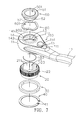
- FIG. 7 illustrates a schematic exploded view of a second preferred embodiment of the present invention.
- FIG. 8 illustrates a schematic exploded view of a third preferred embodiment of the present invention.
- FIG. 9 illustrates a schematic exploded view of a fourth preferred embodiment of the present invention.
- the quick detachable wrench structure 10 has: a wrench head portion 11 and a wrench handle 12 .
- the wrench head portion 11 has a hollow operation accommodation room 110 , and the peripheral walls of the operation accommodation room 110 are curved surfaces, cambered surfaces, straight surfaces, etc., but not limited thereto.
- the operation accommodation room 110 has a ring slot 13 at ex. a bottom edge thereof.
- a top end portion 14 is disposed at an upper portion of the wrench head portion 11 .
- the top end portion 14 is circularly elongated to form a top protruding portion 141 toward the center of the operation accommodation room 110 , and the top protruding portion 141 forms an urging ring space 142 beyond and internally elongated from the operation accommodation room 110 .
- the urging ring space 142 is an urging limit at an upper portion of the operation accommodation room 110 .
- the top end portion 14 is possibly a part of a top end of the wrench head portion 11 , that is, the wrench head portion 11 is elongated by integration to form the top protruding portion 141 and the urging ring space 142 .
- the first preferred embodiment of the present invention further comprises a pressing member 50 that is about a ring plug member.
- the pressing member 50 has a central channel space 501 , a top pressing portion 51 around the central channel space 501 and a bottom plug portion 52 .
- a bottom edge of the bottom plug portion 52 is disposed with a positioning groove 521 , a ring member 53 is embedded in the positioning groove 521 .
- the bottom plug portion 52 is inserted into the operation accommodation room 110 via the urging ring space 142 , the ring member 53 is embedded in the positioning groove 521 , so that the top pressing portion 51 goes beyond the top protruding portion 141 of the top end portion 14 .
- the bottom plug portion 52 is propped against the bottom end of the top protruding portion 141 of the top end portion 14 by means of the positioning groove 521 , so as to prevent the bottom plug portion 52 of the pressing member 50 from taking off upwardly.
- the pressing member 50 assembling to the quick detachable wrench structure 10 , to press the pressing member 50 is able to downwardly force a sleeve/screwed piece 100 disposed in the operation accommodation room 110 , so as to rapidly move the sleeve/screwed piece 100 out from the operation accommodation room 110 and detach the sleeve/screwed piece 100 from the quick detachable wrench structure 10 .
- the central channel space 501 serves as a positioning piece for screw rod to go through, the pressing member 50 may not have the central channel space 501 . Therefore, the central channel space 501 is unnecessary to the top pressing portion 51 or the bottom plug portion 52 . Obviously, it is easier to operate the pressing member 50 .
- the embodiment further comprises: a ratchet 20 , which is a hollow ring member with an operation space 21 , and has an outer ring teeth portion 22 and an inner rotational surface 211 , wherein the inner rotational surface 211 is a curved surface, a cambered surface, a straight surface, etc., but not limited thereto, the ratchet 20 is disposed in the operation accommodation room 110 of the wrench head portion 11 and has a hole 23 at a certain position of the inner rotational surface 211 , wherein the hole 23 has a spring 25 and an urging member 24 , wherein the urging member 24 can be a steel ball, and is urged by the spring 25 in order to extend into the operation accommodation room 100 , further, a pivotal slot 111 of the wrench head portion 11 is adjacent to the wrench handle 12 that is at a rear end portion of the wrench head portion 11 , a reversing switch 15 is disposed there as well,
- the operation accommodation room 110 of the wrench structure 10 firstly female-connects with a sleeve head portion 101 of the sleeve/screwed piece 100 , wherein the sleeve head portion 101 has a positioning ring slot 102 .
- the pressing member 50 is upwardly pushed.
- the inwardly protruding urging member 24 just embeds into the positioning ring slot 102 for positioning the sleeve head portion 101 .
- a screw rod 200 as positioning piece operates in order to female-connect the screw rod 200 with an accommodation portion 103 of the sleeve/screwed piece 100 .
- the top pressing portion 51 of the pressing member 50 is continuously pushed, and this makes that the bottom plug portion 52 of the pressing member 50 keeps thrusting the sleeve head portion 101 of the sleeve 100 . So that the positioning ring slot 102 is not propped against by the protruding urging member 24 . Accordingly, based on the pressing member 50 , the sleeve head portion 101 of the sleeve/screwed piece 100 moves a distance, as shown in FIG. 4 a . Hence, the sleeve head portion 101 of the sleeve/screwed piece 100 may not be restricted and automatically drop down because of gravity. As it can be seen, it is very convenient for taking the sleeve head portion 101 apart.
- FIG. 5 , FIG. 6 and FIG. 6 a illustrate a schematic view of another application of the first preferred embodiment of the present invention, a schematic operation sectional view I of the application of the first preferred embodiment of the present invention and a schematic operation sectional view II of the application of the first preferred embodiment of the present invention.
- the differences between the application shown in FIG. 5 , FIG. 6 and FIG. 6 a and the application shown in FIG. 4 and FIG. 4 a are described as follows.
- the wrench structure 10 directly screws the screw rod 200 (screwed piece/positioning piece). That is, a screw head 201 of the screw rod 200 is accommodated into the operation accommodation room 110 of the wrench structure 10 .
- the top pressing portion 51 of the pressing member 50 is continuously pushed, and this makes that the bottom plug portion 52 of the pressing member 50 keeps thrusting a screw head portion 201 of the screw rod 200 ; relatively, the wrench head portion 11 is withdrawn in order to release the wrench structure 10 or slightly loose the screw rod 200 , hence the wrench structure 10 is easily detached.
- FIG. 7 illustrates a second preferred embodiment of the quick detachable wrench structure of the present invention.
- the second preferred embodiment is a little different than the first preferred embodiment.
- the differences between the first and second preferred embodiment are described as follows.
- the second preferred embodiment further comprises a flexible member 60 , and the flexible member 60 is a spring piece or other patterns. More, the flexible member 60 has a through hole 601 disposed in a central portion thereof and a protruding portion 602 for a press-to-recover force.
- the flexible member 60 is disposed on the top protruding portion 141 of the top end portion 14 of the wrench head portion 11 according to the direction of figure; or the flexible member 60 is disposed a position beneath the top pressing portion 51 of the pressing member 50 , so that the flexible member 60 is between the top protruding portion 141 of the top end portion 14 of the wrench head portion 11 and the top pressing portion 51 of the pressing member 50 .
- the flexible member 60 is thrust by the pressing member 50 ; if the moment of the pressing member 50 is not working, a press-to-recover force from the flexible member 60 is able to urge the pressing member 50 up, so as to let the pressing member 50 be back to original status.
- FIG. 8 illustrates a third preferred embodiment of the quick detachable wrench structure of the present invention.
- the third preferred embodiment is a little different than the first preferred embodiment.
- the differences between the first and third preferred embodiment are described as follows.
- a bottom edge of the bottom plug portion 52 is disposed one positioning hook 522 or a plurality of positioning hooks 522 averagely distributed on the bottom plug portion 52 .
- the bottom plug portion 52 is instead of the positioning groove 521 and the ring member 53 .
- the bottom plug portion 52 has a plurality of vertical notches 54 (parallel to the central channel space 501 ), and each of the notches 54 downwardly cuts through the bottom plug portion 52 and the positioning hook 522 according to the direction of figure.
- the positioning hook 522 is against to the bottom end of the top protruding portion 141 in order to prevent that the bottom plug portion 52 of the pressing member 50 upwardly takes off. Squeeze forces from the notches 54 may stable the pressing member 50 .
- FIG. 9 illustrates a fourth preferred embodiment of the quick detachable wrench structure of the present invention.
- the third preferred embodiment is a little different than the first preferred embodiment. The differences between the first and third preferred embodiment are described as follows.
- the bottom of the pressing member 50 is connected with a press-to-position member 55 , which has a connecting part 551 at an upper portion thereof and an urging part 552 at a lower portion thereof.
- the press-to-position member 55 When in assembly, the press-to-position member 55 upwardly enters into the operation accommodation room 110 , so as to integrate the connecting part 551 and the bottom plug portion 52 , and therefore the urging part 552 is against to the bottom end of the top protruding portion 141 of the top end portion 14 in order to prevent that the bottom plug portion 52 of the pressing member 50 takes off upwardly.
- the fourth preferred embodiment adopts the press-to-position member 55 to replace the positioning groove 521 and the ring member 53 in FIG. 3 . More, the connecting part 551 and the bottom plug portion 52 are connected with each other by means of snap or screwing for more stability.
- the quick detachable wrench structure is able to rapidly detach a wrench from a rotated piece as bolt, nut, etc., so as to create convenience and safety.
- Another value-added is that the pressing member is with the advantage of press-to-recover for following operations.
Landscapes
- Engineering & Computer Science (AREA)
- Mechanical Engineering (AREA)
- Details Of Spanners, Wrenches, And Screw Drivers And Accessories (AREA)
Abstract
A quick detachable wrench structure comprises: a wrench head portion, which has a hollow operation accommodation room and a top end portion disposed at an upper portion thereof; and a pressing member, which has a top pressing portion and a bottom plug portion, the bottom plug portion is embedded in the operation accommodation room, the top pressing portion is disposed at an upper portion of the top end portion, a bottom edge of the bottom plug portion is against to a bottom end of the top end portion in order to avoid the bottom plug portion taking off from the operation accommodation room.
Description
1. Field of the Invention
The present invention generally relates to a wrench structure, more particularly to a wrench structure that can rapidly detach from a rotated piece after operations.
2. Description of the Prior Art
Wrench is a regular tool for fastening or loosing working parts, such as bolt, nut, etc. There are many kinds of wrenches, which has open-end wrench, combination wrench, wrench, adjustable wrench, socket wrench, etc. Please refer to FIG. 1 , which illustrates a wrench structure in prior arts. The wrench 90 has a wrench head portion 91 with an accommodation room 92. An outer ring portion of the accommodation room 92 has a rotary device 93. An inner surface of the rotary device 93 has a hole on a certain position thereof, and the hole has a spring (not shown in figure) and an urging member 931, such as a steel ball. The urging member 931 is pushed to enter into the accommodation room 92. The accommodation room 92 is able to accommodate a rotated piece 94 as nut, screw rod, etc. The accommodation room 92 and the rotated piece 94 are matched with each other. The rotated piece 94 has a positioning ring slot 941, and the urging member 931 of the rotary device 93 is inwardly protruded to just fit into the positioning ring slot 941 in order to position the rotated piece 94 when the rotated piece 94 enters into the accommodation room 92. Therefore, the rotated piece 94 may not slide from the accommodation room 92, and can be tight or loose. Traditionally, there still exists a disadvantage, for example, when the rotated piece 94 drops out from the accommodation room 92 of the wrench 90, and the rotated piece 94 and the accommodation room 92 are tightened hardly to each other, hence finger is always used to downwardly push the rotated piece 94 in the accommodation room 92 out. Obviously, it is inconvenient to detach the rotated piece 94 from the wrench 90. As it can be seen, to solve the problem of inconvenient detaching process is an important issue for people who is skillful in the art.
Accordingly, the inventor has studied and developed a quick detachable wrench structure, which is able to conveniently, safely and rapidly detach a wrench from a rotated piece.
The main objective of the present invention is to provide a quick detachable wrench structure, which is a simple structure and is able to rapidly detach a wrench from a rotated piece, such as nut, screw rod, etc. for operations with convenience and safety.
The second objective of the present invention is to provide the quick detachable wrench structure, which has a pressing member with a function of automatic press-to-recover for following operations, so as to increase practicability and value-added.
To approach aforesaid objectives, the quick detachable wrench structure comprises: a wrench head portion, which has a hollow operation accommodation room and a top end portion disposed at an upper portion thereof; and a pressing member, which has a top pressing portion and a bottom plug portion, the bottom plug portion is embedded in the operation accommodation room, the top pressing portion is disposed at an upper portion of the top end portion, a bottom edge of the bottom plug portion is propped against a bottom end of the top end portion in order to prevent the bottom plug portion from taking off from the operation accommodation room.
Accordingly, the peripheral walls of the operation accommodation room are selected from the group consisting of: curved surfaces, cambered surfaces and straight surfaces.
Accordingly, the top end portion is circularly elongated to form a top protruding portion toward the center of the operation accommodation room, and the top protruding portion forms an urging ring space beyond the operation accommodation room.
Accordingly, the pressing member has a central channel space.
Accordingly, a bottom edge of the bottom plug portion is disposed at a positioning groove, a ring member is embedded in the positioning groove.
Accordingly, the quick detachable wrench structure further comprises: a ratchet, which is disposed in the operation accommodation room and is a hollow ring member with an operation space, the ratchet has an outer ring teeth portion and an inner rotational surface that has a hole, wherein a spring and an urging member are in the hole; a reversing switch, which is disposed in a pivotal slot which is located at a rear end portion of the wrench head portion, and is connected with the ratchet for moving;
- a support ring member, which is disposed in the operation accommodation room and is female-connected with a lower portion of the ring teeth portion of the ratchet, so as to support the ratchet; and
- a positioning member, which is embedded in a ring slot where is at a lower portion of the operation accommodation room so as to urge the support ring member, and is a positioning stop for the entire operation accommodation room.
Accordingly, the quick detachable wrench structure further comprises a flexible member between the top end portion and the top pressing portion.
Accordingly, the flexible member has a through hole disposed in a central portion thereof and a protruding portion for a press-to-recover force.
Accordingly, a bottom edge of the bottom plug portion is disposed one positioning hook or a plurality of positioning hooks averagely distributed on the bottom plug portion.
Accordingly, the bottom plug portion has a plurality of vertical notches, and each of the notches cuts through the bottom plug portion and the positioning hook.
Accordingly, the quick detachable wrench structure further comprises a press-to-position member, wherein the press-to-position member has a connecting part at an upper portion thereof and an urging part at a lower portion thereof, the connecting part is connected with the bottom plug portion, the urging part is propped against a bottom end of the top protruding portion or the top end portion.
Accordingly, the connecting part and the bottom plug portion are connected with each other by means of snapping or screwing.
The objectives, spirits, and advantages of the preferred embodiments of the present invention will be readily understood by the accompanying drawings and detailed descriptions, wherein:
Following preferred embodiments and figures will be described in detail so as to achieve aforesaid objectives.
Please refer to FIG. 2 and FIG. 3 , which illustrate a first preferred embodiment of the quick detachable wrench structure of the present invention. As shown in the figures, the quick detachable wrench structure 10 has: a wrench head portion 11 and a wrench handle 12. The wrench head portion 11 has a hollow operation accommodation room 110, and the peripheral walls of the operation accommodation room 110 are curved surfaces, cambered surfaces, straight surfaces, etc., but not limited thereto. The operation accommodation room 110 has a ring slot 13 at ex. a bottom edge thereof. A top end portion 14 is disposed at an upper portion of the wrench head portion 11. The top end portion 14 is circularly elongated to form a top protruding portion 141 toward the center of the operation accommodation room 110, and the top protruding portion 141 forms an urging ring space 142 beyond and internally elongated from the operation accommodation room 110. The urging ring space 142 is an urging limit at an upper portion of the operation accommodation room 110. The top end portion 14 is possibly a part of a top end of the wrench head portion 11, that is, the wrench head portion 11 is elongated by integration to form the top protruding portion 141 and the urging ring space 142.
The first preferred embodiment of the present invention further comprises a pressing member 50 that is about a ring plug member. The pressing member 50 has a central channel space 501, a top pressing portion 51 around the central channel space 501 and a bottom plug portion 52. A bottom edge of the bottom plug portion 52 is disposed with a positioning groove 521, a ring member 53 is embedded in the positioning groove 521. Please refer to FIG. 4 simultaneously, for assembling the pressing member 50, the bottom plug portion 52 is inserted into the operation accommodation room 110 via the urging ring space 142, the ring member 53 is embedded in the positioning groove 521, so that the top pressing portion 51 goes beyond the top protruding portion 141 of the top end portion 14. The bottom plug portion 52 is propped against the bottom end of the top protruding portion 141 of the top end portion 14 by means of the positioning groove 521, so as to prevent the bottom plug portion 52 of the pressing member 50 from taking off upwardly.
For the pressing member 50 assembling to the quick detachable wrench structure 10, to press the pressing member 50 is able to downwardly force a sleeve/screwed piece 100 disposed in the operation accommodation room 110, so as to rapidly move the sleeve/screwed piece 100 out from the operation accommodation room 110 and detach the sleeve/screwed piece 100 from the quick detachable wrench structure 10. Since the central channel space 501 serves as a positioning piece for screw rod to go through, the pressing member 50 may not have the central channel space 501. Therefore, the central channel space 501 is unnecessary to the top pressing portion 51 or the bottom plug portion 52. Obviously, it is easier to operate the pressing member 50.
Further, as shown in figure, the present embodiment is described according to a ratchet wrench structure. The embodiment further comprises: a ratchet 20, which is a hollow ring member with an operation space 21, and has an outer ring teeth portion 22 and an inner rotational surface 211, wherein the inner rotational surface 211 is a curved surface, a cambered surface, a straight surface, etc., but not limited thereto, the ratchet 20 is disposed in the operation accommodation room 110 of the wrench head portion 11 and has a hole 23 at a certain position of the inner rotational surface 211, wherein the hole 23 has a spring 25 and an urging member 24, wherein the urging member 24 can be a steel ball, and is urged by the spring 25 in order to extend into the operation accommodation room 100, further, a pivotal slot 111 of the wrench head portion 11 is adjacent to the wrench handle 12 that is at a rear end portion of the wrench head portion 11, a reversing switch 15 is disposed there as well, wherein a wrench member 151 is disposed on the reversing switch 15, and the reversing switch 15 is connected with the ratchet 20 for moving; a support ring member 30, which is disposed in the operation accommodation room 110 and is female-connected with a lower portion of the ring teeth portion 22 of the ratchet 20, so as to support the ratchet 20; a positioning member 40, which is a C-typed member and is embedded in a ring slot 13 which is located at a lower portion of the operation accommodation room 110 so as to urge the support ring member 30, and is a positioning stop for the entire operation accommodation room 110; each of two ring ends of the positioning member 40 has a through hole 41 in order to be convenient for positioning and moving operations.
Please refer to FIG. 2 , FIG. 4 and FIG. 4a . In order to operate the quick detachable wrench structure, the operation accommodation room 110 of the wrench structure 10 firstly female-connects with a sleeve head portion 101 of the sleeve/screwed piece 100, wherein the sleeve head portion 101 has a positioning ring slot 102. Secondly, the pressing member 50 is upwardly pushed. The inwardly protruding urging member 24 just embeds into the positioning ring slot 102 for positioning the sleeve head portion 101. Continuously, a screw rod 200 as positioning piece operates in order to female-connect the screw rod 200 with an accommodation portion 103 of the sleeve/screwed piece 100.
Further, the top pressing portion 51 of the pressing member 50 is continuously pushed, and this makes that the bottom plug portion 52 of the pressing member 50 keeps thrusting the sleeve head portion 101 of the sleeve 100. So that the positioning ring slot 102 is not propped against by the protruding urging member 24. Accordingly, based on the pressing member 50, the sleeve head portion 101 of the sleeve/screwed piece 100 moves a distance, as shown in FIG. 4a . Hence, the sleeve head portion 101 of the sleeve/screwed piece 100 may not be restricted and automatically drop down because of gravity. As it can be seen, it is very convenient for taking the sleeve head portion 101 apart.
Please refer to FIG. 5 , FIG. 6 and FIG. 6a , which illustrate a schematic view of another application of the first preferred embodiment of the present invention, a schematic operation sectional view I of the application of the first preferred embodiment of the present invention and a schematic operation sectional view II of the application of the first preferred embodiment of the present invention. The differences between the application shown in FIG. 5 , FIG. 6 and FIG. 6a and the application shown in FIG. 4 and FIG. 4a are described as follows. The wrench structure 10 directly screws the screw rod 200 (screwed piece/positioning piece). That is, a screw head 201 of the screw rod 200 is accommodated into the operation accommodation room 110 of the wrench structure 10. Continuously, the top pressing portion 51 of the pressing member 50 is continuously pushed, and this makes that the bottom plug portion 52 of the pressing member 50 keeps thrusting a screw head portion 201 of the screw rod 200; relatively, the wrench head portion 11 is withdrawn in order to release the wrench structure 10 or slightly loose the screw rod 200, hence the wrench structure 10 is easily detached.
Please refer to FIG. 7 , which illustrates a second preferred embodiment of the quick detachable wrench structure of the present invention. The second preferred embodiment is a little different than the first preferred embodiment. The differences between the first and second preferred embodiment are described as follows. The second preferred embodiment further comprises a flexible member 60, and the flexible member 60 is a spring piece or other patterns. More, the flexible member 60 has a through hole 601 disposed in a central portion thereof and a protruding portion 602 for a press-to-recover force. The flexible member 60 is disposed on the top protruding portion 141 of the top end portion 14 of the wrench head portion 11 according to the direction of figure; or the flexible member 60 is disposed a position beneath the top pressing portion 51 of the pressing member 50, so that the flexible member 60 is between the top protruding portion 141 of the top end portion 14 of the wrench head portion 11 and the top pressing portion 51 of the pressing member 50. When the top pressing portion 51 of the pressing member 50 pressing a rotated piece (or a positioned piece), the flexible member 60 is thrust by the pressing member 50; if the moment of the pressing member 50 is not working, a press-to-recover force from the flexible member 60 is able to urge the pressing member 50 up, so as to let the pressing member 50 be back to original status.
Please refer to FIG. 8 , which illustrates a third preferred embodiment of the quick detachable wrench structure of the present invention. The third preferred embodiment is a little different than the first preferred embodiment. The differences between the first and third preferred embodiment are described as follows. A bottom edge of the bottom plug portion 52 is disposed one positioning hook 522 or a plurality of positioning hooks 522 averagely distributed on the bottom plug portion 52. The bottom plug portion 52 is instead of the positioning groove 521 and the ring member 53. The bottom plug portion 52 has a plurality of vertical notches 54 (parallel to the central channel space 501), and each of the notches 54 downwardly cuts through the bottom plug portion 52 and the positioning hook 522 according to the direction of figure. So that the plurality of the bottom plug portion 52 and the positioning hook 522 are circularly distributed. When the pressing member 50 is assembled into the operation accommodation room 110, the positioning hook 522 is against to the bottom end of the top protruding portion 141 in order to prevent that the bottom plug portion 52 of the pressing member 50 upwardly takes off. Squeeze forces from the notches 54 may stable the pressing member 50.
Please refer to FIG. 9 , which illustrates a fourth preferred embodiment of the quick detachable wrench structure of the present invention. The third preferred embodiment is a little different than the first preferred embodiment. The differences between the first and third preferred embodiment are described as follows. The bottom of the pressing member 50 is connected with a press-to-position member 55, which has a connecting part 551 at an upper portion thereof and an urging part 552 at a lower portion thereof. When in assembly, the press-to-position member 55 upwardly enters into the operation accommodation room 110, so as to integrate the connecting part 551 and the bottom plug portion 52, and therefore the urging part 552 is against to the bottom end of the top protruding portion 141 of the top end portion 14 in order to prevent that the bottom plug portion 52 of the pressing member 50 takes off upwardly. The fourth preferred embodiment adopts the press-to-position member 55 to replace the positioning groove 521 and the ring member 53 in FIG. 3 . More, the connecting part 551 and the bottom plug portion 52 are connected with each other by means of snap or screwing for more stability.
The quick detachable wrench structure is able to rapidly detach a wrench from a rotated piece as bolt, nut, etc., so as to create convenience and safety. Another value-added is that the pressing member is with the advantage of press-to-recover for following operations.
Although the invention has been disclosed and illustrated with reference to particular embodiments, the principles involved are susceptible for use in numerous other embodiments that will be apparent to persons skilled in the art. This invention is, therefore, to be limited only as indicated by the scope of the appended claims.
Claims (10)
1. A quick detachable wrench structure, comprising:
a wrench head portion, having a hollow operation accommodation room and a top end portion disposed at an upper portion thereof;
a pressing member, having a top pressing portion and a bottom plug portion, the bottom plug portion being embedded in the operation accommodation room, the top pressing portion being disposed at an upper portion of the top end portion, a bottom edge of the bottom plug portion being against to a bottom end of the top end portion in order to avoid the bottom plug portion taking off from the operation accommodation room;
a ratchet, being disposed in the operation accommodation room and being a hollow ring member with an operation space, having an outer ring teeth portion and an inner rotational surface that has a hole, wherein a spring and an urging member are in the hole;
a reversing switch, being disposed in a pivotal slot where is at a rear end portion of the wrench head portion, and being connected with the ratchet for moving;
a support ring member, being disposed in the operation accommodation room and being female-connected with a lower portion of the ring teeth portion of the ratchet, so as to support the ratchet; and
a positioning member, being embedded in a ring slot where is at a lower portion of the operation accommodation room so as to urge the support ring member, and being a positioning stop for the entire operation accommodation room, wherein a bottom edge of the bottom plug portion is disposed a positioning groove, a ring member is embedded in the positioning groove.
2. The quick detachable wrench structure according to claim 1 , wherein the peripheral walls of the operation accommodation room are selected from the group consisting of: curved surfaces, cambered surfaces and straight surfaces.
3. The quick detachable wrench structure according to claim 1 , wherein the top end portion is circularly elongated to form a top protruding portion toward the center of the operation accommodation room, and the top protruding portion forms an urging ring space beyond the operation accommodation room.
4. The quick detachable wrench structure according to claim 1 , wherein the pressing member has a central channel space.
5. The quick detachable wrench structure according to claim 1 further comprising a flexible member where is between the top end portion and the top pressing portion.
6. The quick detachable wrench structure according to claim 5 , wherein the flexible member has a through hole disposed in a central portion thereof and at least one protruding portion for a press-to-recover force.
7. The quick detachable wrench structure according to claim 1 , wherein a bottom edge of the bottom plug portion is disposed one positioning hook or a plurality of positioning hooks averagely distributed on the bottom plug portion.
8. The quick detachable wrench structure according to claim 7 , wherein the bottom plug portion has a plurality of vertical notches, and each of the notches cuts through the bottom plug portion and a positioning hook of the plurality of positioning hooks.
9. The quick detachable wrench structure according to claim 1 further comprising a press-to-position member, wherein the press-to-position member has a connecting part at an upper portion thereof and an urging part at a lower portion thereof, the connecting part being connected with the bottom plug portion, the urging part being against to a bottom end of the top protruding portion or the top end portion.
10. The quick detachable wrench structure according to claim 9 , wherein the connecting part and the bottom plug portion are connected with each other by means of snapping or screwing.
Priority Applications (1)
| Application Number | Priority Date | Filing Date | Title |
|---|---|---|---|
| US14/592,622 US9815183B2 (en) | 2015-01-08 | 2015-01-08 | Quick detachable wrench structure |
Applications Claiming Priority (1)
| Application Number | Priority Date | Filing Date | Title |
|---|---|---|---|
| US14/592,622 US9815183B2 (en) | 2015-01-08 | 2015-01-08 | Quick detachable wrench structure |
Publications (2)
| Publication Number | Publication Date |
|---|---|
| US20160199966A1 US20160199966A1 (en) | 2016-07-14 |
| US9815183B2 true US9815183B2 (en) | 2017-11-14 |
Family
ID=56366870
Family Applications (1)
| Application Number | Title | Priority Date | Filing Date |
|---|---|---|---|
| US14/592,622 Active 2036-01-03 US9815183B2 (en) | 2015-01-08 | 2015-01-08 | Quick detachable wrench structure |
Country Status (1)
| Country | Link |
|---|---|
| US (1) | US9815183B2 (en) |
Families Citing this family (4)
| Publication number | Priority date | Publication date | Assignee | Title |
|---|---|---|---|---|
| US9301753B2 (en) | 2010-09-30 | 2016-04-05 | Ethicon Endo-Surgery, Llc | Expandable tissue thickness compensator |
| US10807217B2 (en) | 2017-06-14 | 2020-10-20 | Snap-On Incorporated | Ratchet gear reinforcing ring |
| US11161223B2 (en) * | 2019-11-06 | 2021-11-02 | Ping-Chun Chen | Socket positioning device of ratchet wrench |
| TWI746305B (en) * | 2020-12-08 | 2021-11-11 | 永豐工具股份有限公司 | Penetrating wrench clamping structure |
Citations (5)
| Publication number | Priority date | Publication date | Assignee | Title |
|---|---|---|---|---|
| US4553453A (en) * | 1981-03-10 | 1985-11-19 | Dempsey John D | Stepless wrench including quick release mechanism |
| US7111527B1 (en) * | 2005-09-13 | 2006-09-26 | Yi Min Lee | Selective one-way screwdriver |
| US7185566B2 (en) * | 2002-11-01 | 2007-03-06 | Easco Hand Tools, Inc. | Reversible ratcheting tool with improved pawl |
| US20120210829A1 (en) * | 2011-02-22 | 2012-08-23 | Chih-Min Chang | Ratchet wrench capable of preventing disengagement of nut |
| US9038506B1 (en) * | 2014-08-14 | 2015-05-26 | Miao-Chi Huang | Socket wrench with positioning device |
-
2015
- 2015-01-08 US US14/592,622 patent/US9815183B2/en active Active
Patent Citations (5)
| Publication number | Priority date | Publication date | Assignee | Title |
|---|---|---|---|---|
| US4553453A (en) * | 1981-03-10 | 1985-11-19 | Dempsey John D | Stepless wrench including quick release mechanism |
| US7185566B2 (en) * | 2002-11-01 | 2007-03-06 | Easco Hand Tools, Inc. | Reversible ratcheting tool with improved pawl |
| US7111527B1 (en) * | 2005-09-13 | 2006-09-26 | Yi Min Lee | Selective one-way screwdriver |
| US20120210829A1 (en) * | 2011-02-22 | 2012-08-23 | Chih-Min Chang | Ratchet wrench capable of preventing disengagement of nut |
| US9038506B1 (en) * | 2014-08-14 | 2015-05-26 | Miao-Chi Huang | Socket wrench with positioning device |
Also Published As
| Publication number | Publication date |
|---|---|
| US20160199966A1 (en) | 2016-07-14 |
Similar Documents
| Publication | Publication Date | Title |
|---|---|---|
| US9815183B2 (en) | Quick detachable wrench structure | |
| US10882162B2 (en) | Spherical anti-slip fastener remover | |
| US6305255B1 (en) | Modular screwdriver with four usable wrench units of different sizes | |
| US6363819B1 (en) | Knockdown hand tool structure | |
| CA2598643C (en) | Tool holder with removable handle | |
| US8146461B1 (en) | Tool extension rod | |
| US4631989A (en) | Ratchet handle for use interchangeably with socket wrenches having coupling means of different sizes | |
| US9884411B2 (en) | Tool structure | |
| US6925914B2 (en) | Magnetic socket | |
| US8267408B2 (en) | Hand tool that can replace tips easily and quickly | |
| US9770813B2 (en) | Ratchet tool | |
| US9475179B2 (en) | Hand tool with ratcheting feature | |
| US9884412B2 (en) | Right angle adapter with an auxiliary handle | |
| US10335932B2 (en) | Braking structure of ratchet wrench | |
| US6782777B1 (en) | Socket connector structure | |
| US20160101510A1 (en) | Integrated wrench structure for preventing departed workpieces | |
| US20230076724A1 (en) | Foreign Object Removal Socket Adapter | |
| US20170182642A1 (en) | Ratchet wrench | |
| US20130025417A1 (en) | Operating tool able to be rotated for angles | |
| US7216568B1 (en) | Ratchet socket spanner | |
| US10173871B2 (en) | Winch hoist pull pin handle | |
| US11364602B2 (en) | Multi-directional driver bit | |
| US11185964B2 (en) | Length extension assembly for a hand tool | |
| US10183381B2 (en) | Wrench | |
| US20170297180A1 (en) | Quick release structure of t-shaped ratchet wrench |
Legal Events
| Date | Code | Title | Description |
|---|---|---|---|
| STCF | Information on status: patent grant |
Free format text: PATENTED CASE |
|
| MAFP | Maintenance fee payment |
Free format text: PAYMENT OF MAINTENANCE FEE, 4TH YR, SMALL ENTITY (ORIGINAL EVENT CODE: M2551); ENTITY STATUS OF PATENT OWNER: SMALL ENTITY Year of fee payment: 4 |