US9800305B2 - Terminal and operation method thereof in multi-user multi-input multi-output system - Google Patents
Terminal and operation method thereof in multi-user multi-input multi-output system Download PDFInfo
- Publication number
- US9800305B2 US9800305B2 US14/935,107 US201514935107A US9800305B2 US 9800305 B2 US9800305 B2 US 9800305B2 US 201514935107 A US201514935107 A US 201514935107A US 9800305 B2 US9800305 B2 US 9800305B2
- Authority
- US
- United States
- Prior art keywords
- base station
- terminal
- value
- channel state
- operation method
- Prior art date
- Legal status (The legal status is an assumption and is not a legal conclusion. Google has not performed a legal analysis and makes no representation as to the accuracy of the status listed.)
- Expired - Fee Related
Links
Images


Classifications
-
- H—ELECTRICITY
- H04—ELECTRIC COMMUNICATION TECHNIQUE
- H04B—TRANSMISSION
- H04B7/00—Radio transmission systems, i.e. using radiation field
- H04B7/02—Diversity systems; Multi-antenna system, i.e. transmission or reception using multiple antennas
- H04B7/04—Diversity systems; Multi-antenna system, i.e. transmission or reception using multiple antennas using two or more spaced independent antennas
- H04B7/0413—MIMO systems
- H04B7/0452—Multi-user MIMO systems
-
- H—ELECTRICITY
- H04—ELECTRIC COMMUNICATION TECHNIQUE
- H04B—TRANSMISSION
- H04B7/00—Radio transmission systems, i.e. using radiation field
- H04B7/02—Diversity systems; Multi-antenna system, i.e. transmission or reception using multiple antennas
- H04B7/04—Diversity systems; Multi-antenna system, i.e. transmission or reception using multiple antennas using two or more spaced independent antennas
- H04B7/0413—MIMO systems
- H04B7/0456—Selection of precoding matrices or codebooks, e.g. using matrices antenna weighting
- H04B7/0478—Special codebook structures directed to feedback optimisation
-
- H—ELECTRICITY
- H04—ELECTRIC COMMUNICATION TECHNIQUE
- H04B—TRANSMISSION
- H04B7/00—Radio transmission systems, i.e. using radiation field
- H04B7/02—Diversity systems; Multi-antenna system, i.e. transmission or reception using multiple antennas
- H04B7/04—Diversity systems; Multi-antenna system, i.e. transmission or reception using multiple antennas using two or more spaced independent antennas
- H04B7/06—Diversity systems; Multi-antenna system, i.e. transmission or reception using multiple antennas using two or more spaced independent antennas at the transmitting station
- H04B7/0613—Diversity systems; Multi-antenna system, i.e. transmission or reception using multiple antennas using two or more spaced independent antennas at the transmitting station using simultaneous transmission
- H04B7/0615—Diversity systems; Multi-antenna system, i.e. transmission or reception using multiple antennas using two or more spaced independent antennas at the transmitting station using simultaneous transmission of weighted versions of same signal
- H04B7/0619—Diversity systems; Multi-antenna system, i.e. transmission or reception using multiple antennas using two or more spaced independent antennas at the transmitting station using simultaneous transmission of weighted versions of same signal using feedback from receiving side
- H04B7/0636—Feedback format
- H04B7/0639—Using selective indices, e.g. of a codebook, e.g. pre-distortion matrix index [PMI] or for beam selection
-
- H—ELECTRICITY
- H04—ELECTRIC COMMUNICATION TECHNIQUE
- H04B—TRANSMISSION
- H04B7/00—Radio transmission systems, i.e. using radiation field
- H04B7/02—Diversity systems; Multi-antenna system, i.e. transmission or reception using multiple antennas
- H04B7/04—Diversity systems; Multi-antenna system, i.e. transmission or reception using multiple antennas using two or more spaced independent antennas
- H04B7/06—Diversity systems; Multi-antenna system, i.e. transmission or reception using multiple antennas using two or more spaced independent antennas at the transmitting station
- H04B7/0613—Diversity systems; Multi-antenna system, i.e. transmission or reception using multiple antennas using two or more spaced independent antennas at the transmitting station using simultaneous transmission
- H04B7/0615—Diversity systems; Multi-antenna system, i.e. transmission or reception using multiple antennas using two or more spaced independent antennas at the transmitting station using simultaneous transmission of weighted versions of same signal
- H04B7/0619—Diversity systems; Multi-antenna system, i.e. transmission or reception using multiple antennas using two or more spaced independent antennas at the transmitting station using simultaneous transmission of weighted versions of same signal using feedback from receiving side
- H04B7/0658—Feedback reduction
Definitions
- the present invention relates to a terminal and an operation method thereof in a multi-user multi-input multi-output system.
- the multi-user MIMO system is a technology for allowing a base station to use the same resource to simultaneously provide services to a plurality of terminals (users) within a single cell.
- MIMO multi-input multi-output
- the present invention has been made in an effort to provide a terminal and an operation method thereof having advantages of reducing feedback for channel state information in a multi-user MIMO system.
- An exemplary embodiment of the present invention provides an operation method of a terminal in a multi-user multi-input multi-output (MIMO) system.
- the operation method of a terminal may include: receiving a reference signal for channel state measurement from a base station; calculating a first value that is a ratio of a signal transmitted from the base station to the terminal and noise based on the reference signal; calculating a second value that is a ratio of interference from the base station and the noise based on the reference signal; generating bit information by comparing a ratio of the second value and the first value with a predetermined threshold value; and feeding back the first value and the bit information to the base station.
- the base station may calculate channel state information for the multi-user MIMO based on the first value and the bit information.
- the operation method of a terminal may further include: calculating first channel state information that is the channel state information based on the predetermined threshold value, the number of layers of the base station, and the first value; and feeding back the first channel state information to the base station.
- the operation method of a terminal may further include: calculating, by the base station, the channel state information for the multi-user MIMO based on the first value, the bit information, and the first channel state information.
- the base station may use the channel state information to perform scheduling for the multi-user MIMO.
- the bit information may be one bit information.
- the predetermined threshold value may be differently set depending on a distance between the terminal and the base station.
- the first channel state information may be calculated depending on the following Equation,
- SNR a may be the first value
- S may be the number of layers of the base station
- ⁇ may be the predetermined threshold value
- the operation method of a terminal may include: receiving a reference signal for channel state measurement from a base station; selecting a precoding matrix index (PMI) of the terminal, in a first subset including precoding vectors orthogonal to each other and a second subset including precoding vectors orthogonal to each other; calculating a first value that is a ratio of a signal transmitted from the base station to the terminal and noise based on the reference signal; calculating a second value that is a ratio of interference from the base station to noise based on the reference signal, for a subset to which the selected PMI belongs; and feeding back the first value and the second value from the base station.
- PMI precoding matrix index
- the base station may calculate the channel state information for the multi-user MIMO based on the first value and the second value, for the subset to which the selected PMI belongs.
- the first subset and the second subset may each be a portion in the whole codebook that is managed by the base station.
- the operation method of a terminal may further include: feeding back the selected PMI to the base station.
- the base station may use the channel state information to perform scheduling for the multi-user MIMO.
- the terminal may include: an RF module receiving a reference signal for channel state measurement from a base station; and a processor calculating a first value that is a ratio of a signal transmitted from the base station to the terminal and noise based on the reference signal, calculating a second value that is a ratio of interference from the base station and the noise based on the reference signal, and generating bit information by comparing a ratio of the second value and the first value with a predetermined threshold value.
- MIMO multi-user multi-input multi-output
- the RF module may feedback the first value and the bit information to the base station.
- the base station may calculate channel state information for the multi-user MIMO based on the first value and the bit information and the base station may use the channel state information to perform scheduling for the multi-user MIMO.
- the processor may calculate first channel state information that is the channel state information based on the predetermined threshold value, the number of layers of the base station, and the first value and the RF module may feedback the first channel state information to the base station.
- the base station may calculate the channel state information for the multi-user MIMO based on the first value, the bit information, and the first channel state information.
- the bit information may be one bit information.
- the predetermined threshold value may be differently set depending on a distance between the terminal and the base station.
- the terminal may not measure and report the channel state information but feeds back the predetermined interference signal intensity to reduce the feedback overhead.
- FIG. 1 is a diagram illustrating interference and a signal in a MU-MIMO environment according to an exemplary embodiment of the present invention.
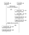
- FIG. 2 is a diagram illustrating an operation method of a terminal and a base station in the MU-MIMO system according to the exemplary embodiment of the present invention.
- FIG. 3 is a diagram illustrating an operation method of a terminal and a base station in a MU-MIMO system according to another exemplary embodiment of the present invention.
- FIG. 4 is a diagram illustrating an operation method of a terminal and a base station in a MU-MIMO system according to still another exemplary embodiment of the present invention.
- FIG. 5 is a diagram illustrating a terminal according to an exemplary embodiment of the present invention.
- a terminal may be called a mobile terminal (MT), a mobile station (MS), an advanced mobile station (AMS), a high reliability mobile station (HR-MS), a subscriber station (SS), a portable subscriber station (PSS), an access terminal (AT), an user equipment (UE), and the like and may include functions of all or some of the MT, the MS, the AMS, the HR-MS, the SS, the PSS, the AT, the UE, and the like
- a base station may be called an advanced base station (ABS), a high reliability base station (HR-BS), a nodeB, an evolved node B (eNodeB), an access point (AP), a radio access station (RAS), a base transceiver station (BTS), a mobile multihop relay (MMR)-BS, a relay station (RS) serving as a base station, a high reliability relay station (HR-RS) serving as a base station, and the like and may also include functions of all or some of the ABS, the HR-BS, the nodeB, the eNodeB, the AP, the RAS, the BTS, the MMR-BS, the RS, the HR-RS, AP, RAS, BTS, MMR-BS, RS, HR-RS, and the like.
- ABS advanced base station
- HR-BS high reliability base station
- eNodeB evolved node B
- AP access point
- RAS radio access station
- BTS base transceiver station
- MMR mobile
- a multi-user MIMO (hereinafter, referred to as ‘MU-MIMO’) system includes a base station having M antennas and K users (i.e., terminals) each having N antennas within a single cell. In this case, it is assumed that the base station uses the same resource to simultaneously provide services to a plurality of terminals (users).
- the terminal directly measures and reports channel quality indication (CQI) for the MU-MIMO. That is, typically, the terminal directly calculates the CQI for the MU-MIMO and feeds back the calculated CQI to the base station but the terminal according to the exemplary embodiment of the present invention does not directly calculate the CQI for the MU-MIMO.
- the terminal for the base station 100 to estimate the CQI for the MU-MIMO, the terminal feeds back only predetermined information (for example, information on interference signal intensity).
- predetermined information for example, information on interference signal intensity
- FIG. 1 is a diagram illustrating interference and a signal in a MU-MIMO environment according to an exemplary embodiment of the present invention.
- the base station 100 uses the same resource to transmit data to a terminal 200 and also transmit data to other terminals (not illustrated) other than the terminal 200 within a cell.
- the interference is represented by I b .
- the signal transmitted to the terminal 200 by the base station 100 is represented by S a .
- the CQI for the MU-MIMO is called ‘MU-CQI’ for convenience.
- the MU-CQI corresponds to a signal interference noise ratio (SINR) of the terminal 200 , and therefore the MU-CQI estimated by the base station 100 is defined as the following Equation 1.
- N represents background noise and interference signal intensity due to other cell
- constant 2 before N represents that the base station 100 divides power by 1 ⁇ 2 to transmit a data stream to two terminals using the same resource. Therefore, the constant 2 may be changed depending on the number of terminals which go through the MU-MIMO scheduling.
- subscripts a and b represent a precoding matrix index (PMI).
- PMI precoding matrix index
- a denominator represents the noise and the interference signal intensity which are undergone by the terminal 200 and a numerator represents signal intensity received by the terminal 100 .
- the denominator and the numerator are divided by N, the following Equation 2 is obtained.
- INR represents a interference-to-noise ratio, which may be replaced by a multi-user interference signal indicator (MUI) defined below.
- MUI multi-user interference signal indicator
- SNR a represents that a ratio of noise to self signal S a of a terminal (UE) and corresponds to the CQI (that is, CQI for a single user) used in a typical LTE system.
- the CQI is represented by CQI a . Therefore, the MU-CQI may finally be represented by the following Equation 3.
- the terminal 200 calculates information on the CQI a and the MUI used in the typical LTE system and transmits the calculated information.
- the terminal 200 calculates S a /N that is a ratio of noise N to the signal S a transmitted to the terminal 200 and feeds back the calculated S a /N to the base station 100 .
- the terminal 200 calculates I b /N that is an interference-to-noise ratio from the base station 100 and feeds back the calculated I b /N to the base station 100 . According to the exemplary embodiment of the present invention as described above, it is possible to reduce feedback overhead of the terminal.
- the base station 100 uses the CQI a and MUI b fed-back from the terminal 200 to finally calculate the MU-CQI depending on the above Equation 3. That is, the base station 100 may use the information (CQI a and MUI b ) fed-back from the terminal 200 to calculate the MU-CQI, thereby estimating an interference level between multi-users. As a result, the base station 100 may perform scheduling and link adaptation for the multi-user.
- the MUI information fed-back to the base station 100 by the terminal 200 may reduce the MUI overhead by the following method.
- the terminal 200 may simplify the MUI into the one bit information based on a ratio of the MUI and the SNR a depending on the following Equation 5, having a specific threshold value ⁇ .
- the terminal 200 allocates ‘0’ as the MUI information. Further, when the ratio of the MUI and the SNR a is larger than the threshold value ⁇ , the terminal 200 allocates ‘1’ as the MUI information. That is, the terminal 200 does not feedback the detailed interference level but divides and feeds back an interference beam having a very small interference level and an interference beam which does not have a very small interference level. As such, the MUI feedback information is reduced to one bit information, and therefore the MUI feedback overhead may be reduced.
- the feedback overhead may be more reduced.
- the MUI is less likely to be 1 in a channel in which spatial correlation (or angular spread) is large and the number of ‘1s’ is very small in the whole bit
- the feedback overhead may be more reduced.
- adjacent co-PMIs (PMI which may be co-scheduled in the self PMI) based on a chordal distance of the PMI of the terminal 200 show large interference intensity on average, and therefore the terminal 200 may transmit the MUI for the rest PMIs other than the adjacent co-PMI. Therefore, the overhead may be additionally reduced.
- the base station 100 and the terminal 200 need to share what the adjacent co-PMIs for each PMI are.
- FIG. 2 is a diagram illustrating the operation method of a terminal and a base station in the MU-MIMO system according to the exemplary embodiment of the present invention.
- the base station 100 transmits a reference signal for channel state measurement to the terminal 200 (S 210 ).
- the reference signal for the channel state measurement may be channel state information—reference signal (CSI-RS).
- CSI-RS channel state information—reference signal
- the CSI-RS may be appreciated by a person having ordinary skill in the art to which the present invention pertains and the detailed description thereof will be omitted.
- the terminal 200 uses the reference signal received from the base station 100 to calculate the CQI a of the above Equation 3 (S 220 ).
- the CQI a is the a ratio of a signal S a transmitted to the terminal 100 to noise, that is, the S a /N.
- the terminal 200 uses the reference signal received from the base station 100 to calculate the MUI of the above Equation 4 (S 230 ). That is, the terminal 200 calculates the MUI which is an interference-to-noise ratio for the rest PMIs other than the PMI selected by the terminal 200 (i.e., interference-to-noise ratio from the base station 100 ).
- the terminal 200 uses the above Equation 5 for the MUI calculated in step S 230 to reduce the number of bits (S 240 ). As described above, the number of bits may be one-bit, and therefore is called ‘one-bit MUI’ below. Further, the terminal 200 may compress the one-bit MUI (S 250 ).
- the terminal 200 feeds back the CQI a and the one-bit MUI (or compressed one-bit MUI) to the base station 100 (S 260 ). Further, the terminal 200 may also feedback the information on the PMI (for example, a in the above Equation 1) selected by the terminal 200 to the base station 100 .
- the base station 100 uses the CQI a and the one-bit MUI (or compressed one-bit MUI) which are fed-back from the terminal 200 to calculate the MU-CQI as the above Equation 3 (S 270 ).
- the base station 100 uses the MU-CQI calculated in step S 270 to perform the scheduling and link adaptation for the multi-user (S 280 ).
- the base station 100 may select the best multi-user based on the MU-CQI and reduce the interference between the multi-users.
- the one-bit MUI feedback method allows the terminal 200 to feedback the one-bit MUI without directly calculating the MU-CQI and allows the base station 100 to calculate the MU-CQI.
- the method allows the terminal 200 not to directly calculate the MU-CQI, and therefore the MUI-CQI calculated by the base station 200 may have a slight difference depending on specific receiving algorithms of terminal modem manufacturers.
- the terminal 200 may calculate the supplement MU-CQI (hereinafter, referred to as ‘MU-CQI’) and feedback the calculated MU-CQI to the base station 100 as described below.
- MU-CQI Supplement MU-CQI
- the MUI method described in FIG. 2 allows the base station 100 to schedule the MU-MIMO only in the terminal having a small interference. Therefore, a maximum value of the small interference signal intensity becomes ⁇ *SNR a by the above Equation 5. Therefore, when performing the MU-MIMO scheduling on s layers (the number of data streams transmitted to the same resource by the base station), the interference signal becomes s ⁇ 1. Further, the terminal 100 may obtain a lower bound of SINR as the following Equation 6 to calculate the MU-CQI′ and feedback the calculated MU-CQI′ to the base station. The right in Equation 6 corresponds to the supplement MU-CQI (i.e., MU-CQI′).
- the supplement MU-CQI (i.e., MU-CQI′) may be accurately calculated depending on the specific receiving algorithm of the terminal 200 and the terminal 200 feeds back the calculated MU-CQI′ to the base station 100 . Accordingly, the algorithm related problem of the terminal 200 may be solved.
- the terminal 200 may reduce the feedback overhead of the MU-CQI′ as follows.
- the terminal needs not feedback the MU-CQI′ corresponding to S ⁇ 1. Therefore, the terminal 200 may feedback the MU-CQI′ corresponding to S′ ⁇ 1 to reduce the overhead.
- the supplement MU-CQI may be fed-back in a sub-band unit, such that the overall overhead saving effect may be large.
- additional information for informing variable S′ for each sub-band may be required.
- FIG. 3 is a diagram illustrating an operation method of a terminal and a base station in a MU-MIMO system according to another exemplary embodiment of the present invention.
- Steps S 310 , S 320 , S 330 , S 340 , and S 350 of FIG. 3 are the same as steps S 210 , S 220 , S 230 , S 240 , and S 250 of FIG. 2 , respectively and the detailed description thereof will be omitted.
- the terminal 200 uses the above Equation 6 to calculate the supplement MU-CQI (MU-CQI′) (S 360 ). That is, the terminal 200 calculates the supplement MU-CQI′ which is the interference maximum value for the terminals having small interference.
- the terminal 200 feedbacks the CQI a , the one-bit MUI, and the MU-CQI′ to the base station 100 (S 370 ).
- the base station 100 uses the CQI a , the one-bit MUI, and the MU-CQI′ fed-back from the terminal 200 to calculate the MU-CQI as in the above Equation 3, (S 380 ).
- the base station 100 uses the MU-CQI calculated in step S 380 to perform the scheduling and link adaptation for the multi-user (S 390 ).
- the base station 100 may select the best multi-user based on the MU-CQI and reduce the interference between the multi-users.
- the threshold value ⁇ is differently set between a cell boundary terminal and a cell central terminal.
- the reason is that an inter-cell interference amount between the cell boundary terminal and the cell central terminal is different and therefore the effect of INR on the SINR is different.
- One example of the method for differently setting a threshold value ⁇ will be described below.
- an SNR difference between modulation coding scheme (MCS) levels corresponds to 1.8 dB.
- the threshold value ⁇ is adjusted depending on the following Equation 7.
- the threshold value ⁇ is represented by I.
- S corresponds to signal power and K corresponds to the number of users (terminals).
- K corresponds to the number of users (terminals).
- an SINR loss is equal to or less than 0.4 dB, compared to the case of removing the interference signal.
- the reason of setting I to 1 ⁇ 2 is to relieve the whole interference signal of (K ⁇ 1)/I to 0.5 times since the I is an interference level in the worst case.
- FIG. 4 is a diagram illustrating an operation method of a terminal and a base station in a MU-MIMO system according to still another exemplary embodiment of the present invention.
- the base station 100 transmits the reference signal for the channel state measurement to the terminal 200 (S 410 ).
- the reference signal for the channel state measurement may be the channel state information—reference signal (CSI-RS).
- CSI-RS channel state information—reference signal
- the CSI-RS may be appreciated by a person having ordinary skill in the art to which the present invention pertains and the detailed description thereof will be omitted.
- the terminal 200 reconfigures a subset consisting of precoding vectors orthogonal to each other in the whole codebook (S 420 ).
- W 7,0 , W 7,1 ⁇ a subset ⁇ W 0,0 , W 0,1 , W 2,0 , W 2,1 , W 4,0 , W 4,1 , W 6,0 , W 6,1 ⁇ is orthogonal to each other, and a subset is ⁇ W 1,0 , W 1,1 , W 3,0 , W 3,1 , W 5,0 , W 5,1 , W 7,0 , W 7,1 ⁇ orthogonal to each other.
- a subset ⁇ W 0,0 , W 0,1 , W 2,0 , W 2,1 , W 4,0 , W 4,1 , W 6,0 , W 6,1 ⁇ is called G 1 and a subset ⁇ W 1,0 , W 1,1 , W 3,0 , W 3,1 , W 5,0 , W 5,1 , W 7,0 , W 7,1 ⁇ is called G 2 .
- the subset becomes a co-MPI (PMI to candidate set which may be co-scheduled in the self PMI) for the MUI configuration.
- the terminal 200 selects its own PMI from the precoding vectors belonging to the subset and calculates the CQI a (S 430 ). That is, the terminal 100 selects its own PMI from the precoding vectors belonging to the subset G 1 and the subset G 2 and calculates the CQI a .
- the terminal 200 calculates the MUI for the subset to which the PMI selected in step S 430 belongs as an object (S 440 ). That is, the terminal 200 does not calculate the MUI for the whole subsets G 1 and G 2 but calculates the MUI only for the subset (for example, G 1 ) to which the PMI selected by the terminal 200 belongs.
- the method for calculating an MUI is the same as FIG. 2 and therefore the detailed description thereof will be omitted.
- the terminal 200 may calculate the one-bit MUI for the subset (for example, G 1 ) to which the PMI selected by the terminal 200 belongs.
- the terminal 200 feeds back the CQI a , the PMI selected by the terminal 200 , and the MUI calculated in the step S 440 (S 450 ).
- the base station 100 uses the information fed-back in step S 450 to calculate the MU-CQI (S 460 ). That is, the base station 100 uses the information fed-back in the step S 450 to calculate the MU-CQI for the subset G 1 to which the PMI selected by the terminal 200 belongs.
- the method for calculating an MUI is the same as FIG. 2 and therefore the detailed description thereof will be omitted.
- the base station 100 uses the MU-CQI calculated in the step S 460 to perform the scheduling and link adaptation for the multi-user (S 470 ).
- the base station 100 may select the best multi-user from the group (for example, G 1 ) orthogonal to each other, such that the interference between the multi-users may be more reduced.
- the terminal calculates only the MUI for the subsets and feedbacks the calculated MUI, such that the computation and the feedback amount may be more reduced.
- the terminal 200 may additionally feedback the interference signal level other than the MU-CQI feedback and the base station 100 may reconfigure the MUI to perform flexible scheduling similar to the MUI.
- FIG. 5 is a diagram illustrating a terminal according to an exemplary embodiment of the present invention.
- the terminal 200 includes a processor 210 , a memory 220 , and an RF module 230 .
- the processor 210 may be configured to implement procedures, methods, and functions described with reference to FIGS. 1 to 4 .
- the memory 220 is connected to the processor 210 and stores various types of information related to the operation of the processor 210 .
- the RF module 230 is connected to the antenna (not illustrated) and transmits or receives a radio signal. Further, the antenna may be implemented as a single antenna or a MIMO antenna.
Landscapes
- Engineering & Computer Science (AREA)
- Computer Networks & Wireless Communication (AREA)
- Signal Processing (AREA)
- Mobile Radio Communication Systems (AREA)
- Radio Transmission System (AREA)
Abstract
Description
In the above equation, SNRa may be the first value, S may be the number of layers of the base station, and γ may be the predetermined threshold value.
MUIb =I b /N (Equation 4)
I(dB)=0.4×S(dB)+13(dB scale) (Equation 8)
Claims (20)
Applications Claiming Priority (8)
| Application Number | Priority Date | Filing Date | Title |
|---|---|---|---|
| KR10-2014-0154474 | 2014-11-07 | ||
| KR20140154474 | 2014-11-07 | ||
| KR20150013033 | 2015-01-27 | ||
| KR10-2015-0013033 | 2015-01-27 | ||
| KR10-2015-0015557 | 2015-01-30 | ||
| KR20150015557 | 2015-01-30 | ||
| KR1020150154064A KR102372370B1 (en) | 2014-11-07 | 2015-11-03 | Terminal and operation method thereof in multi-user mult-input mult-output system |
| KR10-2015-0154064 | 2015-11-03 |
Publications (2)
| Publication Number | Publication Date |
|---|---|
| US20160134343A1 US20160134343A1 (en) | 2016-05-12 |
| US9800305B2 true US9800305B2 (en) | 2017-10-24 |
Family
ID=55913070
Family Applications (1)
| Application Number | Title | Priority Date | Filing Date |
|---|---|---|---|
| US14/935,107 Expired - Fee Related US9800305B2 (en) | 2014-11-07 | 2015-11-06 | Terminal and operation method thereof in multi-user multi-input multi-output system |
Country Status (1)
| Country | Link |
|---|---|
| US (1) | US9800305B2 (en) |
Families Citing this family (1)
| Publication number | Priority date | Publication date | Assignee | Title |
|---|---|---|---|---|
| CN111262611B (en) * | 2018-12-13 | 2021-07-06 | 维沃移动通信有限公司 | Method and apparatus for determining index of orthogonal basis vector |
Citations (14)
| Publication number | Priority date | Publication date | Assignee | Title |
|---|---|---|---|---|
| US20100035627A1 (en) | 2008-08-11 | 2010-02-11 | Qualcomm Incorporated | Method and apparatus for supporting distributed mimo in a wireless communication system |
| US20100103832A1 (en) * | 2007-08-31 | 2010-04-29 | Fujitsu Limited | Feedback Apparatus, Feedback Method, Scheduling Apparatus, And Scheduling Method |
| US20100195752A1 (en) | 2007-06-14 | 2010-08-05 | Electronics And Telecommunications Research Institute | Transmitter/receiver for controlling multiuser multiple input multiple output system and method thereof |
| US20120106470A1 (en) * | 2010-09-29 | 2012-05-03 | Samsung Electronics Co., Ltd., | Method and apparatus for feedback in multi-user multiple-input multiple-output (mu-mimo) communication system |
| US20120147831A1 (en) * | 2009-08-04 | 2012-06-14 | Panasonic Corporation | Channel quality reporting in a mobile communication system |
| US20120218913A1 (en) * | 2009-11-02 | 2012-08-30 | Pantech Co., Ltd. | Channel information feedback device and method thereof, and mode switching method, communication terminal device, and base station system using same |
| US20130322375A1 (en) * | 2012-05-31 | 2013-12-05 | Samsung Electronics Co., Ltd | Apparatus and method of cooperating with multiple base stations in wireless communication system |
| US20140010318A1 (en) * | 2010-12-16 | 2014-01-09 | Lg Electronics Inc. | Method for reporting channel status information in a multi antenna wireless communication system and device for same |
| US20140133334A1 (en) * | 2011-04-22 | 2014-05-15 | Ntt Docomo, Inc. | Method for determining multi-user channel quality in mobile communication system, and user terminal and base station therefor |
| US20140226735A1 (en) | 2010-04-02 | 2014-08-14 | Interdigital Patent Holdings, Inc. | Systems And Methods For HSDPA Multi-User MIMO Operation |
| US20140254517A1 (en) | 2013-03-08 | 2014-09-11 | Electronics & Telecommunications Research Institute | Method for multi-input multi-output communication in large-scale antenna system |
| KR20140110759A (en) | 2013-03-08 | 2014-09-17 | 한국전자통신연구원 | Method for multi-input multi-output communication in large-scale antenna system |
| US20140294110A1 (en) | 2013-04-01 | 2014-10-02 | Electronics And Telecommunications Research Institute | Method and apparatus for opportunistic interference alignment (oia) in multi-user multiple-input multiple-output (mu-mimo) transmission |
| US8953475B2 (en) * | 2012-01-30 | 2015-02-10 | Telefonaktiebolaget L M Ericsson (Publ) | Base station, user equipment, and methods therein in a communications system |
-
2015
- 2015-11-06 US US14/935,107 patent/US9800305B2/en not_active Expired - Fee Related
Patent Citations (14)
| Publication number | Priority date | Publication date | Assignee | Title |
|---|---|---|---|---|
| US20100195752A1 (en) | 2007-06-14 | 2010-08-05 | Electronics And Telecommunications Research Institute | Transmitter/receiver for controlling multiuser multiple input multiple output system and method thereof |
| US20100103832A1 (en) * | 2007-08-31 | 2010-04-29 | Fujitsu Limited | Feedback Apparatus, Feedback Method, Scheduling Apparatus, And Scheduling Method |
| US20100035627A1 (en) | 2008-08-11 | 2010-02-11 | Qualcomm Incorporated | Method and apparatus for supporting distributed mimo in a wireless communication system |
| US20120147831A1 (en) * | 2009-08-04 | 2012-06-14 | Panasonic Corporation | Channel quality reporting in a mobile communication system |
| US20120218913A1 (en) * | 2009-11-02 | 2012-08-30 | Pantech Co., Ltd. | Channel information feedback device and method thereof, and mode switching method, communication terminal device, and base station system using same |
| US20140226735A1 (en) | 2010-04-02 | 2014-08-14 | Interdigital Patent Holdings, Inc. | Systems And Methods For HSDPA Multi-User MIMO Operation |
| US20120106470A1 (en) * | 2010-09-29 | 2012-05-03 | Samsung Electronics Co., Ltd., | Method and apparatus for feedback in multi-user multiple-input multiple-output (mu-mimo) communication system |
| US20140010318A1 (en) * | 2010-12-16 | 2014-01-09 | Lg Electronics Inc. | Method for reporting channel status information in a multi antenna wireless communication system and device for same |
| US20140133334A1 (en) * | 2011-04-22 | 2014-05-15 | Ntt Docomo, Inc. | Method for determining multi-user channel quality in mobile communication system, and user terminal and base station therefor |
| US8953475B2 (en) * | 2012-01-30 | 2015-02-10 | Telefonaktiebolaget L M Ericsson (Publ) | Base station, user equipment, and methods therein in a communications system |
| US20130322375A1 (en) * | 2012-05-31 | 2013-12-05 | Samsung Electronics Co., Ltd | Apparatus and method of cooperating with multiple base stations in wireless communication system |
| US20140254517A1 (en) | 2013-03-08 | 2014-09-11 | Electronics & Telecommunications Research Institute | Method for multi-input multi-output communication in large-scale antenna system |
| KR20140110759A (en) | 2013-03-08 | 2014-09-17 | 한국전자통신연구원 | Method for multi-input multi-output communication in large-scale antenna system |
| US20140294110A1 (en) | 2013-04-01 | 2014-10-02 | Electronics And Telecommunications Research Institute | Method and apparatus for opportunistic interference alignment (oia) in multi-user multiple-input multiple-output (mu-mimo) transmission |
Non-Patent Citations (1)
| Title |
|---|
| "Impact of MU-CSI feedback on the EBF/FD-MIMO performance", 3GPP TSG RAN WG1 Meeting, Apr. 20-24, 2015, pp. 1-5. |
Also Published As
| Publication number | Publication date |
|---|---|
| US20160134343A1 (en) | 2016-05-12 |
Similar Documents
| Publication | Publication Date | Title |
|---|---|---|
| US10420090B2 (en) | Communication technique using CSI-RS in mobile communication system | |
| US10567066B2 (en) | Apparatus and method for performing precoding in wireless communication system using massive antenna | |
| KR102549318B1 (en) | Method and apparatus for csi-rs resource repetition in wireless communication system | |
| US11005612B2 (en) | Device and method for non-orthogonal multiple access in wireless communication system | |
| US10355809B2 (en) | Channel state information feedback method and user equipment | |
| US8848631B2 (en) | Wireless communication apparatus, wireless communication system, and wireless communication method | |
| CN110832803B (en) | Interference measurement and channel state information feedback for multi-user multiple-input multiple-output | |
| KR101590198B1 (en) | Method of multi cell cooperation in wireless communication system | |
| US10263681B2 (en) | Method and apparatus for reporting periodic channel state information in mobile communication system using massive array antennas | |
| US9843409B2 (en) | Multiple-input multiple-output method for orthogonal frequency division multiplexing based communication system | |
| US10069550B2 (en) | Method and apparatus for generating and reporting feedback information in mobile communication system | |
| KR101060857B1 (en) | Method and apparatus for transmitting data in mimo communication system | |
| US10985829B2 (en) | Beam management systems and methods | |
| EP4044537A1 (en) | Device and method for estimating channel in wireless communication system | |
| RU2609593C2 (en) | Method and device for transmitting and receiving feedback signal in mobile communication system | |
| US20240015557A1 (en) | Method and device for transmitting reference signal, control signal, and data in mobile communication system | |
| US9295062B2 (en) | Method and arrangement for power allocation in communication systems | |
| US11190243B2 (en) | Control device, network node and methods for allocating resources | |
| US20210321423A1 (en) | Method and system for scheduling a pool of resources to a plurality of user equipments | |
| KR101807931B1 (en) | Mobile station and reporting method | |
| US9800305B2 (en) | Terminal and operation method thereof in multi-user multi-input multi-output system | |
| US10171221B2 (en) | Scheduling method and apparatus of multi-antenna communication system, and method and apparatus for feeding-back channel quality indicator | |
| KR102372370B1 (en) | Terminal and operation method thereof in multi-user mult-input mult-output system | |
| US10028214B2 (en) | Base station and cell selection method | |
| US20170111090A1 (en) | Terminal and base station in distributed antenna system and operation method thereof |
Legal Events
| Date | Code | Title | Description |
|---|---|---|---|
| AS | Assignment |
Owner name: ELECTRONICS AND TELECOMMUNICATIONS RESEARCH INSTIT Free format text: ASSIGNMENT OF ASSIGNORS INTEREST;ASSIGNORS:NAM, JUNYOUNG;SHIN, WOORAM;MOON, SUNG-HYUN;AND OTHERS;REEL/FRAME:036982/0993 Effective date: 20151020 |
|
| STCF | Information on status: patent grant |
Free format text: PATENTED CASE |
|
| FEPP | Fee payment procedure |
Free format text: MAINTENANCE FEE REMINDER MAILED (ORIGINAL EVENT CODE: REM.); ENTITY STATUS OF PATENT OWNER: SMALL ENTITY |
|
| LAPS | Lapse for failure to pay maintenance fees |
Free format text: PATENT EXPIRED FOR FAILURE TO PAY MAINTENANCE FEES (ORIGINAL EVENT CODE: EXP.); ENTITY STATUS OF PATENT OWNER: SMALL ENTITY |
|
| STCH | Information on status: patent discontinuation |
Free format text: PATENT EXPIRED DUE TO NONPAYMENT OF MAINTENANCE FEES UNDER 37 CFR 1.362 |
|
| FP | Lapsed due to failure to pay maintenance fee |
Effective date: 20211024 |