US9790247B2 - Cobalt-containing compounds, their synthesis, and use in cobalt-containing film deposition - Google Patents
Cobalt-containing compounds, their synthesis, and use in cobalt-containing film deposition Download PDFInfo
- Publication number
- US9790247B2 US9790247B2 US14/765,098 US201414765098A US9790247B2 US 9790247 B2 US9790247 B2 US 9790247B2 US 201414765098 A US201414765098 A US 201414765098A US 9790247 B2 US9790247 B2 US 9790247B2
- Authority
- US
- United States
- Prior art keywords
- cosi
- sih
- cobalt
- nme
- compound
- Prior art date
- Legal status (The legal status is an assumption and is not a legal conclusion. Google has not performed a legal analysis and makes no representation as to the accuracy of the status listed.)
- Active, expires
Links
- 150000001875 compounds Chemical class 0.000 title claims abstract description 120
- 229910017052 cobalt Inorganic materials 0.000 title claims abstract description 87
- 239000010941 cobalt Substances 0.000 title claims abstract description 87
- GUTLYIVDDKVIGB-UHFFFAOYSA-N cobalt atom Chemical compound [Co] GUTLYIVDDKVIGB-UHFFFAOYSA-N 0.000 title claims abstract description 79
- 230000008021 deposition Effects 0.000 title claims abstract description 23
- 230000015572 biosynthetic process Effects 0.000 title abstract description 17
- 238000003786 synthesis reaction Methods 0.000 title abstract description 13
- 239000003446 ligand Substances 0.000 claims abstract description 22
- 229930195733 hydrocarbon Natural products 0.000 claims abstract description 13
- 150000002430 hydrocarbons Chemical class 0.000 claims abstract description 13
- 125000004122 cyclic group Chemical group 0.000 claims abstract description 12
- 125000002924 primary amino group Chemical group [H]N([H])* 0.000 claims abstract description 10
- 239000001257 hydrogen Substances 0.000 claims abstract description 9
- 229910052739 hydrogen Inorganic materials 0.000 claims abstract description 9
- 239000004215 Carbon black (E152) Substances 0.000 claims abstract description 7
- 229910052736 halogen Inorganic materials 0.000 claims abstract description 7
- 150000002367 halogens Chemical class 0.000 claims abstract description 7
- 125000000467 secondary amino group Chemical group [H]N([*:1])[*:2] 0.000 claims abstract description 5
- OIQOECYRLBNNBQ-UHFFFAOYSA-N carbon monoxide;cobalt Chemical compound [Co].[O+]#[C-].[O+]#[C-].[O+]#[C-].[O+]#[C-] OIQOECYRLBNNBQ-UHFFFAOYSA-N 0.000 claims description 84
- 229910019001 CoSi Inorganic materials 0.000 claims description 66
- 238000000034 method Methods 0.000 claims description 47
- 238000000151 deposition Methods 0.000 claims description 42
- 238000000231 atomic layer deposition Methods 0.000 claims description 36
- 239000000203 mixture Substances 0.000 claims description 33
- 239000000758 substrate Substances 0.000 claims description 33
- 239000012495 reaction gas Substances 0.000 claims description 29
- XMIJDTGORVPYLW-UHFFFAOYSA-N [SiH2] Chemical compound [SiH2] XMIJDTGORVPYLW-UHFFFAOYSA-N 0.000 claims description 25
- 238000005229 chemical vapour deposition Methods 0.000 claims description 21
- 125000002147 dimethylamino group Chemical group [H]C([H])([H])N(*)C([H])([H])[H] 0.000 claims description 21
- -1 Si(NEt2)3Co(CO)4 Chemical compound 0.000 claims description 17
- ZMANZCXQSJIPKH-UHFFFAOYSA-N Triethylamine Chemical compound CCN(CC)CC ZMANZCXQSJIPKH-UHFFFAOYSA-N 0.000 claims description 14
- 239000003153 chemical reaction reagent Substances 0.000 claims description 12
- 150000003254 radicals Chemical class 0.000 claims description 12
- 230000001590 oxidative effect Effects 0.000 claims description 10
- QTBSBXVTEAMEQO-UHFFFAOYSA-N Acetic acid Chemical compound CC(O)=O QTBSBXVTEAMEQO-UHFFFAOYSA-N 0.000 claims description 9
- 229910003986 SicO Inorganic materials 0.000 claims description 9
- 229910021332 silicide Inorganic materials 0.000 claims description 9
- 239000003638 chemical reducing agent Substances 0.000 claims description 8
- 238000000623 plasma-assisted chemical vapour deposition Methods 0.000 claims description 8
- GETQZCLCWQTVFV-UHFFFAOYSA-N trimethylamine Chemical compound CN(C)C GETQZCLCWQTVFV-UHFFFAOYSA-N 0.000 claims description 8
- 238000001505 atmospheric-pressure chemical vapour deposition Methods 0.000 claims description 7
- 238000004518 low pressure chemical vapour deposition Methods 0.000 claims description 7
- 125000004435 hydrogen atom Chemical group [H]* 0.000 claims description 6
- 239000007800 oxidant agent Substances 0.000 claims description 6
- FVBUAEGBCNSCDD-UHFFFAOYSA-N silicide(4-) Chemical compound [Si-4] FVBUAEGBCNSCDD-UHFFFAOYSA-N 0.000 claims description 6
- 229910003828 SiH3 Inorganic materials 0.000 claims description 5
- OLRJXMHANKMLTD-UHFFFAOYSA-N silyl Chemical compound [SiH3] OLRJXMHANKMLTD-UHFFFAOYSA-N 0.000 claims description 5
- RTZKZFJDLAIYFH-UHFFFAOYSA-N Diethyl ether Chemical compound CCOCC RTZKZFJDLAIYFH-UHFFFAOYSA-N 0.000 claims description 4
- BLRPTPMANUNPDV-UHFFFAOYSA-N Silane Chemical compound [SiH4] BLRPTPMANUNPDV-UHFFFAOYSA-N 0.000 claims description 4
- IVMYJDGYRUAWML-UHFFFAOYSA-N cobalt(ii) oxide Chemical compound [Co]=O IVMYJDGYRUAWML-UHFFFAOYSA-N 0.000 claims description 4
- 230000007935 neutral effect Effects 0.000 claims description 4
- RHUYHJGZWVXEHW-UHFFFAOYSA-N 1,1-Dimethyhydrazine Chemical compound CN(C)N RHUYHJGZWVXEHW-UHFFFAOYSA-N 0.000 claims description 3
- QGZKDVFQNNGYKY-UHFFFAOYSA-N Ammonia Chemical compound N QGZKDVFQNNGYKY-UHFFFAOYSA-N 0.000 claims description 3
- MHAJPDPJQMAIIY-UHFFFAOYSA-N Hydrogen peroxide Chemical compound OO MHAJPDPJQMAIIY-UHFFFAOYSA-N 0.000 claims description 3
- 229910007264 Si2H6 Inorganic materials 0.000 claims description 3
- 229910005096 Si3H8 Inorganic materials 0.000 claims description 3
- KZZFGAYUBYCTNX-UHFFFAOYSA-N diethylsilicon Chemical compound CC[Si]CC KZZFGAYUBYCTNX-UHFFFAOYSA-N 0.000 claims description 3
- PZPGRFITIJYNEJ-UHFFFAOYSA-N disilane Chemical compound [SiH3][SiH3] PZPGRFITIJYNEJ-UHFFFAOYSA-N 0.000 claims description 3
- 239000012530 fluid Substances 0.000 claims description 3
- HKOOXMFOFWEVGF-UHFFFAOYSA-N phenylhydrazine Chemical compound NNC1=CC=CC=C1 HKOOXMFOFWEVGF-UHFFFAOYSA-N 0.000 claims description 3
- 229940067157 phenylhydrazine Drugs 0.000 claims description 3
- AQRLNPVMDITEJU-UHFFFAOYSA-N triethylsilane Substances CC[SiH](CC)CC AQRLNPVMDITEJU-UHFFFAOYSA-N 0.000 claims description 3
- QXTIBZLKQPJVII-UHFFFAOYSA-N triethylsilicon Chemical compound CC[Si](CC)CC QXTIBZLKQPJVII-UHFFFAOYSA-N 0.000 claims description 3
- PQDJYEQOELDLCP-UHFFFAOYSA-N trimethylsilane Chemical compound C[SiH](C)C PQDJYEQOELDLCP-UHFFFAOYSA-N 0.000 claims description 3
- JCXJVPUVTGWSNB-UHFFFAOYSA-N Nitrogen dioxide Chemical compound O=[N]=O JCXJVPUVTGWSNB-UHFFFAOYSA-N 0.000 claims description 2
- UFHFLCQGNIYNRP-UHFFFAOYSA-N Hydrogen Chemical compound [H][H] UFHFLCQGNIYNRP-UHFFFAOYSA-N 0.000 abstract description 10
- 239000010408 film Substances 0.000 description 44
- 239000002243 precursor Substances 0.000 description 35
- 238000006243 chemical reaction Methods 0.000 description 22
- 238000003756 stirring Methods 0.000 description 22
- 239000007789 gas Substances 0.000 description 13
- 230000008569 process Effects 0.000 description 10
- 229910052751 metal Inorganic materials 0.000 description 8
- 239000002184 metal Substances 0.000 description 8
- 229910021012 Co2(CO)8 Inorganic materials 0.000 description 7
- 238000000137 annealing Methods 0.000 description 7
- 239000000463 material Substances 0.000 description 7
- WZRJTRPJURQBRM-UHFFFAOYSA-N 4-amino-n-(5-methyl-1,2-oxazol-3-yl)benzenesulfonamide;5-[(3,4,5-trimethoxyphenyl)methyl]pyrimidine-2,4-diamine Chemical group O1C(C)=CC(NS(=O)(=O)C=2C=CC(N)=CC=2)=N1.COC1=C(OC)C(OC)=CC(CC=2C(=NC(N)=NC=2)N)=C1 WZRJTRPJURQBRM-UHFFFAOYSA-N 0.000 description 6
- YMWUJEATGCHHMB-UHFFFAOYSA-N Dichloromethane Chemical compound ClCCl YMWUJEATGCHHMB-UHFFFAOYSA-N 0.000 description 6
- YXFVVABEGXRONW-UHFFFAOYSA-N Toluene Chemical compound CC1=CC=CC=C1 YXFVVABEGXRONW-UHFFFAOYSA-N 0.000 description 6
- 125000000217 alkyl group Chemical group 0.000 description 6
- 125000000999 tert-butyl group Chemical group [H]C([H])([H])C(*)(C([H])([H])[H])C([H])([H])[H] 0.000 description 6
- XOLBLPGZBRYERU-UHFFFAOYSA-N tin dioxide Chemical compound O=[Sn]=O XOLBLPGZBRYERU-UHFFFAOYSA-N 0.000 description 6
- GWEVSGVZZGPLCZ-UHFFFAOYSA-N Titan oxide Chemical compound O=[Ti]=O GWEVSGVZZGPLCZ-UHFFFAOYSA-N 0.000 description 5
- 0 [1*][Si]([2*])([3*])[Co].[4*][Si]([5*])(C)[Co].[C-]#[O+].[C-]#[O+].[C-]#[O+].[C-]#[O+].[C-]#[O+].[C-]#[O+].[C-]#[O+].[C-]#[O+] Chemical compound [1*][Si]([2*])([3*])[Co].[4*][Si]([5*])(C)[Co].[C-]#[O+].[C-]#[O+].[C-]#[O+].[C-]#[O+].[C-]#[O+].[C-]#[O+].[C-]#[O+].[C-]#[O+] 0.000 description 5
- 239000012298 atmosphere Substances 0.000 description 5
- 125000001449 isopropyl group Chemical group [H]C([H])([H])C([H])(*)C([H])([H])[H] 0.000 description 5
- 125000002496 methyl group Chemical group [H]C([H])([H])* 0.000 description 5
- 238000012545 processing Methods 0.000 description 5
- 238000010926 purge Methods 0.000 description 5
- VYPSYNLAJGMNEJ-UHFFFAOYSA-N Silicium dioxide Chemical compound O=[Si]=O VYPSYNLAJGMNEJ-UHFFFAOYSA-N 0.000 description 4
- MCMNRKCIXSYSNV-UHFFFAOYSA-N Zirconium dioxide Chemical compound O=[Zr]=O MCMNRKCIXSYSNV-UHFFFAOYSA-N 0.000 description 4
- 239000012159 carrier gas Substances 0.000 description 4
- 229910000428 cobalt oxide Inorganic materials 0.000 description 4
- 239000010949 copper Substances 0.000 description 4
- 238000005137 deposition process Methods 0.000 description 4
- 239000010955 niobium Substances 0.000 description 4
- 239000004065 semiconductor Substances 0.000 description 4
- 239000002904 solvent Substances 0.000 description 4
- 239000010409 thin film Substances 0.000 description 4
- OKTJSMMVPCPJKN-UHFFFAOYSA-N Carbon Chemical compound [C] OKTJSMMVPCPJKN-UHFFFAOYSA-N 0.000 description 3
- RYGMFSIKBFXOCR-UHFFFAOYSA-N Copper Chemical compound [Cu] RYGMFSIKBFXOCR-UHFFFAOYSA-N 0.000 description 3
- WSFSSNUMVMOOMR-UHFFFAOYSA-N Formaldehyde Chemical compound O=C WSFSSNUMVMOOMR-UHFFFAOYSA-N 0.000 description 3
- XEEYBQQBJWHFJM-UHFFFAOYSA-N Iron Chemical compound [Fe] XEEYBQQBJWHFJM-UHFFFAOYSA-N 0.000 description 3
- XLOMVQKBTHCTTD-UHFFFAOYSA-N Zinc monoxide Chemical compound [Zn]=O XLOMVQKBTHCTTD-UHFFFAOYSA-N 0.000 description 3
- 150000001412 amines Chemical class 0.000 description 3
- QVGXLLKOCUKJST-UHFFFAOYSA-N atomic oxygen Chemical compound [O] QVGXLLKOCUKJST-UHFFFAOYSA-N 0.000 description 3
- 229910052799 carbon Inorganic materials 0.000 description 3
- 229910052802 copper Inorganic materials 0.000 description 3
- 238000004821 distillation Methods 0.000 description 3
- 238000005516 engineering process Methods 0.000 description 3
- 125000000524 functional group Chemical group 0.000 description 3
- 238000011065 in-situ storage Methods 0.000 description 3
- 229910052747 lanthanoid Inorganic materials 0.000 description 3
- 150000002602 lanthanoids Chemical class 0.000 description 3
- 238000004519 manufacturing process Methods 0.000 description 3
- 229910052758 niobium Inorganic materials 0.000 description 3
- 150000004767 nitrides Chemical class 0.000 description 3
- 239000001301 oxygen Substances 0.000 description 3
- 229910052760 oxygen Inorganic materials 0.000 description 3
- FZHAPNGMFPVSLP-UHFFFAOYSA-N silanamine Chemical compound [SiH3]N FZHAPNGMFPVSLP-UHFFFAOYSA-N 0.000 description 3
- 229910052710 silicon Inorganic materials 0.000 description 3
- 239000007787 solid Substances 0.000 description 3
- 229910052712 strontium Inorganic materials 0.000 description 3
- 230000008022 sublimation Effects 0.000 description 3
- 229910052723 transition metal Inorganic materials 0.000 description 3
- 238000005019 vapor deposition process Methods 0.000 description 3
- 230000008016 vaporization Effects 0.000 description 3
- IJGRMHOSHXDMSA-UHFFFAOYSA-N Atomic nitrogen Chemical compound N#N IJGRMHOSHXDMSA-UHFFFAOYSA-N 0.000 description 2
- HMRTVAKZCZVXLV-UHFFFAOYSA-N C[Si](C)(C)[Co] Chemical compound C[Si](C)(C)[Co] HMRTVAKZCZVXLV-UHFFFAOYSA-N 0.000 description 2
- QPLDLSVMHZLSFG-UHFFFAOYSA-N Copper oxide Chemical compound [Cu]=O QPLDLSVMHZLSFG-UHFFFAOYSA-N 0.000 description 2
- YNQLUTRBYVCPMQ-UHFFFAOYSA-N Ethylbenzene Chemical compound CCC1=CC=CC=C1 YNQLUTRBYVCPMQ-UHFFFAOYSA-N 0.000 description 2
- PXHVJJICTQNCMI-UHFFFAOYSA-N Nickel Chemical compound [Ni] PXHVJJICTQNCMI-UHFFFAOYSA-N 0.000 description 2
- XUIMIQQOPSSXEZ-UHFFFAOYSA-N Silicon Chemical compound [Si] XUIMIQQOPSSXEZ-UHFFFAOYSA-N 0.000 description 2
- 229910052782 aluminium Inorganic materials 0.000 description 2
- 229910052788 barium Inorganic materials 0.000 description 2
- 230000004888 barrier function Effects 0.000 description 2
- 230000005587 bubbling Effects 0.000 description 2
- 125000000484 butyl group Chemical group [H]C([*])([H])C([H])([H])C([H])([H])C([H])([H])[H] 0.000 description 2
- 229910052791 calcium Inorganic materials 0.000 description 2
- 238000000576 coating method Methods 0.000 description 2
- AIOWANYIHSOXQY-UHFFFAOYSA-N cobalt silicon Chemical group [Si].[Co] AIOWANYIHSOXQY-UHFFFAOYSA-N 0.000 description 2
- 229910052681 coesite Inorganic materials 0.000 description 2
- 229910052906 cristobalite Inorganic materials 0.000 description 2
- 125000006165 cyclic alkyl group Chemical group 0.000 description 2
- DIOQZVSQGTUSAI-UHFFFAOYSA-N decane Chemical compound CCCCCCCCCC DIOQZVSQGTUSAI-UHFFFAOYSA-N 0.000 description 2
- SNRUBQQJIBEYMU-UHFFFAOYSA-N dodecane Chemical compound CCCCCCCCCCCC SNRUBQQJIBEYMU-UHFFFAOYSA-N 0.000 description 2
- 125000001495 ethyl group Chemical group [H]C([H])([H])C([H])([H])* 0.000 description 2
- CJNBYAVZURUTKZ-UHFFFAOYSA-N hafnium(IV) oxide Inorganic materials O=[Hf]=O CJNBYAVZURUTKZ-UHFFFAOYSA-N 0.000 description 2
- 238000002513 implantation Methods 0.000 description 2
- 238000005468 ion implantation Methods 0.000 description 2
- 150000002500 ions Chemical class 0.000 description 2
- 229910052742 iron Inorganic materials 0.000 description 2
- 125000000959 isobutyl group Chemical group [H]C([H])([H])C([H])(C([H])([H])[H])C([H])([H])* 0.000 description 2
- 239000007788 liquid Substances 0.000 description 2
- 229910052749 magnesium Inorganic materials 0.000 description 2
- WPBNNNQJVZRUHP-UHFFFAOYSA-L manganese(2+);methyl n-[[2-(methoxycarbonylcarbamothioylamino)phenyl]carbamothioyl]carbamate;n-[2-(sulfidocarbothioylamino)ethyl]carbamodithioate Chemical compound [Mn+2].[S-]C(=S)NCCNC([S-])=S.COC(=O)NC(=S)NC1=CC=CC=C1NC(=S)NC(=O)OC WPBNNNQJVZRUHP-UHFFFAOYSA-L 0.000 description 2
- 125000001436 propyl group Chemical group [H]C([*])([H])C([H])([H])C([H])([H])[H] 0.000 description 2
- 125000002914 sec-butyl group Chemical group [H]C([H])([H])C([H])([H])C([H])(*)C([H])([H])[H] 0.000 description 2
- 239000010703 silicon Substances 0.000 description 2
- 239000000377 silicon dioxide Substances 0.000 description 2
- 229910052682 stishovite Inorganic materials 0.000 description 2
- 238000000859 sublimation Methods 0.000 description 2
- 239000000126 substance Substances 0.000 description 2
- 229910052715 tantalum Inorganic materials 0.000 description 2
- 229910052718 tin Inorganic materials 0.000 description 2
- OGIDPMRJRNCKJF-UHFFFAOYSA-N titanium oxide Inorganic materials [Ti]=O OGIDPMRJRNCKJF-UHFFFAOYSA-N 0.000 description 2
- 150000003624 transition metals Chemical class 0.000 description 2
- 229910052905 tridymite Inorganic materials 0.000 description 2
- 238000009834 vaporization Methods 0.000 description 2
- 229910052727 yttrium Inorganic materials 0.000 description 2
- ITWBWJFEJCHKSN-UHFFFAOYSA-N 1,4,7-triazonane Chemical compound C1CNCCNCCN1 ITWBWJFEJCHKSN-UHFFFAOYSA-N 0.000 description 1
- JBRZTFJDHDCESZ-UHFFFAOYSA-N AsGa Chemical compound [As]#[Ga] JBRZTFJDHDCESZ-UHFFFAOYSA-N 0.000 description 1
- RVQCZWDJGHIAFG-UHFFFAOYSA-N CN(C)[Si](C)([Co])N(C)C.[C-]#[O+].[C-]#[O+].[C-]#[O+].[C-]#[O+].[C-]#[O+].[C-]#[O+].[C-]#[O+].[C-]#[O+].[C-]#[O+].[C-]#[O+].[C-]#[O+].[C-]#[O+].[C-]#[O+].[C-]#[O+].[C-]#[O+].[C-]#[O+].[H][Si]([Co])(N(CC)CC)N(CC)CC.[H][Si]([Co])(NC(C)(C)C)NC(C)(C)C.[H][Si]([H])([Co])[Ni](CCC)CCC Chemical compound CN(C)[Si](C)([Co])N(C)C.[C-]#[O+].[C-]#[O+].[C-]#[O+].[C-]#[O+].[C-]#[O+].[C-]#[O+].[C-]#[O+].[C-]#[O+].[C-]#[O+].[C-]#[O+].[C-]#[O+].[C-]#[O+].[C-]#[O+].[C-]#[O+].[C-]#[O+].[C-]#[O+].[H][Si]([Co])(N(CC)CC)N(CC)CC.[H][Si]([Co])(NC(C)(C)C)NC(C)(C)C.[H][Si]([H])([Co])[Ni](CCC)CCC RVQCZWDJGHIAFG-UHFFFAOYSA-N 0.000 description 1
- UGFAIRIUMAVXCW-UHFFFAOYSA-N Carbon monoxide Chemical compound [O+]#[C-] UGFAIRIUMAVXCW-UHFFFAOYSA-N 0.000 description 1
- 229910021244 Co2Si Inorganic materials 0.000 description 1
- 229910002451 CoOx Inorganic materials 0.000 description 1
- 239000005751 Copper oxide Substances 0.000 description 1
- VGGSQFUCUMXWEO-UHFFFAOYSA-N Ethene Chemical compound C=C VGGSQFUCUMXWEO-UHFFFAOYSA-N 0.000 description 1
- 239000005977 Ethylene Substances 0.000 description 1
- 125000000773 L-serino group Chemical group [H]OC(=O)[C@@]([H])(N([H])*)C([H])([H])O[H] 0.000 description 1
- CTQNGGLPUBDAKN-UHFFFAOYSA-N O-Xylene Chemical compound CC1=CC=CC=C1C CTQNGGLPUBDAKN-UHFFFAOYSA-N 0.000 description 1
- 229930040373 Paraformaldehyde Natural products 0.000 description 1
- KJTLSVCANCCWHF-UHFFFAOYSA-N Ruthenium Chemical compound [Ru] KJTLSVCANCCWHF-UHFFFAOYSA-N 0.000 description 1
- 241001275117 Seres Species 0.000 description 1
- 229910052581 Si3N4 Inorganic materials 0.000 description 1
- 229910004200 TaSiN Inorganic materials 0.000 description 1
- 229910008482 TiSiN Inorganic materials 0.000 description 1
- ATJFFYVFTNAWJD-UHFFFAOYSA-N Tin Chemical compound [Sn] ATJFFYVFTNAWJD-UHFFFAOYSA-N 0.000 description 1
- 238000003848 UV Light-Curing Methods 0.000 description 1
- CZSILKLDMPCKGR-UHFFFAOYSA-N [C]=O.[C]=O.[C]=O.[C]=O.F[Si](F)(F)[Co] Chemical group [C]=O.[C]=O.[C]=O.[C]=O.F[Si](F)(F)[Co] CZSILKLDMPCKGR-UHFFFAOYSA-N 0.000 description 1
- 230000004913 activation Effects 0.000 description 1
- 229910045601 alloy Inorganic materials 0.000 description 1
- 239000000956 alloy Substances 0.000 description 1
- XAGFODPZIPBFFR-UHFFFAOYSA-N aluminium Chemical compound [Al] XAGFODPZIPBFFR-UHFFFAOYSA-N 0.000 description 1
- PNEYBMLMFCGWSK-UHFFFAOYSA-N aluminium oxide Inorganic materials [O-2].[O-2].[O-2].[Al+3].[Al+3] PNEYBMLMFCGWSK-UHFFFAOYSA-N 0.000 description 1
- 229910052787 antimony Inorganic materials 0.000 description 1
- 229910052785 arsenic Inorganic materials 0.000 description 1
- DSAJWYNOEDNPEQ-UHFFFAOYSA-N barium atom Chemical compound [Ba] DSAJWYNOEDNPEQ-UHFFFAOYSA-N 0.000 description 1
- 229910052454 barium strontium titanate Inorganic materials 0.000 description 1
- 230000009286 beneficial effect Effects 0.000 description 1
- 229910052797 bismuth Inorganic materials 0.000 description 1
- 229910052794 bromium Inorganic materials 0.000 description 1
- 125000004432 carbon atom Chemical group C* 0.000 description 1
- 229910002091 carbon monoxide Inorganic materials 0.000 description 1
- 239000003054 catalyst Substances 0.000 description 1
- 238000006555 catalytic reaction Methods 0.000 description 1
- 239000003795 chemical substances by application Substances 0.000 description 1
- 229910052801 chlorine Inorganic materials 0.000 description 1
- 239000011248 coating agent Substances 0.000 description 1
- 150000001869 cobalt compounds Chemical class 0.000 description 1
- SKNBMIPMZPHKFP-UHFFFAOYSA-N cobalt;trichlorosilicon Chemical compound [Co].Cl[Si](Cl)Cl SKNBMIPMZPHKFP-UHFFFAOYSA-N 0.000 description 1
- 238000011109 contamination Methods 0.000 description 1
- 229910000431 copper oxide Inorganic materials 0.000 description 1
- 229910052593 corundum Inorganic materials 0.000 description 1
- 125000000113 cyclohexyl group Chemical group [H]C1([H])C([H])([H])C([H])([H])C([H])(*)C([H])([H])C1([H])[H] 0.000 description 1
- 125000000058 cyclopentadienyl group Chemical group C1(=CC=CC1)* 0.000 description 1
- 125000001511 cyclopentyl group Chemical group [H]C1([H])C([H])([H])C([H])([H])C([H])(*)C1([H])[H] 0.000 description 1
- 125000001559 cyclopropyl group Chemical group [H]C1([H])C([H])([H])C1([H])* 0.000 description 1
- 238000011161 development Methods 0.000 description 1
- CEJLBZWIKQJOAT-UHFFFAOYSA-N dichloroisocyanuric acid Chemical compound ClN1C(=O)NC(=O)N(Cl)C1=O CEJLBZWIKQJOAT-UHFFFAOYSA-N 0.000 description 1
- 239000003989 dielectric material Substances 0.000 description 1
- 239000002019 doping agent Substances 0.000 description 1
- 238000001227 electron beam curing Methods 0.000 description 1
- 150000002148 esters Chemical class 0.000 description 1
- 238000007429 general method Methods 0.000 description 1
- 229910052732 germanium Inorganic materials 0.000 description 1
- 229910052735 hafnium Inorganic materials 0.000 description 1
- 150000004820 halides Chemical class 0.000 description 1
- 238000004050 hot filament vapor deposition Methods 0.000 description 1
- 238000006459 hydrosilylation reaction Methods 0.000 description 1
- 238000007654 immersion Methods 0.000 description 1
- 239000012535 impurity Substances 0.000 description 1
- RPQDHPTXJYYUPQ-UHFFFAOYSA-N indium arsenide Chemical compound [In]#[As] RPQDHPTXJYYUPQ-UHFFFAOYSA-N 0.000 description 1
- 239000012212 insulator Substances 0.000 description 1
- 238000011835 investigation Methods 0.000 description 1
- 229910052740 iodine Inorganic materials 0.000 description 1
- QRXWMOHMRWLFEY-UHFFFAOYSA-N isoniazide Chemical compound NNC(=O)C1=CC=NC=C1 QRXWMOHMRWLFEY-UHFFFAOYSA-N 0.000 description 1
- 150000002596 lactones Chemical class 0.000 description 1
- 229910052745 lead Inorganic materials 0.000 description 1
- 239000007791 liquid phase Substances 0.000 description 1
- 229910052748 manganese Inorganic materials 0.000 description 1
- 239000011572 manganese Substances 0.000 description 1
- AUHZEENZYGFFBQ-UHFFFAOYSA-N mesitylene Substances CC1=CC(C)=CC(C)=C1 AUHZEENZYGFFBQ-UHFFFAOYSA-N 0.000 description 1
- 125000001827 mesitylenyl group Chemical group [H]C1=C(C(*)=C(C([H])=C1C([H])([H])[H])C([H])([H])[H])C([H])([H])[H] 0.000 description 1
- 238000013508 migration Methods 0.000 description 1
- 230000005012 migration Effects 0.000 description 1
- 238000002156 mixing Methods 0.000 description 1
- 125000004108 n-butyl group Chemical group [H]C([H])([H])C([H])([H])C([H])([H])C([H])([H])* 0.000 description 1
- 125000004123 n-propyl group Chemical group [H]C([H])([H])C([H])([H])C([H])([H])* 0.000 description 1
- 229910052759 nickel Inorganic materials 0.000 description 1
- GUCVJGMIXFAOAE-UHFFFAOYSA-N niobium atom Chemical compound [Nb] GUCVJGMIXFAOAE-UHFFFAOYSA-N 0.000 description 1
- 229910052757 nitrogen Inorganic materials 0.000 description 1
- 239000003921 oil Substances 0.000 description 1
- 150000001282 organosilanes Chemical class 0.000 description 1
- 125000001181 organosilyl group Chemical group [SiH3]* 0.000 description 1
- 238000002161 passivation Methods 0.000 description 1
- 230000000737 periodic effect Effects 0.000 description 1
- 125000001997 phenyl group Chemical group [H]C1=C([H])C([H])=C(*)C([H])=C1[H] 0.000 description 1
- 238000009832 plasma treatment Methods 0.000 description 1
- 238000000197 pyrolysis Methods 0.000 description 1
- 238000004151 rapid thermal annealing Methods 0.000 description 1
- 229910052761 rare earth metal Inorganic materials 0.000 description 1
- 229910001404 rare earth metal oxide Inorganic materials 0.000 description 1
- 150000002910 rare earth metals Chemical class 0.000 description 1
- 239000000376 reactant Substances 0.000 description 1
- 229910052707 ruthenium Inorganic materials 0.000 description 1
- 229920006395 saturated elastomer Polymers 0.000 description 1
- 229910052814 silicon oxide Inorganic materials 0.000 description 1
- 239000003381 stabilizer Substances 0.000 description 1
- CIOAGBVUUVVLOB-UHFFFAOYSA-N strontium atom Chemical compound [Sr] CIOAGBVUUVVLOB-UHFFFAOYSA-N 0.000 description 1
- 238000001308 synthesis method Methods 0.000 description 1
- 238000010189 synthetic method Methods 0.000 description 1
- PBCFLUZVCVVTBY-UHFFFAOYSA-N tantalum pentoxide Inorganic materials O=[Ta](=O)O[Ta](=O)=O PBCFLUZVCVVTBY-UHFFFAOYSA-N 0.000 description 1
- 238000005979 thermal decomposition reaction Methods 0.000 description 1
- 229910021350 transition metal silicide Inorganic materials 0.000 description 1
- ZDHXKXAHOVTTAH-UHFFFAOYSA-N trichlorosilane Chemical compound Cl[SiH](Cl)Cl ZDHXKXAHOVTTAH-UHFFFAOYSA-N 0.000 description 1
- 239000005052 trichlorosilane Substances 0.000 description 1
- 125000000026 trimethylsilyl group Chemical group [H]C([H])([H])[Si]([*])(C([H])([H])[H])C([H])([H])[H] 0.000 description 1
- 238000005292 vacuum distillation Methods 0.000 description 1
- 238000002061 vacuum sublimation Methods 0.000 description 1
- 239000012808 vapor phase Substances 0.000 description 1
- 239000006200 vaporizer Substances 0.000 description 1
- 238000001845 vibrational spectrum Methods 0.000 description 1
- 235000012431 wafers Nutrition 0.000 description 1
- XLYOFNOQVPJJNP-UHFFFAOYSA-N water Chemical compound O XLYOFNOQVPJJNP-UHFFFAOYSA-N 0.000 description 1
- 239000008096 xylene Substances 0.000 description 1
- 229910001845 yogo sapphire Inorganic materials 0.000 description 1
- 239000011787 zinc oxide Substances 0.000 description 1
Classifications
-
- C—CHEMISTRY; METALLURGY
- C07—ORGANIC CHEMISTRY
- C07F—ACYCLIC, CARBOCYCLIC OR HETEROCYCLIC COMPOUNDS CONTAINING ELEMENTS OTHER THAN CARBON, HYDROGEN, HALOGEN, OXYGEN, NITROGEN, SULFUR, SELENIUM OR TELLURIUM
- C07F15/00—Compounds containing elements of Groups 8, 9, 10 or 18 of the Periodic Table
- C07F15/06—Cobalt compounds
-
- C—CHEMISTRY; METALLURGY
- C23—COATING METALLIC MATERIAL; COATING MATERIAL WITH METALLIC MATERIAL; CHEMICAL SURFACE TREATMENT; DIFFUSION TREATMENT OF METALLIC MATERIAL; COATING BY VACUUM EVAPORATION, BY SPUTTERING, BY ION IMPLANTATION OR BY CHEMICAL VAPOUR DEPOSITION, IN GENERAL; INHIBITING CORROSION OF METALLIC MATERIAL OR INCRUSTATION IN GENERAL
- C23C—COATING METALLIC MATERIAL; COATING MATERIAL WITH METALLIC MATERIAL; SURFACE TREATMENT OF METALLIC MATERIAL BY DIFFUSION INTO THE SURFACE, BY CHEMICAL CONVERSION OR SUBSTITUTION; COATING BY VACUUM EVAPORATION, BY SPUTTERING, BY ION IMPLANTATION OR BY CHEMICAL VAPOUR DEPOSITION, IN GENERAL
- C23C16/00—Chemical coating by decomposition of gaseous compounds, without leaving reaction products of surface material in the coating, i.e. chemical vapour deposition [CVD] processes
- C23C16/06—Chemical coating by decomposition of gaseous compounds, without leaving reaction products of surface material in the coating, i.e. chemical vapour deposition [CVD] processes characterised by the deposition of metallic material
- C23C16/18—Chemical coating by decomposition of gaseous compounds, without leaving reaction products of surface material in the coating, i.e. chemical vapour deposition [CVD] processes characterised by the deposition of metallic material from metallo-organic compounds
-
- C—CHEMISTRY; METALLURGY
- C23—COATING METALLIC MATERIAL; COATING MATERIAL WITH METALLIC MATERIAL; CHEMICAL SURFACE TREATMENT; DIFFUSION TREATMENT OF METALLIC MATERIAL; COATING BY VACUUM EVAPORATION, BY SPUTTERING, BY ION IMPLANTATION OR BY CHEMICAL VAPOUR DEPOSITION, IN GENERAL; INHIBITING CORROSION OF METALLIC MATERIAL OR INCRUSTATION IN GENERAL
- C23C—COATING METALLIC MATERIAL; COATING MATERIAL WITH METALLIC MATERIAL; SURFACE TREATMENT OF METALLIC MATERIAL BY DIFFUSION INTO THE SURFACE, BY CHEMICAL CONVERSION OR SUBSTITUTION; COATING BY VACUUM EVAPORATION, BY SPUTTERING, BY ION IMPLANTATION OR BY CHEMICAL VAPOUR DEPOSITION, IN GENERAL
- C23C16/00—Chemical coating by decomposition of gaseous compounds, without leaving reaction products of surface material in the coating, i.e. chemical vapour deposition [CVD] processes
- C23C16/22—Chemical coating by decomposition of gaseous compounds, without leaving reaction products of surface material in the coating, i.e. chemical vapour deposition [CVD] processes characterised by the deposition of inorganic material, other than metallic material
- C23C16/30—Deposition of compounds, mixtures or solid solutions, e.g. borides, carbides, nitrides
- C23C16/34—Nitrides
-
- C—CHEMISTRY; METALLURGY
- C23—COATING METALLIC MATERIAL; COATING MATERIAL WITH METALLIC MATERIAL; CHEMICAL SURFACE TREATMENT; DIFFUSION TREATMENT OF METALLIC MATERIAL; COATING BY VACUUM EVAPORATION, BY SPUTTERING, BY ION IMPLANTATION OR BY CHEMICAL VAPOUR DEPOSITION, IN GENERAL; INHIBITING CORROSION OF METALLIC MATERIAL OR INCRUSTATION IN GENERAL
- C23C—COATING METALLIC MATERIAL; COATING MATERIAL WITH METALLIC MATERIAL; SURFACE TREATMENT OF METALLIC MATERIAL BY DIFFUSION INTO THE SURFACE, BY CHEMICAL CONVERSION OR SUBSTITUTION; COATING BY VACUUM EVAPORATION, BY SPUTTERING, BY ION IMPLANTATION OR BY CHEMICAL VAPOUR DEPOSITION, IN GENERAL
- C23C16/00—Chemical coating by decomposition of gaseous compounds, without leaving reaction products of surface material in the coating, i.e. chemical vapour deposition [CVD] processes
- C23C16/22—Chemical coating by decomposition of gaseous compounds, without leaving reaction products of surface material in the coating, i.e. chemical vapour deposition [CVD] processes characterised by the deposition of inorganic material, other than metallic material
- C23C16/30—Deposition of compounds, mixtures or solid solutions, e.g. borides, carbides, nitrides
- C23C16/40—Oxides
- C23C16/406—Oxides of iron group metals
-
- C—CHEMISTRY; METALLURGY
- C23—COATING METALLIC MATERIAL; COATING MATERIAL WITH METALLIC MATERIAL; CHEMICAL SURFACE TREATMENT; DIFFUSION TREATMENT OF METALLIC MATERIAL; COATING BY VACUUM EVAPORATION, BY SPUTTERING, BY ION IMPLANTATION OR BY CHEMICAL VAPOUR DEPOSITION, IN GENERAL; INHIBITING CORROSION OF METALLIC MATERIAL OR INCRUSTATION IN GENERAL
- C23C—COATING METALLIC MATERIAL; COATING MATERIAL WITH METALLIC MATERIAL; SURFACE TREATMENT OF METALLIC MATERIAL BY DIFFUSION INTO THE SURFACE, BY CHEMICAL CONVERSION OR SUBSTITUTION; COATING BY VACUUM EVAPORATION, BY SPUTTERING, BY ION IMPLANTATION OR BY CHEMICAL VAPOUR DEPOSITION, IN GENERAL
- C23C16/00—Chemical coating by decomposition of gaseous compounds, without leaving reaction products of surface material in the coating, i.e. chemical vapour deposition [CVD] processes
- C23C16/22—Chemical coating by decomposition of gaseous compounds, without leaving reaction products of surface material in the coating, i.e. chemical vapour deposition [CVD] processes characterised by the deposition of inorganic material, other than metallic material
- C23C16/30—Deposition of compounds, mixtures or solid solutions, e.g. borides, carbides, nitrides
- C23C16/42—Silicides
-
- C—CHEMISTRY; METALLURGY
- C23—COATING METALLIC MATERIAL; COATING MATERIAL WITH METALLIC MATERIAL; CHEMICAL SURFACE TREATMENT; DIFFUSION TREATMENT OF METALLIC MATERIAL; COATING BY VACUUM EVAPORATION, BY SPUTTERING, BY ION IMPLANTATION OR BY CHEMICAL VAPOUR DEPOSITION, IN GENERAL; INHIBITING CORROSION OF METALLIC MATERIAL OR INCRUSTATION IN GENERAL
- C23C—COATING METALLIC MATERIAL; COATING MATERIAL WITH METALLIC MATERIAL; SURFACE TREATMENT OF METALLIC MATERIAL BY DIFFUSION INTO THE SURFACE, BY CHEMICAL CONVERSION OR SUBSTITUTION; COATING BY VACUUM EVAPORATION, BY SPUTTERING, BY ION IMPLANTATION OR BY CHEMICAL VAPOUR DEPOSITION, IN GENERAL
- C23C16/00—Chemical coating by decomposition of gaseous compounds, without leaving reaction products of surface material in the coating, i.e. chemical vapour deposition [CVD] processes
- C23C16/44—Chemical coating by decomposition of gaseous compounds, without leaving reaction products of surface material in the coating, i.e. chemical vapour deposition [CVD] processes characterised by the method of coating
- C23C16/455—Chemical coating by decomposition of gaseous compounds, without leaving reaction products of surface material in the coating, i.e. chemical vapour deposition [CVD] processes characterised by the method of coating characterised by the method used for introducing gases into reaction chamber or for modifying gas flows in reaction chamber
- C23C16/45523—Pulsed gas flow or change of composition over time
- C23C16/45525—Atomic layer deposition [ALD]
- C23C16/45553—Atomic layer deposition [ALD] characterized by the use of precursors specially adapted for ALD
-
- C—CHEMISTRY; METALLURGY
- C23—COATING METALLIC MATERIAL; COATING MATERIAL WITH METALLIC MATERIAL; CHEMICAL SURFACE TREATMENT; DIFFUSION TREATMENT OF METALLIC MATERIAL; COATING BY VACUUM EVAPORATION, BY SPUTTERING, BY ION IMPLANTATION OR BY CHEMICAL VAPOUR DEPOSITION, IN GENERAL; INHIBITING CORROSION OF METALLIC MATERIAL OR INCRUSTATION IN GENERAL
- C23C—COATING METALLIC MATERIAL; COATING MATERIAL WITH METALLIC MATERIAL; SURFACE TREATMENT OF METALLIC MATERIAL BY DIFFUSION INTO THE SURFACE, BY CHEMICAL CONVERSION OR SUBSTITUTION; COATING BY VACUUM EVAPORATION, BY SPUTTERING, BY ION IMPLANTATION OR BY CHEMICAL VAPOUR DEPOSITION, IN GENERAL
- C23C16/00—Chemical coating by decomposition of gaseous compounds, without leaving reaction products of surface material in the coating, i.e. chemical vapour deposition [CVD] processes
- C23C16/44—Chemical coating by decomposition of gaseous compounds, without leaving reaction products of surface material in the coating, i.e. chemical vapour deposition [CVD] processes characterised by the method of coating
- C23C16/50—Chemical coating by decomposition of gaseous compounds, without leaving reaction products of surface material in the coating, i.e. chemical vapour deposition [CVD] processes characterised by the method of coating using electric discharges
-
- H—ELECTRICITY
- H01—ELECTRIC ELEMENTS
- H01L—SEMICONDUCTOR DEVICES NOT COVERED BY CLASS H10
- H01L21/00—Processes or apparatus adapted for the manufacture or treatment of semiconductor or solid state devices or of parts thereof
- H01L21/02—Manufacture or treatment of semiconductor devices or of parts thereof
- H01L21/04—Manufacture or treatment of semiconductor devices or of parts thereof the devices having potential barriers, e.g. a PN junction, depletion layer or carrier concentration layer
- H01L21/18—Manufacture or treatment of semiconductor devices or of parts thereof the devices having potential barriers, e.g. a PN junction, depletion layer or carrier concentration layer the devices having semiconductor bodies comprising elements of Group IV of the Periodic Table or AIIIBV compounds with or without impurities, e.g. doping materials
- H01L21/28—Manufacture of electrodes on semiconductor bodies using processes or apparatus not provided for in groups H01L21/20 - H01L21/268
- H01L21/283—Deposition of conductive or insulating materials for electrodes conducting electric current
- H01L21/285—Deposition of conductive or insulating materials for electrodes conducting electric current from a gas or vapour, e.g. condensation
- H01L21/28506—Deposition of conductive or insulating materials for electrodes conducting electric current from a gas or vapour, e.g. condensation of conductive layers
- H01L21/28512—Deposition of conductive or insulating materials for electrodes conducting electric current from a gas or vapour, e.g. condensation of conductive layers on semiconductor bodies comprising elements of Group IV of the Periodic Table
- H01L21/28518—Deposition of conductive or insulating materials for electrodes conducting electric current from a gas or vapour, e.g. condensation of conductive layers on semiconductor bodies comprising elements of Group IV of the Periodic Table the conductive layers comprising silicides
-
- H—ELECTRICITY
- H01—ELECTRIC ELEMENTS
- H01L—SEMICONDUCTOR DEVICES NOT COVERED BY CLASS H10
- H01L21/00—Processes or apparatus adapted for the manufacture or treatment of semiconductor or solid state devices or of parts thereof
- H01L21/02—Manufacture or treatment of semiconductor devices or of parts thereof
- H01L21/04—Manufacture or treatment of semiconductor devices or of parts thereof the devices having potential barriers, e.g. a PN junction, depletion layer or carrier concentration layer
- H01L21/18—Manufacture or treatment of semiconductor devices or of parts thereof the devices having potential barriers, e.g. a PN junction, depletion layer or carrier concentration layer the devices having semiconductor bodies comprising elements of Group IV of the Periodic Table or AIIIBV compounds with or without impurities, e.g. doping materials
- H01L21/28—Manufacture of electrodes on semiconductor bodies using processes or apparatus not provided for in groups H01L21/20 - H01L21/268
- H01L21/283—Deposition of conductive or insulating materials for electrodes conducting electric current
- H01L21/285—Deposition of conductive or insulating materials for electrodes conducting electric current from a gas or vapour, e.g. condensation
- H01L21/28506—Deposition of conductive or insulating materials for electrodes conducting electric current from a gas or vapour, e.g. condensation of conductive layers
- H01L21/28512—Deposition of conductive or insulating materials for electrodes conducting electric current from a gas or vapour, e.g. condensation of conductive layers on semiconductor bodies comprising elements of Group IV of the Periodic Table
- H01L21/28556—Deposition of conductive or insulating materials for electrodes conducting electric current from a gas or vapour, e.g. condensation of conductive layers on semiconductor bodies comprising elements of Group IV of the Periodic Table by chemical means, e.g. CVD, LPCVD, PECVD, laser CVD
-
- H—ELECTRICITY
- H01—ELECTRIC ELEMENTS
- H01L—SEMICONDUCTOR DEVICES NOT COVERED BY CLASS H10
- H01L21/00—Processes or apparatus adapted for the manufacture or treatment of semiconductor or solid state devices or of parts thereof
- H01L21/70—Manufacture or treatment of devices consisting of a plurality of solid state components formed in or on a common substrate or of parts thereof; Manufacture of integrated circuit devices or of parts thereof
- H01L21/71—Manufacture of specific parts of devices defined in group H01L21/70
- H01L21/768—Applying interconnections to be used for carrying current between separate components within a device comprising conductors and dielectrics
- H01L21/76838—Applying interconnections to be used for carrying current between separate components within a device comprising conductors and dielectrics characterised by the formation and the after-treatment of the conductors
- H01L21/76841—Barrier, adhesion or liner layers
Definitions
- Cobalt-containing compounds their synthesis, and their use for the deposition of cobalt-containing films are disclosed.
- Chemical Vapor Deposition CVD
- ALD Atomic Layer Deposition
- CoSi 2 cobalt disilicide
- Silyl cobalt tetracarbonyl complexes (R 3 SiCo(CO) 4 ), wherein R is an alkyl group or halogen, are also known as precursors for cobalt-containing films (Prokap et al., nm-Co 2 Si, CoSi, CoSi 2 silicide films from the single source precursor CoSiCl 3 (CO) 4 in the presence of SiH 4 , Thin Solid Films, 359 (2000) pp.
- alkyl group refers to saturated functional groups containing exclusively carbon and hydrogen atoms. Further, the term “alkyl group” refers to linear, branched, or cyclic alkyl groups. Examples of linear alkyl groups include without limitation, methyl groups, ethyl groups, propyl groups, butyl groups, etc. Examples of branched alkyls groups include without limitation, t-butyl. Examples of cyclic alkyl groups include without limitation, cyclopropyl groups, cyclopentyl groups, cyclohexyl groups, etc.
- hydrocarbon means a functional group containing exclusively hydrogen and carbon atoms.
- the functional group may be saturated (containing only single bonds) or unsaturated (containing double or triple bonds).
- the abbreviation “Me” refers to a methyl group
- the abbreviation “Et” refers to an ethyl group
- the abbreviation “Pr” refers to any propyl group (i.e., n-propyl or isopropyl);
- the abbreviation “iPr” refers to an isopropyl group
- the abbreviation “Bu” refers to any butyl group (n-butyl, iso-butyl, t-butyl, sec-butyl);
- the abbreviation “tBu” refers to a tert-butyl group
- the abbreviation “sBu” refers to a sec-butyl group
- the abbreviation “iBu” refers to an iso-butyl group
- the abbreviation “ph” refers to a phenyl group
- the abbreviation “Cp” refers to cyclopentadieny
- each of R 1 , R 2 , R 3 , R 4 , and R 5 is independently selected from the group consisting of Hydrogen; a halogen; linear, cyclic or branched hydrocarbons; primary amino ligands (—NHR); and secondary amino ligands (—NRR′), with R and R′ independently being H or a linear, cyclic or branched hydrocarbon, provided at least one of R 1 , R 2 , or R 3 in Formula I and R 4 or R 5 in Formula II is an amino ligand.
- the disclosed compounds may have one or more of the following aspects:
- One of the cobalt-containing compounds disclosed above is introduced into a reactor having a substrate disposed therein. At least part of the cobalt-containing compound is deposited onto the substrate to form the cobalt-containing film.
- the disclosed methods may have one or more of the following aspects:
- Cobalt-containing compounds having one of the following formulae are disclosed:
- each of R 1 , R 2 , R 3 , R 4 , and R 5 is independently selected from the group consisting of Hydrogen (H); a halogen (I, Br, Cl, or F); linear, cyclic or branched hydrocarbons; primary amino ligands (—NHR); and secondary amino ligands (—NRR′), with R and R′ independently being H or a linear, cyclic or branched hydrocarbon, provided at least one of R 1 , R 2 , or R 3 in Formula I and R 4 or R 5 in Formula II is an amino ligand.
- the Formula I compound may include one or two neutral adduct ligands selected from the group consisting of NMe 3 , NEt 3 , NiPr 3 , NMeEt 2 , NC 5 H 5 , OC 4 H 8 , Me 2 O, and Et 2 O.
- the ligand is NMe 3 or NEt 3 .
- Exemplary compounds of Formula I include, but are not limited to, (NMe 2 ) 3 SiCo(CO) 4 , SiH(NMe 2 ) 2 Co(CO) 4 , SiH 2 (NMe 2 )CO(CO) 4 , Si(NEt 2 ) 3 Co(CO) 4 , SiH(NEt 2 ) 2 Co(CO) 4 , SiH 2 (NEt 2 )Co(CO) 4 , Si(N-iPr 2 ) 3 Co(CO) 4 , SiH(N-iPr 2 ) 2 Co(CO) 4 , SiH 2 (N-iPr 2 )Co(CO) 4 , Si(NHtBu) 3 Co(CO) 4 , SiH(NHtBu) 2 Co(CO) 4 , SiH 2 (NHtBu)Co(CO) 4 , SiCl(NMe 2 ) 2 Co(CO) 4 , SiMe(NMe 2 ) 2 CoCO 4 , (CH 2 ⁇ CH)Si(Me)(
- Si(NMe 2 ) 3 Co(CO) 4 , SiH(NEt 2 ) 2 Co(CO) 4 , SiH 2 (N-iPr 2 )Co(CO) 4 , and SiH(NHtBu) 2 Co(CO) 4 are illustrated below:
- Exemplary compounds of Formula II include, but are not limited to, (CO) 4 CoSi(NMe 2 ) 2 Co(CO) 4 , (CO) 4 CoSi(NEt 2 ) 2 Co(CO) 4 , (CO) 4 CoSi(N-iPr 2 ) 2 Co(CO) 4 , (CO) 4 CoSi(NMe 2 )(H)Co(CO) 4 , (CO) 4 CoSi(NEt 2 )(H)Co(CO) 4 , (CO) 4 CoSi(N-iPr 2 )(H)Co(CO) 4 , (CO) 4 CoSi(NHtBu)(H)Co(CO) 4 , (CO) 4 CoSi(NHSiMe 3 )(Me)Co(CO) 4 , (CO) 4 CoSi(NHSiMe 3 )(Et)Co(CO) 4 , (CO) 4 CoSi(NHSiMe 3 )(iPr)Co(CO) 4
- the cobalt-containing compounds may be synthesized by reacting Co 2 (CO) 8 with an excess amount of aminosilane at ⁇ 78° C.
- These reactants are commercially available or may be synthesized by general methods known in the art using mono-, di-, or tri-chlorosilane and corresponding amine.
- the mixture with stirring, is warmed to room temperature to complete the reaction. During the reaction, hydrogen generation is observed. After 1 hour of stirring, excess aminosilane is removed under vacuum at room temperature. The resulting dark color oil or solid is purified by vacuum distillation or sublimation.
- the adduct may be synthesized by adding the cobalt-containing compound to a solvent, such as toluene or dichloromethane. The resulting mixture is cooled to approximately ⁇ 15° C. The adduct ligand is slowly added to the cooled mixture. The cooled adduct mixture is allowed to warm to room temperature (approximately 20° C.), with continuous stirring. Excess adduct ligand is removed under vacuum. The resulting adduct product may be purified by distillation or sublimation.
- a solvent such as toluene or dichloromethane
- At least part of the disclosed cobalt-containing compounds may deposited onto a substrate to form the cobalt-containing films by chemical vapor deposition (CVD), atomic layer deposition (ALD), or other types of depositions that are related to vapor coating such as a plasma enhanced CVD (PECVD), plasma enhanced ALD (PEALD), pulsed CVD (PCVD), low pressure CVD (LPCVD), sub-atmospheric CVD (SACVD) or atmospheric pressure CVD (APCVD), hot-wire CVD (HWCVD, also known as catCVD, in which a hot wire seres as a catalyst for the deposition process), spatial ALD, hot-wire ALD (HWALD), radicals incorporated deposition, and super critical fluid deposition or combinations thereof.
- the deposition method is CVD, ALD, or PE-ALD.
- the disclosed methods may be useful in the manufacture of semiconductor, photovoltaic, LCD-TFT, or flat panel type devices.
- the method includes introducing the vapor of at least one Co-containing compound disclosed above into a reactor having at least one substrate disposed therein and depositing at least part of the cobalt-containing compound onto the at least one substrate to form a cobalt-containing layer using a vapor deposition process.
- the temperature and the pressure within the reactor and the temperature of the substrate are held at conditions suitable for formation of the Co-containing layer on at least one surface of the substrate.
- a reaction gas may also be used to help in formation of the Co-containing layer.
- the disclosed methods also may be used to form a two element-containing layer on a substrate using a vapor deposition process and, more particularly, for deposition of CoMO x layers, wherein M is the second element and is selected from the group consisting of group 2, group 13, group 14, transition metal, lanthanides, and combinations thereof, and more preferably from Mg, Ca, Sr, Ba, Hf, Nb, Ta, Al, Si, Ge, Y, or lanthanides.
- the method includes: introducing at least one Co-containing compound disclosed above into a reactor having at least one substrate disposed therein, introducing a second precursor into the reactor, and depositing at least part of the cobalt-containing compound and at least part of the second precursor onto the at least one substrate to form the two element-containing layer using a vapor deposition process.
- the reactor may be any enclosure or chamber of a device in which deposition methods take place, such as, without limitation, a parallel-plate type reactor, a cold-wall type reactor, a hot-wall type reactor, a single-wafer reactor, a multi-wafer reactor, or other such types of deposition systems. All of these exemplary reactors are capable of serving as an ALD or CVD reactor.
- the reactor may be maintained at a pressure ranging from about 0.5 mTorr to about 20 Torr.
- the temperature within the reactor may range from about room temperature (20° C.) to about 600° C.
- the temperature may be optimized through mere experimentation to achieve the desired result.
- the temperature of the reactor may be controlled by either controlling the temperature of the substrate holder (called a cold wall reactor) or controlling the temperature of the reactor wall (called a hot wall reactor) or a combination of both methods.
- Devices used to heat the substrate are known in the art.
- the reactor wall may be heated to a sufficient temperature to obtain the desired film at a sufficient growth rate and with desired physical state and composition.
- a non-limiting exemplary temperature range to which the reactor wall may be heated includes from approximately 20° C. to approximately 600° C.
- the deposition temperature may range from approximately 20° C. to approximately 550° C.
- the deposition temperature may range from approximately 100° C. to approximately 600° C.
- the substrate may be heated to a sufficient temperature to obtain the desired cobalt-containing layer at a sufficient growth rate and with desired physical state and composition.
- a non-limiting exemplary temperature range to which the substrate may be heated includes from 100° C. to 600° C.
- the temperature of the substrate remains less than or equal to 500° C.
- the substrate upon which the cobalt-containing layer will be deposited will vary depending on the final use intended.
- the substrate may be chosen from oxides which are used as dielectric materials in MIM, DRAM, or FeRam technologies (for example, ZrO 2 based materials, HfO 2 based materials, TiO 2 based materials, rare earth oxide based materials, ternary oxide based materials, etc.) or from nitride-based layers (for example, TaN) that are used as an oxygen barrier between copper and the low-k layer.
- oxides which are used as dielectric materials in MIM, DRAM, or FeRam technologies (for example, ZrO 2 based materials, HfO 2 based materials, TiO 2 based materials, rare earth oxide based materials, ternary oxide based materials, etc.) or from nitride-based layers (for example, TaN) that are used as an oxygen barrier between copper and the low-k layer.
- Other substrates may be used in the manufacture of semiconductors, photovoltaics, LCD
- Such substrates include, but are not limited to, solid substrates such as copper and copper based alloys like CuMn, metal nitride-containing substrates (for example, TaN, TiN, WN, TaCN, TiCN, TaSiN, and TiSiN); insulators (for example, SiO 2 , Si 3 N 4 , SiON, HfO 2 , Ta 2 O 5 , ZrO 2 , TiO 2 , Al 2 O 3 , and barium strontium titanate); or other substrates that include any number of combinations of these materials.
- the actual substrate utilized may also depend upon the specific compound embodiment utilized. In many instances though, the preferred substrate utilized will be selected from Si and SiO 2 substrates.
- the disclosed cobalt-containing compounds may be supplied either in neat form or in a blend with a suitable solvent, such as ethyl benzene, xylene, mesitylene, decane, dodecane, to form a precursor mixture.
- a suitable solvent such as ethyl benzene, xylene, mesitylene, decane, dodecane.
- the disclosed compounds may be present in varying concentrations in the solvent.
- One or more of the neat compounds or precursor mixtures are introduced into a reactor in vapor form by conventional means, such as tubing and/or flow meters.
- the vapor form of the neat compound or precursor mixture may be produced by vaporizing the neat compound or precursor mixture through a conventional vaporization step such as direct vaporization, distillation, by bubbling, or by using a sublimator such as the one disclosed in PCT Publication WO2009/087609 to Xu et al.
- the neat compound or precursor mixture may be fed in liquid state to a vaporizer where it is vaporized before it is introduced into the reactor.
- the neat compound or precursor mixture may be vaporized by passing a carrier gas into a container containing the neat compound or precursor mixture or by bubbling the carrier gas into the neat compound or precursor mixture.
- the carrier gas may include, but is not limited to, Ar, He, N 2 , and mixtures thereof. The carrier gas and compound are then introduced into the reactor as a vapor.
- the container of the neat compound or precursor mixture may be heated to a temperature that permits the neat compound or precursor mixture to be in its liquid phase and to have a sufficient vapor pressure.
- the container may be maintained at temperatures in the range of, for example, approximately 0° C. to approximately 200° C. Those skilled in the art recognize that the temperature of the container may be adjusted in a known manner to control the amount of precursor vaporized.
- the cobalt-containing compound may be mixed with a reaction gas inside the reactor.
- exemplary reaction gases include, without limitation, second precursors such as transition metal-containing precursors (eg. Niobium), rare earth-containing precursors, strontium-containing precursors, barium-containing precursors, aluminum-containing precursors such as TMA, and any combination thereof.
- second precursors such as transition metal-containing precursors (eg. Niobium), rare earth-containing precursors, strontium-containing precursors, barium-containing precursors, aluminum-containing precursors such as TMA, and any combination thereof.
- second precursors such as transition metal-containing precursors (eg. Niobium), rare earth-containing precursors, strontium-containing precursors, barium-containing precursors, aluminum-containing precursors such as TMA, and any combination thereof.
- These or other second precursors may be incorporated into the resultant layer in small quantities, as a dopant, or as a second or third metal in the resulting layer, such as CoMO x .
- the reaction gas may include a reducing reagent which is selected from, but not limited to, N 2 , H 2 , NH 3 , SiH 4 , Si 2 H 6 , Si 3 H 8 , (Me) 2 SiH 2 , (C 2 H 5 ) 2 SiH 2 , (CH 3 ) 3 SiH, (C 2 H 5 ) 3 SiH, [N(C 2 H 5 ) 2 ] 2 SiH 2 , N(CH 3 ) 3 , N(C 2 H 5 ) 3 , (SiMe 3 ) 2 NH, (CH 3 )HNNH 2 , (CH 3 ) 2 NNH 2 , phenyl hydrazine, B 2 H 6 , (SiH 3 ) 3 N, radical species of these reducing agents, and mixtures of these reducing agents.
- the reducing reagent is H 2 .
- the reaction gas may include an oxidizing reagent which is selected from, but not limited to, O 2 , O 3 , H 2 O, H 2 O 2 , acetic acid, formalin, para-formaldehyde, radical species of these oxidizing agents, and mixtures of these oxidizing agents.
- the oxidizing reagent is H 2 O.
- the reaction gas may be treated by plasma in order to decompose the reaction gas into its radical form.
- the plasma may be generated or present within the reaction chamber itself. Alternatively, the plasma may generally be at a location removed from the reaction chamber, for instance, in a remotely located plasma system.
- One of skill in the art will recognize methods and apparatus suitable for such plasma treatment.
- the reaction gas may be introduced into a direct plasma reactor, which generates plasma in the reaction chamber, to produce the plasma-treated reaction gas in the reaction chamber.
- direct plasma reactors include the TitanTM PECVD System produced by Trion Technologies.
- the reaction gas may be introduced and held in the reaction chamber prior to plasma processing.
- the plasma processing may occur simultaneously with the introduction of the reaction gas.
- In-situ plasma is typically a 13.56 MHz RF capacitively coupled plasma that is generated between the showerhead and the substrate holder.
- the substrate or the showerhead may be the powered electrode depending on whether positive ion impact occurs.
- Typical applied powers in in-situ plasma generators are from approximately 50 W to approximately 1000 W.
- the disassociation of the reaction gas using in-situ plasma is typically less than achieved using a remote plasma source for the same power input and is therefore not as efficient in reaction gas disassociation as a remote plasma system, which may be beneficial for the deposition of metal-nitride-containing films on substrates easily damaged by plasma.
- the plasma-treated reaction gas may be produced outside of the reaction chamber.
- the MKS Instruments' ASTRON®i reactive gas generator may be used to treat the reaction gas prior to passage into the reaction chamber.
- the reaction gas O 2 Operated at 2.45 GHz, 7 kW plasma power, and a pressure ranging from approximately 3 Torr to approximately 10 Torr, the reaction gas O 2 may be decomposed into two O ⁇ radicals.
- the remote plasma may be generated with a power ranging from about 1 kW to about 10 kW, more preferably from about 2.5 kW to about 7.5 kW.
- the reaction gas may include a second precursor which is selected from, but not limited to, metal alkyls, such as (Me) 3 Al, metal amines, such as Nb(Cp)(NtBu)(NMe 2 ) 3 , and any combination thereof.
- the cobalt-containing compound and one or more reaction gases may be introduced into the reactor simultaneously (chemical vapor deposition), sequentially (atomic layer deposition), or in other combinations.
- the cobalt-containing compound may be introduced in one pulse and two additional precursors may be introduced together in a separate pulse [modified atomic layer deposition].
- the reactor may already contain the reaction gas prior to introduction of the cobalt-containing compound.
- the cobalt-containing compound may be introduced to the reactor continuously while other reaction gases are introduced by pulse (pulsed-chemical vapor deposition).
- the reaction gas may be passed through a plasma system localized or remotely from the reactor, and decomposed to radicals. In each example, a pulse may be followed by a purge or evacuation step to remove excess amounts of the component introduced.
- the pulse may last for a time period ranging from about 0.01 s to about 30 s, alternatively from about 0.3 s to about 3 s, alternatively from about 0.5 s to about 2 s.
- the cobalt-containing compound and one or more reaction gases may be simultaneously sprayed from a shower head under which a susceptor holding several wafers is spun (spatial ALD).
- the vapor phase of a cobalt-containing compound is introduced into the reactor, where it is contacted with a suitable substrate. Excess cobalt-containing compound may then be removed from the reactor by purging and/or evacuating the reactor. An oxidizing reagent is introduced into the reactor where it reacts with the absorbed cobalt-containing compound in a self-limiting manner. Any excess oxidizing reagent is removed from the reactor by purging and/or evacuating the reactor. If the desired layer is a cobalt oxide layer, this two-step process may provide the desired layer thickness or may be repeated until a layer having the necessary thickness has been obtained.
- the two-step process above may be followed by introduction of the vapor of a second precursor into the reactor.
- the second precursor will be selected based on the nature of the CoMO x layer being deposited.
- the second precursor is contacted with the substrate. Any excess second precursor is removed from the reactor by purging and/or evacuating the reactor.
- an oxidizing reagent may be introduced into the reactor to react with the second precursor. Excess oxidizing reagent is removed from the reactor by purging and/or evacuating the reactor. If a desired layer thickness has been achieved, the process may be terminated.
- the entire four-step process may be repeated.
- a CoMO x layer of desired composition and thickness may be deposited.
- layers having a desired stoichiometric M:Co ratio may be obtained.
- a CoMO 2 layer may be obtained by having one pulse of the cobalt-containing compound and one pulse of the second precursor, with each pulse being followed by pulses of the oxidizing reagent.
- the number of pulses required to obtain the desired layer may not be identical to the stoichiometric ratio of the resulting layer.
- the cobalt-containing layers resulting from the processes discussed above may include pure cobalt, cobalt nitride (CoN), cobalt silicide (CoSi), cobalt silicide nitride (CoSiN), and cobalt oxide (CoO).
- CoN cobalt nitride
- CoSi cobalt silicide
- CoSiN cobalt silicide nitride
- CoO cobalt oxide
- the film may be subject to further processing, such as thermal annealing, furnace-annealing, rapid thermal annealing, UV or e-beam curing, and/or plasma gas exposure.
- further processing such as thermal annealing, furnace-annealing, rapid thermal annealing, UV or e-beam curing, and/or plasma gas exposure.
- the cobalt-containing film may be exposed to a temperature ranging from approximately 200° C. to approximately 1000° C. for a time ranging from approximately 0.1 second to approximately 7200 seconds under an inert atmosphere, a H-containing atmosphere, a N-containing atmosphere, an O-containing atmosphere, or combinations thereof.
- the temperature is 400° C. for 3600 seconds under a H-containing atmosphere.
- the resulting film may contain fewer impurities and therefore may have an improved density resulting in improved leakage current.
- the annealing step may be performed in the same reaction chamber in which the deposition process is performed. Alternatively, the substrate may be removed from the reaction chamber, with the annealing/flash annealing process being performed in a separate apparatus. Any of the above post-treatment methods, but especially thermal annealing, is expected to effectively reduce any carbon and nitrogen contamination of the cobalt-containing film. This in turn is expected to improve the resistivity of the film.
- the disclosed cobalt-containing compounds may be used as doping or implantation agents.
- Part of the disclosed cobalt-containing compound may be deposited on top of the film to be doped, such as an indium arsenide (InAs) film, a gallium arsenide (GaAs) film, a zinc oxide (ZnO) film, a titanium oxide film, a copper oxide film, or a tin dioxide (SnO 2 ) film.
- InAs indium arsenide
- GaAs gallium arsenide
- ZnO zinc oxide
- Ti oxide film titanium oxide film
- copper oxide film a copper oxide film
- SnO 2 tin dioxide
- the cobalt then diffuses into the film during an annealing step to form the cobalt-doped films ⁇ (In,Co)As, (Ga,Co)As, (Co)ZnO, (Co)TiO, (Co)CuO, or (Co)SnO 2 ⁇ .
- a variable energy radio frequency quadrupole implanter may be used to dope the cobalt of the cobalt-containing compound into a film.
- plasma doping, pulsed plasma doping or plasma immersion ion implantation may be performed using the disclosed cobalt-containing compounds. See, e.g., Felch et al., Plasma doping for the fabrication of ultra-shallow junctions Surface Coatings Technology, 156 (1-3) 2002, pp. 229-236, the doping method of which is incorporated herein by reference in its entirety.
- Co 2 (CO) 8 will be added to a 100 mL flask.
- SiH 2 (NEt 2 ) 2 will slowly be dropped into the flask at a cooled temperature, ⁇ 78° C.
- the mixture will be allowed to warm to room temperature with continuous stirring.
- Hydrogen gas will be generated after 5 min stirring.
- excess SiH 2 (NEt 2 ) 2 will be removed as a gas under vacuum at room temperature.
- the product will be purified under vacuum.
- Co 2 (CO) 8 will be added to a 100 mL flask.
- SiH(NMe) 3 will slowly be dropped into the flask at a cooled temperature, ⁇ 78° C.
- the mixture will be allowed to warm to room temperature with continuous stirring. Hydrogen gas will be generated during stirring. After 1 hour stirring, excess SiH(NMe 2 ) 3 will be removed as a gas under vacuum at room temperature. The product will be purified under vacuum.
- Co 2 (CO) 8 will be added to a 100 mL of flask.
- SiH 2 (NHtBu) 2 will slowly be dropped into the flask at a cooled temperature, ⁇ 78° C. The mixture will be allowed to warm to room temperature with continuous stirring. Hydrogen gas will be generated during stirring. After 1 hour stirring, excess SiH 2 (NHtBu) 2 will be removed as a gas under vacuum at room temperature. The product will be purified under vacuum.
- Co 2 (CO) 8 will be added to a 100 mL of flask.
- SiH 3 (NHiPr) will slowly be dropped into the flask at a cooled temperature, ⁇ 78° C. The mixture will be allowed to warm to room temperature with continuous stirring. Hydrogen gas will be generated during stirring. After 1 hour stirring, excess SiH 3 (NHiPr) will be removed as a gas under vacuum at room temperature. The product will be purified under vacuum.
- Co 2 (CO) 8 will be added to a 100 mL of flask. SiH(NMe 2 )(Me)(CH 2 ⁇ CH) will slowly be dropped into the flask at a cooled temperature, ⁇ 78° C. The mixture will be allowed to warm to room temperature with continuous stirring. Hydrogen gas will be generated during stirring. After 1 hour stirring, excess SiH(NMe 2 )(Me)(CH 2 ⁇ CH) will be removed as a gas under vacuum at room temperature. The product will be purified under vacuum.
- Co 2 (CO) 8 will be added to a 100 mL flask. SiH 2 (NEt 2 ) 2 will slowly be dropped into the flask at a cooled temperature, ⁇ 78° C. The mixture will be allowed to warm to room temperature with continuous stirring. Hydrogen gas will be generated during stirring. After 1 hour stirring, excess SiH 2 (NEt 2 ) 2 will be removed as a gas under vacuum at room temperature. This method is the same method used to synthesize (CO) 4 CoSiH(NEt 2 ) 2 in Example 1 above. (CO) 4 CoSi(NEt 2 )Co(CO) 4 will also be produced.
- any of the disclosed compounds may be used to deposit Co films using ALD techniques known in the art and H 2 as a reaction gas.
- any of the disclosed compounds may be used to deposit CoO films using ALD techniques known in the art and H 2 O or O 3 or O 2 as a reaction gas.
- any of the disclosed compounds may be used to deposit CoN films using ALD techniques known in the art and NH 3 as a reaction gas.
- any of the disclosed compounds may be used to deposit CoSi films using ALD techniques known in the art and H 2 as a reaction gas.
- any of the disclosed compounds may be used to deposit CoSiN films using ALD techniques known in the art and H 2 and NH 3 as a reaction gas.
Landscapes
- Chemical & Material Sciences (AREA)
- Organic Chemistry (AREA)
- Engineering & Computer Science (AREA)
- Chemical Kinetics & Catalysis (AREA)
- General Chemical & Material Sciences (AREA)
- Materials Engineering (AREA)
- Mechanical Engineering (AREA)
- Metallurgy (AREA)
- Inorganic Chemistry (AREA)
- Physics & Mathematics (AREA)
- Plasma & Fusion (AREA)
- Chemical Vapour Deposition (AREA)
- Condensed Matter Physics & Semiconductors (AREA)
- General Physics & Mathematics (AREA)
- Manufacturing & Machinery (AREA)
- Computer Hardware Design (AREA)
- Microelectronics & Electronic Packaging (AREA)
- Power Engineering (AREA)
- Electrodes Of Semiconductors (AREA)
Abstract
Cobalt-containing compounds, their synthesis, and their use for the deposition of cobalt containing films are disclosed. The disclosed cobalt-containing compounds have one of the following formulae: wherein each of R1, R2, R3, R4 and R5 is independently selected from Hydrogen; halogen; linear, cyclic or branched hydrocarbons; primary amino ligands (—NHR); or secondary amino ligands (—NRR′), with R and R′ independently being H or a linear, cyclic or branched hydrocarbon, provided at least one of R1, R2, or R3 in Formula I and R4 or R5 in Formula II is an amino ligand.

Description
This application is a 371 of International Application No. PCT/IB2014/058711 filed Jan. 31, 2014 which claims priority to U.S. provisional application No. 61/759,138 filed Jan. 31, 2013, the entire contents of each being incorporated herein by reference.
Cobalt-containing compounds, their synthesis, and their use for the deposition of cobalt-containing films are disclosed.
Chemical Vapor Deposition (CVD) and Atomic Layer Deposition (ALD) have been applied as main deposition techniques for producing thin films for semiconductor devices. These methods enable the achievement of conformal films (metal, oxide, nitride, silicide, etc.) through fine tuning of parameters during the deposition processes. Mainly the film growth is controlled by chemical reactions of metal-containing compounds (precursors) and the development of optimum precursors is essential under prediction of their properties and reaction processes.
Films of metal and metal silicide, particularly manganese, iron, cobalt, nickel, and ruthenium, are becoming important for a variety of electronics and electrochemical applications. For example, cobalt thin films are of interest due to their high magnetic permittivity. There are many reports of using cobalt thin films to form cobalt disilicide (CoSi2) for Ohmic contacts owing to its low resistivity in front-end-of-the-line processing of semiconductor devices. Cobalt containing thin films were recently studied as Cu/low-k barriers, passivation layers, and capping layers for ultralarge scale integrated devices.
Synthesis methods of substituted silyl or halide cobalt tetracarbonyl complexes (R3SiCo(CO)4) are known (Sisak et al., Formation and Multinuclear Magnetic Resonance Investigation of Silylammonium Tetracarbonylcobaltate Contact Ion Pairs, Central European Journal of Chemistry, 4(2) (2006) pp. 299-316; Begum et al. Synthesis, Reaction and Thermal Decomposition of a Silicon-Cobalt Bonded Compound, Journal of Bangladesh Academy of Sciences, Vol. 17, No. 2 (1993) pp. 201-205; Chatani et al., Cobalt Carbonyl Catalyzed Reactions of Esters and Lactones with Hydrosilane and Carbon Monoxide. A Novel Synthetic Method for the Introduction of the Siloxymetahylidene Group, J. Am. Chem. Soc. (1986) 108, pp. 7361-7373; Chatani et al., A New Entry to π-Allylcobalt Tricarbonyls Using (CH3)3SiCo(CO)4, Tetrahedron Letters, Vol. 24, No. 50 (1983) pp. 5649-5652; Reichel et al., Photochemistry of Cobalt Carbonyl Complexes Having a Cobalt-Silicon Bond and Its Importance in Activation of Catalyis, Inorg. Chem. 19 (1980) pp. 3858-3860; Bradley et al., Reaction of Octacarbonyldicobalt with Organosilanes, -germanes, and -stannanes. Formation, Properties, and Vibrational Spectra of (Trimethylgermyl)tetracarbonylcobalt and Related Complexes, Journal of the Chemical Society, Dalton Transactions: Inorganic Chemistry (1974) 3, pp. 264-9; Ingle et al., Cobalt to Oxygen Migration of the Trimethylsilyl Group in Trimethylsilylcobalt Tetracarbonyl, Journal of the Chemical Society, (1973) 14, pp. 497-498; Morrison et al., Trichloro-, Trimethyl-, and Trifluorosilylcobalt Tetracarbonyl, Inorganic Synthesis, 13 (1971) pp. 65-73; Baay et al., Trimethyl- and Trichlorosilylcobalt Tetracarbonyls and the Hydrosilation of Ethylene, Inorganic Chemistry, Vol. 8, No. 4 (April 1969) pp. 986-994; MacDiarmid et al., Properties of Silicon Derivates of Cobalt, Manganese, and Iron Carbonyls, Pure and Applied Chemistry (1969) Vol. 19, Issue 3, pp. 431-438; Baay et al., Synthesis and Properties of Trimethylsilyl Cobalt Tetracarbonyl and Related Compounds, Inorg. Nucl. Chem. Letters, Vol. 3 (1967) pp. 159-161).
Silyl cobalt tetracarbonyl complexes (R3SiCo(CO)4), wherein R is an alkyl group or halogen, are also known as precursors for cobalt-containing films (Prokap et al., nm-Co2Si, CoSi, CoSi2 silicide films from the single source precursor CoSiCl3(CO)4 in the presence of SiH4, Thin Solid Films, 359 (2000) pp. 39-45; Kodas et al., The Chemistry of Metal CVD, Wiley-VCH (1994) Section 9.2 Classification of Precursors; Aylett et al., Chemical Vapour Deposition of Transition-Metal Silicides by Pyrolysis of Silyl Transition-Metal Carbonyl Compounds, J. C. S. Dalton (1977) pp. 2058-2061; Advances in Inorganic Chemistry and Radiochemistry, (1982) pp. 107-110).
A need remains for cobalt compounds suitable for deposition of cobalt-containing films.
Certain abbreviations, symbols, and terms are used throughout the following description and claims, and include:
As used herein, the indefinite article “a” or “an” means one or more.
As used herein, the term “alkyl group” refers to saturated functional groups containing exclusively carbon and hydrogen atoms. Further, the term “alkyl group” refers to linear, branched, or cyclic alkyl groups. Examples of linear alkyl groups include without limitation, methyl groups, ethyl groups, propyl groups, butyl groups, etc. Examples of branched alkyls groups include without limitation, t-butyl. Examples of cyclic alkyl groups include without limitation, cyclopropyl groups, cyclopentyl groups, cyclohexyl groups, etc.
As used herein, the term “hydrocarbon” means a functional group containing exclusively hydrogen and carbon atoms. The functional group may be saturated (containing only single bonds) or unsaturated (containing double or triple bonds).
As used herein, the abbreviation “Me” refers to a methyl group; the abbreviation “Et” refers to an ethyl group; the abbreviation “Pr” refers to any propyl group (i.e., n-propyl or isopropyl); the abbreviation “iPr” refers to an isopropyl group; the abbreviation “Bu” refers to any butyl group (n-butyl, iso-butyl, t-butyl, sec-butyl); the abbreviation “tBu” refers to a tert-butyl group; the abbreviation “sBu” refers to a sec-butyl group; the abbreviation “iBu” refers to an iso-butyl group; the abbreviation “ph” refers to a phenyl group; and the abbreviation “Cp” refers to cyclopentadienyl group.
The standard abbreviations of the elements from the periodic table of elements are used herein. It should be understood that elements may be referred to by these abbreviations (e.g., Co refers to cobalt, Si refers to silicon, C refers to carbon, etc.).
Compounds having one of the following formulae are disclosed:

wherein each of R1, R2, R3, R4, and R5 is independently selected from the group consisting of Hydrogen; a halogen; linear, cyclic or branched hydrocarbons; primary amino ligands (—NHR); and secondary amino ligands (—NRR′), with R and R′ independently being H or a linear, cyclic or branched hydrocarbon, provided at least one of R1, R2, or R3 in Formula I and R4 or R5 in Formula II is an amino ligand. The disclosed compounds may have one or more of the following aspects:
-
- the Formula I compound including one or two neutral adduct ligands selected from the group consisting of NMe3, NEt3, NiPr3, NMeEt2, NC5H5, OC4H8, Me2O, and Et2O;
- the compound having Formula I,
- the compound being (NMe2)3SiCo(CO)4,
- the compound being SiH(NMe2)2Co(CO)4,
- the compound being SiH2(NMe2)Co(CO)4,
- the compound being Si(NEt2)3Co(CO)4,
- the compound being SiH(NEt2)2Co(CO)4,
- the compound being SiH2(NEt2)Co(CO)4,
- the compound being Si(N-iPr2)3Co(CO)4,
- the compound being SiH(N-iPr2)2Co(CO)4,
- the compound being SiH2(N-iPr2)Co(CO)4,
- the compound being Si(NHtBu)3Co(CO)4,
- the compound being SiH(NHtBu)2Co(CO)4,
- the compound being SiH2(NHtBu)Co(CO)4,
- the compound being SiCl(NMe2)2Co(CO)4,
- the compound being SiMe(NMe2)2Co(CO)4,
- the compound being (CH2═CH)Si(Me)(NMe2)Co(CO)4,
- the compound being (CH2═CH)Si(Me)(NEt2)Co(CO)4,
- the compound being (CH2═CH)Si(Me)(N-iPr2)Co(CO)4,
- the compound being (CH2═CH)Si(NEt2)2Co(CO)4,
- the compound being (NHSiMe3)Si(Me)(H)Co(CO)4,
- the compound having Formula II,
- the compound being (CO)4CoSi(NMe2)2Co(CO)4,
- the compound being (CO)4CoSi(NEt2)2Co(CO)4,
- the compound being (CO)4CoSi(N-iPr2)2Co(CO)4,
- the compound being (CO)4CoSi(NMe2)(H)Co(CO)4,
- the compound being (CO)4CoSi(NEt2)(H)Co(CO)4,
- the compound being (CO)4CoSi(N-iPr2)(H)Co(CO)4,
- the compound being (CO)4CoSi(NHtBu)(H)Co(CO)4,
- the compound being (CO)4CoSi(NHSiMe3)(Me)Co(CO)4,
- the compound being (CO)4CoSi(NHSiMe3)(Et)Co(CO)4,
- the compound being (CO)4CoSi(NHSiMe3)(iPr)Co(CO)4,
- the compound being (CO)4CoSi(NHSiMe3)(tBu)Co(CO)4,
- the compound being (CO)4CoSi(CH═CH2)(NMe2)Co(CO)4,
- the compound being (CO)4CoSi(CH═CH2)(NEt2)Co(CO)4,
- the compound being (CO)4CoSi(CH═CH2)(N-iPr2)Co(CO)4, and
- the compound being (CO)4CoSi(CH═CH2)(NHtBu)Co(CO)4.
Methods of depositing cobalt-containing films are also disclosed. One of the cobalt-containing compounds disclosed above is introduced into a reactor having a substrate disposed therein. At least part of the cobalt-containing compound is deposited onto the substrate to form the cobalt-containing film. The disclosed methods may have one or more of the following aspects:
-
- The depositing step being chemical vapor deposition (CVD);
- The depositing step being atomic layer deposition (ALD);
- The depositing step being plasma enhanced chemical vapor deposition (PECVD);
- The depositing step being plasma enhanced atomic layer deposition (PEALD);
- The depositing step being pulsed chemical vapor deposition (PCVD);
- The depositing step being low pressure chemical vapor deposition (LPCVD);
- The depositing step being sub-atmospheric chemical vapor deposition (SACVD);
- The depositing step being atmospheric pressure chemical vapor deposition (APCVD);
- The depositing step being spatial ALD;
- The depositing step being radicals incorporated deposition;
- The depositing step being super critical fluid deposition;
- The depositing step being a combination of two or more of CVD, ALD, PECVD, PEALD, PCVD, LPCVD, SACVD, APCVD, spatial ALD, radicals incorporated deposition, or super critical deposition;
- the method being performed at a temperature between about 20° C. and about 800° C.;
- the method being performed at a temperature between about 25° C. and about 600° C.;
- the reactor having a pressure between approximately 0.1 Pa and approximately 105 Pa;
- the reactor having a pressure between approximately 2.5 Pa and approximately 103 Pa;
- the cobalt-containing film being pure cobalt;
- the cobalt-containing film being cobalt nitride (CoN);
- the cobalt-containing film being cobalt silicide (CoSi);
- the cobalt-containing film being cobalt silicide nitride (CoSiN);
- the cobalt-containing film being cobalt oxide (CoO);
- introducing a reaction gas into the reactor at the same time or at an alternate time as the introduction of the cobalt-containing compound;
- the reaction gas being a reducing agent selected from the group consisting of N2, H2, NH3, SiH4, Si2H6, Si3H8, (Me)2SiH2, (C2H5)2SiH2, (CH3)3SiH, (C2H5)3SiH, [N(C2H5)2]2SiH2, N(CH3)3, N(C2H5)3, (SiMe3)2NH, (CH3)HNNH2, (CH3)2NNH2, phenyl hydrazine, B2H6, (SiH3)3N, radical species of these reducing agents, and mixtures of these reducing agents; and
- the reaction gas being an oxidizing reagent selected from the group consisting of O2, O3, H2O, H2O2, NO, NO2, acetic acid, radical species of these oxidizing agents, and mixtures of these oxidizing agents.
Cobalt-containing compounds having one of the following formulae are disclosed:

wherein each of R1, R2, R3, R4, and R5 is independently selected from the group consisting of Hydrogen (H); a halogen (I, Br, Cl, or F); linear, cyclic or branched hydrocarbons; primary amino ligands (—NHR); and secondary amino ligands (—NRR′), with R and R′ independently being H or a linear, cyclic or branched hydrocarbon, provided at least one of R1, R2, or R3 in Formula I and R4 or R5 in Formula II is an amino ligand. The compound of Formula I may alternatively be referred to as (NR′2)xR3-xSiCo(CO)4 compounds, wherein x=1-3, each R is independently selected from Hydrogen; a halogen; or a linear, cyclic or branched hydrocarbons; and each R′ is independently selected from Hydrogen or a linear, cyclic or branched hydrocarbon.
The Formula I compound may include one or two neutral adduct ligands selected from the group consisting of NMe3, NEt3, NiPr3, NMeEt2, NC5H5, OC4H8, Me2O, and Et2O. Preferably, the ligand is NMe3 or NEt3.
Exemplary compounds of Formula I include, but are not limited to, (NMe2)3SiCo(CO)4, SiH(NMe2)2Co(CO)4, SiH2(NMe2)CO(CO)4, Si(NEt2)3Co(CO)4, SiH(NEt2)2Co(CO)4, SiH2(NEt2)Co(CO)4, Si(N-iPr2)3Co(CO)4, SiH(N-iPr2)2Co(CO)4, SiH2(N-iPr2)Co(CO)4, Si(NHtBu)3Co(CO)4, SiH(NHtBu)2Co(CO)4, SiH2(NHtBu)Co(CO)4, SiCl(NMe2)2Co(CO)4, SiMe(NMe2)2CoCO4, (CH2═CH)Si(Me)(NMe2)Co(CO)4, (CH2═CH)Si(Me)(NEt2)Co(CO)4, (CH2═CH)Si(Me)(NiPr2)Co(CO)4, (CH2═CH)Si(NEt2)2Co(CO)4, and (NHSiMe3)Si(Me)(H)Co(CO)4, preferably Si(NMe2)3Co(CO)4 or SiH(NEt2)2Co(CO)4.
Si(NMe2)3Co(CO)4, SiH(NEt2)2Co(CO)4, SiH2(N-iPr2)Co(CO)4, and SiH(NHtBu)2Co(CO)4 are illustrated below:

Exemplary compounds of Formula II include, but are not limited to, (CO)4CoSi(NMe2)2Co(CO)4, (CO)4CoSi(NEt2)2Co(CO)4, (CO)4CoSi(N-iPr2)2Co(CO)4, (CO)4CoSi(NMe2)(H)Co(CO)4, (CO)4CoSi(NEt2)(H)Co(CO)4, (CO)4CoSi(N-iPr2)(H)Co(CO)4, (CO)4CoSi(NHtBu)(H)Co(CO)4, (CO)4CoSi(NHSiMe3)(Me)Co(CO)4, (CO)4CoSi(NHSiMe3)(Et)Co(CO)4, (CO)4CoSi(NHSiMe3)(iPr)Co(CO)4, (CO)4CoSi(NHSiMe3)(tBu)Co(CO)4, (CO)4CoSi(CH═CH2)(NMe2)Co(CO)4, (CO)4CoSi(CH═CH2)(NEt2)Co(CO)4, (CO)4CoSi(CH═CH2)(N-iPr2)Co(CO)4, and (CO)4CoSi(CH═CH2)(NHtBu)Co(CO)4, preferably (CO)4CoSi(NMe2)2Co(CO)4 or (CO)4CoSi(NEt2)2Co(CO)4.
The cobalt-containing compounds may be synthesized by reacting Co2(CO)8 with an excess amount of aminosilane at −78° C. These reactants are commercially available or may be synthesized by general methods known in the art using mono-, di-, or tri-chlorosilane and corresponding amine. The mixture, with stirring, is warmed to room temperature to complete the reaction. During the reaction, hydrogen generation is observed. After 1 hour of stirring, excess aminosilane is removed under vacuum at room temperature. The resulting dark color oil or solid is purified by vacuum distillation or sublimation.
The adduct may be synthesized by adding the cobalt-containing compound to a solvent, such as toluene or dichloromethane. The resulting mixture is cooled to approximately −15° C. The adduct ligand is slowly added to the cooled mixture. The cooled adduct mixture is allowed to warm to room temperature (approximately 20° C.), with continuous stirring. Excess adduct ligand is removed under vacuum. The resulting adduct product may be purified by distillation or sublimation.
At least part of the disclosed cobalt-containing compounds may deposited onto a substrate to form the cobalt-containing films by chemical vapor deposition (CVD), atomic layer deposition (ALD), or other types of depositions that are related to vapor coating such as a plasma enhanced CVD (PECVD), plasma enhanced ALD (PEALD), pulsed CVD (PCVD), low pressure CVD (LPCVD), sub-atmospheric CVD (SACVD) or atmospheric pressure CVD (APCVD), hot-wire CVD (HWCVD, also known as catCVD, in which a hot wire seres as a catalyst for the deposition process), spatial ALD, hot-wire ALD (HWALD), radicals incorporated deposition, and super critical fluid deposition or combinations thereof. Preferably, the deposition method is CVD, ALD, or PE-ALD.
The disclosed methods may be useful in the manufacture of semiconductor, photovoltaic, LCD-TFT, or flat panel type devices. The method includes introducing the vapor of at least one Co-containing compound disclosed above into a reactor having at least one substrate disposed therein and depositing at least part of the cobalt-containing compound onto the at least one substrate to form a cobalt-containing layer using a vapor deposition process. The temperature and the pressure within the reactor and the temperature of the substrate are held at conditions suitable for formation of the Co-containing layer on at least one surface of the substrate. A reaction gas may also be used to help in formation of the Co-containing layer.
The disclosed methods also may be used to form a two element-containing layer on a substrate using a vapor deposition process and, more particularly, for deposition of CoMOx layers, wherein M is the second element and is selected from the group consisting of group 2, group 13, group 14, transition metal, lanthanides, and combinations thereof, and more preferably from Mg, Ca, Sr, Ba, Hf, Nb, Ta, Al, Si, Ge, Y, or lanthanides. The method includes: introducing at least one Co-containing compound disclosed above into a reactor having at least one substrate disposed therein, introducing a second precursor into the reactor, and depositing at least part of the cobalt-containing compound and at least part of the second precursor onto the at least one substrate to form the two element-containing layer using a vapor deposition process.
The reactor may be any enclosure or chamber of a device in which deposition methods take place, such as, without limitation, a parallel-plate type reactor, a cold-wall type reactor, a hot-wall type reactor, a single-wafer reactor, a multi-wafer reactor, or other such types of deposition systems. All of these exemplary reactors are capable of serving as an ALD or CVD reactor. The reactor may be maintained at a pressure ranging from about 0.5 mTorr to about 20 Torr. In addition, the temperature within the reactor may range from about room temperature (20° C.) to about 600° C. One of ordinary skill in the art will recognize that the temperature may be optimized through mere experimentation to achieve the desired result.
The temperature of the reactor may be controlled by either controlling the temperature of the substrate holder (called a cold wall reactor) or controlling the temperature of the reactor wall (called a hot wall reactor) or a combination of both methods. Devices used to heat the substrate are known in the art.
The reactor wall may be heated to a sufficient temperature to obtain the desired film at a sufficient growth rate and with desired physical state and composition. A non-limiting exemplary temperature range to which the reactor wall may be heated includes from approximately 20° C. to approximately 600° C. When a plasma deposition process is utilized, the deposition temperature may range from approximately 20° C. to approximately 550° C. Alternatively, when a thermal process is performed, the deposition temperature may range from approximately 100° C. to approximately 600° C.
Alternatively, the substrate may be heated to a sufficient temperature to obtain the desired cobalt-containing layer at a sufficient growth rate and with desired physical state and composition. A non-limiting exemplary temperature range to which the substrate may be heated includes from 100° C. to 600° C. Preferably, the temperature of the substrate remains less than or equal to 500° C.
The type of substrate upon which the cobalt-containing layer will be deposited will vary depending on the final use intended. In some embodiments, the substrate may be chosen from oxides which are used as dielectric materials in MIM, DRAM, or FeRam technologies (for example, ZrO2 based materials, HfO2 based materials, TiO2 based materials, rare earth oxide based materials, ternary oxide based materials, etc.) or from nitride-based layers (for example, TaN) that are used as an oxygen barrier between copper and the low-k layer. Other substrates may be used in the manufacture of semiconductors, photovoltaics, LCD-TFT, or flat panel devices. Examples of such substrates include, but are not limited to, solid substrates such as copper and copper based alloys like CuMn, metal nitride-containing substrates (for example, TaN, TiN, WN, TaCN, TiCN, TaSiN, and TiSiN); insulators (for example, SiO2, Si3N4, SiON, HfO2, Ta2O5, ZrO2, TiO2, Al2O3, and barium strontium titanate); or other substrates that include any number of combinations of these materials. The actual substrate utilized may also depend upon the specific compound embodiment utilized. In many instances though, the preferred substrate utilized will be selected from Si and SiO2 substrates.
The disclosed cobalt-containing compounds may be supplied either in neat form or in a blend with a suitable solvent, such as ethyl benzene, xylene, mesitylene, decane, dodecane, to form a precursor mixture. The disclosed compounds may be present in varying concentrations in the solvent.
One or more of the neat compounds or precursor mixtures are introduced into a reactor in vapor form by conventional means, such as tubing and/or flow meters. The vapor form of the neat compound or precursor mixture may be produced by vaporizing the neat compound or precursor mixture through a conventional vaporization step such as direct vaporization, distillation, by bubbling, or by using a sublimator such as the one disclosed in PCT Publication WO2009/087609 to Xu et al. The neat compound or precursor mixture may be fed in liquid state to a vaporizer where it is vaporized before it is introduced into the reactor. Alternatively, the neat compound or precursor mixture may be vaporized by passing a carrier gas into a container containing the neat compound or precursor mixture or by bubbling the carrier gas into the neat compound or precursor mixture. The carrier gas may include, but is not limited to, Ar, He, N2, and mixtures thereof. The carrier gas and compound are then introduced into the reactor as a vapor.
If necessary, the container of the neat compound or precursor mixture may be heated to a temperature that permits the neat compound or precursor mixture to be in its liquid phase and to have a sufficient vapor pressure. The container may be maintained at temperatures in the range of, for example, approximately 0° C. to approximately 200° C. Those skilled in the art recognize that the temperature of the container may be adjusted in a known manner to control the amount of precursor vaporized.
In addition to the optional mixing of the cobalt-containing compound with solvents, second precursors, and stabilizers prior to introduction into the reactor, the cobalt-containing compound may be mixed with a reaction gas inside the reactor. Exemplary reaction gases include, without limitation, second precursors such as transition metal-containing precursors (eg. Niobium), rare earth-containing precursors, strontium-containing precursors, barium-containing precursors, aluminum-containing precursors such as TMA, and any combination thereof. These or other second precursors may be incorporated into the resultant layer in small quantities, as a dopant, or as a second or third metal in the resulting layer, such as CoMOx.
The reaction gas may include a reducing reagent which is selected from, but not limited to, N2, H2, NH3, SiH4, Si2H6, Si3H8, (Me)2SiH2, (C2H5)2SiH2, (CH3)3SiH, (C2H5)3SiH, [N(C2H5)2]2SiH2, N(CH3)3, N(C2H5)3, (SiMe3)2NH, (CH3)HNNH2, (CH3)2NNH2, phenyl hydrazine, B2H6, (SiH3)3N, radical species of these reducing agents, and mixtures of these reducing agents. Preferably, when an ALD process is performed, the reducing reagent is H2.
When the desired cobalt-containing layer also contains oxygen, such as, for example and without limitation, CoOx and CoMOx, the reaction gas may include an oxidizing reagent which is selected from, but not limited to, O2, O3, H2O, H2O2, acetic acid, formalin, para-formaldehyde, radical species of these oxidizing agents, and mixtures of these oxidizing agents. Preferably, when an ALD process is performed, the oxidizing reagent is H2O.
The reaction gas may be treated by plasma in order to decompose the reaction gas into its radical form. The plasma may be generated or present within the reaction chamber itself. Alternatively, the plasma may generally be at a location removed from the reaction chamber, for instance, in a remotely located plasma system. One of skill in the art will recognize methods and apparatus suitable for such plasma treatment.
For example, the reaction gas may be introduced into a direct plasma reactor, which generates plasma in the reaction chamber, to produce the plasma-treated reaction gas in the reaction chamber. Exemplary direct plasma reactors include the Titan™ PECVD System produced by Trion Technologies. The reaction gas may be introduced and held in the reaction chamber prior to plasma processing. Alternatively, the plasma processing may occur simultaneously with the introduction of the reaction gas. In-situ plasma is typically a 13.56 MHz RF capacitively coupled plasma that is generated between the showerhead and the substrate holder. The substrate or the showerhead may be the powered electrode depending on whether positive ion impact occurs. Typical applied powers in in-situ plasma generators are from approximately 50 W to approximately 1000 W. The disassociation of the reaction gas using in-situ plasma is typically less than achieved using a remote plasma source for the same power input and is therefore not as efficient in reaction gas disassociation as a remote plasma system, which may be beneficial for the deposition of metal-nitride-containing films on substrates easily damaged by plasma.
Alternatively, the plasma-treated reaction gas may be produced outside of the reaction chamber. The MKS Instruments' ASTRON®i reactive gas generator may be used to treat the reaction gas prior to passage into the reaction chamber. Operated at 2.45 GHz, 7 kW plasma power, and a pressure ranging from approximately 3 Torr to approximately 10 Torr, the reaction gas O2 may be decomposed into two O− radicals. Preferably, the remote plasma may be generated with a power ranging from about 1 kW to about 10 kW, more preferably from about 2.5 kW to about 7.5 kW.
When the desired cobalt-containing layer also contains another element, such as, for example and without limitation, Nb, Sr, Ba, Al, Ta, Hf, Mg, Y, Ba, Ca, As, Sb, Bi, Sn, Pb, Mn, lanthanides (such as Er), or combinations thereof, the reaction gas may include a second precursor which is selected from, but not limited to, metal alkyls, such as (Me)3Al, metal amines, such as Nb(Cp)(NtBu)(NMe2)3, and any combination thereof.
The cobalt-containing compound and one or more reaction gases may be introduced into the reactor simultaneously (chemical vapor deposition), sequentially (atomic layer deposition), or in other combinations. For example, the cobalt-containing compound may be introduced in one pulse and two additional precursors may be introduced together in a separate pulse [modified atomic layer deposition]. Alternatively, the reactor may already contain the reaction gas prior to introduction of the cobalt-containing compound. Alternatively, the cobalt-containing compound may be introduced to the reactor continuously while other reaction gases are introduced by pulse (pulsed-chemical vapor deposition). The reaction gas may be passed through a plasma system localized or remotely from the reactor, and decomposed to radicals. In each example, a pulse may be followed by a purge or evacuation step to remove excess amounts of the component introduced. In each example, the pulse may last for a time period ranging from about 0.01 s to about 30 s, alternatively from about 0.3 s to about 3 s, alternatively from about 0.5 s to about 2 s. In another alternative, the cobalt-containing compound and one or more reaction gases may be simultaneously sprayed from a shower head under which a susceptor holding several wafers is spun (spatial ALD).
In one non-limiting exemplary atomic layer deposition type process, the vapor phase of a cobalt-containing compound is introduced into the reactor, where it is contacted with a suitable substrate. Excess cobalt-containing compound may then be removed from the reactor by purging and/or evacuating the reactor. An oxidizing reagent is introduced into the reactor where it reacts with the absorbed cobalt-containing compound in a self-limiting manner. Any excess oxidizing reagent is removed from the reactor by purging and/or evacuating the reactor. If the desired layer is a cobalt oxide layer, this two-step process may provide the desired layer thickness or may be repeated until a layer having the necessary thickness has been obtained.
Alternatively, if the desired CoO layer contains a second element (i.e., CoMOx), the two-step process above may be followed by introduction of the vapor of a second precursor into the reactor. The second precursor will be selected based on the nature of the CoMOx layer being deposited. After introduction into the reactor, the second precursor is contacted with the substrate. Any excess second precursor is removed from the reactor by purging and/or evacuating the reactor. Once again, an oxidizing reagent may be introduced into the reactor to react with the second precursor. Excess oxidizing reagent is removed from the reactor by purging and/or evacuating the reactor. If a desired layer thickness has been achieved, the process may be terminated. However, if a thicker layer is desired, the entire four-step process may be repeated. By alternating the provision of the cobalt-containing compound, second precursor, and oxidizing reagent, a CoMOx layer of desired composition and thickness may be deposited.
Additionally, by varying the number of pulses, layers having a desired stoichiometric M:Co ratio may be obtained. For example, a CoMO2 layer may be obtained by having one pulse of the cobalt-containing compound and one pulse of the second precursor, with each pulse being followed by pulses of the oxidizing reagent. However, one of ordinary skill in the art will recognize that the number of pulses required to obtain the desired layer may not be identical to the stoichiometric ratio of the resulting layer.
The cobalt-containing layers resulting from the processes discussed above may include pure cobalt, cobalt nitride (CoN), cobalt silicide (CoSi), cobalt silicide nitride (CoSiN), and cobalt oxide (CoO). One of ordinary skill in the art will recognize that by judicial selection of the appropriate cobalt-containing compound and reaction gases, the desired Co-containing layer composition may be obtained.
Upon obtaining a desired film thickness, the film may be subject to further processing, such as thermal annealing, furnace-annealing, rapid thermal annealing, UV or e-beam curing, and/or plasma gas exposure. Those skilled in the art recognize the systems and methods utilized to perform these additional processing steps. For example, the cobalt-containing film may be exposed to a temperature ranging from approximately 200° C. to approximately 1000° C. for a time ranging from approximately 0.1 second to approximately 7200 seconds under an inert atmosphere, a H-containing atmosphere, a N-containing atmosphere, an O-containing atmosphere, or combinations thereof. Most preferably, the temperature is 400° C. for 3600 seconds under a H-containing atmosphere. The resulting film may contain fewer impurities and therefore may have an improved density resulting in improved leakage current. The annealing step may be performed in the same reaction chamber in which the deposition process is performed. Alternatively, the substrate may be removed from the reaction chamber, with the annealing/flash annealing process being performed in a separate apparatus. Any of the above post-treatment methods, but especially thermal annealing, is expected to effectively reduce any carbon and nitrogen contamination of the cobalt-containing film. This in turn is expected to improve the resistivity of the film.
In another alternative, the disclosed cobalt-containing compounds may be used as doping or implantation agents. Part of the disclosed cobalt-containing compound may be deposited on top of the film to be doped, such as an indium arsenide (InAs) film, a gallium arsenide (GaAs) film, a zinc oxide (ZnO) film, a titanium oxide film, a copper oxide film, or a tin dioxide (SnO2) film. The cobalt then diffuses into the film during an annealing step to form the cobalt-doped films {(In,Co)As, (Ga,Co)As, (Co)ZnO, (Co)TiO, (Co)CuO, or (Co)SnO2}. See, e.g., US2008/0241575 to Lavoie et al., the doping method of which is incorporated herein by reference in its entirety. Alternatively, high energy ion implantation using a variable energy radio frequency quadrupole implanter may be used to dope the cobalt of the cobalt-containing compound into a film. See, e.g., Kensuke et al., JVSTA 16(2) March/April 1998, the implantation method of which is incorporated herein by reference in its entirety. In another alternative, plasma doping, pulsed plasma doping or plasma immersion ion implantation may be performed using the disclosed cobalt-containing compounds. See, e.g., Felch et al., Plasma doping for the fabrication of ultra-shallow junctions Surface Coatings Technology, 156 (1-3) 2002, pp. 229-236, the doping method of which is incorporated herein by reference in its entirety.
The following non-limiting examples are provided to further illustrate embodiments of the invention. However, the examples are not intended to be all inclusive and are not intended to limit the scope of the inventions described herein.
Co2(CO)8 will be added to a 100 mL flask. SiH2(NEt2)2 will slowly be dropped into the flask at a cooled temperature, −78° C. The mixture will be allowed to warm to room temperature with continuous stirring. Hydrogen gas will be generated after 5 min stirring. After 1 hour stirring, excess SiH2(NEt2)2 will be removed as a gas under vacuum at room temperature. The product will be purified under vacuum.
Co2(CO)8 will be added to a 100 mL flask. SiH(NMe)3 will slowly be dropped into the flask at a cooled temperature, −78° C. The mixture will be allowed to warm to room temperature with continuous stirring. Hydrogen gas will be generated during stirring. After 1 hour stirring, excess SiH(NMe2)3 will be removed as a gas under vacuum at room temperature. The product will be purified under vacuum.
Co2(CO)8 will be added to a 100 mL of flask. SiH2(NHtBu)2 will slowly be dropped into the flask at a cooled temperature, −78° C. The mixture will be allowed to warm to room temperature with continuous stirring. Hydrogen gas will be generated during stirring. After 1 hour stirring, excess SiH2(NHtBu)2 will be removed as a gas under vacuum at room temperature. The product will be purified under vacuum.
Co2(CO)8 will be added to a 100 mL of flask. SiH3(NHiPr) will slowly be dropped into the flask at a cooled temperature, −78° C. The mixture will be allowed to warm to room temperature with continuous stirring. Hydrogen gas will be generated during stirring. After 1 hour stirring, excess SiH3(NHiPr) will be removed as a gas under vacuum at room temperature. The product will be purified under vacuum.
Co2(CO)8 will be added to a 100 mL of flask. SiH(NMe2)(Me)(CH2═CH) will slowly be dropped into the flask at a cooled temperature, −78° C. The mixture will be allowed to warm to room temperature with continuous stirring. Hydrogen gas will be generated during stirring. After 1 hour stirring, excess SiH(NMe2)(Me)(CH2═CH) will be removed as a gas under vacuum at room temperature. The product will be purified under vacuum.
Co2(CO)8 will be added to a 100 mL flask. SiH2(NEt2)2 will slowly be dropped into the flask at a cooled temperature, −78° C. The mixture will be allowed to warm to room temperature with continuous stirring. Hydrogen gas will be generated during stirring. After 1 hour stirring, excess SiH2(NEt2)2 will be removed as a gas under vacuum at room temperature. This method is the same method used to synthesize (CO)4CoSiH(NEt2)2 in Example 1 above. (CO)4CoSi(NEt2)Co(CO)4 will also be produced.
(Et2N)2HSiCo(CO)4 will be added to a 100 mL flask with toluene or dichloromethane. The solution will be cooled at −15° C. and liquid triethylamine will be added slowly. After addition of the amine, the mixture will be allowed to warm to room temperature with continuous stirring to complete reaction. After overnight reaction, excess triethylamine will be removed under vacuum. The product may be purified by distillation or sublimation under vacuum.
Applicants believe that any of the disclosed compounds may be used to deposit Co films using ALD techniques known in the art and H2 as a reaction gas.
Applicants believe that any of the disclosed compounds may be used to deposit CoO films using ALD techniques known in the art and H2O or O3 or O2 as a reaction gas.
Applicants believe that any of the disclosed compounds may be used to deposit CoN films using ALD techniques known in the art and NH3 as a reaction gas.
Applicants believe that any of the disclosed compounds may be used to deposit CoSi films using ALD techniques known in the art and H2 as a reaction gas.
Applicants believe that any of the disclosed compounds may be used to deposit CoSiN films using ALD techniques known in the art and H2 and NH3 as a reaction gas.
It will be understood that many additional changes in the details, materials, steps, and arrangement of parts, which have been herein described and illustrated in order to explain the nature of the invention, may be made by those skilled in the art within the principle and scope of the invention as expressed in the appended claims. Thus, the present invention is not intended to be limited to the specific embodiments in the examples given above and/or the attached drawings.
Claims (20)
1. A compound having one of the following formulae:
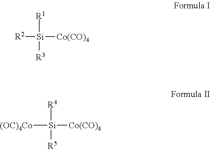
wherein each of R1, R2, R3, R4, and R5 is independently selected from the group consisting of Hydrogen; a halogen; linear, cyclic or branched hydrocarbons; primary amino ligands (—NHR); and secondary amino ligands (—NRR′), with R and R′ independently being H, a linear, cyclic or branched hydrocarbon, or SiMe3 provided at least one of R1, R2, or R3 in Formula I and R4 or R5 in Formula II is an amino ligand.
2. The compound of claim 1 , wherein the Formula I compound includes one or two neutral adduct ligands selected from the group consisting of NMe3, NEt3, NiPr3, NMeEt2, NC5H5, OC4H8, Me2O, and Et2O.
3. The compound of claim 1 , wherein the compound has Formula I and is selected from the group consisting of (NMe2)3SiCo(CO)4, SiH(NMe2)2Co(CO)4, SiH2(NMe2)Co(CO)4, Si(NEt2)3Co(CO)4, SiH(NEt2)2Co(CO)4, SiH2(NEt2)Co(CO)4, Si(N-iPr2)3Co(CO)4, SiH(N-iPr2)2Co(CO)4, SiH2(N-iPr2)Co(CO)4, Si(NHtBu)3Co(CO)4, SiH(NHtBu)2Co(CO)4, SiH2(NHtBu)Co(CO)4, SiCl(NMe2)2Co(CO)4, SiMe(NMe2)2Co(CO)4, (CH2═CH)Si(Me)(NMe2)Co(CO)4, (CH2═CH)Si(Me)(NEt2)Co(CO)4, (CH2═CH)Si(Me)(N-iPr2)Co(CO)4, (CH2═CH)Si(NEt2)2Co(CO)4, and (NHSiMe3)Si(Me)(H)Co(CO)4.
4. The compound of claim 3 , wherein the compound is selected from the group consisting of SiH(NEt2)2Co(CO)4, Si(NMe2)3Co(CO)4, SiH2(NiPr2)Co(CO)4, and SiH(NHtBu)2Co(CO)4.
5. The compound of claim 1 , wherein the compound has Formula II and is selected from the group consisting of (CO)4CoSi(NMe2)2Co(CO)4, (CO)4CoSi(NEt2)2Co(CO)4, (CO)4CoSi(N-iPr2)2Co(CO)4, (CO)4CoSi(NMe2)(H)Co(CO)4, (CO)4CoSi(NEt2)(H)Co(CO)4, (CO)4CoSi(N-iPr2)(H)Co(CO)4, (CO)4CoSi(NHtBu)(H)Co(CO)4, (CO)4CoSi(NHSiMe3)(Me)Co(CO)4, (CO)4CoSi(NHSiMe3)(Et)Co(CO)4, (CO)4CoSi(NHSiMe3)(iPr)Co(CO)4, (CO)4CoSi(NHSiMe3)(tBu)Co(CO)4, (CO)4CoSi(CH═CH2)(NMe2)Co(CO)4, (CO)4CoSi(CH═CH2)(NEt2)Co(CO)4, (CO)4CoSi(CH═CH2)(N-iPr2)Co(CO)4, and (CO)4CoSi(CH═CH2)(NHtBu)Co(CO)4.
6. A method of depositing a cobalt-containing film, the method comprising:
introducing a cobalt-containing compound into a reactor having a substrate disposed therein, wherein the cobalt-containing compound has one of the formulae:

wherein each of R1, R2, R3, R4, and R5 is independently selected from the group consisting of Hydrogen; a halogen; linear, cyclic or branched hydrocarbons; primary amino ligands (—NHR); and secondary amino ligands (—NRR′), with R and R′ independently being H or a linear, cyclic or branched hydrocarbon, provided at least one of R1, R2, or R3 in Formula I and R4 or R5 in Formula II is an amino ligand;
depositing at least part of the cobalt-containing compound onto the substrate to form the cobalt-containing film.
7. The method of claim 6 , wherein the Formula I compound includes one or two neutral adduct ligands selected from the group consisting of NMe3, NEt3, NiPr3, NMeEt2, NC5H5, OC4H8, Me2O, and Et2O.
8. The method of claim 6 , wherein the cobalt containing compound has Formula I and is selected from the group consisting of (NMe2)3SiCo(CO)4, SiH(NMe2)2Co(CO)4, SiH2(NMe2)Co(CO)4, Si(NEt2)3Co(CO)4, SiH(NEt2)2Co(CO)4, SiH2(NEt2)Co(CO)4, Si(N-iPr2)3Co(CO)4, SiH(N-iPr2)2Co(CO)4, SiH2(N-iPr2)Co(CO)4, Si(NHtBu)3Co(CO)4, SiH(NHtBu)2Co(CO)4, SiH2(NHtBu)Co(CO)4, SiCl(NMe2)2Co(CO)4, SiMe(NMe2)2Co(CO)4, (CH2═CH)Si(Me)(NMe2)Co(CO)4, (CH2═CH)Si(Me)(NEt2)Co(CO)4, (CH2═CH)Si(Me)(N-iPr2)Co(CO)4, (CH2═CH)Si(NEt2)2Co(CO)4, and (NHSiMe3)Si(Me)(H)Co(CO)4.
9. The method of claim 8 , wherein the cobalt containing compound is selected from the group consisting of SiH(NEt2)2Co(CO)4, Si(NMe2)3Co(CO)4, SiH2(NiPr2)Co(CO)4, and SiH(NHtBu)2Co(CO)4.
10. The method of claim 6 , wherein the cobalt containing compound has Formula II and is selected from the group consisting of (CO)4CoSi(NMe2)2Co(CO)4, (CO)4CoSi(NEt2)2Co(CO)4, (CO)4CoSi(N-iPr2)2Co(CO)4, (CO)4CoSi(NMe2)(H)Co(CO)4, (CO)4CoSi(NEt2)(H)Co(CO)4, (CO)4CoSi(N-iPr2)(H)Co(CO)4, (CO)4CoSi(NHtBu)(H)Co(CO)4, (CO)4CoSi(NHSiMe3)(Me)Co(CO)4, (CO)4CoSi(NHSiMe3)(Et)Co(CO)4, (CO)4CoSi(NHSiMe3)(iPr)Co(CO)4, (CO)4CoSi(NHSiMe3)(tBu)Co(CO)4, (CO)4CoSi(CH═CH2)(NMe2)Co(CO)4, (CO)4CoSi(CH═CH2)(NEt2)Co(CO)4, (CO)4CoSi(CH═CH2)(N-iPr2)Co(CO)4, and (CO)4CoSi(CH═CH2)(NHtBu)Co(CO)4.
11. The method of claim 6 , wherein the depositing step is selected from the group consisting of chemical vapor deposition (CVD), atomic layer deposition (ALD), plasma enhanced chemical vapor deposition (PECVD), plasma enhanced atomic layer deposition (PEALD), pulsed chemical vapor deposition (PCVD), low pressure chemical vapor deposition (LPCVD), sub-atmospheric chemical vapor deposition (SACVD), atmospheric pressure chemical vapor deposition (APCVD), spatial ALD, radicals incorporated deposition, super critical fluid deposition, and combinations thereof.
12. The method of claim 6 , wherein the method is performed at a temperature between about 20° C. and about 800° C., preferably between about 25° C. and about 600° C.
13. The method of claim 6 , wherein the reactor has a pressure between approximately 0.1 Pa and approximately 105 Pa, preferably between approximately 2.5 Pa and approximately 103 Pa.
14. The method of claim 6 , wherein the cobalt-containing film is selected from the group consisting of pure cobalt, cobalt nitride(CoN), cobalt silicide (CoSi), cobalt silicide nitride (CoSiN), and cobalt oxide(CoO).
15. The method of claim 6 , further comprising introducing a reaction gas into the reactor at the same time or at an alternate time as the introduction of the cobalt-containing compound.
16. The method of claim 15 , wherein the reaction gas is a reducing agent selected from the group consisting of N2, H2, NH3, SiH4, Si2H6, Si3H8, (Me)2SiH2, (C2H5)2SiH2, (CH3)3SiH, (C2H5)3SiH, [N(C2H5)2]2SiH2, N(CH3)3, N(C2H5)3, (SiMe3)2NH, (CH3)HNNH2, (CH3)2NNH2, phenyl hydrazine, B2H6, (SiH3)3N, radical species of these reducing agents, and mixtures of these reducing agents.
17. The method of claim 15 , wherein the reaction gas is an oxidizing reagent selected from the group consisting of O2, O3, H2O, H2O2, NO, NO2, acetic acid, radical species of these oxidizing agents, and mixtures of these oxidizing agents.
18. The compound of claim 3 , wherein the compound is (NMe2)3SiCo(CO)4.
19. The compound of claim 3 , wherein the compound is SiH(NEt2)2Co(CO)4.
20. The compound of claim 10 , wherein the compound is (CO)4CoSi(NEt2)2Co(CO)4.
Priority Applications (1)
| Application Number | Priority Date | Filing Date | Title |
|---|---|---|---|
| US14/765,098 US9790247B2 (en) | 2013-01-31 | 2014-01-31 | Cobalt-containing compounds, their synthesis, and use in cobalt-containing film deposition |
Applications Claiming Priority (3)
| Application Number | Priority Date | Filing Date | Title |
|---|---|---|---|
| US201361759138P | 2013-01-31 | 2013-01-31 | |
| US14/765,098 US9790247B2 (en) | 2013-01-31 | 2014-01-31 | Cobalt-containing compounds, their synthesis, and use in cobalt-containing film deposition |
| PCT/IB2014/058711 WO2014118747A1 (en) | 2013-01-31 | 2014-01-31 | Cobalt-containing compounds, their synthesis, and use in cobalt-containing film deposition |
Publications (2)
| Publication Number | Publication Date |
|---|---|
| US20150368282A1 US20150368282A1 (en) | 2015-12-24 |
| US9790247B2 true US9790247B2 (en) | 2017-10-17 |
Family
ID=51261538
Family Applications (1)
| Application Number | Title | Priority Date | Filing Date |
|---|---|---|---|
| US14/765,098 Active 2034-05-14 US9790247B2 (en) | 2013-01-31 | 2014-01-31 | Cobalt-containing compounds, their synthesis, and use in cobalt-containing film deposition |
Country Status (4)
| Country | Link |
|---|---|
| US (1) | US9790247B2 (en) |
| JP (1) | JP2016513085A (en) |
| KR (1) | KR102209476B1 (en) |
| WO (1) | WO2014118747A1 (en) |
Families Citing this family (3)
| Publication number | Priority date | Publication date | Assignee | Title |
|---|---|---|---|---|
| US9719167B2 (en) * | 2015-12-31 | 2017-08-01 | L'Air Liquide, Société Anonyme pour l'Etude et l'Exploitation des Procédés Georges Claude | Cobalt-containing film forming compositions, their synthesis, and use in film deposition |
| JP2019064950A (en) * | 2017-09-29 | 2019-04-25 | 国立大学法人九州大学 | Cobalt complex, manufacturing method therefor, and catalyst for hydrosilylation reaction |
| KR20200126011A (en) * | 2018-03-26 | 2020-11-05 | 램 리써치 코포레이션 | Intermediate layer for metal interconnect layer |
Citations (2)
| Publication number | Priority date | Publication date | Assignee | Title |
|---|---|---|---|---|
| US6346477B1 (en) | 2001-01-09 | 2002-02-12 | Research Foundation Of Suny - New York | Method of interlayer mediated epitaxy of cobalt silicide from low temperature chemical vapor deposition of cobalt |
| JP2010084215A (en) | 2008-10-02 | 2010-04-15 | Jsr Corp | Method for forming cobalt film |
Family Cites Families (2)
| Publication number | Priority date | Publication date | Assignee | Title |
|---|---|---|---|---|
| US7064224B1 (en) | 2005-02-04 | 2006-06-20 | Air Products And Chemicals, Inc. | Organometallic complexes and their use as precursors to deposit metal films |
| JP2006328526A (en) | 2005-04-27 | 2006-12-07 | Jsr Corp | Method for depositing metallic film |
-
2014
- 2014-01-31 JP JP2015555836A patent/JP2016513085A/en active Pending
- 2014-01-31 US US14/765,098 patent/US9790247B2/en active Active
- 2014-01-31 KR KR1020157023399A patent/KR102209476B1/en active IP Right Grant
- 2014-01-31 WO PCT/IB2014/058711 patent/WO2014118747A1/en active Application Filing
Patent Citations (2)
| Publication number | Priority date | Publication date | Assignee | Title |
|---|---|---|---|---|
| US6346477B1 (en) | 2001-01-09 | 2002-02-12 | Research Foundation Of Suny - New York | Method of interlayer mediated epitaxy of cobalt silicide from low temperature chemical vapor deposition of cobalt |
| JP2010084215A (en) | 2008-10-02 | 2010-04-15 | Jsr Corp | Method for forming cobalt film |
Non-Patent Citations (30)
| Title |
|---|
| Abraham, K.M. et al., "Synthesis of heteropolymetallic silanes," Inorganic Chemistry, 1973, vol. 12, No. 1, 2850-2856. |
| Almond, M.J., "Short-lived molecules," Angew, Chem. 103 (1991) No. 8, 1063. |
| Aylett, B.J. et al., "Chemical vapor deposition of metal silicides from organometallic compounds with silicon-metal bonds," Vacuum, 1985, vol. 35, Nos. 10-11, 435-439. |
| Baay, Y.L. et al, "Synthesis and properties of trimethylsilyl cobalt tetracarbonyl and related compounds," Inorg. Nucl. Chem. Letters, 1967, vol. 3, 159-161. |
| Baay, Y.L. et al., "Trimethyl- and trichlorosilylcobalt tetracarbonyls and the hydrosilation of ethylene," Inorganic Chemistry, vol. 8, No. 4, Apr. 1969, 986-994. |
| Begum, R et al., "Synthesis, reaction and thermal decomposition of a silicon-cobalt bonded compound," Journal of Bangladesh Academy of Sciences, 1993, vol. 17, No. 2, 201-205. |
| Bradley, G.F. et al., "Reaction of octacarbonyldicobalt with organo-silanes, -germanes, and -stannanes: Formation, properties, and vibrational spectra of trimethylgermyltetracarbonylcobalt and related complexes," Journal of the Chemical Society, Dalton Transactions: Inorganic Chemistry, 1974, vol. 3, 264-269. |
| Braunstein, P. et al., "New mono- and polynuclear iron silylene and stannylene complexes," Organometallics, 2001, vol. 20, No. 4, 627-633. |
| Cerveau, G. et al., "Cleavage of silicon- and germanium-transition metal bonds. Dependence of the stereochemistry on the nature of the ligands and the geometry of complexes," Journal of Organometallic Chemistry, 1982, vol. 236, No. 1, 33-52. |
| Chatani, N. et al., "A new entry to pi-allylcobalt tricarbonyls using (CH3)3SiCo(CO)4," Tetrahedron Letters, 1983, vol. 24, No. 50, 5649-5652. |
| Chatani, N. et al., 'Cobalt carbonyl catalyzed reactions of esters and lactones with hydrosilane and carbon monoxide. A novel synthetic method for the introduction of the siloxymethylidene group, J. Am. Chem. Soc., 1986, vol. 108, 7361-7373. |
| Cutler, A.R., "Selective transformation of carbonyl ligands to organic molecules," Progress Report for Period Sep. 1, 1989-Nov. 14, 1992, prepared for the U.S. Department of Energy on May 12, 1992, 23 pages. |
| Emeleus, H.J., "B. Transition metal derivatives," Advances in Inorganic Chemistry and Radiochemistry, 1982, 6 pages. |
| Gleizes, A.N., "MOCVD of chalcogenides, pnictides, and heterometallic compounds from single-source molecule precursors," Chemical Vapor Deposition, 2000, vol. 6, No. 4, 155-173. |
| Gusbeth, P. et al., "μ3-Silidyne heterometal clusters," Chemische Berichte, 1985, vol. 118, No. 3, 1143-1153. |
| Ingle, W.M. et al., "Cobalt to oxygen migration of the trimethylsilyl group in trimethylsilylcobalt tetracarbonyl," Journal of the Chemical Society, 1973, vol. 14, 497-498. |
| International Search Report and Written Opinion for corresponding PCT/IB2014/058711, Apr. 28, 2014. |
| International Search Report and Written Opinion for related PCT/IB2014/058712, Apr. 28, 2014. |
| Kreisz, J. et al., "Reaction of silylcobalt tetracarbonyls with oxiranes. Kinetics and mechanism," Journal of Organometallic Chemistry, 1993, vol. 451, Nos. 1-2, 53-57. |
| Morrison, D.L. et al., "13. Tricholor-, trimethyl-, and trifluorosilylcobalt tetracarbonyl," Inorganic Synthesis, 1971, vol. 13, 65-73. |
| Prokop, J. et al., "nm-Co2Si, CoSi and CoSi2 silicide films from the single source precursor CoSiCl3(CO)4 in the presences of SiH4 ," Thin Solid Films, 2000, vol. 359, 39-45. |
| Reichel, C.L. et al., "Photochemistry of cobalt carbonyl complexes having a cobalt-silicon bond and its importance in activation of catalysis," lnorg. Chem., 1980, vol. 19, 3858-3860. |
| Safiullah, S. et al., "Synthesis and characterization of complexes Me2Si[Co(CO)3]2 (dppe)," Journal of the Bangladesh Chemical Society, 1996, vol. 9, No. 1, 117-120. |
| Schmid, G. et al., "Silylene-metal complexes. 4. Base-stabilized silyleneiron complexes," Angewandte Chemie International Edition, 1977, vol. 16, No. 11, 785-786. |
| Schmitt, A.L., et al., "Synthesis and applications of metal silicide naowires," Journal of Materials Chemistry, 2010, 20, 223-235. |
| Sisak, A. et al., "Formation and multinuclear magnetic resonance investigation of silylammonium tetracarbonylcobaltate contact ion pairs," Central European Journal of Chemistry, 2006, 4(2), 299-316. |
| Sommer, L.H. et al., "Stereochemistry of asymmetric silicon. XV. Stereospecific hydrosilation and exchange reactions of R3Si*H(D) catalyzed by Group VIII metal centers," Journal of the American Chemical Society, 1969, vol. 91, No. 25, 7051-7061. |
| Street et al. "Silylation of Coordinate Dinitrogen by Silycobalt Complexes. Preparation of a New Series of Silyldiazenido and Silylhydrazido(2-) complexes of Molybdenum and Tungsten". Chemistry Letters,1991,383-386. * |
| Street, A.C. et al., 'Preparation and properties of molybdenum and tungsten dinitrogen complexes. 31. Silylation of coordinated dinitrogen by silylocobalt complexes. Preparation of a new series of silyldiazenido and silylhydrazido (2-) complexes of molybdenum and tungsten, Chemstry Letters, 1991, No. 3, 383-6, as received from JP receiving Office for International Search Report for related PCT/IB2014/058712. |
| Zhao et al. "The formation mechanism of cobalt silicide on silica from Co(SiCl3)(CO)4 by in situ Fourier transform infrared spectroscopy". Phys. Chem. Chem. Phys., 2011, 13, 9432-9438. * |
Also Published As
| Publication number | Publication date |
|---|---|
| US20150368282A1 (en) | 2015-12-24 |
| KR20150113114A (en) | 2015-10-07 |
| WO2014118747A1 (en) | 2014-08-07 |
| JP2016513085A (en) | 2016-05-12 |
| KR102209476B1 (en) | 2021-01-28 |
Similar Documents
| Publication | Publication Date | Title |
|---|---|---|
| US11549182B2 (en) | Group 6 transition metal-containing compounds for vapor deposition of group 6 transition metal-containing films | |
| US9938303B2 (en) | Organosilane precursors for ALD/CVD silicon-containing film applications | |
| US20160002786A1 (en) | Bis(alkylimido)-bis(alkylamido)molybdenum molecules for deposition of molybdenum-containing films | |
| US10106887B2 (en) | Group 5 transition metal-containing compounds for vapor deposition of group 5 transition metal-containing films | |
| US10309010B2 (en) | Cobalt-containing compounds, their synthesis, and use in cobalt-containing film deposition | |
| US10023462B2 (en) | Niobium-Nitride film forming compositions and vapor deposition of Niobium-Nitride films | |
| US20120308739A1 (en) | Methods for deposition of alkaline earth metal fluoride films | |
| US9382268B1 (en) | Sulfur containing organosilane precursors for ALD/CVD silicon-containing film applications | |
| US20170018425A1 (en) | Heteroleptic diazadienyl group 4 transition metal-containing compounds for vapor deposition of group 4 transition metal-containing films | |
| US9790247B2 (en) | Cobalt-containing compounds, their synthesis, and use in cobalt-containing film deposition | |
| WO2014118751A1 (en) | Manganese-containing compounds, their synthesis, and use in manganese-containing film deposition | |
| WO2014118750A1 (en) | Manganese-containing compounds, their synthesis, and use in manganese-containing film deposition | |
| US20160032454A1 (en) | Bis(alkylimido)-bis(alkylamido)tungsten molecules for deposition of tungsten-containing films | |
| WO2016094711A2 (en) | Organosilane precursors for ald/cvd silicon-containing film applications and methods of using the same |
Legal Events
| Date | Code | Title | Description |
|---|---|---|---|
| AS | Assignment |
Owner name: L'AIR LIQUIDE, SOCIETE ANONYME POUR L'ETUDE ET L'E Free format text: ASSIGNMENT OF ASSIGNORS INTEREST;ASSIGNORS:GATINEAU, SATOKO;KO, CHANGHEE;REEL/FRAME:036581/0516 Effective date: 20130517 |
|
| STCF | Information on status: patent grant |
Free format text: PATENTED CASE |
|
| MAFP | Maintenance fee payment |
Free format text: PAYMENT OF MAINTENANCE FEE, 4TH YEAR, LARGE ENTITY (ORIGINAL EVENT CODE: M1551); ENTITY STATUS OF PATENT OWNER: LARGE ENTITY Year of fee payment: 4 |