US9781057B1 - Deadlock avoidance techniques - Google Patents
Deadlock avoidance techniques Download PDFInfo
- Publication number
- US9781057B1 US9781057B1 US13/923,427 US201313923427A US9781057B1 US 9781057 B1 US9781057 B1 US 9781057B1 US 201313923427 A US201313923427 A US 201313923427A US 9781057 B1 US9781057 B1 US 9781057B1
- Authority
- US
- United States
- Prior art keywords
- resource
- request
- consumer
- pools
- common
- Prior art date
- Legal status (The legal status is an assumption and is not a legal conclusion. Google has not performed a legal analysis and makes no representation as to the accuracy of the status listed.)
- Active, expires
Links
Images


Classifications
-
- G—PHYSICS
- G06—COMPUTING; CALCULATING OR COUNTING
- G06F—ELECTRIC DIGITAL DATA PROCESSING
- G06F9/00—Arrangements for program control, e.g. control units
- G06F9/06—Arrangements for program control, e.g. control units using stored programs, i.e. using an internal store of processing equipment to receive or retain programs
- G06F9/46—Multiprogramming arrangements
- G06F9/52—Program synchronisation; Mutual exclusion, e.g. by means of semaphores
- G06F9/524—Deadlock detection or avoidance
-
- H—ELECTRICITY
- H04—ELECTRIC COMMUNICATION TECHNIQUE
- H04L—TRANSMISSION OF DIGITAL INFORMATION, e.g. TELEGRAPHIC COMMUNICATION
- H04L47/00—Traffic control in data switching networks
- H04L47/70—Admission control; Resource allocation
- H04L47/80—Actions related to the user profile or the type of traffic
- H04L47/805—QOS or priority aware
-
- G—PHYSICS
- G06—COMPUTING; CALCULATING OR COUNTING
- G06F—ELECTRIC DIGITAL DATA PROCESSING
- G06F2209/00—Indexing scheme relating to G06F9/00
- G06F2209/50—Indexing scheme relating to G06F9/50
- G06F2209/5011—Pool
Definitions
- This application generally relates to techniques for use in connection with deadlock avoidance.
- Computer systems may include different resources used by one or more host processors. Resources and host processors in a computer system may be interconnected by one or more communication connections. These resources may include, for example, data storage devices such as those included in the data storage systems manufactured by EMC Corporation. These data storage systems may be coupled to one or more host processors and provide storage services to each host processor. Multiple data storage systems from one or more different vendors may be connected and may provide common data storage for one or more host processors in a computer system.
- a host processor may perform a variety of data processing tasks and operations using the data storage system. For example, a host processor may perform basic system I/O operations in connection with data requests, such as data read and write operations.
- Host processor systems may store and retrieve data using a storage system containing a plurality of host interface units, disk drives, and disk interface units. Such storage systems are provided, for example, by EMC Corporation of Hopkinton, Mass.
- the host systems access the storage system through a plurality of channels provided therewith.
- Host systems provide data and access control information through the channels to the storage system and the storage system provides data to the host systems also through the channels.
- the host systems do not address the disk drives of the storage system directly, but rather, access what appears to the host systems as a plurality of logical disk units, logical devices, or logical volumes (LVs).
- the logical disk units may or may not correspond to the actual disk drives. Allowing multiple host systems to access the storage system allows the host systems to share data stored therein.
- the system may be characterized as being in deadlock.
- deadlock it may be desirable to utilize techniques to avoid, detect, and/or prevent deadlock from occurring.
- a method of avoiding deadlock comprising: assigning a plurality of consumers a plurality of priority levels, wherein each of the plurality of consumers is assigned one of the plurality of priority levels denoting a number of resource allocation requests that have been currently granted to said each consumer, wherein the one priority level is incremented each time a resource allocation request for the consumer is granted; providing a set of one or more common resource pools and a reserved resource pool, wherein the set of one or more common resource pools are used in granting resource requests made by any of the plurality of consumers and wherein the reserved resource pool is used in granting resource requests made by a single one of the plurality of consumers for a lifetime of the single consumer; maintaining a wait list of pending resource requests made by one or more of the plurality of consumers; determining that no allocated resources of the set of one or more common pools have been released for at least a threshold amount of time and that there is at least one request on the wait list; in response to determining that no allocated resources of the set of one
- the method may include receiving a third resource request from a second of the plurality of consumers different from the first consumer; determining whether there are sufficient resources in the set of one or more common pools to grant the third resource request; and responsive to determining that there are sufficient resources in the set of one or more common pools to grant the third resource request, granting the third resource request of the second consumer using the set of one or more common pools.
- the method may include adding the third request to the wait list responsive to determining that there are insufficient resources in the set of one or more common pools to grant the third resource request.
- the reserved pool may have an amount of resources determined as an upper bound representing a maximum cumulative resource amount potentially required by a consumer a during a lifetime of a consumer.
- the one or more criteria may include determining which pending resource request in the wait list has a highest one of the priority levels of all pending resource requests in the wait list. If there are multiple pending resource requests in the wait list having a same highest priority level, one of the multiple pending resource requests may be selected having a largest amount of currently allocated memory with respect to the multiple pending resource requests.
- resources assigned to, or used by, the first consumer may be released whereby any resources allocated to the first consumer from the set of one or more common pools are released and whereby the reserved pool is available for reassignment to another one of the plurality of consumers for exclusive use by the another one consumer.
- Each of the plurality of consumers may be an I/O operation having processing performed to service the I/O operation.
- a computer readable medium comprising code stored thereon for avoiding deadlock
- the computer readable medium comprising code stored thereon for: assigning a plurality of consumers a plurality of priority levels, wherein each of the plurality of consumers is assigned one of the plurality of priority levels denoting a number of resource allocation requests that have been currently granted to said each consumer, wherein the one priority level is incremented each time a resource allocation request for the consumer is granted; providing a set of one or more common resource pools and a reserved resource pool, wherein the set of one or more common resource pools are used in granting resource requests made by any of the plurality of consumers and wherein the reserved resource pool is used in granting resource requests made by a single one of the plurality of consumers for a lifetime of the single consumer; maintaining a wait list of pending resource requests made by one or more of the plurality of consumers; determining that no allocated resources of the set of one or more common pools have been released for at least a threshold amount of time and that there is at least one
- the computer readable medium may further comprise code for granting the first pending resource request using the reserved pool.
- the computer readable medium may include code for receiving a second resource request from the first consumer; determining whether there are sufficient resources in the set of one or more common pools to grant the second resource request; and responsive to determining that there are insufficient resources in the set of one or more common pools to grant the second resource request, granting the second resource request of the first consumer using the reserved pool.
- the computer readable medium may include code for granting the second resource request using the set of one or more common pools responsive to determining that there are sufficient resources in the set of one or more common pools to grant the second resource request.
- the computer readable medium may include code for receiving a third resource request from a second of the plurality of consumers different from the first consumer; determining whether there are sufficient resources in the set of one or more common pools to grant the third resource request; responsive to determining that there are sufficient resources in the set of one or more common pools to grant the third resource request, granting the third resource request of the second consumer using the set of one or more common pools; responsive to determining that there are insufficient resources in the set of one or more common pools to grant the third resource request, adding the third request to the wait list.
- the reserved pool may have an amount of resources determined as an upper bound representing a maximum cumulative resource amount potentially required by a consumer a during a lifetime of a consumer.
- the one or more criteria may include determining which pending resource request in the wait list has a highest one of the priority levels of all pending resource requests in the wait list, and wherein, if there are multiple pending resource requests in the wait list having a same highest priority level, one of the multiple pending resource requests is selected having a largest amount of currently allocated memory with respect to the multiple pending resource requests.
- FIG. 1 is an example of an embodiments of a system that may utilize the techniques described herein;
- FIG. 2 is an example illustrating details of a data storage system in accordance with techniques herein;
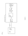
- FIG. 3 is an example illustrating a request that may be issued from a host to the data storage system in an embodiment in accordance with techniques herein;
- FIGS. 4 and 5 are examples illustrating objects as may be included in an object model or topology in an embodiment in accordance with techniques herein;
- FIG. 6 is an example of memory pools and a list of pending allocation requests that may be used in an embodiment in accordance with techniques herein;
- FIGS. 7-10 are flowcharts of processing steps that may be performed in an embodiment in accordance with techniques herein.
- the system 10 includes one or more data storage systems 12 connected to server or host systems 14 a - 14 n through communication medium 18 .
- the system 10 also includes a management system 16 connected to one or more data storage systems 12 through communication medium 2 .
- the management system 16 , and the N servers or hosts 14 a - 14 n may access the data storage systems 12 , for example, in performing input/output (I/O) operations, data requests, and other operations.
- the communication medium 18 may be any one or more of a variety of networks or other type of communication connections as known to those skilled in the art.
- Each of the communication mediums 18 and 2 may be a network connection, bus, and/or other type of data link, such as a hardwire or other connections known in the art.
- the communication medium 18 may be the Internet, an intranet, network or other wireless or other hardwired connection(s) by which the host systems 14 a - 14 n may access and communicate with the data storage systems 12 , and may also communicate with other components (not shown) that may be included in the computer system 10 .
- the communication medium 2 may be a LAN connection and the communication medium 18 may be an iSCSI or Fibre Channel connection.
- Each of the host systems 14 a - 14 n and the data storage systems 12 included in the system 10 may be connected to the communication medium 18 by any one of a variety of connections as may be provided and supported in accordance with the type of communication medium 18 .
- the management system 16 may be connected to the communication medium 2 by any one of variety of connections in accordance with the type of communication medium 2 .
- the processors included in the host computer systems 14 a - 14 n and management system 16 may be any one of a variety of proprietary or commercially available single or multi-processor system, such as an Intel-based processor, or other type of commercially available processor able to support traffic in accordance with each particular embodiment and application.
- Each of the host computers 14 a - 14 n , the management system 16 and data storage systems may all be located at the same physical site, or, alternatively, may also be located in different physical locations.
- communication mediums 18 and 2 a variety of different communication protocols may be used such as SCSI, Fibre Channel, iSCSI, and the like.
- Some or all of the connections by which the hosts, management system, and data storage system may be connected to their respective communication medium may pass through other communication devices, such as switching equipment that may exist such as a phone line, a repeater, a multiplexer or even a satellite.
- the hosts may communicate with the data storage systems over an iSCSI or a Fibre Channel connection and the management system may communicate with the data storage systems over a separate network connection using TCP/IP.
- FIG. 1 illustrates communications between the hosts and data storage systems being over a first connection, and communications between the management system and the data storage systems being over a second different connection, an embodiment may also use the same connection.
- the particular type and number of connections may vary in accordance with particulars of each embodiment.
- Each of the host computer systems may perform different types of data operations in accordance with different types of tasks.
- any one of the host computers 14 a - 14 n may issue a data request to the data storage systems 12 to perform a data operation.
- an application executing on one of the host computers 14 a - 14 n may perform a read or write operation resulting in one or more data requests to the data storage systems 12 .
- the management system 16 may be used in connection with management of the data storage systems 12 .
- the management system 16 may include hardware and/or software components.
- the management system 16 may include one or more computer processors connected to one or more I/O devices such as, for example, a display or other output device, and an input device such as, for example, a keyboard, mouse, and the like.
- a data storage system manager may, for example, view information about a current storage volume configuration on a display device of the management system 16 , provision data storage system resources, and the like.
- the data storage systems 12 may include one or more data storage systems such as one or more of the data storage systems, such as data storage arrays, offered by EMC Corporation of Hopkinton, Mass. Each of the data storage systems may include one or more data storage devices 13 a - 13 n , such as disks. One or more data storage systems may be manufactured by one or more different vendors. Each of the data storage systems included in 12 may be inter-connected (not shown). Additionally, the data storage systems may also be connected to the host systems through any one or more communication connections that may vary with each particular embodiment and device in accordance with the different protocols used in a particular embodiment.
- the type of communication connection used may vary with certain system parameters and requirements, such as those related to bandwidth and throughput required in accordance with a rate of I/O requests as may be issued by the host computer systems, for example, to the data storage systems 12 .
- each of the data storage systems may operate stand-alone, or may also be included as part of a storage area network (SAN) that includes, for example, other components such as other data storage systems.
- SAN storage area network
- Each of the data storage systems may include a plurality of disk devices or volumes 13 a - 13 n .
- the particular data storage systems and examples as described herein for purposes of illustration should not be construed as a limitation. Other types of commercially available data storage systems, as well as processors and hardware controlling access to these particular devices, may also be included in an embodiment.
- each of the data storage systems and management system 16 may include code thereon for performing the techniques as described herein.
- Servers or host systems such as 14 a - 14 n , provide data and access control information through channels to the storage systems, and the storage systems may also provide data to the host systems also through the channels.
- the host systems may not address the disk drives of the storage systems directly, but rather access to data may be provided to one or more host systems from what the host systems view as a plurality of logical devices or logical volumes (LVs).
- the LVs may or may not correspond to the actual disk drives.
- one or more LVs may reside on a single physical disk drive. Data in a single storage system may be accessed by multiple hosts allowing the hosts to share the data residing therein.
- An LV or LUN (logical unit number) may be used to refer to the foregoing logically defined devices or volumes.
- the data storage system 12 may be a data storage array, such as a CLARiiON® data storage array or a VNX® data storage array by EMC Corporation of Hopkinton, Mass., including a plurality of data storage devices 16 a - 16 n and two storage processors 17 a , 17 b .
- the storage processors (SPs) 17 a , 17 b may be computer processing units included in the data storage system for processing requests and commands.
- an embodiment of the data storage system may include multiple storage processors including more than two storage processors or main CPUs as described.
- the CLARiiON® data storage system and the VNX® data storage systems mentioned above may each include two storage processors 17 a , 17 b for performing processing in connection with servicing requests. Additionally, the two storage processors 17 a , 17 b may be used in connection with failover processing when communicating with the management system 16 .
- Client software on the management system 16 may be used in connection with performing data storage system management by issuing commands to the data storage system 12 and/or receiving responses from the data storage system 12 over connection 2 .
- the management system 16 may be a laptop or desk top computer system.
- FIG. 2 shown is an example of an embodiment of the data storage system 12 that may be included in the system 10 of FIG. 1 .
- the data storage system 12 of FIG. 2 includes one or more data storage systems 20 a - 20 n as may be manufactured by one or more different vendors.
- Each of the data storage systems 20 a - 20 n may be a data storage array inter-connected (not shown) to other data storage array(s).
- the data storage systems may also be connected to the host systems through any one or more communication connections 31 .
- reference is made to the more detailed view of element 20 a It should be noted that a similar more detailed description may also apply to any one or more of the other elements, such as 20 n , but have been omitted for simplicity of explanation.
- Each of the data storage systems may include a plurality of storage devices such as disk devices or volumes included in an arrangement 24 consisting of n rows of disks or more generally, data storage devices, 24 a - 24 n .
- each row of disks may be connected to a disk adapter (“DA”) or director responsible for the backend management of operations to and from a portion of the disks 24 .
- DA disk adapter
- a single DA such as 23 a
- a backend DA may also be referred to as a disk controller.
- the DA may performed operations such as reading data from, and writing data to, the physical devices which are serviced by the DA.
- the system 20 a may also include one or more storage processors 27 .
- Each of the storage processors 27 may be a CPU and an embodiment may include any number of such processors.
- the VNX® data storage system by EMC Corporation includes two storage processors.
- the system 20 a may also include one or more host adapters (“HAs”) or directors 21 a - 21 n .
- HAs host adapters
- Each of the HAs may be used to manage communications and data operations between one or more host systems and the global memory.
- the HA may be a Fibre Channel Adapter (FA) or other adapter which facilitates host communication.
- the HA communicates with a component of the host such as a host bus adapter (HBA).
- HBA host bus adapter
- directors may also be characterized as the different adapters, such as HAs (including FAs), DAs RAs and the like, as described herein.
- Components of the data storage system such as an HA, which may communicate with a host may also be referred to as front end components.
- components which may be characterized as backend components, communicate with a front end component.
- An example of a backend component is a DA.
- directors or adapters may be implemented as a processor, or, more generally, a component that includes the processor. Examples of directors are disk adapters (DAs), host adapters (HAs), and the like.
- One or more internal logical communication paths may exist between the DAs, the RAs, the HAs, and the memory 26 .
- An embodiment may use one or more internal busses and/or communication modules.
- the global memory portion 25 b may be used to facilitate data transfers and other communications between the DAs, HAs and RAs in a data storage system.
- the DAs 23 a - 23 n may perform data operations using a cache that may be included in the global memory 25 b , for example, in communications with other disk adapters or directors, and other components of the system 20 a .
- the other portion 25 a is that portion of memory that may be used in connection with other designations that may vary in accordance with each embodiment.
- the RA may be hardware including a processor used to facilitate communication between data storage systems, such as between two of the same or different types of data storage systems.
- a data storage system may include two SPs (also referred to as main processors or storage system processors A and B) although a data storage system and techniques herein may be used in an embodiment in which the data storage system includes more than two storage processors as mentioned above.
- the two SPs 27 may control the operation of the data storage system.
- the processors may be configured to process requests as may be received from the hosts, other data storage systems, management system, and other components connected thereto. Each of the SPs may process received requests and operate independently and concurrently with respect to the other processor. With respect to data storage management requests, operations, and the like, as may be received from a client, such as the management system 16 of FIG. 1 in connection with the techniques herein, the client may interact with a designated one of the two SPs. Upon the occurrence of failure of one the SPs, the other remaining SP may handle all processing typically performed by both SPs.
- I/O operations performed in a data storage system may include I/O operations which are received by the data storage system from an external client, such as a host.
- the single host I/O operation such as for a write operation, may result in more than one write operation to one or more physical drives on the data storage system. For example, if the host write is directed to a logical device, such as a LUN, having storage provisioned from a RAID group having a RAID-1 mirroring configuration with two physical drives, then a single front end or host I/O to the LUN results in two back-end physical device writes to each of the two mirrored physical devices of the storage system comprising the RAID group.
- a logical device such as a LUN
- the example 100 includes a simplified view of components of a system as described above.
- the example 100 includes a host 110 with an HBA 112 .
- the host 110 communicates with data storage system 120 over connection 114 .
- Connection 114 may be, for example, a network connection between the HBA 112 and a front end adapter 122 of the data storage system 120 .
- a front end adapter 122 may be, for example, an FA.
- the data storage system 120 also includes a cache 124 , a DA or storage controller 126 and one or more physical storage devices 128 (e.g., rotating disks or solid state devices (SSDs) such as a flash drive).
- the host 110 may issue an I/O operation to the data storage system over connection 114 .
- the host may issue a write operation to write data to a portion of storage device 128 .
- the data of the write operation may first be stored in cache 124 and then destaged at a later point in time by DA 126 to the physical storage device 128 .
- the foregoing host write operation is an example of an I/O operation of the type described above issued by the client.
- the single client I/O operation may result in actually writing data to one or more storage devices depending on how the device to which the I/O is directed is configured.
- processing may first determine whether the data requested is already in cache 124 (thereby resulting in a cache hit or read hit). If the requested read data is in cache 124 , the data is retrieved from cache 124 and returned to the host 110 . Thus, a read resulting in a cache hit may be serviced without having to access the physical storage device 128 for the data. If the requested data is not in cache 124 , the data is retrieved by the DA 126 from the storage device 128 , stored in cache 124 , and then returned by the front end adapter 122 to the host 110 .
- each of the SPs 27 may have its own instance of a data model, such as a object model, that represents various logical and physical aspects of the data storage configuration.
- the data model may include objects representing physical and logical entities in the data storage system.
- objects may exist in the model representing the data storage system configuration whereby the objects may represent physical entities such as the physical drives (PDs) and logical entities such as a RAID Group, a LUN, and the like.
- Each PD may have a corresponding PDO (physical drive object).
- PDO provision drive object
- PVO provision drive object
- a PVO may be used to represent aspects of provisioned physical storage of a physical drive (as represented by its PDO associated with the PVO) such as for RAID groups (e.g. indicating that the PD is a member of a particular RAID group).
- the PVO may be used in connection with coordinating performing a firmware update of a PD associated with the PVO.
- the PD may not have yet been provisioned and configured into other logical entities, such as into RAID groups, LUNs, and the like, for use in storing client data.
- an object may have data fields corresponding to attributes describing the object and associated procedures or routines known as methods.
- a method may be invoked to perform an action or operation on an object.
- Objects may be instances of defined object classes. Objects and associated methods may be written using any suitable programming language such as, for example, C++ and Java.
- the example 250 includes a graph with nodes and edges between the nodes.
- the graph in this example forms a tree having a root node 252 at a first level, nodes 254 a - 254 c at a second level, nodes 256 a - 256 b at a third level, nodes 208 a - 258 e at a fourth level and leaf nodes 260 a - 260 e at a fifth level.
- the graph may be a representation of logical and/or physical components in the data storage system with the root node 252 corresponding to an aggregator or external interface node for the data storage system, or more specifically, an interface node to the data storage system.
- Each node in the graph other than the root node represents an object associated with a corresponding physical or logical entity in the data storage system.
- the leaf nodes at the fifth level correspond to objects associated with physical storage devices, such as rotating disk drives (e.g., Fibre channel drives, SATA drives) or SSDs (solid state storage devices such as comprising flash-based memory).
- Nodes at levels other than the first level (root node) and bottom most level (level 5 including leaf nodes 260 a - 260 e ) may correspond to, for example, RAID groups, drives or members of a RAID group, LUNs, and the like.
- nodes 254 a - 254 c correspond, respectively, to objects associated with LUNs 1-3
- nodes 256 a - 256 b correspond, respectively, to objects associated with RAID GROUPS 1 and 2
- nodes 258 a and 258 b correspond to PVOs associated with RAID drives or members of RAID GROUP 1
- nodes 258 c - 258 e correspond to PVOs associated with RAID drives or members of RAID GROUP 2
- nodes 260 a - 260 e correspond to physical device objects (PDOs) associated with physical storage devices (PDs) 270 a - e .
- PDO physical device objects
- Each PDO may be associated with a single PD
- each PDO may be associated with a single PVO.
- object 256 a may represent a mirroring configuration object such as for a RAID-1 configuration whereby PD 1 represented by PDO 260 a and PD2 represented by PDO 260 b are mirrors of each
- a path in the graph may correspond to an I/O path over which an I/O operation may be forwarded to a physical device (PD) for processing.
- PD physical device
- a host I/O operation directed to LUN 3 to write data may result in writing user data and/or parity information to a portion of PD5 forwarded along the path represented by nodes 252 , 254 c , 256 b , 258 e , 260 e .
- the foregoing may be a complete path from the root to a leaf node.
- An I/O operation may be forwarded along a path from a first node which is at a level M in the graph, M>1 (e.g., the root node is at level 1), to one of its descendant nodes in the graph, such as one of the leaf nodes or other nodes at a level>M in the graph.
- dashed lines denoted as A and B Portions of the graph above line A may represent those entities of the data storage system which are visible to the host or other external client. For example, the host may send I/O requests directed to one or more LUNs. The host may not have any knowledge regarding underlying RAID groups that may be included in an embodiment. Nodes below line A may correspond to entities known or exposed within the data storage system, but not to the host. Dashed line B represents the partitioning of the graph into nodes corresponding to physical and logical entities. Nodes above line B (other than the root) may correspond to logical entities (e.g., LUNs, RAID groups, RAID drives or members) of the data storage system. Nodes below line B may correspond to physical entities, such as physical storage devices, of the data storage system.
- logical entities e.g., LUNs, RAID groups, RAID drives or members
- an embodiment may utilize a topology of objects to represent a current configuration and state of the data storage system.
- An I/O operation may be represented by a I/O path in the object topology such as illustrated in FIG. 4 whereby the I/O operation processing may be characterized as traversing the I/O path in the object topology when servicing the I/O operation request.
- services such as a library of service routines, invoked at different levels in the object topology such as by methods of the objects in the path.
- memory may be allocated by each object in the runtime object stack at each level in the topology. For example, a method of each object in the object stack and/or service invoked may issue one or more memory allocation requests.
- the example 300 includes a generic representation of an object topology 310 that may represent the configuration and state of the data storage system at a point in time.
- the topology 310 is a more generalized or generic representation of objects from that such as illustrated in more detail in FIG. 4 .
- Element 320 may represent a services library of routines that may be invoked at different levels in a particular runtime object stack for an I/O request.
- the example 300 includes flow arrows 312 a - f generally representing possible runtime execution flow up between various objects in the topology when servicing I/O requests.
- flow arrows 314 a - c represent the possible runtime execution flow between the services library 320 and various objects at different levels in the topology 310 .
- arrow 314 b generally represents possible runtime execution flow between any of nodes B,C at level 2 in the object topology
- arrow 314 c generally represents the possible runtime execution flow between any of the leaf nodes D, E, F, G, and H at level 3 in the object topology.
- memory allocation requests may be made by code executed at various levels in the runtime object stack represented by a particular path in the object topology 310 . Additionally, memory allocation requests may be made at runtime by code from the services library 320 whereby a routine of the service library 320 may be invoked by objects, or more specifically a method thereof, at various levels of 310 as illustrated by any of 314 a - c.
- each I/O operation is associated with a priority level denoting a memory allocation priority.
- the priority level may be an integer greater than or equal to zero (0).
- the priority level associated with the I/O operation is increased.
- the priority level identifying the number of memory allocation requests that have been performed may denote a runtime level of progress of the I/O operation through the runtime I/O path whereby the runtime I/O path may be represented by the runtime object stack and associated services invoked during runtime.
- a first I/O operation having a first priority level that is higher than a second priority level associated with a second I/O operation represents that the first I/O operation has made more memory requests than the second I/O operation.
- the higher the priority level associated with an I/O operation the higher the probability that the I/O operation has more memory allocated than another I/O operation having a lower associated priority level. Processing of the higher priority I/O operation may be closer to completion (e.g., having progressed further along its runtime processing) than the I/O operation having a lower priority.
- An embodiment in accordance with techniques herein may have a set of one or more common memory pools from which memory is allocated in response to memory allocation requests in connection with processing I/O operations of any/all priority levels.
- the set of one or more common memory pools may include, for example, pools of memory each including memory portions of a particular size.
- a first pool in the common pool set may include portions of memory of a first size such as 1 ⁇ 2 megabyte
- a second pool in the common pool set may include portions of memory of a second size, such as 1 megabyte, and so on.
- a memory allocation request associated with processing an I/O operation of any priority level may obtain memory from one of the common memory pools based on the amount of memory requests.
- a request to allocate 1 ⁇ 2 megabyte of memory may obtain memory from the first pool rather than the second pool.
- the particular number of pools in the set of common pools and any associated memory allocation sizes may vary with embodiment.
- any suitable number, N, of common pools, where N is an integer ⁇ 1, may be utilized.
- an embodiment in accordance with techniques herein may use a reserved pool of memory.
- the reserved pool of memory may be assigned for use in connection with servicing a single I/O operation for the duration or “lifetime” of such processing (e.g., until the servicing of the I/O operation has completed).
- the size of the reserved pool may be represented by MAX denoting the maximum amount of memory that may be needed for processing any I/O request. In other words, MAX represents the largest possible upper bound to the cumulative amount of memory that may be allocated at any point in time when processing an I/O operation.
- an I/O request which is assigned sole usage of the reserved pool during its servicing lifetime is guaranteed to have a sufficient amount of memory to be able to complete whereby all memory allocation requests for processing the I/O request are made from the reserved pool.
- the size of the reserved pool may be characterized as the largest cumulative amount of memory that any I/O request will need to complete processing.
- a value, MAX may be determined by considering the maximum cumulative amount of memory that may be allocated when processing a single I/O through runtime processing during the lifetime of that I/O operation. For example, MAX may be determined by adding the most memory that can be allocated at each level in the runtime processing through the object stack and service library. To further illustrate, assume it is determined that at most 10 memory allocation requests can be made in connection with runtime processing for any I/O operation and that each of the 10 memory allocation requests has a largest possible size of 2 megabytes per request. In this case, MAX may be determined as 20 megabytes (e.g., 10 requests*2 megabytes) and the size of the reserved pool is 20 megabytes. In this manner, processing for any single I/O is guaranteed to have all memory allocation requests satisfied using the reserved pool.
- MAX may be determined by considering the maximum cumulative amount of memory that may be allocated when processing a single I/O through runtime processing during the lifetime of that I/O operation. For example, MAX may be determined by adding the most memory that can be allocated at
- an I/O operation has a runtime object stack as follows: 252 , 254 b , 256 b , 258 c , 260 c .
- the foregoing object stack is traversed and memory allocation requests may be made at various object levels. For example, at a first point in time processing for the I/O operation may be at object 256 b and a total of 2 memory allocation requests may be made so far in the runtime processing. The total memory allocated may be 5 megabytes at this first point in time.
- processing may be at object 258 c and a total of 3 memory allocation requests may be made so far in runtime processing whereby the total memory allocated may now be 5.5 megabytes.
- processing may be at object 260 c and a total of 4 memory allocation requests may be made so far in runtime processing whereby the total memory allocated may now be 6 megabytes.
- MAX the total cumulative amount of memory that can be allocated at any point in time is determined as MAX.
- the total amount of memory currently allocated at each point in time a request is granted may also be tracked and used in connection with techniques herein.
- the requests are granted by allocating memory from the set of one or more common pools. Additionally, memory may also be returned to the set of one or more common pools as allocated memory is no longer needed or freed in connection with servicing I/O requests. For example, once servicing an I/O operation completes, all memory allocated in connection with the I/O operation servicing may be returned to the set of one or more common pools for use in granting any subsequent memory allocation requests.
- the memory available for allocation from the set of one or more common pools may be exhausted or otherwise contain an insufficient amount of memory required to satisfy a request.
- a memory allocation request that cannot be granted from the set of one or more common pools may be placed on a wait list of pending memory allocation requests not yet granted.
- FIG. 6 shown is an example illustrating the memory pools and list of pending memory requests that may be used in an embodiment in accordance with techniques herein.
- the example 400 illustrates the pools and pending request list just described.
- Element 402 represents the set of one or more common pools of memory from which memory may be allocated to grant a memory allocation request when processing an I/O operation of any priority level.
- Element 404 represents the reserved pool of memory.
- Element 410 represents the wait list of pending memory allocation requests which have been issued but not yet granted due to insufficient memory in the set of one or more common pools 402 .
- the wait list 410 is illustrated as including entries 410 a - n each of which corresponds to a single pending memory allocation request made in connection with processing an associated I/O request.
- Element 412 illustrates in more detail information that may be included in entry 410 a . Although not explicitly illustrated in FIG. 6 , each element of the list 410 may include the detailed information as illustrated by 412 .
- Entry 410 a may include a priority level 412 a denoting the memory allocation priority level of the associated I/O operation for the pending request, a total amount of memory currently allocated 412 b , an allocation request size 412 c identifying the amount of memory requested, an I/O request ID identifying the I/O operation for which the pending memory allocation request was made, and possibly other information 412 e .
- the priority level 412 a is the current memory allocation priority level of the I/O operation for which the memory allocation request associated with entry 410 a has been made.
- the total amount of memory currently allocated 412 b represents the sum or cumulative amount of memory currently allocated for processing the associated I/O operation.
- the allocation request size 412 c denotes the amount of memory requested but which has not yet been allocated.
- the I/O request ID may be a unique identifier denoting the particular I/O operation being serviced for which the memory allocation request representing by the entry was made.
- the list 410 may be sorted or ordered from highest to lowest priority level as denoted by field 412 a of each entry of the list 410 . Additionally, the list 410 may be further sorted using the total amount of memory currently allocated 412 b as secondary criteria. For example, all entries of the same priority level may be further sorted in the list, from highest to lowest total amount of memory currently allocated 412 b .
- An embodiment may implement 402 , 404 and 410 using any suitable data structures known in the art.
- the list 110 may be implemented as a single or double linked list.
- one or more entries from the list 410 may be selected. Each such entry may be a pending request for which requested memory is now allocated from the memory just returned to the one or more common pools 402 .
- the list 410 may be examined to select a pending request for which memory is allocated whereby such selection may be made in accordance with one or more criteria.
- the criteria may include, for example, any of the priority level 412 a , the total amount of memory currently allocated 412 b and the allocation request size 412 c .
- the selected entry may represent the pending request on the list having the highest priority level in 412 a . If there are multiple requests having the same highest priority level in 412 a , the selected entry may additionally have the largest amount of memory currently allocated in 412 b of all such multiple entries having the same highest priority level. Additionally, the entry selected represents an I/O request that can be granted or satisfied using the available memory in the set of one or more common pools. In this manner, the information in the allocation request size 412 c may be utilized to ensure that the amount of memory requested as denoted in 412 c of the entry is currently available in the set of one or more common pools 402 .
- Processing may be performed to repeatedly select pending requests from the list 410 until either there are no further pending requests in the list 410 , or until there is insufficient memory in the set of one or more common pools 402 to grant any further pending requests from the list 410 .
- a pending request that can be granted is selected from the list 410 whereby the selecting request has a corresponding entry in the list 410 with the highest priority level in 412 a and, among all entries having the same highest priority level, the largest amount denoted in 412 b .
- the priority level 412 a may be characterized as first or primary criterion used to select an entry from the list 410 .
- the total amount of memory currently allocated 412 b may be characterized as secondary criterion used to select an entry from the list 410 whereby the value in 412 b may be used to select among entries having the same highest priority level.
- the I/O operation associated with the selected entry is assigned exclusive use of the reserved pool 404 for the duration or lifetime of the I/O operation (e.g., for the duration of processing the I/O operation).
- the I/O operation associated with the selected entry on the list 410 may be identified by the I/O request ID field 412 d of the selected entry.
- An embodiment may, for example, store the I/O operation assigned exclusive use of the reserved pool 404 in a location in memory, or otherwise use any suitable technique to denote the foregoing.
- the I/O operation assigned exclusive use of the reserved pool 404 may be characterized as “marked”. At a subsequent point in time, a second memory allocation request may be made in connection with processing the marked I/O operation.
- the requested memory is allocated from the set of one or more common pools 402 . Otherwise, if there is not a sufficient amount of memory in the set of one or more common pools 402 to grant the second memory request, then the requested memory is allocated from the reserved pool 404 . In this manner, a memory allocation request made during processing the marked I/O operation is always guaranteed to be granted without the request being placed on the list 410 . At a later point in time, processing for the marked I/O operation completes whereby resources utilized during such processing are freed and made available for other use.
- the resources freed include any memory from the set of one or more common pools 402 and the reserved pool 404 that had been allocated for use in processing the completed marked I/O operation.
- the reserved pool 404 is available for reassignment, as may be needed, for sole exclusive use by another I/O operation for its duration or lifetime.
- any memory returned to the set of one or more common pools 402 is also now available for use in granting any currently pending requests in the list and/or any subsequently received requests for memory.
- a single reserved pool 404 for a single marked I/O operation may be used in an embodiment. More generally, an embodiment in accordance with techniques herein may have any suitable number of reserved pools, each of the MAX size and each for exclusive used by a single marked I/O operation. Typically, an embodiment may select a small number of reserved pools and thus a small number of possible marked I/O operations.
- the foregoing describes an embodiment using techniques herein with an object-based topology and in connection with memory as the resource. More generally, techniques herein may be used in connection with other suitable non-object-based embodiments, with other resources other than memory, and in connection with other consumer entities besides I/O operation processing which consumes the resource. Techniques may be generally be used an embodiment with a defined process whereby the upper bound, MAX, of the resource usage during the processing may be determined. Consistent with the foregoing, other items described herein may also be accordingly generalized. For example, the set of one or more common pools and the reserved pool may be pools of a resource used in connection with resource requests by consumers of the resource. The assignment of the reserved resource pool to a single consumer may be for the lifetime of the consumer, or processing associated with the consumer entity.
- granting of the memory allocation request may be delayed (e.g., such as when place on the wait list) but may never be denied or not granted.
- an embodiment in accordance with techniques herein does not return a response indicating not granted or denied.
- the foregoing may be contrasted with a typical memory allocation request that returns a response immediately based on currently available memory. If at the time the request is made there is sufficient available memory, the request is granted. Otherwise, a response to the request may be returned indicating failure to grant the requested memory allocation.
- the memory allocation request is received which requests memory in connection with processing or servicing an I/O operation.
- the priority level of the I/O operation is incremented. As described above, the priority level is the memory allocation priority level that is increased each time there is a memory allocation request made on behalf of the associated I/O operation.
- a determined is made as to whether there is sufficient memory available in the set of one or more common pools to grant the current memory allocation request.
- step 506 evaluates to yes, control proceeds to step 514 where the requested memory is allocated from the set of one or more common pools. If step 506 evaluates to no, control proceeds to step 508 . At step 508 , a determination is made as to whether the I/O operation is “marked” as being associated with the reserved pool. If step 508 evaluates to no, control proceeds to step 510 to add the current request to the wait list of pending memory allocation requests. If step 508 evaluates to yes, control proceeds to step 512 to allocate memory for the current request from the reserved pool.
- step 702 allocated memory from the set of one or more common pools is now released thereby made available for reuse in servicing other memory allocation requests.
- Memory may be freed as in step 702 in response to an I/O operation completing whereby the I/O operation has been serviced.
- step 704 a determination is made as to whether there are any pending memory requests in the wait list. If step 704 evaluates to no, control proceeds to step 706 to return the memory to the set of one or more common pools.
- An embodiment may implement the techniques herein using code executed by a processor.
- an embodiment may implement the techniques herein using code which is executed by a processor of the data storage system.
- the code may be stored on the data storage system on a computer-readable medium having any one of a variety of different forms including volatile and nonvolatile, removable and non-removable media implemented in any method or technology for storage of information such as computer readable instructions, data structures, program modules or other data.
- Computer-readable media includes, but is not limited to, RAM, ROM, EEPROM, flash memory or other memory technology, CD-ROM, (DVD) or other optical storage, magnetic cassettes, magnetic tape, magnetic disk storage or other magnetic storage devices, or any other medium which can be used to store the desired information and which can accessed by a processor.
Abstract
Description
Claims (19)
Priority Applications (1)
| Application Number | Priority Date | Filing Date | Title |
|---|---|---|---|
| US13/923,427 US9781057B1 (en) | 2013-06-21 | 2013-06-21 | Deadlock avoidance techniques |
Applications Claiming Priority (1)
| Application Number | Priority Date | Filing Date | Title |
|---|---|---|---|
| US13/923,427 US9781057B1 (en) | 2013-06-21 | 2013-06-21 | Deadlock avoidance techniques |
Publications (1)
| Publication Number | Publication Date |
|---|---|
| US9781057B1 true US9781057B1 (en) | 2017-10-03 |
Family
ID=59928603
Family Applications (1)
| Application Number | Title | Priority Date | Filing Date |
|---|---|---|---|
| US13/923,427 Active 2035-11-08 US9781057B1 (en) | 2013-06-21 | 2013-06-21 | Deadlock avoidance techniques |
Country Status (1)
| Country | Link |
|---|---|
| US (1) | US9781057B1 (en) |
Cited By (3)
| Publication number | Priority date | Publication date | Assignee | Title |
|---|---|---|---|---|
| US20160357455A1 (en) * | 2015-06-04 | 2016-12-08 | Samsung Electronics Co., Ltd. | Method and apparatus for managing memory |
| CN110489227A (en) * | 2019-07-09 | 2019-11-22 | 招联消费金融有限公司 | A kind of resource allocation methods, device, computer equipment and storage medium |
| US10990567B2 (en) * | 2018-07-24 | 2021-04-27 | EMC IP Holding Company LLC | Automated decision engine for setting I/O service level objectives for I/O tagging |
Citations (11)
| Publication number | Priority date | Publication date | Assignee | Title |
|---|---|---|---|---|
| US6546443B1 (en) * | 1999-12-15 | 2003-04-08 | Microsoft Corporation | Concurrency-safe reader-writer lock with time out support |
| US20030182348A1 (en) * | 2002-03-21 | 2003-09-25 | James Leong | Method and apparatus for runtime resource deadlock avoidance in a raid system |
| US20030182349A1 (en) * | 2002-03-21 | 2003-09-25 | James Leong | Method and apparatus for decomposing I/O tasks in a raid system |
| US6880028B2 (en) * | 2002-03-18 | 2005-04-12 | Sun Microsystems, Inc | Dynamic request priority arbitration |
| US20090193121A1 (en) * | 2008-01-29 | 2009-07-30 | George Shin | Critical Resource Management |
| US20090204764A1 (en) * | 2008-02-13 | 2009-08-13 | Honeywell International, Inc. | Cache Pooling for Computing Systems |
| US8250257B1 (en) * | 2010-12-08 | 2012-08-21 | Emc Corporation | Techniques for balancing system I/O load |
| US20120303922A1 (en) * | 2011-05-24 | 2012-11-29 | International Business Machines Corporation | Implementing storage adapter performance optimization with enhanced resource pool allocation |
| US8375385B1 (en) | 2011-12-19 | 2013-02-12 | Emc Corporation | Techniques for parallel drive upgrade while maintaining host accessibility |
| US20130067172A1 (en) * | 2011-09-09 | 2013-03-14 | Lsi Corporation | Methods and structure for improved buffer allocation in a storage controller |
| US20140317070A1 (en) * | 2013-04-17 | 2014-10-23 | International Business Machines Corporation | Weighted transaction priority based dynamically upon phase of transaction completion |
-
2013
- 2013-06-21 US US13/923,427 patent/US9781057B1/en active Active
Patent Citations (11)
| Publication number | Priority date | Publication date | Assignee | Title |
|---|---|---|---|---|
| US6546443B1 (en) * | 1999-12-15 | 2003-04-08 | Microsoft Corporation | Concurrency-safe reader-writer lock with time out support |
| US6880028B2 (en) * | 2002-03-18 | 2005-04-12 | Sun Microsystems, Inc | Dynamic request priority arbitration |
| US20030182348A1 (en) * | 2002-03-21 | 2003-09-25 | James Leong | Method and apparatus for runtime resource deadlock avoidance in a raid system |
| US20030182349A1 (en) * | 2002-03-21 | 2003-09-25 | James Leong | Method and apparatus for decomposing I/O tasks in a raid system |
| US20090193121A1 (en) * | 2008-01-29 | 2009-07-30 | George Shin | Critical Resource Management |
| US20090204764A1 (en) * | 2008-02-13 | 2009-08-13 | Honeywell International, Inc. | Cache Pooling for Computing Systems |
| US8250257B1 (en) * | 2010-12-08 | 2012-08-21 | Emc Corporation | Techniques for balancing system I/O load |
| US20120303922A1 (en) * | 2011-05-24 | 2012-11-29 | International Business Machines Corporation | Implementing storage adapter performance optimization with enhanced resource pool allocation |
| US20130067172A1 (en) * | 2011-09-09 | 2013-03-14 | Lsi Corporation | Methods and structure for improved buffer allocation in a storage controller |
| US8375385B1 (en) | 2011-12-19 | 2013-02-12 | Emc Corporation | Techniques for parallel drive upgrade while maintaining host accessibility |
| US20140317070A1 (en) * | 2013-04-17 | 2014-10-23 | International Business Machines Corporation | Weighted transaction priority based dynamically upon phase of transaction completion |
Non-Patent Citations (4)
| Title |
|---|
| Deadlock-Wikipedia, "Deadlock," www.wikipedia.org/wikiDeadlock, Jun. 11, 2013, 4 pps. |
| Deadlock—Wikipedia, "Deadlock," www.wikipedia.org/wikiDeadlock, Jun. 11, 2013, 4 pps. |
| U.S. Appl. No. 13/737,295, filed Jan. 9, 2013, Harel et al. |
| Wikipedia, "Deadlock," https://en.wikipedia.org/wiki/Deadlock, Jun. 11, 2013, 4 Pages. |
Cited By (6)
| Publication number | Priority date | Publication date | Assignee | Title |
|---|---|---|---|---|
| US20160357455A1 (en) * | 2015-06-04 | 2016-12-08 | Samsung Electronics Co., Ltd. | Method and apparatus for managing memory |
| KR20160143026A (en) * | 2015-06-04 | 2016-12-14 | 삼성전자주식회사 | Apparatus and method for managing memory |
| US10409498B2 (en) * | 2015-06-04 | 2019-09-10 | Samsung Electronics Co., Ltd. | Method and apparatus for managing memory |
| US10990567B2 (en) * | 2018-07-24 | 2021-04-27 | EMC IP Holding Company LLC | Automated decision engine for setting I/O service level objectives for I/O tagging |
| CN110489227A (en) * | 2019-07-09 | 2019-11-22 | 招联消费金融有限公司 | A kind of resource allocation methods, device, computer equipment and storage medium |
| CN110489227B (en) * | 2019-07-09 | 2022-03-25 | 招联消费金融有限公司 | Resource allocation method, device, computer equipment and storage medium |
Similar Documents
| Publication | Publication Date | Title |
|---|---|---|
| US8850152B2 (en) | Method of data migration and information storage system | |
| US8904146B1 (en) | Techniques for data storage array virtualization | |
| US9104316B2 (en) | Runtime dynamic performance skew elimination | |
| US8639876B2 (en) | Extent allocation in thinly provisioned storage environment | |
| US8151077B1 (en) | Application aware cache management | |
| US8250257B1 (en) | Techniques for balancing system I/O load | |
| US9547446B2 (en) | Fine-grained control of data placement | |
| JP2001290746A (en) | Method for giving priority to i/o request | |
| US8775766B2 (en) | Extent size optimization | |
| US10425352B2 (en) | Policy driven storage hardware allocation | |
| US9298493B1 (en) | Managing system I/O load | |
| US8725942B2 (en) | Virtual storage mirror configuration in virtual host | |
| US9781057B1 (en) | Deadlock avoidance techniques | |
| US9239681B2 (en) | Storage subsystem and method for controlling the storage subsystem | |
| US9436834B1 (en) | Techniques using an encryption tier property in a multi-tiered storage environment | |
| US9547443B2 (en) | Method and apparatus to pin page based on server state | |
| US9547450B2 (en) | Method and apparatus to change tiers | |
| US9244632B1 (en) | Data storage system configuration | |
| US10019359B1 (en) | Optimized read processing | |
| US11397678B2 (en) | Pooling distributed storage nodes that have backup power supplies and write-back caching capabilities | |
| US11586466B2 (en) | Centralized high-availability flows execution framework | |
| US9229797B1 (en) | Deferred drive processing |
Legal Events
| Date | Code | Title | Description |
|---|---|---|---|
| AS | Assignment |
Owner name: EMC CORPORATION, MASSACHUSETTS Free format text: ASSIGNMENT OF ASSIGNORS INTEREST;ASSIGNORS:FOLEY, ROBERT P.;PUHOV, PETER;PROULX, RONALD D.;REEL/FRAME:030658/0127 Effective date: 20130620 |
|
| AS | Assignment |
Owner name: THE BANK OF NEW YORK MELLON TRUST COMPANY, N.A., AS NOTES COLLATERAL AGENT, TEXAS Free format text: SECURITY AGREEMENT;ASSIGNORS:ASAP SOFTWARE EXPRESS, INC.;AVENTAIL LLC;CREDANT TECHNOLOGIES, INC.;AND OTHERS;REEL/FRAME:040136/0001 Effective date: 20160907 Owner name: CREDIT SUISSE AG, CAYMAN ISLANDS BRANCH, AS COLLATERAL AGENT, NORTH CAROLINA Free format text: SECURITY AGREEMENT;ASSIGNORS:ASAP SOFTWARE EXPRESS, INC.;AVENTAIL LLC;CREDANT TECHNOLOGIES, INC.;AND OTHERS;REEL/FRAME:040134/0001 Effective date: 20160907 Owner name: CREDIT SUISSE AG, CAYMAN ISLANDS BRANCH, AS COLLAT Free format text: SECURITY AGREEMENT;ASSIGNORS:ASAP SOFTWARE EXPRESS, INC.;AVENTAIL LLC;CREDANT TECHNOLOGIES, INC.;AND OTHERS;REEL/FRAME:040134/0001 Effective date: 20160907 Owner name: THE BANK OF NEW YORK MELLON TRUST COMPANY, N.A., A Free format text: SECURITY AGREEMENT;ASSIGNORS:ASAP SOFTWARE EXPRESS, INC.;AVENTAIL LLC;CREDANT TECHNOLOGIES, INC.;AND OTHERS;REEL/FRAME:040136/0001 Effective date: 20160907 |
|
| AS | Assignment |
Owner name: EMC IP HOLDING COMPANY LLC, MASSACHUSETTS Free format text: ASSIGNMENT OF ASSIGNORS INTEREST;ASSIGNOR:EMC CORPORATION;REEL/FRAME:040203/0001 Effective date: 20160906 |
|
| STCF | Information on status: patent grant |
Free format text: PATENTED CASE |
|
| AS | Assignment |
Owner name: THE BANK OF NEW YORK MELLON TRUST COMPANY, N.A., T Free format text: SECURITY AGREEMENT;ASSIGNORS:CREDANT TECHNOLOGIES, INC.;DELL INTERNATIONAL L.L.C.;DELL MARKETING L.P.;AND OTHERS;REEL/FRAME:049452/0223 Effective date: 20190320 Owner name: THE BANK OF NEW YORK MELLON TRUST COMPANY, N.A., TEXAS Free format text: SECURITY AGREEMENT;ASSIGNORS:CREDANT TECHNOLOGIES, INC.;DELL INTERNATIONAL L.L.C.;DELL MARKETING L.P.;AND OTHERS;REEL/FRAME:049452/0223 Effective date: 20190320 |
|
| AS | Assignment |
Owner name: THE BANK OF NEW YORK MELLON TRUST COMPANY, N.A., TEXAS Free format text: SECURITY AGREEMENT;ASSIGNORS:CREDANT TECHNOLOGIES INC.;DELL INTERNATIONAL L.L.C.;DELL MARKETING L.P.;AND OTHERS;REEL/FRAME:053546/0001 Effective date: 20200409 |
|
| MAFP | Maintenance fee payment |
Free format text: PAYMENT OF MAINTENANCE FEE, 4TH YEAR, LARGE ENTITY (ORIGINAL EVENT CODE: M1551); ENTITY STATUS OF PATENT OWNER: LARGE ENTITY Year of fee payment: 4 |
|
| AS | Assignment |
Owner name: WYSE TECHNOLOGY L.L.C., CALIFORNIA Free format text: RELEASE BY SECURED PARTY;ASSIGNOR:CREDIT SUISSE AG, CAYMAN ISLANDS BRANCH;REEL/FRAME:058216/0001 Effective date: 20211101 Owner name: SCALEIO LLC, MASSACHUSETTS Free format text: RELEASE BY SECURED PARTY;ASSIGNOR:CREDIT SUISSE AG, CAYMAN ISLANDS BRANCH;REEL/FRAME:058216/0001 Effective date: 20211101 Owner name: MOZY, INC., WASHINGTON Free format text: RELEASE BY SECURED PARTY;ASSIGNOR:CREDIT SUISSE AG, CAYMAN ISLANDS BRANCH;REEL/FRAME:058216/0001 Effective date: 20211101 Owner name: MAGINATICS LLC, CALIFORNIA Free format text: RELEASE BY SECURED PARTY;ASSIGNOR:CREDIT SUISSE AG, CAYMAN ISLANDS BRANCH;REEL/FRAME:058216/0001 Effective date: 20211101 Owner name: FORCE10 NETWORKS, INC., CALIFORNIA Free format text: RELEASE BY SECURED PARTY;ASSIGNOR:CREDIT SUISSE AG, CAYMAN ISLANDS BRANCH;REEL/FRAME:058216/0001 Effective date: 20211101 Owner name: EMC IP HOLDING COMPANY LLC, TEXAS Free format text: RELEASE BY SECURED PARTY;ASSIGNOR:CREDIT SUISSE AG, CAYMAN ISLANDS BRANCH;REEL/FRAME:058216/0001 Effective date: 20211101 Owner name: EMC CORPORATION, MASSACHUSETTS Free format text: RELEASE BY SECURED PARTY;ASSIGNOR:CREDIT SUISSE AG, CAYMAN ISLANDS BRANCH;REEL/FRAME:058216/0001 Effective date: 20211101 Owner name: DELL SYSTEMS CORPORATION, TEXAS Free format text: RELEASE BY SECURED PARTY;ASSIGNOR:CREDIT SUISSE AG, CAYMAN ISLANDS BRANCH;REEL/FRAME:058216/0001 Effective date: 20211101 Owner name: DELL SOFTWARE INC., CALIFORNIA Free format text: RELEASE BY SECURED PARTY;ASSIGNOR:CREDIT SUISSE AG, CAYMAN ISLANDS BRANCH;REEL/FRAME:058216/0001 Effective date: 20211101 Owner name: DELL PRODUCTS L.P., TEXAS Free format text: RELEASE BY SECURED PARTY;ASSIGNOR:CREDIT SUISSE AG, CAYMAN ISLANDS BRANCH;REEL/FRAME:058216/0001 Effective date: 20211101 Owner name: DELL MARKETING L.P., TEXAS Free format text: RELEASE BY SECURED PARTY;ASSIGNOR:CREDIT SUISSE AG, CAYMAN ISLANDS BRANCH;REEL/FRAME:058216/0001 Effective date: 20211101 Owner name: DELL INTERNATIONAL, L.L.C., TEXAS Free format text: RELEASE BY SECURED PARTY;ASSIGNOR:CREDIT SUISSE AG, CAYMAN ISLANDS BRANCH;REEL/FRAME:058216/0001 Effective date: 20211101 Owner name: DELL USA L.P., TEXAS Free format text: RELEASE BY SECURED PARTY;ASSIGNOR:CREDIT SUISSE AG, CAYMAN ISLANDS BRANCH;REEL/FRAME:058216/0001 Effective date: 20211101 Owner name: CREDANT TECHNOLOGIES, INC., TEXAS Free format text: RELEASE BY SECURED PARTY;ASSIGNOR:CREDIT SUISSE AG, CAYMAN ISLANDS BRANCH;REEL/FRAME:058216/0001 Effective date: 20211101 Owner name: AVENTAIL LLC, CALIFORNIA Free format text: RELEASE BY SECURED PARTY;ASSIGNOR:CREDIT SUISSE AG, CAYMAN ISLANDS BRANCH;REEL/FRAME:058216/0001 Effective date: 20211101 Owner name: ASAP SOFTWARE EXPRESS, INC., ILLINOIS Free format text: RELEASE BY SECURED PARTY;ASSIGNOR:CREDIT SUISSE AG, CAYMAN ISLANDS BRANCH;REEL/FRAME:058216/0001 Effective date: 20211101 |
|
| AS | Assignment |
Owner name: SCALEIO LLC, MASSACHUSETTS Free format text: RELEASE OF SECURITY INTEREST IN PATENTS PREVIOUSLY RECORDED AT REEL/FRAME (040136/0001);ASSIGNOR:THE BANK OF NEW YORK MELLON TRUST COMPANY, N.A., AS NOTES COLLATERAL AGENT;REEL/FRAME:061324/0001 Effective date: 20220329 Owner name: EMC IP HOLDING COMPANY LLC (ON BEHALF OF ITSELF AND AS SUCCESSOR-IN-INTEREST TO MOZY, INC.), TEXAS Free format text: RELEASE OF SECURITY INTEREST IN PATENTS PREVIOUSLY RECORDED AT REEL/FRAME (040136/0001);ASSIGNOR:THE BANK OF NEW YORK MELLON TRUST COMPANY, N.A., AS NOTES COLLATERAL AGENT;REEL/FRAME:061324/0001 Effective date: 20220329 Owner name: EMC CORPORATION (ON BEHALF OF ITSELF AND AS SUCCESSOR-IN-INTEREST TO MAGINATICS LLC), MASSACHUSETTS Free format text: RELEASE OF SECURITY INTEREST IN PATENTS PREVIOUSLY RECORDED AT REEL/FRAME (040136/0001);ASSIGNOR:THE BANK OF NEW YORK MELLON TRUST COMPANY, N.A., AS NOTES COLLATERAL AGENT;REEL/FRAME:061324/0001 Effective date: 20220329 Owner name: DELL MARKETING CORPORATION (SUCCESSOR-IN-INTEREST TO FORCE10 NETWORKS, INC. AND WYSE TECHNOLOGY L.L.C.), TEXAS Free format text: RELEASE OF SECURITY INTEREST IN PATENTS PREVIOUSLY RECORDED AT REEL/FRAME (040136/0001);ASSIGNOR:THE BANK OF NEW YORK MELLON TRUST COMPANY, N.A., AS NOTES COLLATERAL AGENT;REEL/FRAME:061324/0001 Effective date: 20220329 Owner name: DELL PRODUCTS L.P., TEXAS Free format text: RELEASE OF SECURITY INTEREST IN PATENTS PREVIOUSLY RECORDED AT REEL/FRAME (040136/0001);ASSIGNOR:THE BANK OF NEW YORK MELLON TRUST COMPANY, N.A., AS NOTES COLLATERAL AGENT;REEL/FRAME:061324/0001 Effective date: 20220329 Owner name: DELL INTERNATIONAL L.L.C., TEXAS Free format text: RELEASE OF SECURITY INTEREST IN PATENTS PREVIOUSLY RECORDED AT REEL/FRAME (040136/0001);ASSIGNOR:THE BANK OF NEW YORK MELLON TRUST COMPANY, N.A., AS NOTES COLLATERAL AGENT;REEL/FRAME:061324/0001 Effective date: 20220329 Owner name: DELL USA L.P., TEXAS Free format text: RELEASE OF SECURITY INTEREST IN PATENTS PREVIOUSLY RECORDED AT REEL/FRAME (040136/0001);ASSIGNOR:THE BANK OF NEW YORK MELLON TRUST COMPANY, N.A., AS NOTES COLLATERAL AGENT;REEL/FRAME:061324/0001 Effective date: 20220329 Owner name: DELL MARKETING L.P. (ON BEHALF OF ITSELF AND AS SUCCESSOR-IN-INTEREST TO CREDANT TECHNOLOGIES, INC.), TEXAS Free format text: RELEASE OF SECURITY INTEREST IN PATENTS PREVIOUSLY RECORDED AT REEL/FRAME (040136/0001);ASSIGNOR:THE BANK OF NEW YORK MELLON TRUST COMPANY, N.A., AS NOTES COLLATERAL AGENT;REEL/FRAME:061324/0001 Effective date: 20220329 Owner name: DELL MARKETING CORPORATION (SUCCESSOR-IN-INTEREST TO ASAP SOFTWARE EXPRESS, INC.), TEXAS Free format text: RELEASE OF SECURITY INTEREST IN PATENTS PREVIOUSLY RECORDED AT REEL/FRAME (040136/0001);ASSIGNOR:THE BANK OF NEW YORK MELLON TRUST COMPANY, N.A., AS NOTES COLLATERAL AGENT;REEL/FRAME:061324/0001 Effective date: 20220329 |
|
| AS | Assignment |
Owner name: SCALEIO LLC, MASSACHUSETTS Free format text: RELEASE OF SECURITY INTEREST IN PATENTS PREVIOUSLY RECORDED AT REEL/FRAME (045455/0001);ASSIGNOR:THE BANK OF NEW YORK MELLON TRUST COMPANY, N.A., AS NOTES COLLATERAL AGENT;REEL/FRAME:061753/0001 Effective date: 20220329 Owner name: EMC IP HOLDING COMPANY LLC (ON BEHALF OF ITSELF AND AS SUCCESSOR-IN-INTEREST TO MOZY, INC.), TEXAS Free format text: RELEASE OF SECURITY INTEREST IN PATENTS PREVIOUSLY RECORDED AT REEL/FRAME (045455/0001);ASSIGNOR:THE BANK OF NEW YORK MELLON TRUST COMPANY, N.A., AS NOTES COLLATERAL AGENT;REEL/FRAME:061753/0001 Effective date: 20220329 Owner name: EMC CORPORATION (ON BEHALF OF ITSELF AND AS SUCCESSOR-IN-INTEREST TO MAGINATICS LLC), MASSACHUSETTS Free format text: RELEASE OF SECURITY INTEREST IN PATENTS PREVIOUSLY RECORDED AT REEL/FRAME (045455/0001);ASSIGNOR:THE BANK OF NEW YORK MELLON TRUST COMPANY, N.A., AS NOTES COLLATERAL AGENT;REEL/FRAME:061753/0001 Effective date: 20220329 Owner name: DELL MARKETING CORPORATION (SUCCESSOR-IN-INTEREST TO FORCE10 NETWORKS, INC. AND WYSE TECHNOLOGY L.L.C.), TEXAS Free format text: RELEASE OF SECURITY INTEREST IN PATENTS PREVIOUSLY RECORDED AT REEL/FRAME (045455/0001);ASSIGNOR:THE BANK OF NEW YORK MELLON TRUST COMPANY, N.A., AS NOTES COLLATERAL AGENT;REEL/FRAME:061753/0001 Effective date: 20220329 Owner name: DELL PRODUCTS L.P., TEXAS Free format text: RELEASE OF SECURITY INTEREST IN PATENTS PREVIOUSLY RECORDED AT REEL/FRAME (045455/0001);ASSIGNOR:THE BANK OF NEW YORK MELLON TRUST COMPANY, N.A., AS NOTES COLLATERAL AGENT;REEL/FRAME:061753/0001 Effective date: 20220329 Owner name: DELL INTERNATIONAL L.L.C., TEXAS Free format text: RELEASE OF SECURITY INTEREST IN PATENTS PREVIOUSLY RECORDED AT REEL/FRAME (045455/0001);ASSIGNOR:THE BANK OF NEW YORK MELLON TRUST COMPANY, N.A., AS NOTES COLLATERAL AGENT;REEL/FRAME:061753/0001 Effective date: 20220329 Owner name: DELL USA L.P., TEXAS Free format text: RELEASE OF SECURITY INTEREST IN PATENTS PREVIOUSLY RECORDED AT REEL/FRAME (045455/0001);ASSIGNOR:THE BANK OF NEW YORK MELLON TRUST COMPANY, N.A., AS NOTES COLLATERAL AGENT;REEL/FRAME:061753/0001 Effective date: 20220329 Owner name: DELL MARKETING L.P. (ON BEHALF OF ITSELF AND AS SUCCESSOR-IN-INTEREST TO CREDANT TECHNOLOGIES, INC.), TEXAS Free format text: RELEASE OF SECURITY INTEREST IN PATENTS PREVIOUSLY RECORDED AT REEL/FRAME (045455/0001);ASSIGNOR:THE BANK OF NEW YORK MELLON TRUST COMPANY, N.A., AS NOTES COLLATERAL AGENT;REEL/FRAME:061753/0001 Effective date: 20220329 Owner name: DELL MARKETING CORPORATION (SUCCESSOR-IN-INTEREST TO ASAP SOFTWARE EXPRESS, INC.), TEXAS Free format text: RELEASE OF SECURITY INTEREST IN PATENTS PREVIOUSLY RECORDED AT REEL/FRAME (045455/0001);ASSIGNOR:THE BANK OF NEW YORK MELLON TRUST COMPANY, N.A., AS NOTES COLLATERAL AGENT;REEL/FRAME:061753/0001 Effective date: 20220329 |