US9743764B2 - Transportation of parallel wire cable - Google Patents
Transportation of parallel wire cable Download PDFInfo
- Publication number
- US9743764B2 US9743764B2 US14/283,292 US201414283292A US9743764B2 US 9743764 B2 US9743764 B2 US 9743764B2 US 201414283292 A US201414283292 A US 201414283292A US 9743764 B2 US9743764 B2 US 9743764B2
- Authority
- US
- United States
- Prior art keywords
- parallel wire
- wire cable
- loops
- rack
- preassembled
- Prior art date
- Legal status (The legal status is an assumption and is not a legal conclusion. Google has not performed a legal analysis and makes no representation as to the accuracy of the status listed.)
- Active, expires
Links
Images


Classifications
-
- A—HUMAN NECESSITIES
- A47—FURNITURE; DOMESTIC ARTICLES OR APPLIANCES; COFFEE MILLS; SPICE MILLS; SUCTION CLEANERS IN GENERAL
- A47B—TABLES; DESKS; OFFICE FURNITURE; CABINETS; DRAWERS; GENERAL DETAILS OF FURNITURE
- A47B81/00—Cabinets or racks specially adapted for other particular purposes, e.g. for storing guns or skis
-
- B—PERFORMING OPERATIONS; TRANSPORTING
- B65—CONVEYING; PACKING; STORING; HANDLING THIN OR FILAMENTARY MATERIAL
- B65G—TRANSPORT OR STORAGE DEVICES, e.g. CONVEYORS FOR LOADING OR TIPPING, SHOP CONVEYOR SYSTEMS OR PNEUMATIC TUBE CONVEYORS
- B65G67/00—Loading or unloading vehicles
- B65G67/02—Loading or unloading land vehicles
- B65G67/04—Loading land vehicles
-
- B—PERFORMING OPERATIONS; TRANSPORTING
- B65—CONVEYING; PACKING; STORING; HANDLING THIN OR FILAMENTARY MATERIAL
- B65G—TRANSPORT OR STORAGE DEVICES, e.g. CONVEYORS FOR LOADING OR TIPPING, SHOP CONVEYOR SYSTEMS OR PNEUMATIC TUBE CONVEYORS
- B65G67/00—Loading or unloading vehicles
- B65G67/60—Loading or unloading ships
-
- D—TEXTILES; PAPER
- D07—ROPES; CABLES OTHER THAN ELECTRIC
- D07B—ROPES OR CABLES IN GENERAL
- D07B5/00—Making ropes or cables from special materials or of particular form
- D07B5/002—Making parallel wire strands
-
- E—FIXED CONSTRUCTIONS
- E01—CONSTRUCTION OF ROADS, RAILWAYS, OR BRIDGES
- E01D—CONSTRUCTION OF BRIDGES, ELEVATED ROADWAYS OR VIADUCTS; ASSEMBLY OF BRIDGES
- E01D19/00—Structural or constructional details of bridges
- E01D19/16—Suspension cables; Cable clamps for suspension cables ; Pre- or post-stressed cables
-
- F—MECHANICAL ENGINEERING; LIGHTING; HEATING; WEAPONS; BLASTING
- F16—ENGINEERING ELEMENTS AND UNITS; GENERAL MEASURES FOR PRODUCING AND MAINTAINING EFFECTIVE FUNCTIONING OF MACHINES OR INSTALLATIONS; THERMAL INSULATION IN GENERAL
- F16L—PIPES; JOINTS OR FITTINGS FOR PIPES; SUPPORTS FOR PIPES, CABLES OR PROTECTIVE TUBING; MEANS FOR THERMAL INSULATION IN GENERAL
- F16L3/00—Supports for pipes, cables or protective tubing, e.g. hangers, holders, clamps, cleats, clips, brackets
- F16L3/02—Supports for pipes, cables or protective tubing, e.g. hangers, holders, clamps, cleats, clips, brackets partly surrounding the pipes, cables or protective tubing
- F16L3/06—Supports for pipes, cables or protective tubing, e.g. hangers, holders, clamps, cleats, clips, brackets partly surrounding the pipes, cables or protective tubing with supports for wires
-
- F—MECHANICAL ENGINEERING; LIGHTING; HEATING; WEAPONS; BLASTING
- F16—ENGINEERING ELEMENTS AND UNITS; GENERAL MEASURES FOR PRODUCING AND MAINTAINING EFFECTIVE FUNCTIONING OF MACHINES OR INSTALLATIONS; THERMAL INSULATION IN GENERAL
- F16L—PIPES; JOINTS OR FITTINGS FOR PIPES; SUPPORTS FOR PIPES, CABLES OR PROTECTIVE TUBING; MEANS FOR THERMAL INSULATION IN GENERAL
- F16L3/00—Supports for pipes, cables or protective tubing, e.g. hangers, holders, clamps, cleats, clips, brackets
- F16L3/16—Supports for pipes, cables or protective tubing, e.g. hangers, holders, clamps, cleats, clips, brackets with special provision allowing movement of the pipe
-
- F—MECHANICAL ENGINEERING; LIGHTING; HEATING; WEAPONS; BLASTING
- F16—ENGINEERING ELEMENTS AND UNITS; GENERAL MEASURES FOR PRODUCING AND MAINTAINING EFFECTIVE FUNCTIONING OF MACHINES OR INSTALLATIONS; THERMAL INSULATION IN GENERAL
- F16L—PIPES; JOINTS OR FITTINGS FOR PIPES; SUPPORTS FOR PIPES, CABLES OR PROTECTIVE TUBING; MEANS FOR THERMAL INSULATION IN GENERAL
- F16L3/00—Supports for pipes, cables or protective tubing, e.g. hangers, holders, clamps, cleats, clips, brackets
- F16L3/26—Supports for pipes, cables or protective tubing, e.g. hangers, holders, clamps, cleats, clips, brackets specially adapted for supporting the pipes all along their length, e.g. pipe channels or ducts
-
- D—TEXTILES; PAPER
- D07—ROPES; CABLES OTHER THAN ELECTRIC
- D07B—ROPES OR CABLES IN GENERAL
- D07B2501/00—Application field
- D07B2501/20—Application field related to ropes or cables
- D07B2501/2015—Construction industries
- D07B2501/203—Bridges
-
- Y—GENERAL TAGGING OF NEW TECHNOLOGICAL DEVELOPMENTS; GENERAL TAGGING OF CROSS-SECTIONAL TECHNOLOGIES SPANNING OVER SEVERAL SECTIONS OF THE IPC; TECHNICAL SUBJECTS COVERED BY FORMER USPC CROSS-REFERENCE ART COLLECTIONS [XRACs] AND DIGESTS
- Y10—TECHNICAL SUBJECTS COVERED BY FORMER USPC
- Y10T—TECHNICAL SUBJECTS COVERED BY FORMER US CLASSIFICATION
- Y10T29/00—Metal working
- Y10T29/49—Method of mechanical manufacture
- Y10T29/49616—Structural member making
-
- Y—GENERAL TAGGING OF NEW TECHNOLOGICAL DEVELOPMENTS; GENERAL TAGGING OF CROSS-SECTIONAL TECHNOLOGIES SPANNING OVER SEVERAL SECTIONS OF THE IPC; TECHNICAL SUBJECTS COVERED BY FORMER USPC CROSS-REFERENCE ART COLLECTIONS [XRACs] AND DIGESTS
- Y10—TECHNICAL SUBJECTS COVERED BY FORMER USPC
- Y10T—TECHNICAL SUBJECTS COVERED BY FORMER US CLASSIFICATION
- Y10T29/00—Metal working
- Y10T29/49—Method of mechanical manufacture
- Y10T29/49826—Assembling or joining
- Y10T29/49828—Progressively advancing of work assembly station or assembled portion of work
-
- Y—GENERAL TAGGING OF NEW TECHNOLOGICAL DEVELOPMENTS; GENERAL TAGGING OF CROSS-SECTIONAL TECHNOLOGIES SPANNING OVER SEVERAL SECTIONS OF THE IPC; TECHNICAL SUBJECTS COVERED BY FORMER USPC CROSS-REFERENCE ART COLLECTIONS [XRACs] AND DIGESTS
- Y10—TECHNICAL SUBJECTS COVERED BY FORMER USPC
- Y10T—TECHNICAL SUBJECTS COVERED BY FORMER US CLASSIFICATION
- Y10T428/00—Stock material or miscellaneous articles
- Y10T428/12—All metal or with adjacent metals
- Y10T428/12347—Plural layers discontinuously bonded [e.g., spot-weld, mechanical fastener, etc.]
Definitions
- Parallel wire cables have long been desired as structural components. Parallel wire cables, though, twist and coil, making handling and transportation difficult and even unsafe. Conventional manufacturing techniques, then, coil the wire cables, which greatly increases their costs.
- FIGS. 1 and 2 are schematics illustrating a few operating environments, according to exemplary embodiments
- FIGS. 3-5 are more detailed schematics illustrating a structural cable, according to exemplary embodiments.
- FIG. 6 is a schematic illustrating prefabrication and preassembly of a parallel wire cable, according to exemplary embodiments
- FIG. 7 is a schematic illustrating a memory cast of a preassembled parallel wire cable, according to exemplary embodiments.
- FIGS. 8-10 are schematics illustrating a transportation rack, according to exemplary embodiments.
- FIGS. 11-12 are schematics illustrating transport of multiple preassembled parallel wire cables, according to exemplary embodiments.
- FIG. 13 is a schematic illustrating sequential racking of the preassembled parallel wire cables, according to exemplary embodiments.
- FIG. 14 is a schematic illustrating removal of the preassembled parallel wire cables, according to exemplary embodiments.
- FIG. 15 is a schematic illustrating straightening and reeling of a parallel wire cable, according to exemplary embodiments.
- FIG. 16 is a schematic illustrating an additional twisting operation of a parallel wire cable, according to exemplary embodiments.
- FIG. 17 is a flowchart illustrating a method of transporting the preassembled parallel wire cable, according to exemplary embodiments.
- FIGS. 1 and 2 are schematics illustrating a few operating environments, according to exemplary embodiments.
- FIG. 1 illustrates a suspension bridge 10 having a deck 12 supported by one or more pillars 14 (or “towers”) and by a structural cable 16 .
- the structural cable 16 anchors at opposite ends 18 and 20 by structural anchors 22 .
- Tension in the structural cable 16 helps support the weight of the deck 12 .
- exemplary embodiments preassemble the structural cable 16 . That is, the structural cable 16 may be manufactured off-site and then transported to the suspension bridge 10 for installation. The structural cable 16 may thus be preassembled in a controlled and safe environment, which greatly reduces the costs of the suspension bridge 10 .
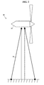
- FIG. 2 illustrates another operating environment.
- the structural cable 16 supports a generally vertical structure 30 .
- the vertical structure 30 is illustrated as a wind turbine 32 , but the vertical structure 30 may be any apparatus (such as a drilling rig, antenna, or tower for utility cables and lines).
- the structural cable 16 stays, or stabilizes, the vertical structure 30 .
- exemplary embodiments greatly reduce the costs of the vertical structure 30 .
- FIGS. 3-5 are more detailed schematics illustrating the structural cable 16 , according to exemplary embodiments.
- FIG. 3 for simplicity, only illustrates a short, longitudinal portion 38 of the structural cable 16 .
- the structural cable 16 can be very long, perhaps hundreds or even thousands of feet in length.
- FIG. 3 thus only illustrates a cross-sectional portion to better illustrate its prefabricated construction.
- the structural cable 16 has a plurality 40 of wires.
- the plurality 40 of wires is illustrated as a bundle 42 having a circular shape 44 .
- the plurality 40 of wires may be bundled in any cross-sectional shape desired (such as hexagonal, triangular, or square).
- Each individual wire 46 in the plurality 40 of wires may be constructed of any metallic and/or non-metallic material.
- An individual wire 46 may be a five (5) or seven (7) millimeter diameter steel wire (or any other diameter or gauge wire suitable for structural cable). Any of the individual wires 46 , however, may be constructed from any metallic material (such as aluminum or copper), carbon fiber material, and/or composite material.
- Each individual wire 46 is illustrated as having a circular cross-sectional shape, but any of the wires 46 may have any other cross-sectional shape (such as hexagonal, triangular, polygonal, or even a variable cross-sectional shape).
- FIG. 4 illustrates a parallel construction.
- the individual wires 46 are substantially parallel to each other. Because the structural cable 16 may be hundreds or thousands of feet in length, FIG. 4 omits a central section for ease of illustration. Regardless, each wire 46 in the plurality 40 of wires is parallel to every other wire 46 .
- the structural cable 16 is a parallel wire cable 50 , where the individual wires 46 are parallel along their entire length L (illustrated as reference numeral 52 ) from the one end 18 to the opposite end 20 .
- Each wire 46 in the plurality 40 of individual wires may also be equal in length 52 to every other wire 46 .
- Each wire 46 in the parallel wire cable 50 in other words, may be parallel to, and equal in length 52 to, every other wire 46 . Because each wire 46 is parallel to every other wire 46 , no winding operation is required.
- the parallel wire cable 50 in other words, need not be spirally or helically wound.
- FIG. 5 illustrates individual tensioning. Exemplary embodiments apply a tension value T (illustrated as reference numeral 60 ) to each wire 46 in the parallel wire cable 50 . In practice there may be many, even hundreds, of the individual wires 46 in the parallel wire cable 50 . FIG. 5 , though, only illustrates a few wires 46 in the parallel wire cable 50 to simplify explanation. Each wire 46 in the plurality 40 of individual wires may have an equal, or nearly equal, tension to every other wire 46 in the parallel wire cable 50 .
- the tension value 60 is applied to one individual wire 62 of the individual wires 46 . An end 64 of the individual wire 62 is mechanically locked, held, or secured in a first fixture 66 . An opposite end 68 of the individual wire 62 is then drawn or pulled to the desired tension value 60 . When the desired tension value 60 is attained, the opposite end 68 of the individual wire 62 is then mechanically locked, held, or secured in a second fixture 70 .
- Pretensioning is repeated. Once the tension value 60 is applied to the individual wire 62 , then a different wire 80 is selected and the same tension value 60 is pulled. Afterwards yet another different wire 46 is sequentially or randomly selected and pulled to the tension value 60 . This pretensioning procedure is repeated until all the individual wires 46 have been individually pulled to approximately the same tension value 60 . Each wire 46 in the plurality 40 of individual wires may thus have the equal tension value 60 to every other wire 46 in the parallel wire cable 50 .
- Tension is applied to each wire 46 , not strands of wires.
- Methods are known that tension strands of plural wires.
- a strand in the art of structural cable, is defined as a group of multiple wires.
- Conventional methods are known that apply tension to a strand of multiple wires.
- Each wire 46 in the plurality 40 of individual wires has the equal tension value 60 as every other wire 46 in the parallel wire cable 50 .
- each wire 46 will provide lighter, cheaper, and stronger cable designs.
- the individually tensioned parallel wire cable 50 weighs significantly less than conventional designs, but the strength of the parallel wire cable 50 is still greater than conventional designs.
- exemplary embodiments may be used to construct the parallel wire cable 50 that is similar in size to conventional designs, but is substantially stronger to support greater loads and/or spans.
- Exemplary embodiments have greater tensile strength, greater compressive strength, greater yield strength, and substantially increased fatigue life when compared to conventional designs, yet exemplary embodiments react the same as any steel member. Exemplary embodiments thus offer greater design alternatives that require less material, production, and transportation costs.
- FIG. 6 is a schematic illustrating prefabrication and preassembly of the parallel wire cable 50 , according to exemplary embodiments.
- exemplary embodiments individually pull each wire 46 in the parallel wire cable 50 .
- Physical testing shows that the resulting parallel wire cable 50 has a similar yield strength to conventional designs of many more wires. That is, exemplary embodiments exhibit similar strength using fewer wires 46 .
- the resulting parallel wire cable 50 thus has a smaller overall diameter, and less weight, than conventional designs using many more wires. Material costs are thus greatly reduced.
- the parallel wire cable 50 may thus be prefabricated and preassembled. As this disclosure earlier explained, the individually tensioned parallel wire cable 50 may be prefabricated offsite in a shop environment, where temperature and other factors are better controlled. Once the plurality 40 of wires has been individually tensioned, exemplary embodiments may seize the parallel wire cable 50 with seizings 90 to maintain the tension value 60 in each wire 46 . The plurality 40 of wires may then be cut to a desired overall length (illustrated as reference numeral 52 in FIG. 4 ). End attachments, known as sockets 92 , may also be added to each end (e.g., illustrated as reference numerals 18 and 20 in FIGS. 1 and 4 ) of the parallel wire cable 50 . Because the parallel wire cable 50 is fabricated and assembled in the shop environment, exemplary embodiments allow preassembly without conventional aerial spinning at a construction site.
- FIG. 7 is a schematic illustrating a memory cast of the preassembled parallel wire cable 50 , according to exemplary embodiments.
- the tension may be removed.
- the preassembled parallel cable 50 may randomly twist and turn in unpredictable directions.
- the preassembled parallel wire cable 50 thus assumes an intricate and confusing configuration creating a random cast 100 of loops.
- Curvature, or cast, in the individual wires (illustrated as reference numeral 46 in FIGS. 3-5 ) causes the random cast 100 of loops.
- each individual wire 46 is manufactured at a foundry, each individual wire 46 has a curvature or cast (usually caused by coiling and reeling).
- the individual wire 46 is then pulled straight to the tension value (as above explained), once released the individual wire 46 has structural memory and bends to return to its original shape.
- the individual memories in the individual wires 46 unpredictably create the random cast 100 of loops.
- the preassembled parallel wire cable 50 assumes the random cast 100 of loops having various convex and concave inflections of differing radii, angle, and/or diameter that may easily tangle.
- FIGS. 8-9 are schematics illustrating a transportation rack 110 , according to exemplary embodiments.
- the preassembled parallel wire cable 50 may exhibit the random cast 100 of loops
- the preassembled parallel wire cable 50 may be advantageously transported without conventional coiling and reeling.
- Conventional manufacturing techniques reel cables onto a large spool, and the spool is then loaded onto a trailer or boat for transport.
- An expensive coiling machine or process is thus conventionally used, which increases handling and tooling costs.
- Exemplary embodiments instead, utilize the memory in the random cast 100 of loops as a handling and transportation feature.
- Exemplary embodiments thus utilize the random cast 100 of loops to avoid and eliminate conventional coiling/reeling techniques.
- the preassembled parallel wire cable 50 is hung from the transportation rack 110 .
- the preassembled parallel cable 50 creates the random cast 100 of loops
- exemplary embodiments advantageously use the random cast 100 of loops for transport.
- any of the random cast 100 of loops may be hung from the rack 110 .
- a human worker or lifting machine need only grasp and hang one or more of the random cast 100 of loops onto the rack 110 .
- the rack 110 may then be moved and loaded onto a trailer, ship, or barge for delivery to the installation site. Because the random cast 100 of loops is hung from the rack 110 , no coiling and reeling operation is needed. Exemplary embodiments thus further reduce the costs of the preassembled parallel cable 50 .
- FIG. 10 is a more detailed schematic illustrating the transportation rack 110 , according to exemplary embodiments.
- the transportation rack 110 may be adjustable to accommodate the unpredictable random cast 100 of loops. Because the preassembled parallel cable 50 may randomly twist and turn in unpredictable directions, workers cannot predict the configuration of the random cast 100 of loops.
- the transportation rack 110 may thus include one or more means for adjusting its hanger configuration to suit the random cast 100 of loops.
- the transportation rack 110 may have one or more arms 120 . Each one of the arms 120 may laterally extend outward from a central beam 122 .
- the central beam 122 may be a hollow-walled tube, such as a steel square or round tube. Because the central beam 122 is hollow, the central beam 122 may include one or more longitudinal slots 124 from which the arms 120 protrude or insert. Each arm 120 may thus longitudinally slide along its corresponding longitudinal slot 124 . Each arm 120 may thus be longitudinally positioned along the central beam 122 to accommodate at least one of the random cast 100 of loops.
- One or more upright supports 126 elevate the central beam 122 to any desired height.
- FIGS. 11-12 are schematics illustrating transport of multiple preassembled parallel wire cables 50 , according to exemplary embodiments.
- the single transportation rack 110 may accommodate multiple preassembled parallel wire cables 50 . That is, multiple preassembled parallel wire cables 50 may be racked or hung from the arms 120 of the transportation rack 110 .
- FIG. 11 illustrates a second preassembled parallel wire cable 130 and a third preassembled parallel wire cable 132 hanging from the arms 120 of the transportation rack 110 .
- the single transportation rack 110 may simultaneously hang many preassembled parallel wire cables 50 . Additional arms 120 may outwardly extend from opposite sides of the central beam 120 .
- the transportation rack 110 may thus be loaded on port and starboard sides with one or more days of production of the preassembled parallel wire cables 50 .
- FIG. 13 is a schematic illustrating sequential racking of the preassembled parallel wire cables 50 , according to exemplary embodiments. As the reader may envision, care may be needed when hanging the multiple preassembled parallel wire cables 50 . As the preassembled parallel cable 50 may randomly twist and turn in unpredictable directions, one or more of the preassembled parallel wire cables 50 may be easily tangled and even knotted. Damage and/or lost time may ensue, thus jeopardizing production efficiency.
- Sequential racking may be desired.
- a worker may first locate and hang a leading one 140 of the sockets 92 .
- the preassembled parallel wire cable 50 may have an orientation identified by the leading socket 140 .
- An opposite, trailing socket 142 readily identifies the other terminal end of the preassembled parallel wire cable 50 .
- the leading socket 140 and the trailing socket 142 may be identified to ensure the preassembled parallel wire cable 50 is correctly oriented for handling and/or for installation.
- the worker then, may first locate and hang the leading socket 140 to a leading or front end 144 of the transportation rack 110 . That is, the leading socket 140 may be hung on or around a leading, first arm 146 of the transportation rack 110 .
- the worker may next locate and hang the trailing socket 142 on or around a last, trailing arm 148 at a trailing or rear end 150 of the transportation rack 110 . No matter how many arms 122 may protrude from the transportation rack 110 , this sequential racking helps ensure the proper orientation is maintained and easily identified. After the leading socket 140 and the trailing socket 142 are sequentially hung, the worker may then proceed to hang any of the random cast 100 of loops. No matter what the configuration of the random cast 100 of loops, this sequential racking ensures the leading and trailing ends of the proper orientation are maintained and identified.
- the leading socket 140 and the trailing socket 142 may be secured to their corresponding arms 146 and 148 .
- Any of the random cast 100 of loops may also be secured to their respective arms 122 .
- Ties, hooks, bands, chain or rope may be quickly wrapped or wound around the preassembled parallel wire cable 50 to ensure the correct orientation is maintained during transport. Indeed, as the rack 110 may be transported long distances across continents and/or oceans, any mechanical fastener, adhesive, or welding may be used to secure the preassembled parallel wire cable 50 to the rack 110 .
- Sequential racking may repeat and continue. Once one preassembled parallel wire cable 50 is hung and secured to the rack 110 , another preassembled parallel wire cable 50 may be hung from the same rack 110 . The leading socket 140 of the another preassembled parallel wire cable 50 is hung to the leading, first arm 146 of the transportation rack 110 . The opposite, trailing socket 142 is then hung to or around the last, trailing arm 148 of the transportation rack 110 . The worker then hangs and secures any of the intervening random cast 100 of loops. Because the preassembled parallel wire cables 50 are sequentially hung from their leading socket 140 , the possibility of entanglement is reduced or nearly eliminated. The worker may thus sequentially hang as many preassembled parallel wire cables 50 as the transportation rack 110 may hold, usually up to some maximum capacity in total number or weight.
- the rack 110 may be loaded on a trailer, ship, or barge for transportation to an installation site.
- the transportation rack 110 may include lifting slots or passageways 160 for insertion of lifting forks.
- a common forklift may thus lift, move, and load the transportation rack 110 onto any carrier's transport. No specialized and/or oversized transport is thus needed to deliver the preassembled parallel wire cables 50 to the installation site.
- FIG. 14 is a schematic illustrating removal of the preassembled parallel wire cables 50 , according to exemplary embodiments.
- the worker merely detaches and pulls the outermost leading socket 140 to sequentially remove the random cast 100 of loops of the corresponding preassembled parallel wire cable 50 .
- the leading socket 140 As the leading socket 140 is pulled, the preassembled parallel wire cable 50 extends and reduces the number of the random cast 100 of loops.
- the preassembled parallel wire cable 50 When the preassembled parallel wire cable 50 is fully extending to nearly its total length, the random cast 100 of loops has been removed by extension. If the preassembled parallel wire cable 50 is too heavy or stiff for human extension, the leading socket 140 may be mechanically pulled (such as by a forklift). Regardless, each preassembled parallel wire cable 50 is easily and quickly removed from the transportation rack 110 .
- FIG. 15 is a schematic illustrating straightening and reeling of the parallel wire cable 50 , according to exemplary embodiments.
- the parallel wire cable 50 may be straightened to reduce, or even remove, the memory cast.
- the parallel wire cable 50 may be fed into a series of rollers 170 .
- Each roller 170 bears down on the parallel wire cable 50 by mechanical or hydraulic force.
- the series of rollers 170 reduces the memory cast in each individual wire 46 , thus producing a generally straight parallel wire cable 50 .
- the generally straight parallel wire cable 50 may then be wound or reeled on a reel 172 for later transport.
- Methods for straightening and reeling steel cables are known, so this disclosure need not repeat known, conventional techniques.
- reeling practicality may be quantified.
- This measure of practicality functionally relates the diameter D PWC of the parallel wire cable 50 to the straightening and reeling operations for the same parallel wire cable 50 .
- the measure of practicality in other words, relates the diameter D PWC of the parallel wire cable 50 to the diameter D Reel of the reel 172 . Again using the two-inch (2 in.) outside, overall diameter, the reader realizes that
- D Reel D PWC ⁇ 240 meaning the diameter D Reel of the reel 172 is about 240 times greater than the two-inch (2 in.) diameter D PWC of the parallel wire cable 50 .
- the practicality function may be non-linear, as smaller diameter cables may be straightened and reeled using existing machinery. Yet the larger the diameter D PWC of the parallel wire cable 50 , then the larger the diameter D Reel of the reel 172 must be, due to non-linear increases in yield strength of exemplary embodiments. Exemplary embodiments, in short, are simply too strong for practical application of straightening and reeling machinery.
- Straightening and reeling is perhaps best performed on the job site. Because exemplary embodiments are so strong, exemplary embodiments are preferably transported with the memory cast, as this disclosure explains. However, if straightening and reeling is desired, these operations are perhaps best suited for the installation site.
- the large rollers of the straightening operation may be set up at the installation site, such as the location of a suspension bridge. Exemplary embodiments may thus be straightened with reduced transportation and handling concerns. Any reeling or coiling operation may also be performed on site. However, given the large diameter reeling operation, roadway property right of ways must be ensured.
- FIG. 16 is a schematic illustrating an additional twisting operation of the parallel wire cable 50 , according to exemplary embodiments. Even if the parallel wire cable 50 is reeled onto the reel 172 , the reeling operation must account for geometric considerations. Exemplary embodiments are much stronger than conventional designs, for any kind of bending, as the above paragraphs explain. As the parallel wire cable 50 is reeled onto the reel 172 , the parallel wire cable 50 is wrapped into a circular coil. The outer ones 174 of the plurality 40 of wires are thus stretched, as the parallel wire cable 50 is reeled onto the reel 172 . Conversely, inner ones 176 of plurality 40 of wires are compressed, as the parallel wire cable 50 is reeled onto the reel 172 .
- the outer wires 174 are subjected to tension and elongate in length, while the inner wires 176 are subjected to compression and shorten in length. Both compression and elongation are greatest at small diameters of the reeling operation. This nearly simultaneous compression and elongation of opposite sides can alter the parallel wire configuration.
- a solution is to introduce a rotational twist 180 of the parallel wire cable 50 with each rotation of the reel 172 . That is, as the parallel wire cable 50 is reeled onto the reel 172 , the parallel wire cable 50 is also longitudinally twisted. Each 360 degree rotation of the reel 172 may require a 360 degree longitudinal twist 180 of the parallel wire cable 50 . The longitudinal twist 180 helps maintain the parallel wire configuration of the plurality 40 of wires.
- the reeling operation is thus greatly complicated. Because the longitudinal twist 180 may be needed with each rotation of the reel 172 , computer control is likely needed. The reeling operation is thus far more expensive and complicated.
- the inventor has thus discovered a further relation between the diameter D PWC of the parallel wire cable 50 and the drum diameter D Reel of the reel 172 .
- the drum diameter D Reel of the reel 172 increases by the square of the diameter D PWC of the parallel wire cable 50 .
- the equipment costs are also similarly related. In simple words, as the parallel wire cable 50 increases in diameter, the reeling operation squares in physical size and cost. Exemplary embodiments, again in short, are simply too strong for practical application of reeling machinery for all but smaller diameters.
- FIG. 17 is a flowchart illustrating a method of transporting the preassembled parallel wire cable 50 , according to exemplary embodiments.
- the parallel wire cable 50 is preassembled creating the random cast 100 of loops (Block 200 ).
- the leading socket 140 is sequentially first hung to the transportation rack 110 (Block 202 ).
- the trailing socket 142 is next hung to the transportation rack 110 (Block 204 ).
- the random cast 100 of loops is then hung to the rack 110 (Block 206 ).
- the rack 110 may be adjusted to suit the random cast 100 of loops (Block 208 ).
- the rack is loaded onto commercial transport, such as trailer, ship, and/or barge (Block 210 ).
- the rack 110 is transported to an installation site (Block 212 ).
- the leading socket 140 is pulled to remove the preassembled parallel wire cable 50 (Block 214 ), which nearly simultaneously reduces the random cast 100 of loops to full extension (Block 216 ).
Landscapes
- Engineering & Computer Science (AREA)
- General Engineering & Computer Science (AREA)
- Mechanical Engineering (AREA)
- Architecture (AREA)
- Civil Engineering (AREA)
- Structural Engineering (AREA)
- Bridges Or Land Bridges (AREA)
- Aviation & Aerospace Engineering (AREA)
- Ocean & Marine Engineering (AREA)
Abstract
A preassembled parallel wire cable creates a random cast of loops. Any of the random cast of loops is hung for transport, thus eliminating costly and time-consuming coiling and reeling operations.
Description
This application relates to U.S. patent application Ser. No. 13/084,693, filed Apr. 12, 2011, and to U.S. patent application Ser. No. 13/946,133, filed Jul. 19, 2013, with both applications incorporated herein by reference in their entireties.
Parallel wire cables have long been desired as structural components. Parallel wire cables, though, twist and coil, making handling and transportation difficult and even unsafe. Conventional manufacturing techniques, then, coil the wire cables, which greatly increases their costs.
The features, aspects, and advantages of the exemplary embodiments are better understood when the following Detailed Description is read with reference to the accompanying drawings, wherein:
The exemplary embodiments will now be described more fully hereinafter with reference to the accompanying drawings. The exemplary embodiments may, however, be embodied in many different forms and should not be construed as limited to the embodiments set forth herein. These embodiments are provided so that this disclosure will be thorough and complete and will fully convey the exemplary embodiments to those of ordinary skill in the art. Moreover, all statements herein reciting embodiments, as well as specific examples thereof, are intended to encompass both structural and functional equivalents thereof. Additionally, it is intended that such equivalents include both currently known equivalents as well as equivalents developed in the future (i.e., any elements developed that perform the same function, regardless of structure).
Thus, for example, it will be appreciated by those of ordinary skill in the art that the diagrams, schematics, illustrations, and the like represent conceptual views or processes illustrating the exemplary embodiments. Those of ordinary skill in the art further understand that the exemplary cables described herein are for illustrative purposes and, thus, are not intended to be limited to any particular manufacturing process and/or manufacturer.
As used herein, the singular forms “a,” “an,” and “the” are intended to include the plural forms as well, unless expressly stated otherwise. It will be further understood that the terms “includes,” “comprises,” “including,” and/or “comprising,” when used in this specification, specify the presence of stated features, integers, steps, operations, elements, and/or components, but do not preclude the presence or addition of one or more other features, integers, steps, operations, elements, components, and/or groups thereof. It will be understood that when an element is referred to as being “connected” or “coupled” to another element, it can be directly connected or coupled to the other element or intervening elements may be present. As used herein, the term “and/or” includes any and all combinations of one or more of the associated listed items.
It will also be understood that, although the terms first, second, etc. may be used herein to describe various elements, these elements should not be limited by these terms. These terms are only used to distinguish one element from another.
Pretensioning is repeated. Once the tension value 60 is applied to the individual wire 62, then a different wire 80 is selected and the same tension value 60 is pulled. Afterwards yet another different wire 46 is sequentially or randomly selected and pulled to the tension value 60. This pretensioning procedure is repeated until all the individual wires 46 have been individually pulled to approximately the same tension value 60. Each wire 46 in the plurality 40 of individual wires may thus have the equal tension value 60 to every other wire 46 in the parallel wire cable 50.
Tension is applied to each wire 46, not strands of wires. Methods are known that tension strands of plural wires. A strand, in the art of structural cable, is defined as a group of multiple wires. Conventional methods are known that apply tension to a strand of multiple wires. Exemplary embodiments, in contradistinction, apply the tension value 60 to each individual wire 46 in the parallel wire cable 50. Each wire 46 in the plurality 40 of individual wires has the equal tension value 60 as every other wire 46 in the parallel wire cable 50.
Individual pretensioning of each wire 46 will provide lighter, cheaper, and stronger cable designs. The individually tensioned parallel wire cable 50 weighs significantly less than conventional designs, but the strength of the parallel wire cable 50 is still greater than conventional designs. Alternatively, exemplary embodiments may be used to construct the parallel wire cable 50 that is similar in size to conventional designs, but is substantially stronger to support greater loads and/or spans. Exemplary embodiments have greater tensile strength, greater compressive strength, greater yield strength, and substantially increased fatigue life when compared to conventional designs, yet exemplary embodiments react the same as any steel member. Exemplary embodiments thus offer greater design alternatives that require less material, production, and transportation costs.
The parallel wire cable 50 may thus be prefabricated and preassembled. As this disclosure earlier explained, the individually tensioned parallel wire cable 50 may be prefabricated offsite in a shop environment, where temperature and other factors are better controlled. Once the plurality 40 of wires has been individually tensioned, exemplary embodiments may seize the parallel wire cable 50 with seizings 90 to maintain the tension value 60 in each wire 46. The plurality 40 of wires may then be cut to a desired overall length (illustrated as reference numeral 52 in FIG. 4 ). End attachments, known as sockets 92, may also be added to each end (e.g., illustrated as reference numerals 18 and 20 in FIGS. 1 and 4 ) of the parallel wire cable 50. Because the parallel wire cable 50 is fabricated and assembled in the shop environment, exemplary embodiments allow preassembly without conventional aerial spinning at a construction site.
As FIG. 8 illustrates, the preassembled parallel wire cable 50 is hung from the transportation rack 110. Even though the preassembled parallel cable 50 creates the random cast 100 of loops, exemplary embodiments advantageously use the random cast 100 of loops for transport. After the parallel wire cable 50 is preassembled, any of the random cast 100 of loops may be hung from the rack 110. A human worker or lifting machine need only grasp and hang one or more of the random cast 100 of loops onto the rack 110. As FIG. 9 illustrates, the rack 110 may then be moved and loaded onto a trailer, ship, or barge for delivery to the installation site. Because the random cast 100 of loops is hung from the rack 110, no coiling and reeling operation is needed. Exemplary embodiments thus further reduce the costs of the preassembled parallel cable 50.
The transportation rack 110 may have one or more arms 120. Each one of the arms 120 may laterally extend outward from a central beam 122. The central beam 122 may be a hollow-walled tube, such as a steel square or round tube. Because the central beam 122 is hollow, the central beam 122 may include one or more longitudinal slots 124 from which the arms 120 protrude or insert. Each arm 120 may thus longitudinally slide along its corresponding longitudinal slot 124. Each arm 120 may thus be longitudinally positioned along the central beam 122 to accommodate at least one of the random cast 100 of loops. One or more upright supports 126 elevate the central beam 122 to any desired height.
Sequential racking may be desired. As FIG. 13 illustrates, once the preassembled parallel wire cable 50 is ready for hanging, a worker may first locate and hang a leading one 140 of the sockets 92. The preassembled parallel wire cable 50 may have an orientation identified by the leading socket 140. An opposite, trailing socket 142 readily identifies the other terminal end of the preassembled parallel wire cable 50. The leading socket 140 and the trailing socket 142 may be identified to ensure the preassembled parallel wire cable 50 is correctly oriented for handling and/or for installation. The worker, then, may first locate and hang the leading socket 140 to a leading or front end 144 of the transportation rack 110. That is, the leading socket 140 may be hung on or around a leading, first arm 146 of the transportation rack 110. The worker may next locate and hang the trailing socket 142 on or around a last, trailing arm 148 at a trailing or rear end 150 of the transportation rack 110. No matter how many arms 122 may protrude from the transportation rack 110, this sequential racking helps ensure the proper orientation is maintained and easily identified. After the leading socket 140 and the trailing socket 142 are sequentially hung, the worker may then proceed to hang any of the random cast 100 of loops. No matter what the configuration of the random cast 100 of loops, this sequential racking ensures the leading and trailing ends of the proper orientation are maintained and identified.
Securements may be used. Once the worker hangs the preassembled parallel wire cable 50 to the rack 110, the leading socket 140 and the trailing socket 142 may be secured to their corresponding arms 146 and 148. Any of the random cast 100 of loops may also be secured to their respective arms 122. Ties, hooks, bands, chain or rope may be quickly wrapped or wound around the preassembled parallel wire cable 50 to ensure the correct orientation is maintained during transport. Indeed, as the rack 110 may be transported long distances across continents and/or oceans, any mechanical fastener, adhesive, or welding may be used to secure the preassembled parallel wire cable 50 to the rack 110.
Sequential racking may repeat and continue. Once one preassembled parallel wire cable 50 is hung and secured to the rack 110, another preassembled parallel wire cable 50 may be hung from the same rack 110. The leading socket 140 of the another preassembled parallel wire cable 50 is hung to the leading, first arm 146 of the transportation rack 110. The opposite, trailing socket 142 is then hung to or around the last, trailing arm 148 of the transportation rack 110. The worker then hangs and secures any of the intervening random cast 100 of loops. Because the preassembled parallel wire cables 50 are sequentially hung from their leading socket 140, the possibility of entanglement is reduced or nearly eliminated. The worker may thus sequentially hang as many preassembled parallel wire cables 50 as the transportation rack 110 may hold, usually up to some maximum capacity in total number or weight.
Transportation then occurs. Once the one or more preassembled parallel wire cables 50 are hung to the transportation rack 110, the rack 110 may be loaded on a trailer, ship, or barge for transportation to an installation site. As FIG. 13 illustrates, the transportation rack 110 may include lifting slots or passageways 160 for insertion of lifting forks. A common forklift may thus lift, move, and load the transportation rack 110 onto any carrier's transport. No specialized and/or oversized transport is thus needed to deliver the preassembled parallel wire cables 50 to the installation site.
Practical considerations arise. Because exemplary embodiments are so much stronger than conventional cables, straightening and reeling operations can become impractical for larger diameter wires. For example, the parallel wire cable 50, having a two-inch (2 in.) diameter of the individually tensioned wires, would require the reel 172 to have a diameter of over forty (40) feet. Such a large reel 172 is impractical to load and transport. Moreover, straightening and reeling a two-inch (2 in.) diameter cable 50 would require massive mechanical capabilities, which also greatly increases machinery costs and shop footprint.
Indeed, reeling practicality may be quantified. The inventor has discovered that any reeling operation may be related to the overall diameter of the parallel wire cable 50, according to the relationship
Practicality=f(D PWC),
where DPWC is the diameter of theparallel wire cable 50. This measure of practicality functionally relates the diameter DPWC of the parallel wire cable 50 to the straightening and reeling operations for the same parallel wire cable 50. The measure of practicality, in other words, relates the diameter DPWC of the parallel wire cable 50 to the diameter DReel of the reel 172. Again using the two-inch (2 in.) outside, overall diameter, the reader realizes that
Practicality=f(D PWC),
where DPWC is the diameter of the
meaning the diameter DReel of the
Straightening and reeling is perhaps best performed on the job site. Because exemplary embodiments are so strong, exemplary embodiments are preferably transported with the memory cast, as this disclosure explains. However, if straightening and reeling is desired, these operations are perhaps best suited for the installation site. The large rollers of the straightening operation may be set up at the installation site, such as the location of a suspension bridge. Exemplary embodiments may thus be straightened with reduced transportation and handling concerns. Any reeling or coiling operation may also be performed on site. However, given the large diameter reeling operation, roadway property right of ways must be ensured.
The reeling operation is thus greatly complicated. Because the longitudinal twist 180 may be needed with each rotation of the reel 172, computer control is likely needed. The reeling operation is thus far more expensive and complicated. The inventor has thus discovered a further relation between the diameter DPWC of the parallel wire cable 50 and the drum diameter DReel of the reel 172. The drum diameter DReel of the reel 172 increases by the square of the diameter DPWC of the parallel wire cable 50. The equipment costs are also similarly related. In simple words, as the parallel wire cable 50 increases in diameter, the reeling operation squares in physical size and cost. Exemplary embodiments, again in short, are simply too strong for practical application of reeling machinery for all but smaller diameters.
While the exemplary embodiments have been described with respect to various features, aspects, and embodiments, those skilled and unskilled in the art will recognize the exemplary embodiments are not so limited. Other variations, modifications, and alternative embodiments may be made without departing from the spirit and scope of the exemplary embodiments.
Claims (11)
1. A method, comprising:
preassembling a plurality of metallic wires arranged in a bundle as a parallel wire structural cable, the parallel wire structural cable having a random cast of loops; and
hanging the random cast of loops unreeled on a rack for transport.
2. The method of claim 1 , further comprising individually pulling each metallic wire in the plurality of metallic wires.
3. The method of claim 1 , further comprising individually pulling each metallic wire in the plurality of metallic wires to a tension value.
4. The method of claim 1 , further comprising adjusting the rack to a number of the random cast of loops after the preassembling of the plurality of metallic wires.
5. The method of claim 1 , further comprising loading the rack for the transport.
6. The method of claim 1 , further comprising extending the parallel wire structural cable during a removal from the rack to reduce the random cast of loops.
7. The method of claim 1 , further comprising sequentially hanging the random cast of loops starting from a leading socket.
8. A method, comprising:
receiving a preassembled parallel wire structural cable having a random cast of loops hanging unreeled from a rack, the parallel wire structural cable preassembled from a plurality of metallic wires arranged in a bundle, the plurality of metallic wires having individual memory causing the random cast of loops in the preassembled parallel wire structural cable; and
transporting the random cast of loops in the preassembled parallel wire structural cable hanging unreeled to the rack.
9. The method of claim 8 , further comprising loading the rack onto a trailer.
10. The method of claim 8 , further comprising loading the rack onto a ship.
11. The method of claim 8 , further comprising loading the rack onto a barge.
Priority Applications (5)
| Application Number | Priority Date | Filing Date | Title |
|---|---|---|---|
| US14/283,292 US9743764B2 (en) | 2011-04-12 | 2014-05-21 | Transportation of parallel wire cable |
| US15/656,151 US10149536B2 (en) | 2011-04-12 | 2017-07-21 | Transportation of Parallel wire cable |
| US16/185,049 US10376051B2 (en) | 2011-04-12 | 2018-11-09 | Transportation of parallel wire cable |
| US16/454,182 US10962145B2 (en) | 2011-04-12 | 2019-06-27 | Transportation of parallel wire cable |
| US17/142,310 US11287065B2 (en) | 2011-04-12 | 2021-01-06 | Manufacturing of parallel wire cable |
Applications Claiming Priority (3)
| Application Number | Priority Date | Filing Date | Title |
|---|---|---|---|
| US13/084,693 US20120260590A1 (en) | 2011-04-12 | 2011-04-12 | Parallel Wire Cable |
| US13/946,133 US20130309521A1 (en) | 2011-04-12 | 2013-07-19 | Parallel Wire Cable |
| US14/283,292 US9743764B2 (en) | 2011-04-12 | 2014-05-21 | Transportation of parallel wire cable |
Related Child Applications (1)
| Application Number | Title | Priority Date | Filing Date |
|---|---|---|---|
| US15/656,151 Continuation US10149536B2 (en) | 2011-04-12 | 2017-07-21 | Transportation of Parallel wire cable |
Publications (2)
| Publication Number | Publication Date |
|---|---|
| US20150335154A1 US20150335154A1 (en) | 2015-11-26 |
| US9743764B2 true US9743764B2 (en) | 2017-08-29 |
Family
ID=47005338
Family Applications (11)
| Application Number | Title | Priority Date | Filing Date |
|---|---|---|---|
| US13/084,693 Abandoned US20120260590A1 (en) | 2011-04-12 | 2011-04-12 | Parallel Wire Cable |
| US13/946,133 Abandoned US20130309521A1 (en) | 2011-04-12 | 2013-07-19 | Parallel Wire Cable |
| US14/283,292 Active 2035-06-24 US9743764B2 (en) | 2011-04-12 | 2014-05-21 | Transportation of parallel wire cable |
| US15/656,151 Active US10149536B2 (en) | 2011-04-12 | 2017-07-21 | Transportation of Parallel wire cable |
| US15/911,074 Active US10278493B2 (en) | 2011-04-12 | 2018-03-03 | Parallel wire cable |
| US16/185,049 Active US10376051B2 (en) | 2011-04-12 | 2018-11-09 | Transportation of parallel wire cable |
| US16/361,455 Active US10758041B2 (en) | 2011-04-12 | 2019-03-22 | Parallel wire cable |
| US16/454,182 Active US10962145B2 (en) | 2011-04-12 | 2019-06-27 | Transportation of parallel wire cable |
| US16/857,220 Active US10955069B2 (en) | 2011-04-12 | 2020-04-24 | Parallel wire cable |
| US17/142,307 Active US11187352B2 (en) | 2011-04-12 | 2021-01-06 | Parallel wire cable |
| US17/142,310 Active US11287065B2 (en) | 2011-04-12 | 2021-01-06 | Manufacturing of parallel wire cable |
Family Applications Before (2)
| Application Number | Title | Priority Date | Filing Date |
|---|---|---|---|
| US13/084,693 Abandoned US20120260590A1 (en) | 2011-04-12 | 2011-04-12 | Parallel Wire Cable |
| US13/946,133 Abandoned US20130309521A1 (en) | 2011-04-12 | 2013-07-19 | Parallel Wire Cable |
Family Applications After (8)
| Application Number | Title | Priority Date | Filing Date |
|---|---|---|---|
| US15/656,151 Active US10149536B2 (en) | 2011-04-12 | 2017-07-21 | Transportation of Parallel wire cable |
| US15/911,074 Active US10278493B2 (en) | 2011-04-12 | 2018-03-03 | Parallel wire cable |
| US16/185,049 Active US10376051B2 (en) | 2011-04-12 | 2018-11-09 | Transportation of parallel wire cable |
| US16/361,455 Active US10758041B2 (en) | 2011-04-12 | 2019-03-22 | Parallel wire cable |
| US16/454,182 Active US10962145B2 (en) | 2011-04-12 | 2019-06-27 | Transportation of parallel wire cable |
| US16/857,220 Active US10955069B2 (en) | 2011-04-12 | 2020-04-24 | Parallel wire cable |
| US17/142,307 Active US11187352B2 (en) | 2011-04-12 | 2021-01-06 | Parallel wire cable |
| US17/142,310 Active US11287065B2 (en) | 2011-04-12 | 2021-01-06 | Manufacturing of parallel wire cable |
Country Status (4)
| Country | Link |
|---|---|
| US (11) | US20120260590A1 (en) |
| EP (1) | EP2580407B1 (en) |
| CA (1) | CA2835083C (en) |
| WO (1) | WO2012142004A2 (en) |
Cited By (2)
| Publication number | Priority date | Publication date | Assignee | Title |
|---|---|---|---|---|
| US10149536B2 (en) * | 2011-04-12 | 2018-12-11 | Ultimate Strength Cable, LLC | Transportation of Parallel wire cable |
| US10508644B2 (en) | 2011-04-12 | 2019-12-17 | Ultimate Strength Cable, LLC | Stay cable for structures |
Families Citing this family (5)
| Publication number | Priority date | Publication date | Assignee | Title |
|---|---|---|---|---|
| AU2010336022B2 (en) * | 2009-12-23 | 2014-08-14 | Geotech Pty Ltd | An anchorage system |
| CN105421244B (en) * | 2015-12-10 | 2017-07-28 | 江苏法尔胜缆索有限公司 | A kind of preparation method of main rope of suspension bridge Prefabricated parallel preshaping of wire strand |
| DE102018200685A1 (en) * | 2018-01-17 | 2019-07-18 | Leoni Kabei Gmbh | Wire, in particular for a strand |
| US10676952B2 (en) | 2018-01-26 | 2020-06-09 | General Electric Company | System and method for stabilizing a wind turbine |
| CN110344328A (en) * | 2019-07-11 | 2019-10-18 | 广东迈诺工业技术有限公司 | A kind of production method of hot extruded polyethylene Zn-Al Alloy Coated Steel Wire drag-line |
Citations (62)
| Publication number | Priority date | Publication date | Assignee | Title |
|---|---|---|---|---|
| US364077A (en) | 1887-05-31 | Windmill-tower | ||
| US1459623A (en) | 1923-06-19 | Machine for making bale ties | ||
| US1537698A (en) | 1924-10-15 | 1925-05-12 | Holton D Robinson | Laying of and seizing for suspension-bridge cables |
| US2095721A (en) | 1932-05-24 | 1937-10-12 | Roeblings John A Sons Co | Wire cable |
| US2501202A (en) * | 1948-01-23 | 1950-03-21 | Bartleman Richard | Cable testing lead rack |
| US2803363A (en) * | 1955-03-07 | 1957-08-20 | Samuel V Hutchinson | Roll handling attachment for industrial lift trucks |
| US2808845A (en) * | 1954-12-27 | 1957-10-08 | Wood Dora De Jarnatt | Swimming pool cover |
| US2878498A (en) * | 1953-06-27 | 1959-03-24 | Gollnow Werke A G | Bridge construction |
| US2945457A (en) | 1956-10-01 | 1960-07-19 | Gen Electric | Rail vehicle suspension cable |
| US3083817A (en) | 1953-11-18 | 1963-04-02 | British Ropes Ltd | Wire ropes |
| US3086232A (en) * | 1960-10-12 | 1963-04-23 | Colorado Fuel & Iron Corp | Method of and apparatus for spinning cables for suspension bridges |
| US3153696A (en) | 1956-03-12 | 1964-10-20 | Schlumberger Well Surv Corp | Methods for processing cables |
| US3500625A (en) | 1967-05-17 | 1970-03-17 | Isao Gokyu | Parallel cables |
| US3526570A (en) | 1966-08-25 | 1970-09-01 | Bethlehem Steel Corp | Parallel wire strand |
| US3531811A (en) | 1968-10-15 | 1970-10-06 | Bethlehem Steel Corp | Method for erecting parallel-wire bridge strand |
| US3542087A (en) | 1968-05-14 | 1970-11-24 | Western Electric Co | Methods of and apparatus for straightening leads |
| US3556168A (en) | 1967-11-13 | 1971-01-19 | Bethlehem Steel Corp | Apparatus for applying fittings to strand ends |
| US3659633A (en) | 1966-08-25 | 1972-05-02 | Bethlehem Steel Corp | Method of making parallel wire strand |
| US3756008A (en) | 1972-08-23 | 1973-09-04 | Helistrand Inc | Self-coiling wire cable and method of forming same |
| US3919762A (en) | 1972-08-05 | 1975-11-18 | Wolfgang Borelly | Process for the manufacture of parallel wire strands for bridges and the like by winding and unwinding |
| US4203267A (en) | 1978-07-31 | 1980-05-20 | Bethlehem Steel Corporation | Multiple strand tower guy assembly |
| US4258518A (en) | 1977-12-30 | 1981-03-31 | Freyssinet International | Possibly removable device for guiding the deflection of stretched cables |
| US4488649A (en) * | 1981-10-27 | 1984-12-18 | Larry D. Watts | Rack for plural cylindrical objects |
| US4533297A (en) | 1982-09-15 | 1985-08-06 | Bassett David A | Rotor system for horizontal axis wind turbines |
| US4594827A (en) | 1981-09-30 | 1986-06-17 | Dyckerhoff & Widmann Aktiengesellschaft | Tension member, particularly for use as a diagonal cable in a stayed girder bridge |
| US4617789A (en) | 1985-04-01 | 1986-10-21 | The United States Of America As Represented By The United States Department Of Energy | Apparatus and method for fabricating multi-strand superconducting cable |
| US4673309A (en) | 1984-09-25 | 1987-06-16 | Schlaich Joerg | Method and apparatus for anchoring cables of high-tensile steel wire |
| US4841714A (en) * | 1986-07-21 | 1989-06-27 | Ferag Ag | Method and apparatus for the further processing of a packaging line |
| US5056284A (en) | 1988-07-19 | 1991-10-15 | Dyckerhoff & Widmann Ag | Bundled tensioning member for prestressing a tall structural member and method of installing same |
| US5083469A (en) | 1989-10-05 | 1992-01-28 | Freyssinet International (Stup) | Methods and devices for placing multiple strand cables under tension |
| US5688098A (en) * | 1996-01-04 | 1997-11-18 | Theno; Mark H. | Roll transfer system |
| US6109460A (en) * | 1996-11-26 | 2000-08-29 | Instrumentarium Corporation | Suspension rack |
| US6315249B1 (en) * | 1999-12-29 | 2001-11-13 | Dell Usa, L.P. | System for managing cables for a rack-mounted computer system |
| US20020095878A1 (en) | 2000-12-05 | 2002-07-25 | Henderson Allan P. | Tilt-up and telescopic support tower for large structures |
| US6523776B1 (en) * | 1999-04-23 | 2003-02-25 | Doyle W. Elder | Wire dispensing device |
| US6614125B2 (en) | 2000-05-02 | 2003-09-02 | Valmont Industries, Inc. | Method and means for mounting a wind turbine on a tower |
| US6658684B2 (en) | 1999-09-15 | 2003-12-09 | Freyssinet International (Stup) | Cable with parallel wires for building work structure, anchoring for said cable and anchoring method |
| US6944550B2 (en) | 2000-09-08 | 2005-09-13 | Michel Marchetti | Method for tensioning multiple-strand cables |
| US6979175B2 (en) | 2002-10-17 | 2005-12-27 | Devon Glen Drake | Downstream wind turbine |
| US7003835B2 (en) | 2002-04-02 | 2006-02-28 | Figg Bridge Engineers, Inc. | Cable-stay cradle system |
| US7010824B2 (en) | 2003-06-02 | 2006-03-14 | Freyssinet International (Stup) | Method for anchoring parallel wire cables and suspension system for a construction work |
| US7124460B2 (en) | 2003-03-24 | 2006-10-24 | Freyssinet International (Stup) | Construction cable |
| US7188814B2 (en) * | 2004-06-15 | 2007-03-13 | Davis Jerry A | Cord holder with integral locking mechanism |
| US20080116152A1 (en) * | 2006-11-17 | 2008-05-22 | C.E. Communication Services, Inc. | Cable management bracket |
| US20080210330A1 (en) | 2004-10-22 | 2008-09-04 | Beast Cabling Systems, Inc. | Cabling Continuous Deployment System and Tool |
| US7431610B2 (en) * | 2005-01-21 | 2008-10-07 | Leviton Manufacturing Co., Inc. | Cable slack manager system and method |
| US7508088B2 (en) | 2005-06-30 | 2009-03-24 | General Electric Company | System and method for installing a wind turbine at an offshore location |
| US20090126313A1 (en) | 2007-11-15 | 2009-05-21 | Tony Jolly | System and method for erecting a tower |
| US20090167023A1 (en) | 2007-12-27 | 2009-07-02 | Jacob Johannes Nies | Forward leaning tower top section |
| US20090224498A1 (en) * | 2008-03-07 | 2009-09-10 | Diedericks Johannes P L | Wire and Cable Assembly Device and Associated Methods |
| US20090307998A1 (en) | 2008-06-13 | 2009-12-17 | Tindall Corporation | Base support for wind-driven power generators |
| US7683498B2 (en) | 2006-07-04 | 2010-03-23 | Daubner & Stommel GBR Bau-Werk-Planug | Method for operation of a wind energy installation |
| US20100090053A1 (en) * | 2008-10-09 | 2010-04-15 | Rodney Stiltner | Hitch Wire Stand |
| US20100322766A1 (en) | 2009-06-17 | 2010-12-23 | Wouter Haans | Wind turbine and method for optimizing energy production therein |
| US20100319983A1 (en) | 2007-02-28 | 2010-12-23 | De Abreu Paulo Emmanuel | Structure for supporting electric power transmission lines |
| US20110206510A1 (en) | 2010-12-20 | 2011-08-25 | Reinhard Langen | Modular rotor blade and method for mounting a wind turbine |
| US20110278852A1 (en) | 2008-12-16 | 2011-11-17 | Vestas Wind Systems A/S | Wind turbine nacelle |
| US20120139253A1 (en) | 2011-07-13 | 2012-06-07 | Lambert Walter L | Stay Cable for Structures |
| US20120260590A1 (en) | 2011-04-12 | 2012-10-18 | Lambert Walter L | Parallel Wire Cable |
| US20130305624A1 (en) * | 2011-11-23 | 2013-11-21 | Parallax Group International, Llc | Wall Mounting Devices |
| US8759678B2 (en) * | 2011-12-25 | 2014-06-24 | Alexander Filatov | Cable storage device and associated methods |
| US8967943B2 (en) * | 2010-01-19 | 2015-03-03 | Green Wood Logistics Ab | Load carrier for transport of wood |
Family Cites Families (82)
| Publication number | Priority date | Publication date | Assignee | Title |
|---|---|---|---|---|
| DE459035C (en) | 1928-04-25 | Aero Dynamo Akt Ges | Tubular mast for wind turbines | |
| US448786A (en) | 1891-03-24 | Henry ogden | ||
| US3104778A (en) * | 1963-09-24 | Wire holder and dispenser assembly | ||
| US1254737A (en) | 1917-06-08 | 1918-01-29 | Walter Duke Smithey | Means for generating and storing power. |
| US2141138A (en) * | 1936-10-26 | 1938-12-20 | American Steel & Wire Co | Bridge cable strand |
| US2098721A (en) | 1936-11-30 | 1937-11-09 | Demarest Daniel Dougias | Resilient fastener |
| US3379000A (en) * | 1965-09-15 | 1968-04-23 | Roehr Prod Co Inc | Metal filaments suitable for textiles |
| DE1596151A1 (en) | 1965-12-30 | 1971-04-29 | Lucas Industries Ltd | Process for the production of oxygen electrodes |
| US3443607A (en) * | 1967-01-04 | 1969-05-13 | Malmedie & Co Maschf | Wire straightener |
| US3586226A (en) * | 1968-10-03 | 1971-06-22 | Bethlehem Steel Corp | Pulling system for parallel-wire strand |
| DE1921897A1 (en) * | 1969-04-29 | 1970-11-12 | Teves Gmbh Alfred | Shock absorber device, especially for railroad cars |
| DE1938931C3 (en) * | 1969-07-31 | 1978-03-16 | Hein Lehmann Ag, 4000 Duesseldorf | Method for producing a parallel wire bundle |
| US3715877A (en) | 1969-10-27 | 1973-02-13 | Oki Electric Cable | Communication cable |
| US3885777A (en) * | 1969-10-29 | 1975-05-27 | Bourcier Carbon Christian | Level corrector for shock absorbers |
| US3726075A (en) | 1970-04-07 | 1973-04-10 | Oki Electric Cable | Variable pitch-type cable core twister |
| JPS5039069B1 (en) * | 1971-03-02 | 1975-12-13 | ||
| GB1400708A (en) * | 1971-09-02 | 1975-07-23 | Bekaert Sa Nv | Heat treatment of steel wire reinforcements |
| US3777428A (en) | 1972-04-19 | 1973-12-11 | E Caufield | Observation signal device and components thereof |
| US4192057A (en) * | 1972-08-05 | 1980-03-11 | Borrelly Wolfgang | Process and apparatus for the production of corrosion protection for cables made of parallel wire strands |
| DE2806081C2 (en) | 1978-02-14 | 1982-04-22 | Voith Getriebe Kg, 7920 Heidenheim | Mast, especially for wind turbines |
| DE2812100A1 (en) * | 1978-03-20 | 1979-10-04 | Barmag Barmer Maschf | PROCESS FOR PARALLEL LEADING A COMPOSITE STRING AND DEVICE FOR CARRYING OUT THE PROCESS |
| DE2823525C2 (en) | 1978-05-30 | 1985-05-09 | M.A.N. Maschinenfabrik Augsburg-Nuernberg Ag, 8000 Muenchen | Wind turbine and method for its construction |
| US4409050A (en) | 1979-05-10 | 1983-10-11 | Carter Wind Power | Method of making blade supports |
| DE3227700A1 (en) | 1982-07-24 | 1984-01-26 | BÖWE Maschinenfabrik GmbH, 8900 Augsburg | WIND ENERGY CONVERTER |
| US4545728A (en) | 1983-08-30 | 1985-10-08 | Cheney Jr Marvin C | Wind turbine generator with improved operating subassemblies |
| DE3437108A1 (en) * | 1984-10-10 | 1986-04-10 | Dyckerhoff & Widmann AG, 8000 München | DEVICE FOR USE IN THE ASSEMBLY OF A TENSION MEMBER OF STEEL WIRE, STRAND, OR THE LIKE |
| DE3769580D1 (en) * | 1986-10-10 | 1991-05-29 | Bekaert Sa Nv | REINFORCEMENT STRIP FOR RUBBER TIRES. |
| US4792700A (en) | 1987-04-14 | 1988-12-20 | Ammons Joe L | Wind driven electrical generating system |
| EP0393013B2 (en) * | 1989-04-12 | 1997-06-25 | Vorspann-Technik Gesellschaft m.b.H. | Tensioning-bundle comprising tensioning members |
| US4979871A (en) | 1989-11-17 | 1990-12-25 | Reiner Harold E | Wind turbine |
| DE3939862C2 (en) | 1989-12-01 | 1996-07-11 | Heidelberg Goetz | Wind turbine |
| FR2655765B1 (en) * | 1989-12-13 | 1994-07-22 | Lens Cableries | CABLE FOR AERIAL POWER LINE FOR TRANSPORTING ENERGY, AND METHODS AND DEVICES FOR MANUFACTURING SUCH A CABLE. |
| JPH03222872A (en) | 1990-01-29 | 1991-10-01 | Mitsubishi Heavy Ind Ltd | Yaw control method for windmill |
| US5400584A (en) * | 1993-09-29 | 1995-03-28 | Tokyo Roe Mfg. Co., Ltd. | Cable manufacturing method |
| US5543196A (en) * | 1994-07-26 | 1996-08-06 | Robinson; Michael D. | Selvedge reinforcement |
| US5956935A (en) * | 1995-03-17 | 1999-09-28 | Tokyo Rope Manufacturing Co., Ltd. | High tensile steel filament member for rubber product reinforcement |
| JP2772627B2 (en) * | 1995-05-16 | 1998-07-02 | 東京製綱株式会社 | Ultra-high strength steel wire and steel cord for rubber reinforcement |
| DE19536701C2 (en) * | 1995-09-30 | 1999-07-15 | Dyckerhoff & Widmann Ag | Method for tensioning a tension member from a plurality of individual elements |
| EP1013830A1 (en) * | 1998-12-24 | 2000-06-28 | Freyssinet International Stup | Device and process for fastening a building element and a cable structure and suspension bridge having such devices |
| FR2791031B1 (en) | 1999-03-19 | 2001-05-18 | Adder Sa | MOBILE CLASS SEPARATOR IN A COCKPIT LIKE AN AIRCRAFT |
| US6968779B2 (en) * | 2000-03-15 | 2005-11-29 | Enterprises International, Inc. | Apparatus and methods for wire-tying bundles of objects |
| US6682302B2 (en) | 2001-03-20 | 2004-01-27 | James D. Noble | Turbine apparatus and method |
| GB2391872B (en) * | 2001-04-27 | 2005-03-16 | Conoco Inc | Composite tether and methods for manufacturing transporting and installing same |
| SE525387C2 (en) | 2002-01-10 | 2005-02-08 | Swedish Vertical Wind Ab | Vertical axle wind turbine and its use |
| US6800956B2 (en) | 2002-01-30 | 2004-10-05 | Lexington Bartlett | Wind power system |
| DE10224439C5 (en) | 2002-06-01 | 2009-12-31 | Aloys Wobben | Method for assembly / disassembly of components of a wind turbine |
| JP3941624B2 (en) | 2002-07-30 | 2007-07-04 | コニカミノルタビジネステクノロジーズ株式会社 | File storage device |
| EP1411170A1 (en) * | 2002-10-15 | 2004-04-21 | Fatzer Ag | Tendon, especially for the suspension of construction elements and manufacturing method thereof |
| FR2849070B1 (en) * | 2002-12-18 | 2005-03-04 | Freyssinet Int Stup | METHOD FOR MOUNTING A HAUBAN |
| US20040247438A1 (en) | 2003-02-20 | 2004-12-09 | Mccoin Dan Keith | Wind energy conversion system |
| DE10308125A1 (en) | 2003-02-26 | 2004-09-09 | Ranit-Befestigungssysteme Gmbh | clamp |
| DE10309825A1 (en) | 2003-03-05 | 2004-09-16 | Bosch Rexroth Ag | Wind generator installation with mast provided with stay wires has vibration dampers fitted in stay wires |
| US7076985B2 (en) * | 2004-03-03 | 2006-07-18 | Howard Thomas Rex | Wire winding machine |
| US7105940B2 (en) | 2004-03-31 | 2006-09-12 | General Electric Company | Mobile renewable energy generator |
| US7650742B2 (en) | 2004-10-19 | 2010-01-26 | Tokyo Rope Manufacturing Co., Ltd. | Cable made of high strength fiber composite material |
| US8069634B2 (en) | 2006-10-02 | 2011-12-06 | General Electric Company | Lifting system and apparatus for constructing and enclosing wind turbine towers |
| NO20071147A (en) | 2007-02-28 | 2008-08-11 | Weightless Values As | Downwind wind turbines and a procedure for operating a downwind wind turbine |
| DE102007017697A1 (en) | 2007-04-14 | 2008-10-23 | Dywidag-Systems International Gmbh | Tension member for structures and method for its production |
| US7677506B1 (en) * | 2008-05-02 | 2010-03-16 | Hammer Douglas A | Truck air hose holder |
| CN102224284B (en) * | 2008-11-25 | 2013-06-19 | 贝卡尔特公司 | Metal fiber yarn with enhanced strength and processability |
| US20100226774A1 (en) | 2009-02-25 | 2010-09-09 | Kenneth James Deering | Wind turbine control system and apparatus |
| US20110016804A1 (en) | 2009-07-22 | 2011-01-27 | Lonnie Howard | Ultra-light, re-usable, extended-height meteorological tower apparatus and method |
| FR2955609B1 (en) * | 2010-01-26 | 2012-04-27 | Snecma | AUBE COMPOSITE WITH INTERNAL CHANNELS |
| US20120045345A1 (en) | 2010-08-20 | 2012-02-23 | Horton Wison Deepwater, Inc. | Offshore wind turbine and methods of installing same |
| BR112013008611A2 (en) * | 2010-10-11 | 2016-06-14 | Ideal Ind | cable connection devices and methods for using the same |
| US9334091B2 (en) * | 2010-10-11 | 2016-05-10 | Ideal Industries, Inc. | Cable lacing tie devices and methods of using the same |
| ITRM20110516A1 (en) | 2011-09-30 | 2013-03-31 | Enel Green Power Spa | HORIZONTAL AXIS WIND GENERATOR WITH SECONDARY WIND ROTOR |
| US20130164134A1 (en) | 2011-12-23 | 2013-06-27 | Leonid Goldstein | Limited Yaw Wind Turbine |
| US8758120B2 (en) | 2012-02-17 | 2014-06-24 | Wms Gaming, Inc. | Community game having online and land-based game play |
| DE102012220502A1 (en) | 2012-11-09 | 2014-06-12 | Wobben Properties Gmbh | Wind turbine |
| CN103090825A (en) | 2012-12-10 | 2013-05-08 | 陕西西北铁道电子有限公司 | Compatible railroad bridge condition monitoring system based on Beidou satellite |
| US8881471B1 (en) | 2012-12-27 | 2014-11-11 | Daniel Theobald | Guy wire control apparatus and method |
| US9353730B2 (en) | 2013-06-10 | 2016-05-31 | Uprise Energy, LLC | Wind energy devices, systems, and methods |
| US20150001283A1 (en) | 2013-06-28 | 2015-01-01 | Earthling, Llc | Mailbox having solar power |
| DE102013012429B3 (en) * | 2013-07-29 | 2014-09-11 | Dywidag-Systems International Gmbh | Protection system for tension members of a structure for catching ice accumulations releasing from a tension member |
| PT2846041T (en) | 2013-09-06 | 2018-03-20 | youWINenergy GmbH | Retrofitted wind turbine installation |
| PT2846040T (en) | 2013-09-06 | 2018-06-06 | youWINenergy GmbH | Tower assembly for a wind turbine installation |
| NO2776494T3 (en) | 2014-07-01 | 2018-09-29 | ||
| DE102015000818B3 (en) | 2014-11-27 | 2015-12-17 | Horst Bendix | Wind turbine tower |
| GB2533159A (en) * | 2014-12-12 | 2016-06-15 | Exergyn Ltd | Wire element arrangement in an energy recovery device |
| US9759194B2 (en) | 2015-10-23 | 2017-09-12 | John Tucciarone | Portable power generator |
| CN108979949B (en) | 2018-08-02 | 2020-09-18 | 李秋辐 | Windward self-adjusting high-altitude wind collecting and generating device |
-
2011
- 2011-04-12 US US13/084,693 patent/US20120260590A1/en not_active Abandoned
-
2012
- 2012-04-10 EP EP12771353.5A patent/EP2580407B1/en active Active
- 2012-04-10 WO PCT/US2012/032826 patent/WO2012142004A2/en active Application Filing
- 2012-04-10 CA CA2835083A patent/CA2835083C/en active Active
-
2013
- 2013-07-19 US US13/946,133 patent/US20130309521A1/en not_active Abandoned
-
2014
- 2014-05-21 US US14/283,292 patent/US9743764B2/en active Active
-
2017
- 2017-07-21 US US15/656,151 patent/US10149536B2/en active Active
-
2018
- 2018-03-03 US US15/911,074 patent/US10278493B2/en active Active
- 2018-11-09 US US16/185,049 patent/US10376051B2/en active Active
-
2019
- 2019-03-22 US US16/361,455 patent/US10758041B2/en active Active
- 2019-06-27 US US16/454,182 patent/US10962145B2/en active Active
-
2020
- 2020-04-24 US US16/857,220 patent/US10955069B2/en active Active
-
2021
- 2021-01-06 US US17/142,307 patent/US11187352B2/en active Active
- 2021-01-06 US US17/142,310 patent/US11287065B2/en active Active
Patent Citations (63)
| Publication number | Priority date | Publication date | Assignee | Title |
|---|---|---|---|---|
| US1459623A (en) | 1923-06-19 | Machine for making bale ties | ||
| US364077A (en) | 1887-05-31 | Windmill-tower | ||
| US1537698A (en) | 1924-10-15 | 1925-05-12 | Holton D Robinson | Laying of and seizing for suspension-bridge cables |
| US2095721A (en) | 1932-05-24 | 1937-10-12 | Roeblings John A Sons Co | Wire cable |
| US2501202A (en) * | 1948-01-23 | 1950-03-21 | Bartleman Richard | Cable testing lead rack |
| US2878498A (en) * | 1953-06-27 | 1959-03-24 | Gollnow Werke A G | Bridge construction |
| US3083817A (en) | 1953-11-18 | 1963-04-02 | British Ropes Ltd | Wire ropes |
| US2808845A (en) * | 1954-12-27 | 1957-10-08 | Wood Dora De Jarnatt | Swimming pool cover |
| US2803363A (en) * | 1955-03-07 | 1957-08-20 | Samuel V Hutchinson | Roll handling attachment for industrial lift trucks |
| US3153696A (en) | 1956-03-12 | 1964-10-20 | Schlumberger Well Surv Corp | Methods for processing cables |
| US2945457A (en) | 1956-10-01 | 1960-07-19 | Gen Electric | Rail vehicle suspension cable |
| US3086232A (en) * | 1960-10-12 | 1963-04-23 | Colorado Fuel & Iron Corp | Method of and apparatus for spinning cables for suspension bridges |
| US3526570A (en) | 1966-08-25 | 1970-09-01 | Bethlehem Steel Corp | Parallel wire strand |
| US3659633A (en) | 1966-08-25 | 1972-05-02 | Bethlehem Steel Corp | Method of making parallel wire strand |
| US3500625A (en) | 1967-05-17 | 1970-03-17 | Isao Gokyu | Parallel cables |
| US3556168A (en) | 1967-11-13 | 1971-01-19 | Bethlehem Steel Corp | Apparatus for applying fittings to strand ends |
| US3542087A (en) | 1968-05-14 | 1970-11-24 | Western Electric Co | Methods of and apparatus for straightening leads |
| US3531811A (en) | 1968-10-15 | 1970-10-06 | Bethlehem Steel Corp | Method for erecting parallel-wire bridge strand |
| US3919762A (en) | 1972-08-05 | 1975-11-18 | Wolfgang Borelly | Process for the manufacture of parallel wire strands for bridges and the like by winding and unwinding |
| US3756008A (en) | 1972-08-23 | 1973-09-04 | Helistrand Inc | Self-coiling wire cable and method of forming same |
| US4258518A (en) | 1977-12-30 | 1981-03-31 | Freyssinet International | Possibly removable device for guiding the deflection of stretched cables |
| US4203267A (en) | 1978-07-31 | 1980-05-20 | Bethlehem Steel Corporation | Multiple strand tower guy assembly |
| US4594827A (en) | 1981-09-30 | 1986-06-17 | Dyckerhoff & Widmann Aktiengesellschaft | Tension member, particularly for use as a diagonal cable in a stayed girder bridge |
| US4488649A (en) * | 1981-10-27 | 1984-12-18 | Larry D. Watts | Rack for plural cylindrical objects |
| US4533297A (en) | 1982-09-15 | 1985-08-06 | Bassett David A | Rotor system for horizontal axis wind turbines |
| US4673309A (en) | 1984-09-25 | 1987-06-16 | Schlaich Joerg | Method and apparatus for anchoring cables of high-tensile steel wire |
| US4617789A (en) | 1985-04-01 | 1986-10-21 | The United States Of America As Represented By The United States Department Of Energy | Apparatus and method for fabricating multi-strand superconducting cable |
| US4841714A (en) * | 1986-07-21 | 1989-06-27 | Ferag Ag | Method and apparatus for the further processing of a packaging line |
| US5056284A (en) | 1988-07-19 | 1991-10-15 | Dyckerhoff & Widmann Ag | Bundled tensioning member for prestressing a tall structural member and method of installing same |
| US5083469A (en) | 1989-10-05 | 1992-01-28 | Freyssinet International (Stup) | Methods and devices for placing multiple strand cables under tension |
| US5688098A (en) * | 1996-01-04 | 1997-11-18 | Theno; Mark H. | Roll transfer system |
| US6109460A (en) * | 1996-11-26 | 2000-08-29 | Instrumentarium Corporation | Suspension rack |
| US6523776B1 (en) * | 1999-04-23 | 2003-02-25 | Doyle W. Elder | Wire dispensing device |
| US6658684B2 (en) | 1999-09-15 | 2003-12-09 | Freyssinet International (Stup) | Cable with parallel wires for building work structure, anchoring for said cable and anchoring method |
| US6315249B1 (en) * | 1999-12-29 | 2001-11-13 | Dell Usa, L.P. | System for managing cables for a rack-mounted computer system |
| US6614125B2 (en) | 2000-05-02 | 2003-09-02 | Valmont Industries, Inc. | Method and means for mounting a wind turbine on a tower |
| US6944550B2 (en) | 2000-09-08 | 2005-09-13 | Michel Marchetti | Method for tensioning multiple-strand cables |
| US20020095878A1 (en) | 2000-12-05 | 2002-07-25 | Henderson Allan P. | Tilt-up and telescopic support tower for large structures |
| US7003835B2 (en) | 2002-04-02 | 2006-02-28 | Figg Bridge Engineers, Inc. | Cable-stay cradle system |
| US6979175B2 (en) | 2002-10-17 | 2005-12-27 | Devon Glen Drake | Downstream wind turbine |
| US7124460B2 (en) | 2003-03-24 | 2006-10-24 | Freyssinet International (Stup) | Construction cable |
| US7010824B2 (en) | 2003-06-02 | 2006-03-14 | Freyssinet International (Stup) | Method for anchoring parallel wire cables and suspension system for a construction work |
| US7188814B2 (en) * | 2004-06-15 | 2007-03-13 | Davis Jerry A | Cord holder with integral locking mechanism |
| US20080210330A1 (en) | 2004-10-22 | 2008-09-04 | Beast Cabling Systems, Inc. | Cabling Continuous Deployment System and Tool |
| US8074347B2 (en) | 2004-10-22 | 2011-12-13 | Bruce Anderson | Cabling continuous deployment system and tool |
| US7431610B2 (en) * | 2005-01-21 | 2008-10-07 | Leviton Manufacturing Co., Inc. | Cable slack manager system and method |
| US7508088B2 (en) | 2005-06-30 | 2009-03-24 | General Electric Company | System and method for installing a wind turbine at an offshore location |
| US7683498B2 (en) | 2006-07-04 | 2010-03-23 | Daubner & Stommel GBR Bau-Werk-Planug | Method for operation of a wind energy installation |
| US20080116152A1 (en) * | 2006-11-17 | 2008-05-22 | C.E. Communication Services, Inc. | Cable management bracket |
| US20100319983A1 (en) | 2007-02-28 | 2010-12-23 | De Abreu Paulo Emmanuel | Structure for supporting electric power transmission lines |
| US20090126313A1 (en) | 2007-11-15 | 2009-05-21 | Tony Jolly | System and method for erecting a tower |
| US20090167023A1 (en) | 2007-12-27 | 2009-07-02 | Jacob Johannes Nies | Forward leaning tower top section |
| US20090224498A1 (en) * | 2008-03-07 | 2009-09-10 | Diedericks Johannes P L | Wire and Cable Assembly Device and Associated Methods |
| US20090307998A1 (en) | 2008-06-13 | 2009-12-17 | Tindall Corporation | Base support for wind-driven power generators |
| US20100090053A1 (en) * | 2008-10-09 | 2010-04-15 | Rodney Stiltner | Hitch Wire Stand |
| US20110278852A1 (en) | 2008-12-16 | 2011-11-17 | Vestas Wind Systems A/S | Wind turbine nacelle |
| US20100322766A1 (en) | 2009-06-17 | 2010-12-23 | Wouter Haans | Wind turbine and method for optimizing energy production therein |
| US8967943B2 (en) * | 2010-01-19 | 2015-03-03 | Green Wood Logistics Ab | Load carrier for transport of wood |
| US20110206510A1 (en) | 2010-12-20 | 2011-08-25 | Reinhard Langen | Modular rotor blade and method for mounting a wind turbine |
| US20120260590A1 (en) | 2011-04-12 | 2012-10-18 | Lambert Walter L | Parallel Wire Cable |
| US20120139253A1 (en) | 2011-07-13 | 2012-06-07 | Lambert Walter L | Stay Cable for Structures |
| US20130305624A1 (en) * | 2011-11-23 | 2013-11-21 | Parallax Group International, Llc | Wall Mounting Devices |
| US8759678B2 (en) * | 2011-12-25 | 2014-06-24 | Alexander Filatov | Cable storage device and associated methods |
Cited By (10)
| Publication number | Priority date | Publication date | Assignee | Title |
|---|---|---|---|---|
| US10149536B2 (en) * | 2011-04-12 | 2018-12-11 | Ultimate Strength Cable, LLC | Transportation of Parallel wire cable |
| US10278493B2 (en) * | 2011-04-12 | 2019-05-07 | Ultimate Strength Cable, LLC | Parallel wire cable |
| US10376051B2 (en) * | 2011-04-12 | 2019-08-13 | Ultimate Strength Cable, LLC | Transportation of parallel wire cable |
| US10508644B2 (en) | 2011-04-12 | 2019-12-17 | Ultimate Strength Cable, LLC | Stay cable for structures |
| US10758041B2 (en) | 2011-04-12 | 2020-09-01 | Ultimate Strength Cable, LLC | Parallel wire cable |
| US10955069B2 (en) | 2011-04-12 | 2021-03-23 | Ultimate Strength Cable, LLC | Parallel wire cable |
| US10962145B2 (en) | 2011-04-12 | 2021-03-30 | Ultimate Strength Cable, LLC | Transportation of parallel wire cable |
| US11187352B2 (en) | 2011-04-12 | 2021-11-30 | Ultimate Strength Cable, LLC | Parallel wire cable |
| US11287065B2 (en) | 2011-04-12 | 2022-03-29 | Ultimate Strength Cable, LLC | Manufacturing of parallel wire cable |
| US11319723B2 (en) | 2011-07-13 | 2022-05-03 | Ultimate Strength Cable, LLC | Stay cable for structures |
Also Published As
| Publication number | Publication date |
|---|---|
| CA2835083A1 (en) | 2012-10-18 |
| US20190313793A1 (en) | 2019-10-17 |
| US11187352B2 (en) | 2021-11-30 |
| US20190075925A1 (en) | 2019-03-14 |
| US20130309521A1 (en) | 2013-11-21 |
| WO2012142004A2 (en) | 2012-10-18 |
| EP2580407B1 (en) | 2018-03-07 |
| US20210164589A1 (en) | 2021-06-03 |
| US20170318962A1 (en) | 2017-11-09 |
| US10955069B2 (en) | 2021-03-23 |
| US10758041B2 (en) | 2020-09-01 |
| EP2580407A4 (en) | 2014-09-03 |
| US20200245762A1 (en) | 2020-08-06 |
| CA2835083C (en) | 2019-04-02 |
| WO2012142004A3 (en) | 2013-04-04 |
| US10149536B2 (en) | 2018-12-11 |
| US11287065B2 (en) | 2022-03-29 |
| US20150335154A1 (en) | 2015-11-26 |
| US20190216217A1 (en) | 2019-07-18 |
| US20120260590A1 (en) | 2012-10-18 |
| US10376051B2 (en) | 2019-08-13 |
| US10962145B2 (en) | 2021-03-30 |
| US20180184805A1 (en) | 2018-07-05 |
| US20210164590A1 (en) | 2021-06-03 |
| EP2580407A2 (en) | 2013-04-17 |
| US10278493B2 (en) | 2019-05-07 |
Similar Documents
| Publication | Publication Date | Title |
|---|---|---|
| US11287065B2 (en) | Manufacturing of parallel wire cable | |
| US8205922B1 (en) | Grommet shackle | |
| US9296593B2 (en) | Multi part synthetic eye and eye sling | |
| KR100992580B1 (en) | Method for manufacturing wire rope sling, and wire rope sling manufactured by the same | |
| ES2704894T3 (en) | Steel cable with reduced residual torques | |
| SA08290686B1 (en) | Synthetic sling whose component parts have opposing lays | |
| KR940001956A (en) | Spools wound with metal strings, method and apparatus for winding metal strings to spools | |
| JP2005068989A (en) | Assembling method of brace | |
| JP5460951B2 (en) | Sling rope | |
| RU73440U1 (en) | HIGH-STRENGTH LOADING FACILITY FOR SOFT CAPTURE OF LONG-LASTING GOODS (OPTIONS) | |
| WO2018231063A2 (en) | A chain formed of linked flexible loops, and an apparatus and a method of manufacture of said loops | |
| JP5944361B2 (en) | Method for constructing bundled pipelines and method for laying overhead cables | |
| KR102062346B1 (en) | Manufacturing method of safety sling and safety sling manufactured thereby | |
| US20190062994A1 (en) | Process for splicing coverbraided ropes having at least one eye | |
| KR20180040062A (en) | Method for wire rope sling | |
| JP2024518806A (en) | A device for terminating a rope | |
| CN115594070A (en) | Joint connecting method and hoisting method of metal sling and metal sling |
Legal Events
| Date | Code | Title | Description |
|---|---|---|---|
| AS | Assignment |
Owner name: ULTIMATE STRENGTH CABLE, LLC, OKLAHOMA Free format text: ASSIGNMENT OF ASSIGNORS INTEREST;ASSIGNOR:LAMBERT, WALTER L.;REEL/FRAME:042647/0445 Effective date: 20170522 |
|
| STCF | Information on status: patent grant |
Free format text: PATENTED CASE |
|
| MAFP | Maintenance fee payment |
Free format text: PAYMENT OF MAINTENANCE FEE, 4TH YR, SMALL ENTITY (ORIGINAL EVENT CODE: M2551); ENTITY STATUS OF PATENT OWNER: SMALL ENTITY Year of fee payment: 4 |