US9739460B2 - Interchangeable lighting fixtures for track and wall lighting system - Google Patents
Interchangeable lighting fixtures for track and wall lighting system Download PDFInfo
- Publication number
- US9739460B2 US9739460B2 US14/460,746 US201414460746A US9739460B2 US 9739460 B2 US9739460 B2 US 9739460B2 US 201414460746 A US201414460746 A US 201414460746A US 9739460 B2 US9739460 B2 US 9739460B2
- Authority
- US
- United States
- Prior art keywords
- post
- exchangeable
- connecting post
- lighting
- support post
- Prior art date
- Legal status (The legal status is an assumption and is not a legal conclusion. Google has not performed a legal analysis and makes no representation as to the accuracy of the status listed.)
- Active, expires
Links
Images


Classifications
-
- F—MECHANICAL ENGINEERING; LIGHTING; HEATING; WEAPONS; BLASTING
- F21—LIGHTING
- F21V—FUNCTIONAL FEATURES OR DETAILS OF LIGHTING DEVICES OR SYSTEMS THEREOF; STRUCTURAL COMBINATIONS OF LIGHTING DEVICES WITH OTHER ARTICLES, NOT OTHERWISE PROVIDED FOR
- F21V19/00—Fastening of light sources or lamp holders
- F21V19/04—Fastening of light sources or lamp holders with provision for changing light source, e.g. turret
-
- F—MECHANICAL ENGINEERING; LIGHTING; HEATING; WEAPONS; BLASTING
- F21—LIGHTING
- F21S—NON-PORTABLE LIGHTING DEVICES; SYSTEMS THEREOF; VEHICLE LIGHTING DEVICES SPECIALLY ADAPTED FOR VEHICLE EXTERIORS
- F21S8/00—Lighting devices intended for fixed installation
- F21S8/03—Lighting devices intended for fixed installation of surface-mounted type
- F21S8/033—Lighting devices intended for fixed installation of surface-mounted type the surface being a wall or like vertical structure, e.g. building facade
-
- F—MECHANICAL ENGINEERING; LIGHTING; HEATING; WEAPONS; BLASTING
- F21—LIGHTING
- F21S—NON-PORTABLE LIGHTING DEVICES; SYSTEMS THEREOF; VEHICLE LIGHTING DEVICES SPECIALLY ADAPTED FOR VEHICLE EXTERIORS
- F21S8/00—Lighting devices intended for fixed installation
- F21S8/03—Lighting devices intended for fixed installation of surface-mounted type
- F21S8/038—Lighting devices intended for fixed installation of surface-mounted type intended to be mounted on a light track
-
- F—MECHANICAL ENGINEERING; LIGHTING; HEATING; WEAPONS; BLASTING
- F21—LIGHTING
- F21S—NON-PORTABLE LIGHTING DEVICES; SYSTEMS THEREOF; VEHICLE LIGHTING DEVICES SPECIALLY ADAPTED FOR VEHICLE EXTERIORS
- F21S8/00—Lighting devices intended for fixed installation
- F21S8/04—Lighting devices intended for fixed installation intended only for mounting on a ceiling or the like overhead structures
-
- F—MECHANICAL ENGINEERING; LIGHTING; HEATING; WEAPONS; BLASTING
- F21—LIGHTING
- F21V—FUNCTIONAL FEATURES OR DETAILS OF LIGHTING DEVICES OR SYSTEMS THEREOF; STRUCTURAL COMBINATIONS OF LIGHTING DEVICES WITH OTHER ARTICLES, NOT OTHERWISE PROVIDED FOR
- F21V19/00—Fastening of light sources or lamp holders
- F21V19/006—Fastening of light sources or lamp holders of point-like light sources, e.g. incandescent or halogen lamps, with screw-threaded or bayonet base
- F21V19/007—Fastening of light sources or lamp holders of point-like light sources, e.g. incandescent or halogen lamps, with screw-threaded or bayonet base the support means engaging the vessel of the source
-
- F—MECHANICAL ENGINEERING; LIGHTING; HEATING; WEAPONS; BLASTING
- F21—LIGHTING
- F21V—FUNCTIONAL FEATURES OR DETAILS OF LIGHTING DEVICES OR SYSTEMS THEREOF; STRUCTURAL COMBINATIONS OF LIGHTING DEVICES WITH OTHER ARTICLES, NOT OTHERWISE PROVIDED FOR
- F21V21/00—Supporting, suspending, or attaching arrangements for lighting devices; Hand grips
- F21V21/14—Adjustable mountings
- F21V21/30—Pivoted housings or frames
-
- F—MECHANICAL ENGINEERING; LIGHTING; HEATING; WEAPONS; BLASTING
- F21—LIGHTING
- F21V—FUNCTIONAL FEATURES OR DETAILS OF LIGHTING DEVICES OR SYSTEMS THEREOF; STRUCTURAL COMBINATIONS OF LIGHTING DEVICES WITH OTHER ARTICLES, NOT OTHERWISE PROVIDED FOR
- F21V21/00—Supporting, suspending, or attaching arrangements for lighting devices; Hand grips
- F21V21/34—Supporting elements displaceable along a guiding element
- F21V21/35—Supporting elements displaceable along a guiding element with direct electrical contact between the supporting element and electric conductors running along the guiding element
-
- F—MECHANICAL ENGINEERING; LIGHTING; HEATING; WEAPONS; BLASTING
- F21—LIGHTING
- F21V—FUNCTIONAL FEATURES OR DETAILS OF LIGHTING DEVICES OR SYSTEMS THEREOF; STRUCTURAL COMBINATIONS OF LIGHTING DEVICES WITH OTHER ARTICLES, NOT OTHERWISE PROVIDED FOR
- F21V23/00—Arrangement of electric circuit elements in or on lighting devices
- F21V23/06—Arrangement of electric circuit elements in or on lighting devices the elements being coupling devices, e.g. connectors
-
- F—MECHANICAL ENGINEERING; LIGHTING; HEATING; WEAPONS; BLASTING
- F21—LIGHTING
- F21V—FUNCTIONAL FEATURES OR DETAILS OF LIGHTING DEVICES OR SYSTEMS THEREOF; STRUCTURAL COMBINATIONS OF LIGHTING DEVICES WITH OTHER ARTICLES, NOT OTHERWISE PROVIDED FOR
- F21V21/00—Supporting, suspending, or attaching arrangements for lighting devices; Hand grips
- F21V21/34—Supporting elements displaceable along a guiding element
Definitions
- This invention relates generally to the field of lighting fixtures, and more specifically to an interchangeable head lighting system.
- Track and wall lighting have become ubiquitous for commercial and many home lighting displays. Track lighting affords flexibility in placing and directing lighting without the necessity of providing separate wiring for each desired lamp.
- Track lighting is typically mounted horizontally to a ceiling or other overhead structure and has the advantage of providing light that is emitted from an elevated location.
- Wall and ceiling lighting are typically mounted to a flat wall or ceiling having a power supply situated behind the wall or ceiling, or can be in the form of a portable fixture that is electrified via a power cord with a plug.
- the wall or ceiling fixture generally consists of a decorative canopy which conceals the power (inline source) supply and assists with mounting or affixing the fixture to the wall in a desired position.
- Track lighting generally consists of a decorative canopy or similar cover that conceals the inline (source) wire and the fixture wiring. Any number of lighting fixtures may be attached to the fixed canopy, bar or rail and extend from it. Lighting fixtures may provide flood lighting, spot lighting, diffused lighting or other special effects, depending upon the kind of lighting fixture attached to a track.
- the light fixture may include a single head and canopy or multiple heads which are attached to a horizontal or vertical back plate or bar which is then affixed to the canopy.
- a user of track, wall or ceiling lighting may want to modify the lighting effect to accommodate changes in the room or simply to provide a variety of lighting effects over time.
- the invention is a modular base and lamp housing in which a variety of lamp fixtures can be easily exchanged and used in the same base.
- the attachment between the base and the lamp housing is a bayonet-style connector in which the base has a support post with a female connector plug and each of the lamp housings has a corresponding connecting post comprising a male connector plug.
- the method of securing the attachment can be a set screw or, alternatively, may be a twist and turn or a spring-loaded ball bearing and corresponding groove or detent. Wiring is integral to the support posts and no external wiring is present.
- a ball and socket joint between the lamp housing support post and the lamp housing itself permits the lamp to be tilted and rotated in any desired direction.
- the lamp housing may be rotated 360° about the axis of the support post without being restricted as there is no wired connection in the bayonet connector.
- Other embodiments may use pivot joints and swivel joints to provide directional orientation.
- the base may be used in connection with a track that supplies electricity to the fixture, or may be a single mount attached to a wall or ceiling. Although the invention is suitable to be used with a track, it may be used in connection with other surfaces such as a wall or a ceiling.
- FIG. 1 a is a perspective view of the exchangeable head lighting unit as installed in a single canopy as part of a track lighting system.
- FIG. 1 b is a perspective view of the exchangeable head lighting unit of FIG. 1 installed on a vertically oriented wall.
- FIG. 1 c is a perspective view of the exchangeable head lighting unit as installed in a single canopy/backplate that is affixed to a ceiling.
- FIG. 2 is a perspective view of the separate canopy and exchangeable head of the exchangeable head lighting unit.
- FIG. 3 is a perspective view of the canopy and two interchangeable heads of the exchangeable head lighting unit.
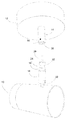
- FIG. 4 is a perspective view of another embodiment of the exchangeable head lighting unit in a detached position.
- FIG. 5 is a perspective view of the exchangeable head lighting unit of FIG. 4 in an attached position.
- FIG. 1 a is a view of the exchangeable head lighting system of the invention mounted on a single canopy and attached to a track lighting system.
- Canopy 12 is configured to receive electrical power from, and be supported by, an electrified track 8 .
- Canopy 12 includes support post 14 , which is a female component of a bayonet-style connector.
- Exchangeable lighting head 10 is attached to connecting post 18 .
- the exchangeable lighting head 10 has at least one light source 20 .
- the light source 20 may be, for example, a spotlamp, floodlamp, fluorescent bulb, LED, or other illuminating device known to those of skill in the art.
- Connecting post 18 has a portion having a reduced diameter 16 which its into support post 14 . As depicted in FIG. 1 a , connecting post 18 and support post 14 are slightly apart from a secure attachment. When securely attached, reduced diameter portion 16 will be within support post 14 , will not be visible.
- FIG. 1 b shows the fixture of FIG. 1 mounted on a vertically oriented surface in which in-wall wiring extends through the wall and is connected to the unit behind the canopy 12 .
- FIG. 1 c is a view of the exchangeable head lighting system of the invention mounted on a single canopy 12 on a ceiling.
- FIG. 2 depicts the components shown in FIG. 1 in a detached position.
- Support post 14 has a hole 30 to receive a set screw or other tightening mechanism that will fit within waist portion 24 of connecting post 18 to secure exchangeable lighting head 10 within support post 14 .
- Cavity 28 receives electrical contact 26 and the reduced diameter portion 16 and 32 of connecting post 18 .
- Electrical connections within support post 14 and connecting post 18 may be of any conventional type of electrical bayonet-type connector as is well known in the art.
- Ball joint 22 at the lower end of connecting post 18 permits great flexibility and directional adjustment for exchangeable lighting head 10 .
- FIG. 3 shows two exchangeable lighting heads 10 having different shapes and that may have different functions, e.g., flood light or spot light. Both exchangeable lighting heads have an identical connecting post 18 with electrical contact 26 that will be received within cavity 28 of support post 14 on base 12 .
- FIGS. 4 and 5 show another embodiment of the exchangeable head lighting unit in detached and attached positions, respectively.
- Support post 14 may also include an inner sleeve 34 , an inner electrical contact 36 , a recess 38 , and a wire 40 .
- the inner sleeve 34 may be configured to receive the reduced diameter portions 16 , 32 of the connecting post 18 .
- Reduced diameter portion 32 may carry a friction fit spring clip of greater diameter than the inner sleeve 34 . As those in the art will appreciate, this may assist securing the connecting post 18 to the support post 14 .
- the inner sleeve 34 may be electrically grounded and provide a return path for electric current flowing to the exchangeable lighting head 10 .
- the inner electrical contact 36 may be configured to receive electrical contact 26 , for example, a female-style bayonet electrical contact with a recess 38 .
- the wire 40 may be connected to the inner electrical contact 36 to provide electrical power to the system.
- the wire 40 may carry 12 volts.
- the exchangeable head lighting unit may include a step-down transformer to convert high voltage alternating current to low voltage direct current.
- the step-down transformer may be arranged, for example, in the support post 14 or the canopy 12 .
Landscapes
- Engineering & Computer Science (AREA)
- General Engineering & Computer Science (AREA)
- Architecture (AREA)
- Non-Portable Lighting Devices Or Systems Thereof (AREA)
Abstract
Description
Claims (14)
Priority Applications (3)
| Application Number | Priority Date | Filing Date | Title |
|---|---|---|---|
| US14/460,746 US9739460B2 (en) | 2013-08-15 | 2014-08-15 | Interchangeable lighting fixtures for track and wall lighting system |
| CA2859584A CA2859584A1 (en) | 2013-08-15 | 2014-08-15 | Interchangeable lighting fixtures for track and wall lighting system |
| US15/465,828 US20170191643A1 (en) | 2013-08-15 | 2017-03-22 | Interchangeable lighting fixtures for track and wall lighting system |
Applications Claiming Priority (2)
| Application Number | Priority Date | Filing Date | Title |
|---|---|---|---|
| US201361866317P | 2013-08-15 | 2013-08-15 | |
| US14/460,746 US9739460B2 (en) | 2013-08-15 | 2014-08-15 | Interchangeable lighting fixtures for track and wall lighting system |
Related Child Applications (1)
| Application Number | Title | Priority Date | Filing Date |
|---|---|---|---|
| US15/465,828 Continuation US20170191643A1 (en) | 2013-08-15 | 2017-03-22 | Interchangeable lighting fixtures for track and wall lighting system |
Publications (2)
| Publication Number | Publication Date |
|---|---|
| US20150049513A1 US20150049513A1 (en) | 2015-02-19 |
| US9739460B2 true US9739460B2 (en) | 2017-08-22 |
Family
ID=52466712
Family Applications (2)
| Application Number | Title | Priority Date | Filing Date |
|---|---|---|---|
| US14/460,746 Active 2035-08-17 US9739460B2 (en) | 2013-08-15 | 2014-08-15 | Interchangeable lighting fixtures for track and wall lighting system |
| US15/465,828 Abandoned US20170191643A1 (en) | 2013-08-15 | 2017-03-22 | Interchangeable lighting fixtures for track and wall lighting system |
Family Applications After (1)
| Application Number | Title | Priority Date | Filing Date |
|---|---|---|---|
| US15/465,828 Abandoned US20170191643A1 (en) | 2013-08-15 | 2017-03-22 | Interchangeable lighting fixtures for track and wall lighting system |
Country Status (2)
| Country | Link |
|---|---|
| US (2) | US9739460B2 (en) |
| CA (1) | CA2859584A1 (en) |
Cited By (11)
| Publication number | Priority date | Publication date | Assignee | Title |
|---|---|---|---|---|
| US20160215964A1 (en) * | 2015-01-26 | 2016-07-28 | Feit Electric Company, Inc. | Customizable Stand Lamp |
| US20180058675A1 (en) * | 2016-01-07 | 2018-03-01 | Robert A. Sonneman | Modular lighting system using hangers and power bars |
| US10041662B2 (en) | 2016-11-09 | 2018-08-07 | Robert A. Sonneman | Light bar for a lighting system |
| US10151466B2 (en) | 2016-11-09 | 2018-12-11 | Contemporary Visions, LLC | Laterally supported lights |
| US10174923B2 (en) | 2016-11-09 | 2019-01-08 | Contemporary Visions, LLC | Hanger for a modular lighting system having a main body with two channels to accommodate two segments of a power bar |
| US10184645B2 (en) | 2016-11-09 | 2019-01-22 | Contemporary Visions, LLC | Cylindrical housing for modular lighting system |
| US10281126B2 (en) | 2016-11-09 | 2019-05-07 | Contemporary Visions, LLC | Power bar hanger for modular lighting system |
| US10359182B2 (en) | 2016-11-09 | 2019-07-23 | Contemporary Visions, LLC | Ring power bar hanger for modular lighting fixture |
| US10670203B1 (en) | 2019-06-10 | 2020-06-02 | Inter-Global, Inc. | Modular light fixture with interchangeable components |
| US10985478B1 (en) * | 2018-02-17 | 2021-04-20 | Lumenture, LLC | Low profile lighting adapters |
| USD966601S1 (en) | 2019-02-19 | 2022-10-11 | Lumenture, Inc. | Lighting track adapter |
Families Citing this family (14)
| Publication number | Priority date | Publication date | Assignee | Title |
|---|---|---|---|---|
| USD779696S1 (en) * | 2002-01-07 | 2017-02-21 | The L.D. Kichler Co. | Lighting fixture |
| USD754905S1 (en) * | 2014-03-21 | 2016-04-26 | Iguzzini Illuminazione S.P.A. | Lighting fixture |
| CN105485575A (en) * | 2016-01-11 | 2016-04-13 | 何慧敏 | Adjustable bridge decorative lamp mounting device |
| CN105588083B (en) * | 2016-01-28 | 2019-01-22 | 傅文华 | Separate type rail joint structure |
| CN105927938B (en) * | 2016-06-17 | 2023-05-02 | 欧普照明股份有限公司 | Lighting device |
| US9929524B1 (en) | 2016-06-24 | 2018-03-27 | Matthew Rodgers | System and articles of interchangeably connectable pre-wired segments |
| US10401008B2 (en) * | 2017-02-01 | 2019-09-03 | Ideal Industries Lighting Llc | Track lighting fixtures and application thereof |
| US10330295B1 (en) * | 2017-12-18 | 2019-06-25 | Alan K. Uke | Swivel lamp |
| CN108709126B (en) * | 2018-07-12 | 2024-03-01 | 刘洁 | Energy-saving lamp with lamp cap and lamp tube capable of being replaced respectively |
| CN209084502U (en) * | 2018-08-18 | 2019-07-09 | 东莞市兆合智能照明有限公司 | A kind of modular guidng rail lamp of Quick Release fast-assembling |
| US11209137B2 (en) * | 2019-05-08 | 2021-12-28 | Xiamen Eco Lighting Co. Ltd. | Spot downlight apparatus |
| CN110081347A (en) * | 2019-05-25 | 2019-08-02 | 青岛农业大学 | A kind of adjoint stage lighting of the intelligence of video display engineering |
| US11118762B1 (en) * | 2020-09-14 | 2021-09-14 | Shenzhen Yuytyuan Technology Co., Ltd | Lamp |
| US11976805B1 (en) * | 2023-08-18 | 2024-05-07 | Giantech Industries Co., Ltd. | Connection structure of LED wall lamp having hidden switch |
Citations (1)
| Publication number | Priority date | Publication date | Assignee | Title |
|---|---|---|---|---|
| US5788518A (en) * | 1997-03-31 | 1998-08-04 | Juno Lighting, Inc. | Adjustable connector for track lighting fixture |
-
2014
- 2014-08-15 CA CA2859584A patent/CA2859584A1/en not_active Abandoned
- 2014-08-15 US US14/460,746 patent/US9739460B2/en active Active
-
2017
- 2017-03-22 US US15/465,828 patent/US20170191643A1/en not_active Abandoned
Patent Citations (1)
| Publication number | Priority date | Publication date | Assignee | Title |
|---|---|---|---|---|
| US5788518A (en) * | 1997-03-31 | 1998-08-04 | Juno Lighting, Inc. | Adjustable connector for track lighting fixture |
Cited By (21)
| Publication number | Priority date | Publication date | Assignee | Title |
|---|---|---|---|---|
| US20160215964A1 (en) * | 2015-01-26 | 2016-07-28 | Feit Electric Company, Inc. | Customizable Stand Lamp |
| US10203100B2 (en) | 2016-01-07 | 2019-02-12 | Contemporary Visions, LLC | Method and apparatus for hanging lighting fixtures |
| US20180058675A1 (en) * | 2016-01-07 | 2018-03-01 | Robert A. Sonneman | Modular lighting system using hangers and power bars |
| US20180066831A1 (en) * | 2016-01-07 | 2018-03-08 | Robert A. Sonneman | Canopy for a modular lighting system |
| US10018339B2 (en) | 2016-01-07 | 2018-07-10 | Robert A. Sonneman | Modular lighting system using hangers and power bars |
| US10036541B2 (en) | 2016-01-07 | 2018-07-31 | Contemporary Visions, LLC | Canopy for a modular lighting system |
| US10527269B2 (en) | 2016-01-07 | 2020-01-07 | Contemporary Visions, LLC | Modular lighting system using hangers and power bars |
| US10060609B2 (en) | 2016-01-07 | 2018-08-28 | Contemporary Visions, LLC | Modular lighting system using hangers and power bars |
| US10151465B2 (en) | 2016-01-07 | 2018-12-11 | Contemporary Visions, LLC | Modular lighting system with a plurality of power bars |
| US10288271B2 (en) * | 2016-01-07 | 2019-05-14 | Contemporary Visions, LLC | Canopy for a modular lighting system |
| US10156349B2 (en) | 2016-01-07 | 2018-12-18 | Contemporary Visions, LLC | Method and apparatus for hanging lighting fixtures |
| US10174923B2 (en) | 2016-11-09 | 2019-01-08 | Contemporary Visions, LLC | Hanger for a modular lighting system having a main body with two channels to accommodate two segments of a power bar |
| US10184645B2 (en) | 2016-11-09 | 2019-01-22 | Contemporary Visions, LLC | Cylindrical housing for modular lighting system |
| US10281126B2 (en) | 2016-11-09 | 2019-05-07 | Contemporary Visions, LLC | Power bar hanger for modular lighting system |
| US10151466B2 (en) | 2016-11-09 | 2018-12-11 | Contemporary Visions, LLC | Laterally supported lights |
| US10359182B2 (en) | 2016-11-09 | 2019-07-23 | Contemporary Visions, LLC | Ring power bar hanger for modular lighting fixture |
| US10041662B2 (en) | 2016-11-09 | 2018-08-07 | Robert A. Sonneman | Light bar for a lighting system |
| US10985478B1 (en) * | 2018-02-17 | 2021-04-20 | Lumenture, LLC | Low profile lighting adapters |
| US11658428B1 (en) | 2018-02-17 | 2023-05-23 | Lumenture, Inc. | Low profile lighting adapters |
| USD966601S1 (en) | 2019-02-19 | 2022-10-11 | Lumenture, Inc. | Lighting track adapter |
| US10670203B1 (en) | 2019-06-10 | 2020-06-02 | Inter-Global, Inc. | Modular light fixture with interchangeable components |
Also Published As
| Publication number | Publication date |
|---|---|
| US20150049513A1 (en) | 2015-02-19 |
| US20170191643A1 (en) | 2017-07-06 |
| CA2859584A1 (en) | 2015-02-15 |
Similar Documents
| Publication | Publication Date | Title |
|---|---|---|
| US9739460B2 (en) | Interchangeable lighting fixtures for track and wall lighting system | |
| USRE48264E1 (en) | Power delivery system for HID, LED, or fluorescent track lighting | |
| JP6881779B2 (en) | Connector system for lighting assembly | |
| US10203100B2 (en) | Method and apparatus for hanging lighting fixtures | |
| JP6165832B2 (en) | Line-type lighting device (LINETYPIGHTINGGAPPPARATUS) | |
| US9976712B2 (en) | Lamp for use in a lighting strip system and lighting strip system | |
| KR101622022B1 (en) | Line type lighting apparatus | |
| US8950909B2 (en) | Light fixture with concealed wireway | |
| KR20070119128A (en) | Sticking type lighting device with magnet | |
| KR102032908B1 (en) | Multi Connector of Righting Bushway | |
| KR102606223B1 (en) | Line type magnetic LED lighting apparatus | |
| CN105281163B (en) | A kind of adapter assembly | |
| US20140126194A1 (en) | Straight tube luminaire | |
| KR101559134B1 (en) | LED lighting appratus that is easy to adjust the angle of rotation | |
| JP5455951B2 (en) | Lamp and lighting device using the lamp | |
| US11004584B2 (en) | Electric track system for various appliances via magnetic positioning | |
| KR101370092B1 (en) | Mounting device for led lighting lamp | |
| CN108426209B (en) | Light emitting module, lighting device and ceiling lamp | |
| KR20090005498A (en) | Device for wiring cable and lighting system with the same | |
| CA2991974C (en) | Modular lighting system using hangers and power bars | |
| KR101627495B1 (en) | Retrofit type led lamp with separation structure of socket part | |
| KR101327170B1 (en) | Lighting device | |
| KR101195845B1 (en) | Socket for led lamp | |
| CN214425798U (en) | Split type high waterproof type LED projecting lamp | |
| JP6913934B2 (en) | LED lamp set |
Legal Events
| Date | Code | Title | Description |
|---|---|---|---|
| AS | Assignment |
Owner name: THE PRIVATEBANK AND TRUST COMPANY, ILLINOIS Free format text: SECURITY INTEREST;ASSIGNORS:EVOLUTION LIGHTING, LLC;ELECTRIX, LLC;REEL/FRAME:040761/0062 Effective date: 20161223 |
|
| AS | Assignment |
Owner name: EVOLUTION LIGHTING, LLC, FLORIDA Free format text: ASSIGNMENT OF ASSIGNORS INTEREST;ASSIGNOR:HAUBACH, TIMOTHY J;REEL/FRAME:043051/0172 Effective date: 20170714 |
|
| STCF | Information on status: patent grant |
Free format text: PATENTED CASE |
|
| AS | Assignment |
Owner name: EVOLUTION LIGHTING, LLC, FLORIDA Free format text: PARTIAL RELEASE OF SECURITY INTEREST IN PATENTS;ASSIGNOR:CIBC BANK USA (FORMERLY KNOWN AS THE PRIVATEBANK AND TRUST COMPANY);REEL/FRAME:052585/0254 Effective date: 20200504 |
|
| AS | Assignment |
Owner name: 3336820 NOVA SCOTIA LIMITED, CANADA Free format text: ASSIGNMENT OF ASSIGNORS INTEREST;ASSIGNORS:EVOLUTION LIGHTING, LLC;EVOLUTION LIGHTING CANADA, INC.;EVOLUTION LIGHTING (ASIA), LTD.;REEL/FRAME:053482/0563 Effective date: 20200504 Owner name: LUCIDITY LIGHTS, INC., MASSACHUSETTS Free format text: ASSIGNMENT OF ASSIGNORS INTEREST;ASSIGNORS:EVOLUTION LIGHTING, LLC;EVOLUTION LIGHTING CANADA, INC.;EVOLUTION LIGHTING (ASIA), LTD.;REEL/FRAME:053482/0563 Effective date: 20200504 |
|
| MAFP | Maintenance fee payment |
Free format text: PAYMENT OF MAINTENANCE FEE, 4TH YR, SMALL ENTITY (ORIGINAL EVENT CODE: M2551); ENTITY STATUS OF PATENT OWNER: SMALL ENTITY Year of fee payment: 4 |
|
| AS | Assignment |
Owner name: ELECTRIX LLC, FLORIDA Free format text: RELEASE BY SECURED PARTY;ASSIGNOR:CIBC BANK, USA F/K/A THE PRIVATE BANK AND TRUST COMPANY;REEL/FRAME:055932/0771 Effective date: 20210414 Owner name: EVOLUTION LIGHTING , LLC, FLORIDA Free format text: RELEASE BY SECURED PARTY;ASSIGNOR:CIBC BANK, USA F/K/A THE PRIVATE BANK AND TRUST COMPANY;REEL/FRAME:055932/0771 Effective date: 20210414 |