US9723033B2 - Router - Google Patents
Router Download PDFInfo
- Publication number
- US9723033B2 US9723033B2 US14/733,936 US201514733936A US9723033B2 US 9723033 B2 US9723033 B2 US 9723033B2 US 201514733936 A US201514733936 A US 201514733936A US 9723033 B2 US9723033 B2 US 9723033B2
- Authority
- US
- United States
- Prior art keywords
- wireless access
- access point
- signal transceiver
- base station
- router
- Prior art date
- Legal status (The legal status is an assumption and is not a legal conclusion. Google has not performed a legal analysis and makes no representation as to the accuracy of the status listed.)
- Active, expires
Links
Images


Classifications
-
- H—ELECTRICITY
- H04—ELECTRIC COMMUNICATION TECHNIQUE
- H04L—TRANSMISSION OF DIGITAL INFORMATION, e.g. TELEGRAPHIC COMMUNICATION
- H04L65/00—Network arrangements, protocols or services for supporting real-time applications in data packet communication
- H04L65/1066—Session management
- H04L65/1069—Session establishment or de-establishment
-
- H—ELECTRICITY
- H04—ELECTRIC COMMUNICATION TECHNIQUE
- H04L—TRANSMISSION OF DIGITAL INFORMATION, e.g. TELEGRAPHIC COMMUNICATION
- H04L65/00—Network arrangements, protocols or services for supporting real-time applications in data packet communication
- H04L65/1066—Session management
- H04L65/1101—Session protocols
- H04L65/1104—Session initiation protocol [SIP]
-
- H—ELECTRICITY
- H04—ELECTRIC COMMUNICATION TECHNIQUE
- H04W—WIRELESS COMMUNICATION NETWORKS
- H04W40/00—Communication routing or communication path finding
-
- H—ELECTRICITY
- H04—ELECTRIC COMMUNICATION TECHNIQUE
- H04W—WIRELESS COMMUNICATION NETWORKS
- H04W80/00—Wireless network protocols or protocol adaptations to wireless operation
- H04W80/08—Upper layer protocols
- H04W80/10—Upper layer protocols adapted for application session management, e.g. SIP [Session Initiation Protocol]
-
- H—ELECTRICITY
- H04—ELECTRIC COMMUNICATION TECHNIQUE
- H04W—WIRELESS COMMUNICATION NETWORKS
- H04W84/00—Network topologies
- H04W84/02—Hierarchically pre-organised networks, e.g. paging networks, cellular networks, WLAN [Wireless Local Area Network] or WLL [Wireless Local Loop]
- H04W84/10—Small scale networks; Flat hierarchical networks
- H04W84/12—WLAN [Wireless Local Area Networks]
-
- H—ELECTRICITY
- H04—ELECTRIC COMMUNICATION TECHNIQUE
- H04W—WIRELESS COMMUNICATION NETWORKS
- H04W88/00—Devices specially adapted for wireless communication networks, e.g. terminals, base stations or access point devices
- H04W88/08—Access point devices
- H04W88/10—Access point devices adapted for operation in multiple networks, e.g. multi-mode access points
Definitions
- the present invention generally relates a router, in particular, to a router and a wireless access point capable of providing good communication quality
- LTE Long-Term Evolution
- LTE for wireless communication is convenient to use without physical wiring. Therefore, it becomes popular and preferred communication connection mean of users under considerations of cost, connection speed and convenience.
- a LTE router For setting up a communication between a user terminal and a based station via LTE, a LTE router is necessary.
- the conventional LTE router is usually arranged indoors.
- the LTE router arranged indoors may be equipped with an indoor antenna for transceiving data and voice signals.
- the communication quality of indoor antenna is relatively poor.
- the present invention is directed to a router capable of providing good communication quality.
- An exemplary embodiment of the invention provides a router including a processor, a wide area network (WAN) signal transceiver, and a local area network (LAN) signal transceiver.
- the WAN signal transceiver is controlled by the processor and configured to transceive the voice and data signals with a base station via a telecommunication network.
- the LAN signal transceiver is controlled by the processor and configured to transceive the voice and data signals with a wireless access point via a local area network.
- a voice conversation between the wireless access point and the base station is conducted through the router, so that good signal quality is provided during the voice conversation.
- FIG. 2 illustrates a block diagram of the two wireless access points according to an exemplary embodiment of the invention.
- FIG. 3 is a time flowchart illustrating a voice conversation between the base station and the second wireless access point through the first wireless access point according to an exemplary embodiment of the invention.
- FIG. 4 illustrates a wireless network architecture according to another exemplary embodiment of the invention.
- FIG. 5 is a time flowchart illustrating a voice conversation between the base station and the second wireless access point through the first wireless access point according to another exemplary embodiment of the invention.
- FIG. 6 illustrates a wireless network architecture according to another exemplary embodiment of the invention.
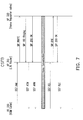
- FIG. 7 is a time flowchart illustrating a voice conversation between the base station and the second wireless access point through the first wireless access point according to another exemplary embodiment of the invention.
- FIG. 8 illustrates a wireless network architecture according to another exemplary embodiment of the invention.
- FIG. 9 is a time flowchart illustrating a voice conversation between the base station and the second wireless access point through the first wireless access point according to another exemplary embodiment of the invention.
- FIG. 1 illustrates a wireless network architecture according to an exemplary embodiment of the invention.
- the wireless network architecture 100 mainly includes a first wireless access point 110 , a second wireless access point 120 and a based station 130 .
- the first wireless access point 110 may be a router, and the second wireless access point 120 may be a router, a repeater or an adapter.
- the first wireless access point 110 and the second wireless access point 120 may be deemed as a communication system, and voice/data conversation may be conducted therebetween, for example.
- the repeater is exemplary for the second wireless access point 120 in the disclosure, but the invention is not limited thereto.
- the first wireless access point 110 may also communicate with more than one second wireless access points, such as multiple repeaters in another exemplary embodiment.
- FIG. 2 illustrates a block diagram of the two wireless access points according to an exemplary embodiment of the disclosure.
- the first wireless access point 110 depicted in FIG. 2 may be a router and includes a processor 112 , a wide area network (WAN) signal transceiver 114 , and a local area network (LAN) signal transceiver 116 in this exemplary embodiment.
- the processor 112 , the WAN signal transceiver 114 , and the LAN signal transceiver 116 are separately configured in the first wireless access point 110 , but is not limited thereto.
- the processor 112 , the WAN signal transceiver 114 , and the LAN signal transceiver 116 may also be combined in the same chipset.
- the first wireless access point 110 may further include the functional elements such as a calculation module, a storage module, a communication module and a power module. Since these elements are well known by persons having ordinary skill in the art, they are not described for a concise purpose.
- the processor 112 is configured to control the WAN signal transceiver 114 and the LAN signal transceiver 116 , so as to allow the first wireless access point 110 to communicate with the base station 130 and the second wireless access point 120 respectively.
- the WAN signal transceiver 114 transceives voice signals and data signals with the base station 130 via a telecommunication network.
- the LAN signal transceiver 116 transceives the voice signals and the data signals with the second wireless access point 120 via a local area network (LAN).
- LAN local area network
- the LAN signal transceiver 116 transceives the voice signals and the data signals with the second wireless access point 120 over a first communication standard, such as wireless fidelity (WiFi) communication protocol.
- the WAN signal transceiver 114 transceives the voice signals and the data signals with the base station 130 over a second communication standard, such as LTE communication protocol. That is to say, the first wireless access point 110 conducts a voice conversation between the second wireless access point 120 and the base station 130 by using voice over LTE (VoLTE) technology, for example.
- VoIP voice over LTE
- the second wireless access point 120 is similar to the first wireless access point 110 and may at least include a processor 122 and a LAN signal transceiver 126 for communicating with the first wireless access point 110 .
- the second wireless access point 120 may further include a WAN signal transceiver 124 .
- the LAN signal transceiver 126 of the second wireless access point 120 is controlled by the processor 122 thereof.
- the LAN signal transceiver 126 is configured to transceive voice signals and data signals with the first wireless access point 110 via the local area network, and transceive the voice signals and the data signals with the base station 130 via the telecommunication network through the first wireless access point 110 .
- the second wireless access point 120 may at least transmit the voice signals to one or multiple user terminals 140 that are capable of parsing the voice signals, such as indoor phones or portable electronic devices including software phone app, notebook computers, tablet computers, smart phones, smart watches and etc.
- the second wireless access point 120 and the user terminals 140 may be integrated to single device by adding SLIC modules or DECT modules.
- FIG. 3 is a time flowchart illustrating a voice conversation between the base station and the second wireless access point through the first wireless access point according to an exemplary embodiment.
- the processor 112 performs a signalling procedure with the base station 130 and the second wireless access point 120 before the voice conversation is conducted.
- the processor 112 performs the signalling procedure via the WAN signal transceiver 114 to set up a first communication between the first wireless access point 110 , i.e. the router, and the base station 130 by session initiation protocol (SIP).
- SIP session initiation protocol
- the processor 112 also performs the signalling procedure via the LAN signal transceiver 116 to set up a second communication between the first wireless access point 110 and the second wireless access point 120 by at least one of VoIP protocols such as SIP, xGCP, or XMPP.
- VoIP protocols such as SIP, xGCP, or XMPP.
- the first wireless access point 110 receives SIP messages from the base station 130 and transmits the received SIP messages to the second wireless access point 120 .
- the first wireless access point 110 receives the SIP messages responded from the second wireless access point 120 and transmits the received SIP messages back to the base station 130 .
- the first and the second communication are set up, and thus the voice conversation may be conducted. After the voice conversation is finished, the first and the second communication are disconnected.
- the SIP messages includes messages SIP INVITE, SIP 180 Ringing, SIP 200 OK, SIP ACK, and SIP BYE that comply with SIP, which is not limited thereto.
- the first wireless access point 110 for example, communicates with the single second wireless access point 120 , which is not limited thereto.
- the first wireless access point 110 may transmit the voice signals to multiple second wireless access points 120 .
- FIG. 4 illustrates a wireless network architecture according to another exemplary embodiment.
- FIG. 5 is a time flowchart illustrating a voice conversation between the base station and the second wireless access point through the first wireless access point according to another exemplary embodiment.
- the first wireless access point 210 receives voice signals from the base station 230 to set up the first voice conversation with the base station 230 , and prompts the users in base station 230 side to dial an extension number. After receives the extension number, the first wireless access point 210 sends voice signals to at the least one of the multiple wireless access point 220 - 1 to 220 -N and set up the second voice conversation. In the meantime, the first wireless access point 210 bridges the voice conversation between first voice conversation and second voice conversation.
- the first wireless access point 210 receives SIP request messages from the base station 230 and transmits the SIP responding messages back to the base station 230 , so as to set up the first voice conversation.
- the first wireless access point 210 prompts the users in base station 230 side to dial an extension number.
- the first wireless access points After recognize the extension number by dual-tone multi-frequency (DTMF) signalling, e.g. 220 - 1 , the first wireless access points transmit voice signals to selected second wireless access points 220 - 1 to set up the second voice conversation.
- DTMF dual-tone multi-frequency
- the processor of the first wireless access point 210 respectively performs the signalling procedure with the base station 230 and the selected second wireless access point 220 - 1 by at least one of VoIP protocols, such as SIP, xGCP, or XMPP, via the WAN signal transceiver and the LAN signal transceiver of the first wireless access point 210 to set up the first communication between the first wireless access point 210 and the base station 230 and the second communication between the first wireless access point 210 and the second wireless access point 220 - 1 .
- VoIP protocols such as SIP, xGCP, or XMPP
- FIG. 6 illustrates a wireless network architecture according to another exemplary embodiment.
- FIG. 7 is a time flowchart illustrating a voice conversation between the base station and the second wireless access point through the first wireless access point according to another exemplary embodiment.
- the processor of the first wireless access point 310 controls the LAN signal transceiver thereof to transceive the voice signals and the data signals with the second wireless access point over a first communication standard, e.g. WiFi communication protocol.
- a first communication standard e.g. WiFi communication protocol.
- the processor of the first wireless access point 310 controls the WAN signal transceiver thereof to transceive the data signals with the base station 330 over a second communication standard, e.g. LTE communication protocol, and transceive the voice signals with the base station 330 over a third communication standard, e.g. the standard of global system for mobile communications (GSM) or the standard of wideband code division multiple access (WCDMA). That is to say, the first wireless access point 310 conducts a voice conversation between the second wireless access point 320 and the base station 330 by circuit switched fallback (CSFB) technology, for example.
- GSM global system for mobile communications
- WCDMA wideband code division multiple access
- the processor of the first wireless access point 310 performs a signalling procedure with the base station 330 and the second wireless access point 320 before the voice conversation is conducted as shown in FIG. 7 .
- the processor of the first wireless access point 310 performs the signalling procedure via the WAN signal transceiver thereof to set up a first communication between the first wireless access point 310 , i.e. the router, and the base station 330 by signalling system No. 7 (SS7).
- the processor of the first wireless access point 310 performs the signalling procedure via the LAN signal transceiver thereof to set up a second communication between the first wireless access point 310 and the second wireless access point 320 by at least one of VoIP protocols.
- the first and the second communication are set up based on different protocols in this exemplary embodiment.
- the first wireless access point 310 receives SS7 messages from the base station 330 and converts the received SS7 messages to SIP messages. After conversion, the first wireless access point 310 transmits the SIP messages to the second wireless access point 320 . Next, the first wireless access point 310 receives and converts the SIP messages responded from the second wireless access point 320 , and then transmits the SS7 messages back to the base station 330 . In this manner, the first and the second communication are set up, and thus the voice conversation may be conducted. After the voice conversation is finished, the first and the second communication connections are disconnected.
- the SIP messages includes messages SIP INVITE, SIP 180 Ringing, SIP 200 OK, SIP ACK, and SIP BYE that comply with SIP
- the SS7 messages includes messages SS7 IAM, SS7 ACM, SS7 REL, and SS7 RLC that comply with SS7, which is not limited thereto.
- FIG. 8 illustrates a wireless network architecture according to another exemplary embodiment.
- FIG. 9 is a time flowchart illustrating a voice conversation between the base station and the second wireless access point through the first wireless access point according to another exemplary embodiment.
- the first wireless access point 410 receives voice signals from the base station 430 to set up the first voice conversation with base station 430 , and prompts the users in base station 430 side to dial an extension number in the first voice conversation. After receives the extension number, the first wireless access point 410 sends voice signals to at the least one of the multiple wireless access point 420 - 1 to 420 -N and set up the second voice conversation.
- the first wireless access point 410 bridges the voice conversation between first voice conversation and second voice conversation.
- the first wireless access point 410 set up the first voice conversation with base station by receiving SS7 signals and prompts the users in base station 430 side to dial an extension number.
- the first wireless access points After recognize the extension number by dual-tone multi-frequency (DTMF) signalling, e.g. 420 - 1 , the first wireless access points transmit voice signals to the selected second wireless access points 420 - 1 to set up the second voice conversation.
- DTMF dual-tone multi-frequency
- the first wireless access point transceives voice signals and data signals with the base station via the telecommunication network.
- the first wireless access point transceives the voice signals and the data signals with the second wireless access point via the local area network. Accordingly, the voice conversation between the base station and the second wireless access point is conducted through the first wireless access point, and thus good signal quality is provided during the voice conversation.
Landscapes
- Engineering & Computer Science (AREA)
- Computer Networks & Wireless Communication (AREA)
- Signal Processing (AREA)
- Business, Economics & Management (AREA)
- General Business, Economics & Management (AREA)
- Multimedia (AREA)
- Mobile Radio Communication Systems (AREA)
Abstract
A router including a processor, a wide area network (WAN) signal transceiver, and a local area network (LAN) is provided. The WAN signal transceiver is controlled by the processor. The WAN signal transceiver is configured to transceive voice signals and data signals with a base station via a telecommunication network. The LAN signal transceiver is controlled by the processor. The LAN signal transceiver is configured to transceive the voice signals and the data signals with a wireless access point via a local area network.
Description
1. Field of the Invention
The present invention generally relates a router, in particular, to a router and a wireless access point capable of providing good communication quality
2. Description
Long-Term Evolution (LTE) is a standard for wireless communication of high-speed data for mobile phones and data terminals. Transmission speed and stability of LTE are improved as related technology improves continuously. Furthermore, LTE for wireless communication is convenient to use without physical wiring. Therefore, it becomes popular and preferred communication connection mean of users under considerations of cost, connection speed and convenience.
For setting up a communication between a user terminal and a based station via LTE, a LTE router is necessary. The conventional LTE router is usually arranged indoors. The LTE router arranged indoors may be equipped with an indoor antenna for transceiving data and voice signals. However, the communication quality of indoor antenna is relatively poor.
Accordingly, the present invention is directed to a router capable of providing good communication quality.
An exemplary embodiment of the invention provides a router including a processor, a wide area network (WAN) signal transceiver, and a local area network (LAN) signal transceiver. The WAN signal transceiver is controlled by the processor and configured to transceive the voice and data signals with a base station via a telecommunication network. The LAN signal transceiver is controlled by the processor and configured to transceive the voice and data signals with a wireless access point via a local area network.
Based on above, in the exemplary embodiments of the invention, a voice conversation between the wireless access point and the base station is conducted through the router, so that good signal quality is provided during the voice conversation.
To make the above features and advantages of the disclosure more comprehensible, several embodiments accompanied with drawings are described in detail as follows.
The accompanying drawings are included to provide a further understanding of the invention, and are incorporated in and constitute a part of this specification. The drawings illustrate embodiments of the invention and, together with the description, serve to explain the principles of the invention.
Reference will now be made in detail to the present preferred embodiments of the invention, examples of which are illustrated in the accompanying drawings. Wherever possible, the same reference numbers are used in the drawings and the description to refer to the same or like parts.
In this exemplary embodiment, the processor 112 is configured to control the WAN signal transceiver 114 and the LAN signal transceiver 116, so as to allow the first wireless access point 110 to communicate with the base station 130 and the second wireless access point 120 respectively. To be specific, the WAN signal transceiver 114 transceives voice signals and data signals with the base station 130 via a telecommunication network. The LAN signal transceiver 116 transceives the voice signals and the data signals with the second wireless access point 120 via a local area network (LAN). In this exemplary embodiment, via the local area network, the LAN signal transceiver 116 transceives the voice signals and the data signals with the second wireless access point 120 over a first communication standard, such as wireless fidelity (WiFi) communication protocol. By contrast, via the telecommunication network, the WAN signal transceiver 114 transceives the voice signals and the data signals with the base station 130 over a second communication standard, such as LTE communication protocol. That is to say, the first wireless access point 110 conducts a voice conversation between the second wireless access point 120 and the base station 130 by using voice over LTE (VoLTE) technology, for example.
In this exemplary embodiment, the second wireless access point 120 is similar to the first wireless access point 110 and may at least include a processor 122 and a LAN signal transceiver 126 for communicating with the first wireless access point 110. For a router, the second wireless access point 120 may further include a WAN signal transceiver 124. The LAN signal transceiver 126 of the second wireless access point 120 is controlled by the processor 122 thereof. The LAN signal transceiver 126 is configured to transceive voice signals and data signals with the first wireless access point 110 via the local area network, and transceive the voice signals and the data signals with the base station 130 via the telecommunication network through the first wireless access point 110. In this exemplary embodiment, after receiving the voice signals and the data signals from the first wireless access point 110, the second wireless access point 120 may at least transmit the voice signals to one or multiple user terminals 140 that are capable of parsing the voice signals, such as indoor phones or portable electronic devices including software phone app, notebook computers, tablet computers, smart phones, smart watches and etc. In another embodiment, the second wireless access point 120 and the user terminals 140 may be integrated to single device by adding SLIC modules or DECT modules.
In this exemplary embodiment, the processor of the first wireless access point 210 respectively performs the signalling procedure with the base station 230 and the selected second wireless access point 220-1 by at least one of VoIP protocols, such as SIP, xGCP, or XMPP, via the WAN signal transceiver and the LAN signal transceiver of the first wireless access point 210 to set up the first communication between the first wireless access point 210 and the base station 230 and the second communication between the first wireless access point 210 and the second wireless access point 220-1.
The wireless network architecture and the communication method described in this exemplary embodiment are sufficiently taught, suggested, and embodied in the embodiments illustrated in FIG. 1 to FIG. 3 , and therefore further description is omitted herein.
In this exemplary embodiment, the processor of the first wireless access point 310 performs a signalling procedure with the base station 330 and the second wireless access point 320 before the voice conversation is conducted as shown in FIG. 7 . In this exemplary embodiment, the processor of the first wireless access point 310 performs the signalling procedure via the WAN signal transceiver thereof to set up a first communication between the first wireless access point 310, i.e. the router, and the base station 330 by signalling system No. 7 (SS7). The processor of the first wireless access point 310 performs the signalling procedure via the LAN signal transceiver thereof to set up a second communication between the first wireless access point 310 and the second wireless access point 320 by at least one of VoIP protocols. Accordingly, the first and the second communication are set up based on different protocols in this exemplary embodiment. As shown in FIG. 7 , the first wireless access point 310 receives SS7 messages from the base station 330 and converts the received SS7 messages to SIP messages. After conversion, the first wireless access point 310 transmits the SIP messages to the second wireless access point 320. Next, the first wireless access point 310 receives and converts the SIP messages responded from the second wireless access point 320, and then transmits the SS7 messages back to the base station 330. In this manner, the first and the second communication are set up, and thus the voice conversation may be conducted. After the voice conversation is finished, the first and the second communication connections are disconnected. In this exemplary embodiment, as the signalling procedure is executed, converting one of the SIP messages and the SS7 messages to another one of the SIP messages and the SS7 messages is necessary for the first wireless access point 310. In this exemplary embodiment, the SIP messages includes messages SIP INVITE, SIP 180 Ringing, SIP 200 OK, SIP ACK, and SIP BYE that comply with SIP, and the SS7 messages includes messages SS7 IAM, SS7 ACM, SS7 REL, and SS7 RLC that comply with SS7, which is not limited thereto.
In this exemplary embodiment, the first wireless access point 310, for example, communicates with the single second wireless access point 320, which is not limited thereto. In another exemplary embodiment, the first wireless access point 310 may transmit the voice signals to multiple second wireless access points 320.
In this exemplary embodiment, the processor of the first wireless access point 410 performs the signalling procedure with the base station 430 by SS7 via the WAN signal transceiver thereof to set up the first communication between the first wireless access point 410 and the base station 430. By contrast, the processor of the first wireless access point 410 performs the signalling procedure with the second wireless access point 420-1 by SIP via the LAN signal transceiver thereof to set up the second communication between the first wireless access point 410 and the second wireless access point 420-1. Accordingly, the first and the second communication are set up based on distinct protocols in this exemplary embodiment.
Besides, the wireless network architecture and the communication method described in this exemplary embodiment are sufficiently taught, suggested, and embodied in the embodiments illustrated in FIG. 6 to FIG. 7 , and further description is omitted herein.
In sum, the first wireless access point transceives voice signals and data signals with the base station via the telecommunication network. The first wireless access point transceives the voice signals and the data signals with the second wireless access point via the local area network. Accordingly, the voice conversation between the base station and the second wireless access point is conducted through the first wireless access point, and thus good signal quality is provided during the voice conversation.
It will be apparent to those skilled in the art that various modifications and variations can be made to the structure of the present invention without departing from the scope or spirit of the invention. In view of the foregoing, it is intended that the present invention cover modifications and variations of this invention provided they fall within the scope of the following claims and their equivalents.
Claims (10)
1. A router, comprising:
a processor;
a wide area network (WAN) signal transceiver controlled by the processor and configured to transceive voice signals and data signals with a base station via a telecommunication network and, after a voice conversation between the base station and the WAN signal transceiver is set up, to prompt the base station to signal an extension number via dual-tone multi-frequency (DTMF) through the voice conversation; and
a local area network (LAN) signal transceiver controlled by the processor and configured to detect the extension number via DTMF signalling, to select a wireless access point from a plurality of candidate wireless access points according to the extension number, and to transceive the voice signals and the data signals with the wireless access point via a local area network.
2. The router according to claim 1 , wherein via the local area network, the processor controls the LAN signal transceiver to transceive the voice signals and the data signals with the wireless access point over a first communication standard.
3. The router according to claim 2 , wherein via the telecommunication network, the processor controls the WAN signal transceiver to transceive the data signals with the base station over a second communication standard and transceive the voice signals with the base station over a third communication standard.
4. The router according to claim 3 , wherein the processor performs a signalling procedure with the base station by a first protocol via the WAN signal transceiver to set up a first communication between the router and the base station, and the processor performs the signalling procedure with the wireless access point by a second protocol via the LAN signal transceiver to set up a second communication between the router and the wireless access point.
5. The router according to claim 4 , wherein when the first and the second communication set up, the processor conducts a first voice conversation between the base station and the router via the WAN signal transceiver.
6. The router according to claim 5 , wherein when the first communication sets up, the processor conducts a second voice conversation between the router and the wireless access point via the WAN signal transceiver and the LAN signal transceiver.
7. The router according to claim 4 , wherein the processor converts messages from a first format to a second format.
8. The router according to claim 2 , wherein via the telecommunication network, the processor controls the WAN signal transceiver to transceive the voice signals and the data signals with the base station over a second communication standard.
9. The router according to claim 8 , wherein the processor performs a signalling procedure with the base station and the wireless access point by at least one of VoIP protocols via the WAN signal transceiver and the LAN signal transceiver to set up a first communication between the router and the base station and a second communication between the router and the wireless access point.
10. The router according to claim 1 , wherein the wireless access point is a repeater or an adapter.
Priority Applications (1)
| Application Number | Priority Date | Filing Date | Title |
|---|---|---|---|
| US14/733,936 US9723033B2 (en) | 2015-06-08 | 2015-06-08 | Router |
Applications Claiming Priority (1)
| Application Number | Priority Date | Filing Date | Title |
|---|---|---|---|
| US14/733,936 US9723033B2 (en) | 2015-06-08 | 2015-06-08 | Router |
Publications (2)
| Publication Number | Publication Date |
|---|---|
| US20160359549A1 US20160359549A1 (en) | 2016-12-08 |
| US9723033B2 true US9723033B2 (en) | 2017-08-01 |
Family
ID=57452438
Family Applications (1)
| Application Number | Title | Priority Date | Filing Date |
|---|---|---|---|
| US14/733,936 Active 2035-07-21 US9723033B2 (en) | 2015-06-08 | 2015-06-08 | Router |
Country Status (1)
| Country | Link |
|---|---|
| US (1) | US9723033B2 (en) |
Cited By (1)
| Publication number | Priority date | Publication date | Assignee | Title |
|---|---|---|---|---|
| US10484967B2 (en) * | 2016-07-21 | 2019-11-19 | Huawei Technologies Co., Ltd. | Communication method, network device, and terminal device |
Families Citing this family (1)
| Publication number | Priority date | Publication date | Assignee | Title |
|---|---|---|---|---|
| JP2017046200A (en) * | 2015-08-27 | 2017-03-02 | 富士通株式会社 | Communication control device and transmission system |
Citations (7)
| Publication number | Priority date | Publication date | Assignee | Title |
|---|---|---|---|---|
| US6067351A (en) * | 1997-09-25 | 2000-05-23 | Alcatel | Method for preparing a terminal to be used in a system, and system, and terminal |
| US20090147772A1 (en) * | 2006-10-02 | 2009-06-11 | Prasad Rao | Systems and methods for providing presence information in communication |
| US20090161626A1 (en) * | 2007-12-19 | 2009-06-25 | Verizon Business Network Services Inc. | System and method for dual-mode handoff |
| US20100290390A1 (en) * | 2009-05-15 | 2010-11-18 | Novatel Wireless Inc. | Systems and methods for controlling device network access through a wireless router |
| TWI389522B (en) | 2008-11-05 | 2013-03-11 | Asustek Comp Inc | Wireless access point, wireless network structure, and method for establishing wireless structure |
| TW201328396A (en) | 2011-12-20 | 2013-07-01 | Avermedia Tech Inc | Wireless data distributor, network system and method for receiving video and audio streaming data and internet website data |
| US20140321298A1 (en) * | 2011-01-12 | 2014-10-30 | Adaptive Spectrum And Signal Alignment, Inc. | Systems and methods for jointly optimizing wan and lan network communications |
-
2015
- 2015-06-08 US US14/733,936 patent/US9723033B2/en active Active
Patent Citations (7)
| Publication number | Priority date | Publication date | Assignee | Title |
|---|---|---|---|---|
| US6067351A (en) * | 1997-09-25 | 2000-05-23 | Alcatel | Method for preparing a terminal to be used in a system, and system, and terminal |
| US20090147772A1 (en) * | 2006-10-02 | 2009-06-11 | Prasad Rao | Systems and methods for providing presence information in communication |
| US20090161626A1 (en) * | 2007-12-19 | 2009-06-25 | Verizon Business Network Services Inc. | System and method for dual-mode handoff |
| TWI389522B (en) | 2008-11-05 | 2013-03-11 | Asustek Comp Inc | Wireless access point, wireless network structure, and method for establishing wireless structure |
| US20100290390A1 (en) * | 2009-05-15 | 2010-11-18 | Novatel Wireless Inc. | Systems and methods for controlling device network access through a wireless router |
| US20140321298A1 (en) * | 2011-01-12 | 2014-10-30 | Adaptive Spectrum And Signal Alignment, Inc. | Systems and methods for jointly optimizing wan and lan network communications |
| TW201328396A (en) | 2011-12-20 | 2013-07-01 | Avermedia Tech Inc | Wireless data distributor, network system and method for receiving video and audio streaming data and internet website data |
Cited By (1)
| Publication number | Priority date | Publication date | Assignee | Title |
|---|---|---|---|---|
| US10484967B2 (en) * | 2016-07-21 | 2019-11-19 | Huawei Technologies Co., Ltd. | Communication method, network device, and terminal device |
Also Published As
| Publication number | Publication date |
|---|---|
| US20160359549A1 (en) | 2016-12-08 |
Similar Documents
| Publication | Publication Date | Title |
|---|---|---|
| CN103493521A (en) | Emergency call mode preference in wireless communication networks | |
| EP3282736A1 (en) | Lte cellular mobile network access system and corresponding communication method | |
| CN102833432B (en) | A kind of incoming call retransmission method, Apparatus and system | |
| US20180091656A1 (en) | Voice Gateway-based Communication Method | |
| EP2536117A1 (en) | Method and apparatus for establishing circuit switched link of wifi handheld equipment | |
| US9154932B2 (en) | Method for establishment of an emergency call | |
| CN110719371A (en) | Cross-device communication method, device, equipment and storage medium | |
| CN112788582A (en) | Emergency call method and device thereof | |
| CN102724203A (en) | Internet protocol (IP) call dialing method for intelligent terminal | |
| US9723033B2 (en) | Router | |
| US8611951B2 (en) | Fixed mobile convergence terminal using downloadable wideband voice codec, method thereof and method of providing wideband voice codec in call control server | |
| US9876903B2 (en) | Apparatus, system, and method for notifying a mobile station of an incoming circuit switched call during a packet switched session | |
| US20050176367A1 (en) | Wireless repeater with diverse communications interface capability and method of managing the same | |
| CN109640280B (en) | Call control method, device, computer equipment and storage medium | |
| US9712662B2 (en) | Method of extending an intercom communication range and device thereof | |
| US20150281914A1 (en) | Method and apparatus for enabling call sharing between user devices | |
| US9319974B2 (en) | Communication transmission methods and systems | |
| US9781647B2 (en) | Communication system for transferring data between DECT terminal and wide area wireless base station | |
| US10149297B2 (en) | Communication device | |
| US20110164559A1 (en) | Cellular and landline interface to cordless call routing system | |
| EP1942628A1 (en) | Communication processing apparatus and method | |
| EP4135282A1 (en) | Protocol architecture determination method, apparatus and device | |
| KR20170054960A (en) | Module for connecting remote call of mobile communication terminal and method for connecting remote call and the program stored in medium for executing the method, and system for connecting remote call | |
| US20080170537A1 (en) | Communication processing apparatus and method | |
| KR102408353B1 (en) | Switching call module of mobile communication terminal and method for switching call and the program stored in medium for executing the method, and system for switching call |
Legal Events
| Date | Code | Title | Description |
|---|---|---|---|
| AS | Assignment |
Owner name: ASUSTEK COMPUTER INC., TAIWAN Free format text: ASSIGNMENT OF ASSIGNORS INTEREST;ASSIGNOR:CHEN, CHUN-WEN;REEL/FRAME:035826/0268 Effective date: 20150608 |
|
| STCF | Information on status: patent grant |
Free format text: PATENTED CASE |
|
| MAFP | Maintenance fee payment |
Free format text: PAYMENT OF MAINTENANCE FEE, 4TH YEAR, LARGE ENTITY (ORIGINAL EVENT CODE: M1551); ENTITY STATUS OF PATENT OWNER: LARGE ENTITY Year of fee payment: 4 |