US9692581B1 - Systems and methods for load and interference coordination in a wireless communication network - Google Patents
Systems and methods for load and interference coordination in a wireless communication network Download PDFInfo
- Publication number
- US9692581B1 US9692581B1 US14/611,312 US201514611312A US9692581B1 US 9692581 B1 US9692581 B1 US 9692581B1 US 201514611312 A US201514611312 A US 201514611312A US 9692581 B1 US9692581 B1 US 9692581B1
- Authority
- US
- United States
- Prior art keywords
- access nodes
- abs
- subframe pattern
- common
- node
- Prior art date
- Legal status (The legal status is an assumption and is not a legal conclusion. Google has not performed a legal analysis and makes no representation as to the accuracy of the status listed.)
- Active, expires
Links
Images


Classifications
-
- H—ELECTRICITY
- H04—ELECTRIC COMMUNICATION TECHNIQUE
- H04L—TRANSMISSION OF DIGITAL INFORMATION, e.g. TELEGRAPHIC COMMUNICATION
- H04L5/00—Arrangements affording multiple use of the transmission path
- H04L5/003—Arrangements for allocating sub-channels of the transmission path
- H04L5/0058—Allocation criteria
- H04L5/0073—Allocation arrangements that take into account other cell interferences
-
- H—ELECTRICITY
- H04—ELECTRIC COMMUNICATION TECHNIQUE
- H04L—TRANSMISSION OF DIGITAL INFORMATION, e.g. TELEGRAPHIC COMMUNICATION
- H04L5/00—Arrangements affording multiple use of the transmission path
- H04L5/0001—Arrangements for dividing the transmission path
- H04L5/0003—Two-dimensional division
- H04L5/0005—Time-frequency
- H04L5/0007—Time-frequency the frequencies being orthogonal, e.g. OFDM(A), DMT
-
- H—ELECTRICITY
- H04—ELECTRIC COMMUNICATION TECHNIQUE
- H04L—TRANSMISSION OF DIGITAL INFORMATION, e.g. TELEGRAPHIC COMMUNICATION
- H04L5/00—Arrangements affording multiple use of the transmission path
- H04L5/003—Arrangements for allocating sub-channels of the transmission path
- H04L5/0032—Distributed allocation, i.e. involving a plurality of allocating devices, each making partial allocation
- H04L5/0035—Resource allocation in a cooperative multipoint environment
-
- H—ELECTRICITY
- H04—ELECTRIC COMMUNICATION TECHNIQUE
- H04W—WIRELESS COMMUNICATION NETWORKS
- H04W56/00—Synchronisation arrangements
- H04W56/001—Synchronization between nodes
Definitions
- small access nodes e.g., short range, low power access node
- macro access node e.g., strongest signal strength
- carrier aggregation is a technique used by macro access nodes for consolidating wireless spectrum and frequency bands to “free-up” wireless spectrum for allocation to the deployed small access nodes. This enables increased data throughput to wireless devices operating within the coverage area of the macro access node.
- aggressive deployment of small access nodes within the coverage area of the macro access node may result in decreased throughput to wireless devices operating at cell edges of the small access nodes due to radio interference from neighboring cells.
- Inter-cell interference coordination techniques for example, designating subframes as almost blank subframes (ABS), create opportunities for wireless devices operating at the cell edges of small access nodes to receive downlink information from the network without interference from the macro access node.
- neighboring macro access nodes may assign out-of-sequence patterns of ABS to the small access nodes, which creates interference at the cell edges of the small access nodes resulting in increased interference to wireless devices and decreased throughput
- Systems and methods are described for generating a common subframe pattern in a wireless communication network.
- frame numbers associated with a plurality of access nodes operating on a same frequency channel in a coverage area are synchronized.
- a unique almost blank subframe (ABS) ratio associated with each of the plurality of access nodes is determined.
- a common subframe pattern may be generated based on the determined unique ABS ratios.
- the common subframe pattern may be provided to each of the plurality of access nodes operating in the coverage area. Traffic may be scheduled using the generated common subframe pattern and the synchronized frame numbers.
- FIG. 1 illustrates an exemplary communication system for generating a common subframe pattern in a wireless communication network.
- FIG. 2A illustrates another exemplary communication system for generating a common subframe pattern in a wireless communication network.
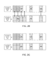
- FIG. 2B illustrates exemplary unique almost blank subframe (ABS) ratios associated access nodes in a coverage area.
- ABS almost blank subframe
- FIG. 2C illustrates an exemplary common subframe pattern associated with access nodes in a coverage area.
- FIG. 3A illustrates an exemplary method for generating a common subframe pattern in a wireless communication network.
- FIGS. 3B and 3C illustrate exemplary almost blank subframe (ABS) pattern generation tables for generating a common subframe pattern in a wireless communication network.
- ABS almost blank subframe
- FIG. 4 illustrates an exemplary processing node.
- deployment of small access nodes within a signal radius of macro access nodes (e.g., strongest signal strength) provides high data rates for wireless device users and reduces overload of the macro access nodes.
- Interference can occur at the cell edge of the small access nodes due to the reference signal strength of the macro access node in co-channel deployed communication networks.
- inter-cell interference coordination techniques for example, designating subframes as almost blank subframes (ABS), create opportunities for wireless devices at the cell edge of the small access node to receive downlink information without interference from the macro access node.
- transmissions from the macro access node inflicting high interference on the small access node users, can be periodically muted (stopped) during the designated ABS frames.
- Small access node users suffering interference from the aggressor macro access node are served during the designated ABS frames. This mitigates co-channel interference by reserving portions of wireless spectrum for the small access node users to receive downlink (DL) data from the communication network. Since transmissions from the macro access node are muted during the reserved portions of wireless spectrum radio interference from the macro access node is decreased increasing throughput to the small access node users and overall network system capacity.
- FIG. 1 illustrates an exemplary communication system 100 for generating a common subframe pattern in a wireless communication network.
- Communication system 100 can comprise a wireless devices 102 , 104 , access nodes 106 , 108 , and communication network 110 .
- Other network elements may be present in the communication system 100 to facilitate communication but are omitted for clarity, such as controller nodes, base stations, base station controllers, gateways, mobile switching centers, dispatch application processors, and location registers such as a home location register or visitor location register.
- other network elements may be present to facilitate communication between access nodes 106 , 108 and communication network 110 , which are omitted for clarity, including additional processing nodes, routers, gateways, and physical and/or wireless data links for carrying data among the various network elements.
- Wireless devices 102 , 104 can be any device configured to communicate over system 100 using a wireless communication link.
- wireless devices 102 , 104 can include a cell phone, a smart phone, a computing platform such as a laptop, palmtop, or a tablet, a personal digital assistant, or an internet access device, and combinations thereof. It is noted that while two wireless devices are illustrated in FIG. 1 as being in respective communication with each of access nodes 106 , 108 , any number of wireless devices can be implemented according to various exemplary embodiments disclosed herein.
- Wireless devices 102 , 104 can transmit and/or receive information over system 100 using various communication services. These services can include various voice, data, and/or MBMS services and applications. For example, mobile voice services, mobile data services, push-to-talk services, internet services, web browsing, email, pictures, picture messaging, video, video messaging, broadcast video, audio, voicemail, music MP3's, ring tones, stock tickers, new alerts, etc.
- Access nodes 106 , 108 can be any network node configured to provide communication between wireless devices 102 , 104 and communication networks 110 .
- Access nodes 106 , 108 can be short range access nodes or standard access nodes.
- a short range access node could include a microcell base station, a picocell base station, a femtocell base station, or the like.
- a standard access node could include a base transceiver station, a radio base station, an eNodeB device, or an enhanced eNodeB device, or the like. It is noted that while two access nodes 106 , 108 are illustrated in FIG. 1 , any number of access nodes can be implemented within system 100 .
- Communication network 110 can be a wired and/or wireless communication network, and can comprise processing nodes, routers, gateways, and physical and/or wireless data links for carrying data among various network elements, including combinations thereof, and can include a local area network, a wide area network, and an internetwork (including the Internet).
- Communication network 110 can be capable of carrying data, for example, to support voice, push-to-talk, broadcast video, and data communications by a wireless device, for example, wireless device 102 .
- Wireless network protocols can comprise code division multiple access (CDMA) 1 ⁇ RTT, Global System for Mobile communications (GSM), Universal Mobile Telecommunications System (UMTS), High-Speed Packet Access (HSPA), Evolution Data Optimized (EV-DO), EV-DO rev.
- Wired network protocols that may be utilized by communication network 110 comprise Ethernet, Fast Ethernet, Gigabit Ethernet, Local Talk (such as Carrier Sense multiple Access with Collision Avoidance), Token Ring, Fiber Distributed Data Interface (FDDI), and Asynchronous Transfer Mode (ATM).
- Communication network 110 can also comprise additional base stations, controller nodes, telephony switches, internet routers, network gateways, computer systems, communication links, or some other type of communication equipment, and combinations thereof.
- Communication links 112 , 114 , 116 , 118 , 120 can be wired or wireless and use various communication protocols such as Internet, Internet protocol (IP), local-area network (LAN), optical networking, hybrid fiber coax (HFC), telephony, T1, or some other communication format—including combinations, improvements, or variations thereof.
- Wireless communication links 112 , 114 , 116 , 118 , 120 can be a radio frequency, microwave, infrared, or other similar signal, and can use a suitable communication protocol, for example, Global System for Mobile telecommunications (GSM), Code Division Multiple Access (CDMA), Worldwide Interoperability for Microwave Access (WiMAX), or Long Term Evolution (LTE), or combinations thereof. Other wireless protocols can also be used.
- Links 112 , 114 , 116 , 118 , 120 can be a direct link or might include various equipment, intermediate components, systems, and networks.
- FIG. 2A illustrates an exemplary communication system 200 for generating a common subframe pattern in a wireless communication network.
- FIG. 2B illustrates exemplary unique almost blank subframe (ABS) ratios associated access nodes in a coverage area and
- FIG. 2C illustrates an exemplary common subframe pattern associated with access nodes in a coverage area.
- ABS almost blank subframe
- Communication system 200 can comprise wireless devices 214 , 216 , access nodes 202 , 204 , 206 , gateway node 208 , controller node 210 , and communication network 212 .
- Other network elements may be present in the communication system 200 to facilitate communication but are omitted for clarity, such as base stations, base station controllers, gateways, mobile switching centers, dispatch application processors, and location registers such as a home location register or visitor location register.
- network elements may be present to facilitate communication, such as between access nodes 202 , 204 , 206 and communication network 212 , which are omitted for clarity, including additional processing nodes, routers, gateways, and physical and/or wireless data links for carrying data among the various network elements.
- Wireless devices 214 , 216 can be any device configured to communicate over communication system 200 using a wireless interface.
- wireless devices 214 , 216 can include a remote terminal unit, a cell phone, a smart phone, a computing platform such as a laptop, palmtop, or a tablet, a personal digital assistant, or an internet access device, and combinations thereof.
- the wireless interface of wireless devices 214 , 216 can include one or more transceivers for transmitting and receiving data over communication system 200 .
- Each transceiver can be associated with the same or different frequency bands, the same or different radio access technologies, the same or different network providers, and/or the same or different services.
- wireless devices 214 , 216 can include a transceiver that is associated with one or more of the following: code division multiple access (CDMA), global system for mobile communications (GSM), worldwide interoperability for microwave access (WiMAX), long-term evolution (LTE), and/or high-speed downlink packet access (HSDPA), IEEE 802.11, wireless fidelity (Wi-Fi), Bluetooth, Zigbee, infrared data association (IrDA), multimedia broadcast multicast service (MBMS), etc.
- CDMA code division multiple access
- GSM global system for mobile communications
- WiMAX worldwide interoperability for microwave access
- LTE long-term evolution
- HSDPA high-speed downlink packet access
- IEEE 802.11 wireless fidelity
- Bluetooth Zigbee
- Zigbee Zigbee
- IrDA infrared data association
- MBMS multimedia broadcast multicast service
- wireless devices 214 , 216 can be in communication with access nodes 202 , 204 , 206 through communication links.
- the communication links can use various communication media, such as air, space, metal, optical fiber, or some other signal propagation path—including combinations thereof.
- the communication links may comprise many different signals sharing the same link.
- the communication links could include multiple signals operating in a single “air path” comprising beacon signals, user communications, communication sessions, overhead communications, frequencies, timeslots, transportation ports, logical transportation links, network sockets, packets, or communication directions.
- user communication between wireless device 214 and access node 206 could be transferred over different communication sessions, frequencies, timeslots, packets, ports, sockets, logical transport links, or in different directions—including combinations thereof.
- Wireless devices 214 , 216 can transmit and/or receive information over communication system 200 using various communication services. These services can include various voice, data, and/or MBMS services and applications. For example, mobile voice services, mobile data services, push-to-talk services, internet services web browsing, email, pictures, picture messaging, video, video messaging, broadcast video, audio, voicemail, music, MP3's, ring tones, stock tickers, new alerts, etc.
- Access nodes 202 , 204 , 206 can be any network node configured to provide communication between wireless devices 214 , 216 and communication network 212 .
- Access nodes 202 , 204 , 206 can be standard access nodes or short range, low power access nodes.
- access nodes 202 , 204 can be standard access nodes having respective coverage areas 238 , 244 .
- Access node 206 can be a short range, low power access node or small access node having a coverage area 242 .
- Access nodes 204 , 206 can each overlap at least a portion of coverage area 238 of access node 202 .
- Each access node 202 , 204 , 206 has a coverage area that includes a cell edge portion between the full strength coverage area, for example, coverage area 240 of access node 206 , and the edge of the cell coverage area 238 , 242 , 244 .
- a standard access node can be a macrocell access node such as a base transceiver station, a radio base station, an eNodeB device, or an enhanced eNodeB device, or the like.
- a short range access node can include a microcell base station, a picocell base station, a femtocell base station, or the like such as a home NodeB or a home eNodeB device.
- a wireless device configured to enter a hotspot mode can be a femtocell access node. It is noted that while three access nodes 202 , 204 , 206 are illustrated in FIG. 2 , any number of access nodes can be implemented within system 200 .
- Access nodes 202 , 204 , 206 can comprise a processor and associated circuitry to execute or direct the execution of computer-readable instructions to obtain information. Access nodes 202 , 204 , 206 can retrieve and execute software from storage, which can include a disk drive, a flash drive, memory circuitry, or some other memory device, and which can be local or remotely accessible.
- the software comprises computer programs, firmware, or some other form of machine-readable instructions, and may include an operating system, utilities, drivers, network interfaces, applications, or some other type of software, including combinations thereof.
- Access nodes 202 , 204 , 206 can receive instructions and other input at a user interface.
- Gateway node 208 can be any network node configured to interface with other network nodes using various protocols that communicates, routes, and forwards communication data addressed to a wireless devices 214 , 216 .
- gateway node 208 can act as a mobility anchor for wireless devices 214 , 216 during handovers between different frequencies and/or different radio access technologies supported by the same access node.
- Gateway node 208 can be a standalone computing device, computing system, or network component, and can be accessible, for example, by a wired or wireless connection, or through an indirect connection such as through a computer network or communication network.
- gateway node 208 can include a serving gateway (SGW) and/or public data network gateway (PGW), etc.
- SGW serving gateway
- PGW public data network gateway
- gateway node 208 is not limited to any specific technology architecture, such as Long Term Evolution (LTE) and can be used with any network architecture and/or protocol.
- LTE Long Term Evolution
- Gateway node 208 can comprise a processor and associated circuitry to execute or direct the execution of computer-readable instructions to obtain information.
- Gateway node 208 can retrieve and execute software from storage, which can include a disk drive, a flash drive, memory circuitry, or some other memory device, and which can be local or remotely accessible.
- the software comprises computer programs, firmware, or some other form of machine readable instructions, and may include an operating system, utilities, drivers, network interfaces, applications, or some other type of software, including combinations thereof.
- Gateway node 208 can receive instructions and other input at a user interface.
- Controller node 210 can be any network node configured to communicate information and/or control information over communication system 200 . Controller node 210 can be configured to transmit control information associated with a handover procedure. Controller node 210 can be a standalone computing device, computing system, or network component, and can be accessible, for example, by a wired or wireless connection, or through an indirect connection such as through a computer network or communication network.
- controller node 210 can include a mobility management entity (MME), a Home Subscriber Server (HSS), a Policy Control and Charging Rules Function (PCRF), an authentication, authorization, and accounting (AAA) node, a rights management server (RMS), a subscriber provisioning server (SPS), a policy server, etc.
- MME mobility management entity
- HSS Home Subscriber Server
- PCRF Policy Control and Charging Rules Function
- AAA authentication, authorization, and accounting
- RMS rights management server
- SPS subscriber provisioning server
- policy server etc.
- controller node 210 is not limited to any specific technology architecture,
- Controller node 210 can comprise a processor and associated circuitry to execute or direct the execution of computer-readable instructions to obtain information. Controller node 210 can retrieve and execute software from storage, which can include a disk drive, a flash drive, memory circuitry, or some other memory device, and which can be local or remotely accessible.
- the software comprises computer programs, firmware, or some other form of machine-readable instructions, and may include an operating system, utilities, drivers' network interfaces, applications, or some other type of software, including combinations thereof.
- Controller node 210 can receive instructions and other input at a user interface.
- Access node 202 can be in communication with gateway node 208 through communication link 218 and with controller node 210 through communication link 220 .
- Access node 202 can be in communication with access node 206 through communication link 222 .
- Access node 206 can be in communication with gateway node 208 through communication link 224 and with controller node 210 through communication link 226 .
- Access node 206 can be in communication with access node 204 through communication link 228 .
- Access node 204 can be in communication with access node 202 through communication link 229 , gateway node 208 through communication link 230 , and with controller node 210 through communication link 232 .
- Controller node 210 can be in communication with gateway node 208 through communication link 234 and with communication network 212 through communication link 236 .
- Communication links 218 , 220 , 222 , 224 , 226 , 228 , 229 , 230 , 232 , 234 , 236 can be wired or wireless and use various communication protocols such as Internet, Internet protocol (IP), local-area network (LAN), optical networking, hybrid fiber coax (HFC), telephony, T1, or some other communication format—including combinations, improvements, or variations thereof.
- Wireless communication links can be a radio frequency, microwave, infrared, or other similar signal, and can use a suitable communication protocol, for example, Global System for Mobile telecommunications (GSM), Code Division Multiple Access (CDMA), Worldwide Interoperability for Microwave Access (WiMAX), or Long Term Evolution (LTE), or combinations thereof.
- GSM Global System for Mobile telecommunications
- CDMA Code Division Multiple Access
- WiMAX Worldwide Interoperability for Microwave Access
- LTE Long Term Evolution
- Communication links 218 , 220 , 222 , 224 , 226 , 228 , 229 , 230 , 232 , 234 , 236 can be a direct link or might include various equipment, intermediate components, systems, and networks.
- Communication network 212 can be a wired and/or wireless communication network, and can comprise processing nodes, routers, gateways, and physical and/or wireless data links for carrying data among various network elements, including combinations thereof, an can include a local area network, a wide area network, and an internetwork (including the Internet).
- Communication network 212 can be capable of carrying data, for example, to support voice, push-to-talk, broadcast video, and data communications by a wireless device, for example, wireless device 214 .
- Wireless network protocols can comprise code division multiple access (CDMA) 1 ⁇ RTT, Global System for Mobile communications (GSM), Universal Mobile Telecommunications System (UMTS), High-Speed Packet Access (HSPA), Evolution Data Optimized (EV-DO), EV-DO rev.
- Wired network protocols that may be utilized by communication network 212 comprise Ethernet, Fast Ethernet, Gigabit Ethernet, Local Talk (such as Carrier Sense Multiple Access with Collision Avoidance), Token Ring, Fiber Distributed Data Interface (FDDI), and Asynchronous Transfer Mode (ATM).
- Communication network 212 can also comprise additional base stations, controller nodes, telephony switches, internet routers, network gateways, computer systems, communication links, or some other type of communication equipment, and combinations thereof.
- deployment of small access node 206 within a signal radius 238 of macro access node 202 (e.g., strongest signal strength) provides high data rates for wireless devices 214 , 216 and reduces overhead of macro access nodes 202 , 204 .
- Inter-cell interference coordination techniques for example, frequency-domain partitioning or designating almost blank subframes (ABS), create opportunities for wireless devices 214 , 216 at cell edge 242 of small access node 206 to receive downlink information from small access node 206 without interference from macro access nodes 202 , 204 .
- macro access nodes 202 , 204 can segment wireless spectrum to mitigate co-channel interference with small access node 206 , e.g., resource partitioning.
- Frequency-domain partitioning protects the downlink (DL) signaling of small access node 206 at cell edge 242 by using carrier aggregation (CA) techniques to exploit fragmented wireless spectrum and schedule use of data resources.
- Time-domain partitioning protects the DL signaling of small access node 206 at cell edge 242 by periodically muting (stopping) transmissions from macro access nodes 202 , 204 in designated subframes, e.g., Almost Blank Subframes (ABS), to reduce co-channel interference.
- ABS Almost Blank Subframes
- small access node 206 is provided data about the frequency-domain partitioning and set of muted ABS over, for example, X2 interfaces 222 , 228 .
- the small access node 206 can use the data to schedule wireless devices 214 , 216 located at the cell edge 242 of small access node 206 .
- neighboring macro access nodes may generate conflicting, out-of-sequence ABS patterns that comprise unique ABS ratios.
- Data about the conflicting, out-of-sequence ABS patterns may be transmitted by macro access nodes 202 , 204 to small access node 206 over, for example, separate X2 interfaces 222 , 228 .
- Interference may occur at cell edge 242 of small access node 206 due to the conflicting, out-of-sequence ABS patterns generated by macro access nodes 202 , 204 .
- FIG. 2B neighboring macro access nodes, for example, macro access node 202 , 204 .
- the DL signaling of small access node 206 at cell edge 242 may experience co-channel interference from neighboring macro access nodes 202 , 204 that each comprise data load subframes that conflict with a designated ABS of the other neighboring macro access node 202 , 204 .
- Incongruent ABS patterns of neighboring macro access nodes 202 , 204 may result in decreased throughput to wireless devices 214 , 216 operating at cell edge 242 of small access node 206 due to, for example, increased radio interference caused by access node 204 transmissions during the designated ABS of access node 202 . Consequently, generating a common ABS pattern, as illustrated in FIG. 2C , for neighboring macro access nodes 202 , 204 operating in a geographic area is desirable.
- FIG. 3A illustrates a flow chart of an exemplary method for generating a common subframe pattern in a wireless communication network.
- FIGS. 3B and 3C illustrate exemplary almost blank subframe (ABS) pattern generation tables used for generating the common subframe pattern illustrated in FIG. 3A .
- the method of FIG. 3A will be discussed with reference to the exemplary communication system 200 illustrated in FIGS. 2A-2C . However, the method can be implemented in the exemplary communication system 100 illustrated in FIG. 1 and with any suitable communication system.
- FIG. 3A depicts steps performed in a particular order for purposes of illustration and discussion, the methods discussed herein are not limited to any particular order or arrangement.
- One skilled in the art, using the disclosure provided herein, will appreciate that various steps of the methods can be omitted, rearranged, combined and/or adapted in various ways.
- a network node can synchronize a frame number associated with a plurality of access nodes.
- small access node 206 e.g., short range, low power access node
- a signal radius 238 of macro access nodes 202 , 204 e.g., strongest signal strength
- Wireless devices 214 , 216 located within a geographic coverage area of the signal radii 238 , 242 , 244 of access nodes 202 , 204 , 206 receive System Information Blocks (SIB) messages “SIBMessage” that contain a value of a System Frame Number (SFN) associated with access nodes 202 , 204 , 206 via, for example, BCH or PBCH channels.
- SIB System Information Blocks
- SFN System Frame Number
- SFN's are, for example, n bits wide and, in an exemplary embodiment, are synchronized across all access nodes 202 , 204 , 206 operating in the geographic coverage area.
- access nodes 202 , 204 , 206 operate in a synchronized mode.
- access node 206 may operate on a unique time interval, for example, 10 milliseconds, and comprise SFN's that range from 0 to 1023.
- Access node 202 may operate on a different unique time interval from access node 206 , for example, 1 millisecond, and comprise SFN's that range from 0 to 987.
- access nodes 202 and 206 Before access nodes 202 and 206 can communicate with each other, access nodes 202 , 206 must complete a timing synch (e.g., synchronize the respective timing intervals of access nodes 202 , 206 ) and set a common range for the SFN's, for example, a range from 0-1023.
- a timing synch e.g., synchronize the respective timing intervals of access nodes 202 , 206
- a common range for the SFN's for example, a range from 0-1023.
- access nodes 202 , 204 , 206 can complete a timing synch with wireless devices 214 , 216 (e.g., synchronize a respective timing interval of access nodes 202 , 204 , 206 and wireless devices 214 , 216 ) and set a common range for SFN's of access nodes 202 , 204 , 206 and subframe numbers of wireless devices 214 , 216 .
- wireless devices 214 , 216 e.g., synchronize a respective timing interval of access nodes 202 , 204 , 206 and wireless devices 214 , 216
- a unique ABS ratio associated with network nodes is determined. For example, interference can occur at cell edge 242 of small access node 206 due to the signal strength of macro access node 202 .
- time-domain partitioning protects the DL signaling of small access node 206 at cell edge 242 by periodically muting (stopping) transmissions from macro access nodes 202 in designated subframes, e.g., Almost Blank Subframes (ABS), to reduce co-channel interference.
- ABS Almost Blank Subframes
- a neighboring macro access node may generate an ABS pattern that comprises a unique ABS ratio that is out-of-sequence with the ABS pattern generated by access node 202 .
- Data about the conflicting, out-of-sequence ABS patterns are transmitted by the macro access nodes 202 , 204 to small access node 206 over, for example, X2 interfaces 222 , 228 .
- macro access nodes 202 , 204 provide data about the sets of muted ABS to small access node 206 in a load information messages “ABSInformation” over, for example, X2 interfaces 222 , 228 .
- the ABSInformation messages contain ABS pattern information “ABSPatternInfo” that indicate subframes designated by macro access nodes 202 , 204 as ABS for the purpose of interference coordination.
- ABS are measured in bit maps and are approximately n bits wide. Each position in the bitmap represents an ABS or non-ABS DL subframe. For example, a position value “1” in the bitmap may indicate an ABS. A position value “0” in the bitmap may indicate a non-ABS.
- the first position of the ABS pattern may correspond, for example, to subframe “0” in a radio frame where the SFN equals zero.
- ABS ratios of macro access nodes 202 , 204 are unique, the ABS patterns generated by macro access nodes 202 , 204 may not be congruent. Incongruent ABS patterns of neighboring macro access nodes 202 , 204 may result in decreased throughput to wireless devices 214 , 216 operating at cell edge 242 of small access node 206 due to, for example, increased radio interference caused by macro access node 204 transmissions during the designated ABS of macro access node 202 .
- a unique ABS ratio associated with each macro access node 202 , 204 may be determined, for example, from vendor specific algorithms.
- a common ABS pattern for macro access nodes 202 , 204 may be generated based on the unique ABS ratios for macro access nodes 202 , 204 located in the geographic coverage area.
- each macro access nodes 202 , 204 located in the geographic coverage area may comprise an ABS pattern generator.
- the ABS pattern generator can be, for example, gateway node 208 , controller node 210 , or processor node 400 illustrated in FIG. 4 , and may be, for example, embedded in access nodes 202 , 204 , 206 , adjacent to access nodes 202 , 204 , 206 , or an element of communication network 212 .
- the ABS pattern generator (not shown) may be configured to generate an ABS pattern based on the determined unique ABS ratios of each macro access node 202 , 204 located in the geographic coverage area.
- the maximum number of ABS based on a bitmap of 0-39 is 40 subframes and can be designated as a percentage, for example, 12.5%
- the enabling bit sequence for a subframe configuration based on the generated ABS table can be, for example, 1, 5, 11, 21, 31.
- the maximum bitmap ABS e.g., 40
- the ABS pattern may repeat every 40 milliseconds (ms) from SFN “0”.
- the amount of ABS can be determined by the macro access node 202 , 204 using its own algorithm.
- the maximum number of ABS based on bitmap is 20 subframes.
- the maximum bitmap ABS e.g., 20
- the ABS pattern may repeat every 20 ms from SFN “0”.
- the amount of ABS can be determined by the macro access node 202 , 204 using its own algorithm. Special subframes may be excluded from the ABS bitmap consideration.
- illustrated in FIG. 3C illustrated in FIG.
- the maximum number of ABS based on a bitmap of 0-19 is 20 subframes and can be designated as a percentage, for example, 12.5%, and the enabling bit sequence for a subframe configuration based on the generated ABS table can be, for example, 4.
- the common ABS pattern generated based on the determined ABS ratios of each macro access node 202 , 204 , may be provided to every macro access node 202 , 204 located in the geographic area to minimize inter-cell interference from neighboring macro access nodes 202 , 204 . For example, factors such as jitter, delay, and latency may be used to generate the unique ABS ratios at access nodes 202 , 204 and the ABS generator considers the unique ABS ratios when generating the common ABS pattern.
- the common ABS pattern provides sufficient ABS to accommodate the unique ABS ratios of the macro access node 202 , 204 with the highest percentage of ABS in the non-congruent ABS pattern.
- the common subframe pattern is provided to the small access node.
- time-domain partitioning protects the DL signaling of small access node 206 at cell edge 242 by periodically muting (stopping) transmissions from macro access nodes 202 , 204 in designated subframes, e.g., ABS′, to reduce co-channel interference.
- small access node 206 is provided data about the common ABS pattern over, for example, X2 interfaces 222 , 228 associated with macro access nodes 202 , 204 .
- the small access node 206 can use the data to schedule wireless devices 214 , 216 located at the cell edge 242 of small access node 206 without interference from macro access nodes 202 , 204 .
- Time-domain partitioning protects the DL signaling of small access node 206 at cell edge 242 by periodically muting (stopping) transmissions from macro access nodes 202 , 204 in designated subframes, e.g., Almost Blank Subframes (ABS), to reduce co-channel interference.
- small access node 206 is provided data about the frequency-domain partitioning and set of muted ABS over, for example, X2 interfaces 222 , 228 .
- the small access node 206 can use the data to schedule wireless devices 214 , 216 located at the cell edge 242 of small access node 206 .
- FIG. 4 illustrates an exemplary processing node 400 in a communication system.
- Processing node 400 comprises communication interface 402 , user interface 404 , and processing system 406 in communication with communication interface 402 and user interface 404 .
- Processing node 400 can be configured to determine a communication access node for a wireless device.
- Processing system 406 includes storage 408 , which can comprise a disk drive, flash drive, memory circuitry, or other memory device.
- Storage 408 can store software 410 which is used in the operation of the processing node 400 .
- Storage 408 may include a disk drive, flash drive, data storage circuitry, or some other memory apparatus.
- Software 410 may include computer programs, firmware, or some other form of machine-readable instructions, including an operating system, utilities, drivers, network interfaces, applications, or some other type of software.
- Processing system 406 may include a microprocessor and other circuitry to retrieve and execute software 410 from storage 408 .
- Processing node 400 may further include other components such as a power management unit, a control interface unit, etc., which are omitted for clarity.
- Communication interface 402 permits processing node 400 to communicate with other network elements.
- User interface 404 permits the configuration and control of the operation of processing node 400 .
- processing node 400 examples include access nodes 106 , 108 , 202 , 204 , 206 , gateway node 208 , and controller nodes 210 .
- Processing node 400 can also be an adjunct or component of a network element, such as an element of access nodes 106 , 108 , 202 , 204 , 206 , gateway node 208 , and controller node 210 .
- Processing node 400 can also be another network element in a communication system. Further, the functionality of processing node 400 can be distributed over two or more network elements of a communication system.
- the exemplary systems and methods described herein can be performed under the control of a processing system executing computer-readable codes embodied on a computer-readable recording medium or communication signals transmitted through a transitory medium.
- the computer-readable recording medium is any data storage device that can store data readable by a processing system, and includes both volatile and nonvolatile media, removable and non-removable media, and contemplates media readable by a database, a computer, and various other network devices.
- Examples of the computer-readable recording medium include, but are not limited to, read-only memory (ROM), random-access memory (RAM), erasable electrically programmable ROM (EEPROM), flash memory or other memory technology, holographic media or other optical disc storage, magnetic storage including magnetic tape and magnetic disk, and solid state storage devices.
- the computer-readable recording medium can also be distributed over network-coupled computer systems so that the computer-readable code is stored and executed in a distributed fashion.
- the communication signals transmitted through a transitory medium may include, for example, modulated signals transmitted through wired or wireless transmission paths.
Abstract
Description
Claims (12)
Priority Applications (1)
| Application Number | Priority Date | Filing Date | Title |
|---|---|---|---|
| US14/611,312 US9692581B1 (en) | 2015-02-02 | 2015-02-02 | Systems and methods for load and interference coordination in a wireless communication network |
Applications Claiming Priority (1)
| Application Number | Priority Date | Filing Date | Title |
|---|---|---|---|
| US14/611,312 US9692581B1 (en) | 2015-02-02 | 2015-02-02 | Systems and methods for load and interference coordination in a wireless communication network |
Publications (1)
| Publication Number | Publication Date |
|---|---|
| US9692581B1 true US9692581B1 (en) | 2017-06-27 |
Family
ID=59070297
Family Applications (1)
| Application Number | Title | Priority Date | Filing Date |
|---|---|---|---|
| US14/611,312 Active 2035-07-24 US9692581B1 (en) | 2015-02-02 | 2015-02-02 | Systems and methods for load and interference coordination in a wireless communication network |
Country Status (1)
| Country | Link |
|---|---|
| US (1) | US9692581B1 (en) |
Cited By (2)
| Publication number | Priority date | Publication date | Assignee | Title |
|---|---|---|---|---|
| US20210345350A1 (en) * | 2020-04-30 | 2021-11-04 | Huawei Technologies Co., Ltd. | Multi-Radio Frequency Anti-Interference Method and Related Device |
| US20220231803A1 (en) * | 2019-06-05 | 2022-07-21 | Sony Group Corporation | Communication device and method |
Citations (12)
| Publication number | Priority date | Publication date | Assignee | Title |
|---|---|---|---|---|
| US20110310830A1 (en) * | 2010-06-18 | 2011-12-22 | Mediatek Inc. | Method for Coordinating Transmissions Between Different Communications Apparatuses and Communication Sapparatuses Utilizing the Same |
| US20130044600A1 (en) * | 2011-08-18 | 2013-02-21 | Alcatel-Lucent Deutschland | Method and apparatus for providing increased small cell resource utilization |
| US20130107798A1 (en) * | 2011-11-02 | 2013-05-02 | Hitachi, Ltd. | ABS-based Method for Inter Cell Interference Coordination in LTE-Advanced Networks |
| US20130107826A1 (en) * | 2011-10-29 | 2013-05-02 | Esmael Hejazi Dinan | Special Subframe Allocation |
| US8743723B2 (en) | 2010-11-05 | 2014-06-03 | Interdigital Patent Holdings, Inc. | Methods, apparatus and systems for applying almost blank subframe (ABS) patterns |
| US20140162662A1 (en) * | 2011-05-27 | 2014-06-12 | Ntt Docomo, Inc. | Communication control device and communication control method |
| US20140269457A1 (en) | 2011-10-27 | 2014-09-18 | Telefonaktiebolaget L M Ericsson (Publ) | Method and Apparatus for Handling the TDD Tail Problem for an ABS Pattern |
| US20140321434A1 (en) * | 2013-04-24 | 2014-10-30 | Alcatel-Lucent Usa Inc. | Method and apparatus for determination of almost blank subframe pattern by network listening |
| US20150029988A1 (en) * | 2012-03-16 | 2015-01-29 | Huawei Technologies Co., Ltd. | Method, device and system for uplink resource allocation |
| US20150029907A1 (en) * | 2013-07-23 | 2015-01-29 | Telefonica, S.A. | Method to optimize almost blank subframe usage in a wireless network |
| US20150119053A1 (en) * | 2012-05-09 | 2015-04-30 | Ntt Docomo, Inc. | Radio communication system and radio base station |
| US20160021621A1 (en) * | 2012-03-13 | 2016-01-21 | Zte (Usa) Inc. | Interference management in the heterogeneous network |
-
2015
- 2015-02-02 US US14/611,312 patent/US9692581B1/en active Active
Patent Citations (12)
| Publication number | Priority date | Publication date | Assignee | Title |
|---|---|---|---|---|
| US20110310830A1 (en) * | 2010-06-18 | 2011-12-22 | Mediatek Inc. | Method for Coordinating Transmissions Between Different Communications Apparatuses and Communication Sapparatuses Utilizing the Same |
| US8743723B2 (en) | 2010-11-05 | 2014-06-03 | Interdigital Patent Holdings, Inc. | Methods, apparatus and systems for applying almost blank subframe (ABS) patterns |
| US20140162662A1 (en) * | 2011-05-27 | 2014-06-12 | Ntt Docomo, Inc. | Communication control device and communication control method |
| US20130044600A1 (en) * | 2011-08-18 | 2013-02-21 | Alcatel-Lucent Deutschland | Method and apparatus for providing increased small cell resource utilization |
| US20140269457A1 (en) | 2011-10-27 | 2014-09-18 | Telefonaktiebolaget L M Ericsson (Publ) | Method and Apparatus for Handling the TDD Tail Problem for an ABS Pattern |
| US20130107826A1 (en) * | 2011-10-29 | 2013-05-02 | Esmael Hejazi Dinan | Special Subframe Allocation |
| US20130107798A1 (en) * | 2011-11-02 | 2013-05-02 | Hitachi, Ltd. | ABS-based Method for Inter Cell Interference Coordination in LTE-Advanced Networks |
| US20160021621A1 (en) * | 2012-03-13 | 2016-01-21 | Zte (Usa) Inc. | Interference management in the heterogeneous network |
| US20150029988A1 (en) * | 2012-03-16 | 2015-01-29 | Huawei Technologies Co., Ltd. | Method, device and system for uplink resource allocation |
| US20150119053A1 (en) * | 2012-05-09 | 2015-04-30 | Ntt Docomo, Inc. | Radio communication system and radio base station |
| US20140321434A1 (en) * | 2013-04-24 | 2014-10-30 | Alcatel-Lucent Usa Inc. | Method and apparatus for determination of almost blank subframe pattern by network listening |
| US20150029907A1 (en) * | 2013-07-23 | 2015-01-29 | Telefonica, S.A. | Method to optimize almost blank subframe usage in a wireless network |
Cited By (4)
| Publication number | Priority date | Publication date | Assignee | Title |
|---|---|---|---|---|
| US20220231803A1 (en) * | 2019-06-05 | 2022-07-21 | Sony Group Corporation | Communication device and method |
| US11979344B2 (en) * | 2019-06-05 | 2024-05-07 | Sony Group Corporation | Communication device and method |
| US20210345350A1 (en) * | 2020-04-30 | 2021-11-04 | Huawei Technologies Co., Ltd. | Multi-Radio Frequency Anti-Interference Method and Related Device |
| US11737127B2 (en) * | 2020-04-30 | 2023-08-22 | Huawei Technologies Co., Ltd. | Multi-radio frequency anti-interference method and related device |
Similar Documents
| Publication | Publication Date | Title |
|---|---|---|
| US8842629B2 (en) | Scheduling method, device and system based on quality of service | |
| US8768373B2 (en) | Adaptive flexible bandwidth wireless systems | |
| US9001758B2 (en) | Flexible bandwidth small cells | |
| US9247554B2 (en) | Network control to direct user devices in mutual machine-to-machine communications into unlicensed frequency bands to decrease interference | |
| US9338769B1 (en) | Method of scheduling communication in a wireless communication network | |
| KR20170127443A (en) | Resource partitioning between wireless backhaul and access communications in millimeter wave networks | |
| KR20160145032A (en) | Techniques for transmitting data over an unlicensed radio frequency spectrum band in accordance with an agreement between operators | |
| US10178664B1 (en) | Interference mitigation in heterogeneous networks | |
| US11785589B2 (en) | Carrier aggregation with narrow bandwidth carriers | |
| US11722905B1 (en) | Dedicating antenna elements to specific wireless devices | |
| US9560668B1 (en) | Systems and methods for scheduling low-delay transmissions in a communication network | |
| US9692581B1 (en) | Systems and methods for load and interference coordination in a wireless communication network | |
| US9681349B1 (en) | Method and system for managing traffic offload in a wireless communication network based on closed access mode conditions | |
| US9241289B1 (en) | Dynamic adjustment of cell reselection parameters for a wireless communication device | |
| US9344857B1 (en) | Frequency band allocation in a wireless communication network | |
| US10555315B1 (en) | Interference mitigation in heterogeneous networks | |
| US9832773B1 (en) | Method of scheduling communication in a wireless communication network | |
| US10292137B1 (en) | Reducing latency in an unlicensed frequency spectrum | |
| US10356801B1 (en) | Systems and methods for improving spectral efficiencies in a wireless communication network | |
| Garcia-Villegas et al. | SENSEFUL: An SDN-based joint access and backhaul coordination for Dense Wi-Fi Small Cells | |
| US9439203B1 (en) | Method of scheduling communication in a wireless communication network | |
| US10798710B1 (en) | Selection of primary carrier based on usage type | |
| US9462601B1 (en) | Method of scheduling communication in a wireless communication network | |
| US10356776B1 (en) | Dynamic deployment of new frame configuration | |
| US9265060B1 (en) | Method of scheduling communication in a wireless communication network |
Legal Events
| Date | Code | Title | Description |
|---|---|---|---|
| AS | Assignment |
Owner name: SPRINT SPECTRUM LP, KANSAS Free format text: ASSIGNMENT OF ASSIGNORS INTEREST;ASSIGNORS:KIM, YUN SUNG;SUNG, SANGHOON;TAILOR, PINAL;AND OTHERS;REEL/FRAME:034862/0739 Effective date: 20150130 |
|
| AS | Assignment |
Owner name: DEUTSCHE BANK TRUST COMPANY AMERICAS, NEW YORK Free format text: GRANT OF FIRST PRIORITY AND JUNIOR PRIORITY SECURITY INTEREST IN PATENT RIGHTS;ASSIGNOR:SPRINT SPECTRUM L.P.;REEL/FRAME:041937/0632 Effective date: 20170203 |
|
| STCF | Information on status: patent grant |
Free format text: PATENTED CASE |
|
| AS | Assignment |
Owner name: DEUTSCHE BANK TRUST COMPANY AMERICAS, NEW YORK Free format text: SECURITY AGREEMENT;ASSIGNORS:T-MOBILE USA, INC.;ISBV LLC;T-MOBILE CENTRAL LLC;AND OTHERS;REEL/FRAME:053182/0001 Effective date: 20200401 |
|
| AS | Assignment |
Owner name: SPRINT SPECTRUM L.P., KANSAS Free format text: TERMINATION AND RELEASE OF FIRST PRIORITY AND JUNIOR PRIORITY SECURITY INTEREST IN PATENT RIGHTS;ASSIGNOR:DEUTSCHE BANK TRUST COMPANY AMERICAS;REEL/FRAME:052313/0299 Effective date: 20200401 |
|
| MAFP | Maintenance fee payment |
Free format text: PAYMENT OF MAINTENANCE FEE, 4TH YEAR, LARGE ENTITY (ORIGINAL EVENT CODE: M1551); ENTITY STATUS OF PATENT OWNER: LARGE ENTITY Year of fee payment: 4 |
|
| AS | Assignment |
Owner name: SPRINT SPECTRUM LLC, WASHINGTON Free format text: CHANGE OF NAME;ASSIGNOR:SPRINT SPECTRUM L.P.;REEL/FRAME:059044/0022 Effective date: 20210325 |
|
| AS | Assignment |
Owner name: SPRINT SPECTRUM LLC, KANSAS Free format text: RELEASE BY SECURED PARTY;ASSIGNOR:DEUTSCHE BANK TRUST COMPANY AMERICAS;REEL/FRAME:062595/0001 Effective date: 20220822 Owner name: SPRINT INTERNATIONAL INCORPORATED, KANSAS Free format text: RELEASE BY SECURED PARTY;ASSIGNOR:DEUTSCHE BANK TRUST COMPANY AMERICAS;REEL/FRAME:062595/0001 Effective date: 20220822 Owner name: SPRINT COMMUNICATIONS COMPANY L.P., KANSAS Free format text: RELEASE BY SECURED PARTY;ASSIGNOR:DEUTSCHE BANK TRUST COMPANY AMERICAS;REEL/FRAME:062595/0001 Effective date: 20220822 Owner name: SPRINTCOM LLC, KANSAS Free format text: RELEASE BY SECURED PARTY;ASSIGNOR:DEUTSCHE BANK TRUST COMPANY AMERICAS;REEL/FRAME:062595/0001 Effective date: 20220822 Owner name: CLEARWIRE IP HOLDINGS LLC, KANSAS Free format text: RELEASE BY SECURED PARTY;ASSIGNOR:DEUTSCHE BANK TRUST COMPANY AMERICAS;REEL/FRAME:062595/0001 Effective date: 20220822 Owner name: CLEARWIRE COMMUNICATIONS LLC, KANSAS Free format text: RELEASE BY SECURED PARTY;ASSIGNOR:DEUTSCHE BANK TRUST COMPANY AMERICAS;REEL/FRAME:062595/0001 Effective date: 20220822 Owner name: BOOST WORLDWIDE, LLC, KANSAS Free format text: RELEASE BY SECURED PARTY;ASSIGNOR:DEUTSCHE BANK TRUST COMPANY AMERICAS;REEL/FRAME:062595/0001 Effective date: 20220822 Owner name: ASSURANCE WIRELESS USA, L.P., KANSAS Free format text: RELEASE BY SECURED PARTY;ASSIGNOR:DEUTSCHE BANK TRUST COMPANY AMERICAS;REEL/FRAME:062595/0001 Effective date: 20220822 Owner name: T-MOBILE USA, INC., WASHINGTON Free format text: RELEASE BY SECURED PARTY;ASSIGNOR:DEUTSCHE BANK TRUST COMPANY AMERICAS;REEL/FRAME:062595/0001 Effective date: 20220822 Owner name: T-MOBILE CENTRAL LLC, WASHINGTON Free format text: RELEASE BY SECURED PARTY;ASSIGNOR:DEUTSCHE BANK TRUST COMPANY AMERICAS;REEL/FRAME:062595/0001 Effective date: 20220822 Owner name: PUSHSPRING, LLC, WASHINGTON Free format text: RELEASE BY SECURED PARTY;ASSIGNOR:DEUTSCHE BANK TRUST COMPANY AMERICAS;REEL/FRAME:062595/0001 Effective date: 20220822 Owner name: LAYER3 TV, LLC, WASHINGTON Free format text: RELEASE BY SECURED PARTY;ASSIGNOR:DEUTSCHE BANK TRUST COMPANY AMERICAS;REEL/FRAME:062595/0001 Effective date: 20220822 Owner name: IBSV LLC, WASHINGTON Free format text: RELEASE BY SECURED PARTY;ASSIGNOR:DEUTSCHE BANK TRUST COMPANY AMERICAS;REEL/FRAME:062595/0001 Effective date: 20220822 |