US9677702B2 - Case having standing leg for electronic devices - Google Patents
Case having standing leg for electronic devices Download PDFInfo
- Publication number
- US9677702B2 US9677702B2 US14/626,670 US201514626670A US9677702B2 US 9677702 B2 US9677702 B2 US 9677702B2 US 201514626670 A US201514626670 A US 201514626670A US 9677702 B2 US9677702 B2 US 9677702B2
- Authority
- US
- United States
- Prior art keywords
- standing leg
- case
- pivoting
- protective frame
- leg
- Prior art date
- Legal status (The legal status is an assumption and is not a legal conclusion. Google has not performed a legal analysis and makes no representation as to the accuracy of the status listed.)
- Active
Links
- 230000001681 protective effect Effects 0.000 claims abstract description 88
- 230000013011 mating Effects 0.000 claims description 24
- 210000004905 finger nail Anatomy 0.000 claims description 7
- 239000000463 material Substances 0.000 claims description 6
- 238000003780 insertion Methods 0.000 claims description 5
- 230000037431 insertion Effects 0.000 claims description 5
- 239000007779 soft material Substances 0.000 claims description 5
- 239000004433 Thermoplastic polyurethane Substances 0.000 claims description 3
- 239000004417 polycarbonate Substances 0.000 claims description 3
- 229920000515 polycarbonate Polymers 0.000 claims description 3
- 229920002803 thermoplastic polyurethane Polymers 0.000 claims description 3
- OKTJSMMVPCPJKN-UHFFFAOYSA-N Carbon Chemical compound [C] OKTJSMMVPCPJKN-UHFFFAOYSA-N 0.000 claims description 2
- RTAQQCXQSZGOHL-UHFFFAOYSA-N Titanium Chemical compound [Ti] RTAQQCXQSZGOHL-UHFFFAOYSA-N 0.000 claims description 2
- 229910052782 aluminium Inorganic materials 0.000 claims description 2
- XAGFODPZIPBFFR-UHFFFAOYSA-N aluminium Chemical compound [Al] XAGFODPZIPBFFR-UHFFFAOYSA-N 0.000 claims description 2
- 239000002131 composite material Substances 0.000 claims description 2
- 229910002804 graphite Inorganic materials 0.000 claims description 2
- 239000010439 graphite Substances 0.000 claims description 2
- 239000002184 metal Substances 0.000 claims description 2
- 229910052751 metal Inorganic materials 0.000 claims description 2
- 239000004033 plastic Substances 0.000 claims description 2
- 229920003023 plastic Polymers 0.000 claims description 2
- 239000004800 polyvinyl chloride Substances 0.000 claims description 2
- 239000010936 titanium Substances 0.000 claims description 2
- 229910052719 titanium Inorganic materials 0.000 claims description 2
- 238000010276 construction Methods 0.000 description 2
- -1 for example Substances 0.000 description 2
- 239000013013 elastic material Substances 0.000 description 1
- 238000000034 method Methods 0.000 description 1
- 239000000203 mixture Substances 0.000 description 1
- 238000000465 moulding Methods 0.000 description 1
- 239000012858 resilient material Substances 0.000 description 1
- 229920002725 thermoplastic elastomer Polymers 0.000 description 1
Images


Classifications
-
- H—ELECTRICITY
- H04—ELECTRIC COMMUNICATION TECHNIQUE
- H04B—TRANSMISSION
- H04B1/00—Details of transmission systems, not covered by a single one of groups H04B3/00 - H04B13/00; Details of transmission systems not characterised by the medium used for transmission
- H04B1/38—Transceivers, i.e. devices in which transmitter and receiver form a structural unit and in which at least one part is used for functions of transmitting and receiving
- H04B1/3827—Portable transceivers
- H04B1/3888—Arrangements for carrying or protecting transceivers
-
- F—MECHANICAL ENGINEERING; LIGHTING; HEATING; WEAPONS; BLASTING
- F16—ENGINEERING ELEMENTS AND UNITS; GENERAL MEASURES FOR PRODUCING AND MAINTAINING EFFECTIVE FUNCTIONING OF MACHINES OR INSTALLATIONS; THERMAL INSULATION IN GENERAL
- F16M—FRAMES, CASINGS OR BEDS OF ENGINES, MACHINES OR APPARATUS, NOT SPECIFIC TO ENGINES, MACHINES OR APPARATUS PROVIDED FOR ELSEWHERE; STANDS; SUPPORTS
- F16M11/00—Stands or trestles as supports for apparatus or articles placed thereon ; Stands for scientific apparatus such as gravitational force meters
-
- A—HUMAN NECESSITIES
- A45—HAND OR TRAVELLING ARTICLES
- A45C—PURSES; LUGGAGE; HAND CARRIED BAGS
- A45C11/00—Receptacles for purposes not provided for in groups A45C1/00-A45C9/00
-
- F—MECHANICAL ENGINEERING; LIGHTING; HEATING; WEAPONS; BLASTING
- F16—ENGINEERING ELEMENTS AND UNITS; GENERAL MEASURES FOR PRODUCING AND MAINTAINING EFFECTIVE FUNCTIONING OF MACHINES OR INSTALLATIONS; THERMAL INSULATION IN GENERAL
- F16M—FRAMES, CASINGS OR BEDS OF ENGINES, MACHINES OR APPARATUS, NOT SPECIFIC TO ENGINES, MACHINES OR APPARATUS PROVIDED FOR ELSEWHERE; STANDS; SUPPORTS
- F16M11/00—Stands or trestles as supports for apparatus or articles placed thereon ; Stands for scientific apparatus such as gravitational force meters
- F16M11/02—Heads
- F16M11/04—Means for attachment of apparatus; Means allowing adjustment of the apparatus relatively to the stand
- F16M11/041—Allowing quick release of the apparatus
-
- F—MECHANICAL ENGINEERING; LIGHTING; HEATING; WEAPONS; BLASTING
- F16—ENGINEERING ELEMENTS AND UNITS; GENERAL MEASURES FOR PRODUCING AND MAINTAINING EFFECTIVE FUNCTIONING OF MACHINES OR INSTALLATIONS; THERMAL INSULATION IN GENERAL
- F16M—FRAMES, CASINGS OR BEDS OF ENGINES, MACHINES OR APPARATUS, NOT SPECIFIC TO ENGINES, MACHINES OR APPARATUS PROVIDED FOR ELSEWHERE; STANDS; SUPPORTS
- F16M11/00—Stands or trestles as supports for apparatus or articles placed thereon ; Stands for scientific apparatus such as gravitational force meters
- F16M11/02—Heads
- F16M11/04—Means for attachment of apparatus; Means allowing adjustment of the apparatus relatively to the stand
- F16M11/06—Means for attachment of apparatus; Means allowing adjustment of the apparatus relatively to the stand allowing pivoting
- F16M11/10—Means for attachment of apparatus; Means allowing adjustment of the apparatus relatively to the stand allowing pivoting around a horizontal axis
- F16M11/105—Means for attachment of apparatus; Means allowing adjustment of the apparatus relatively to the stand allowing pivoting around a horizontal axis the horizontal axis being the roll axis, e.g. for creating a landscape-portrait rotation
-
- F—MECHANICAL ENGINEERING; LIGHTING; HEATING; WEAPONS; BLASTING
- F16—ENGINEERING ELEMENTS AND UNITS; GENERAL MEASURES FOR PRODUCING AND MAINTAINING EFFECTIVE FUNCTIONING OF MACHINES OR INSTALLATIONS; THERMAL INSULATION IN GENERAL
- F16M—FRAMES, CASINGS OR BEDS OF ENGINES, MACHINES OR APPARATUS, NOT SPECIFIC TO ENGINES, MACHINES OR APPARATUS PROVIDED FOR ELSEWHERE; STANDS; SUPPORTS
- F16M13/00—Other supports for positioning apparatus or articles; Means for steadying hand-held apparatus or articles
- F16M13/02—Other supports for positioning apparatus or articles; Means for steadying hand-held apparatus or articles for supporting on, or attaching to, an object, e.g. tree, gate, window-frame, cycle
- F16M13/022—Other supports for positioning apparatus or articles; Means for steadying hand-held apparatus or articles for supporting on, or attaching to, an object, e.g. tree, gate, window-frame, cycle repositionable
-
- H—ELECTRICITY
- H04—ELECTRIC COMMUNICATION TECHNIQUE
- H04B—TRANSMISSION
- H04B1/00—Details of transmission systems, not covered by a single one of groups H04B3/00 - H04B13/00; Details of transmission systems not characterised by the medium used for transmission
- H04B1/38—Transceivers, i.e. devices in which transmitter and receiver form a structural unit and in which at least one part is used for functions of transmitting and receiving
- H04B1/3827—Portable transceivers
- H04B1/3877—Arrangements for enabling portable transceivers to be used in a fixed position, e.g. cradles or boosters
-
- A—HUMAN NECESSITIES
- A45—HAND OR TRAVELLING ARTICLES
- A45C—PURSES; LUGGAGE; HAND CARRIED BAGS
- A45C11/00—Receptacles for purposes not provided for in groups A45C1/00-A45C9/00
- A45C2011/002—Receptacles for purposes not provided for in groups A45C1/00-A45C9/00 for portable handheld communication devices, e.g. mobile phone, pager, beeper, PDA, smart phone
-
- A—HUMAN NECESSITIES
- A45—HAND OR TRAVELLING ARTICLES
- A45C—PURSES; LUGGAGE; HAND CARRIED BAGS
- A45C11/00—Receptacles for purposes not provided for in groups A45C1/00-A45C9/00
- A45C2011/003—Receptacles for purposes not provided for in groups A45C1/00-A45C9/00 for portable computing devices, e.g. laptop, tablet, netbook, game boy, navigation system, calculator
-
- A—HUMAN NECESSITIES
- A45—HAND OR TRAVELLING ARTICLES
- A45C—PURSES; LUGGAGE; HAND CARRIED BAGS
- A45C2200/00—Details not otherwise provided for in A45C
- A45C2200/15—Articles convertible into a stand, e.g. for displaying purposes
Definitions
- the present invention relates to a case having a standing log for an electronic device and, more particularly, to a smart phone case having a standing leg for propping up the smart phone case.
- the standing leg is pivoted with both of the soft protective case and the hard protective frame of the case.
- Mobile electronic devices such as mobile phones, smart phones, tablet, computers and the like are in wide use around the world. A user grips such device in his hand or hands to use it and uses his fingers to use various applications of the device. However, while using the device, the user may accidentally drop the device thereby causing damage to the device. In addition, use of mobile electronic devices may cause hand, limb and back problems due to the physical stress of holding the electronic device for an extended period of time.
- the present invention contrives to solve the disadvantages of the prior art.
- the present invention provides a case having a standing leg for an electronic device such as a mobile phone, smart phone, tablet computer and the like, and, more particularly, to a standing leg pivoted not just with the hard protective frame of the case but also with the soft protective case of the case.
- the object of the present invention is to provide a case having a standing leg for an electronic device, including a soft protective cover, a hard protective frame, and a standing leg.
- An opening is formed on a back portion of the hard protective frame to receive the standing leg therein.
- the standing leg is pivoted with the soft protective cover and the hard protective frame.
- the standing leg is configured to rotate up to about a predetermined angle until the rotation of the standing leg is prevented by a pivoting end wall of the hard protective frame.
- Another object of the present invention is to provide a case having a standing leg for an electronic device such that the opening is sized to receive the standing leg.
- the standing leg is rotatable from a closed position in which it is received in the opening to an open position in which the standing leg is rotated about the predetermined angle. In an open position, the electronic device may rest on a surface at a preferred viewing angle.
- the case of the present invention has a simple, stylish structure of a standing leg for propping up the case; (2) the standing leg is easy-to-use and convenient; (3) the standing leg is more durable and less vulnerable to scratches or damages because the standing leg is pivoted not just with the hard protective frame of the case but also with the soft protective case of the case; (4) once a mobile phone is received and secured in the case, the standing leg is very securely pivoted and the opening and closing of the standing leg is very convenient; (5) the soft protective cover, hard protective frame and standing leg are very easy to assemble and the standing leg is easy to be replaced; (6) the surface of the standing leg is flush with the surface of the hard protective frame and the appearance and finish are stylish; and (7) the standing leg can be open conveniently by using a fingernail and the operation is easy.
- FIG. 1 shows a perspective view of a case having a standing leg according to one embodiment of the present invention
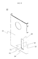
- FIG. 2 shows a perspective view of the case with the standing leg in an open position according to the present invention
- FIG. 3 shows another perspective view of the case with the standing leg open to prop up the case and an electronic device therein in a landscape orientation;
- FIG. 4 shows an exploded view of the case having a soft protective cover, a hard protective, frame and a standing leg according to the present invention
- FIG. 5 shows a perspective view of the soft protective cover
- FIG. 6 shows a perspective view of the standing leg
- FIG. 7 shows another perspective view of the standing leg
- FIG. 8 shows a perspective view of the hard protective frame
- FIG. 9 shows another perspective view of the hard protective frame
- FIG. 10 shows a partial perspective view of the hard protective frame showing the opening of the hard protective frame
- FIG. 11 shows a perspective view of the case with a standing leg open to prop up the case according to another embodiment of the present invention.
- FIG. 12 shows another perspective view of the case with a standing leg open to prop up the case according to another embodiment of the present invention.
- FIG. 1 shows a perspective view of a case 10 having a standing leg 40 and FIG. 2 shows the ease 10 when the standing leg 40 is in an open position.
- FIG. 3 shows the case 10 when the standing leg 40 is in an open position to prop up the case 10 and an electronic device 100 (not shown) therein in a landscape orientation.
- FIG. 4 shows an exploded view of the case 10 having a soft, protective cover 20 , a hard protective frame 30 and a standing leg 40 according to one embodiment of the present invention.
- the electronic device may be a mobile phone, smart phone, tablet computer, MP3 player, Personal Digital Assistant or the like.
- the case 10 of the present invention having a standing leg 40 for an electronic device 100 , comprises a soft protective cover 20 , a hard protective frame 30 , and a standing leg 40 .
- the sort protective cover 20 protects the electronic device 100 installed, therein and covers a back portion 110 of the electronic device 100 .
- the hard protective frame 30 is configured to removably mount over the soft, protective cover 20 and the standing leg 40 props up the electronic device.
- An opening 40 is formed on a back portion 31 of the hard protective frame 30 and the standing leg 40 fits in the opening 50 .
- the standing leg 40 is configured to rotate up to about a predetermined angle 80 .
- the soft protective cover 20 substantially covers the entire electronic device 100 (not shown) except for the screen side or front portion and providing cutout portions to allow for access to certain portions of the electronic device such as a camera lens, various ports, switches, and the like.
- the case 10 props up the electronic device 100 on a flat surface at a preferred viewing angle.
- the opening 50 is sized to receive the standing leg 40
- the standing leg 40 is rotatable from, a closed position in which it is received in the opening 40 to an open position in which the standing leg 40 is rotated about the predetermined angle 80 so that the electronic device 100 may rest on a surface at a preferred viewing angle.
- the standing leg 40 is pivoted with the soft protective cover 20 or the hard protective frame 30 .
- the standing leg 40 is pivoted with both of the soft protective cover 20 and the hard protective frame 30 .
- the standing leg 40 may be pivoted either with the soft protective cover 20 or with the hard protective frame 30 .
- FIG. 5 shows a perspective view of the soft protective cover 20 and FIGS. 6 and 7 show perspective views of the standing leg 40 .
- FIGS. 8 and 9 show perspective views of the hard protective frame 30 .
- the standing leg 40 includes a pivoting end 43 and the soft protective cover 20 includes a pivoting groove 25 formed on a back portion 21 of the soft protective cover 20 .
- the pivoting end 43 comprises projections 45 formed on both ends of the pivoting end 43 and the pivoting groove 25 receives the projections 45 .
- the pivoting end 43 may fit in the pivoting groove 25 .
- the projections 45 define a pivot axis for the standing leg 40 .
- the hard protective frame 30 may further include pivoting recesses 55 formed on side walls 32 of the opening 50 in that the pivoting recesses 55 receives the projections 45 .
- the pivoting groove 25 may comprise a body portion 26 and two end portions 27 such that the two projections 45 fit in the end portions 27 and the pivoting recesses 55 .
- an end portion 27 and a pivoting recess 55 form a cylinder to receive a cylindrical projection 45 therein.
- the pivoting end 43 pivots in the pivoting groove 25 .
- the pivoting groove 25 is made of soft material and helps smooth rotation of the standing leg 40 .
- the pivoting groove 25 is rounded or circular and a diameter of the body portion 26 is greater than a diameter of the end portions 27 .
- the hard protective frame 30 is configured to removably mount over the soft protective cover 20 , and when the hard protective frame 30 mounts over the soft protective cover 20 , the standing leg 40 is placed within the opening 50 and the projections 45 are received in the pivoting recesses 55 . Then, the projections 45 act as a hinge for the standing leg 40 . In this manner, the standing leg 40 can be easily replaced should it get damaged or worn down in the future.
- the projections 45 may be formed on both ends of the pivoting end 43 by molding the standing leg 40 and the projections 45 together.
- a shaft may be inserted into a shaft through-hole (not shown) formed on the pivoting end 43 of the standing leg 40 .
- the standing leg 40 comprises an inner surface 41 and an outer surface 42
- the hard protective frame 30 comprises a pivoting end wall 33 , two side walls 32 and a distal end wall 34 . As shown in FIG. 8 , the pivoting end wall 33 , two side walls 32 and distal end wall 34 form the opening 50 .
- FIG. 10 shows a partial perspective view of the hard protective frame 30 showing the opening 50 of the hard protective frame 30 .
- the standing leg 40 is configured to rotate about the predetermined angle 80 until a contact part 47 of the outer surface 42 contacts the pivoting end wall 33 , the standing leg being prevented from rotation by the pivoting end wall 33 .
- the predetermined angle 80 is more than 90 degrees.
- the standing leg 40 does not rotate back toward the opening 50 while propping up the case 10 and the electronic device 100 not shown) because of the weight of the case and the electronic device 100 .
- the weight presses the standing leg 40 to rotate away from the opening 50 .
- the contact part 47 of the standing leg 40 is sloped and the pivoting end wall 33 is sloped such that the contact part 47 is in planar contact with the pivoting end wall 33 when the standing leg 40 is rotated about the predetermined angle 80 .
- planar contact provides wider contact area than linear or point contact, and thus, scratch or damage to the standing leg 40 or the pivoting end wall 33 can be minimized.
- the pivoting end wall 33 can provide stable and reliable support to the standing leg 40 in an open position.
- the predetermined angle 80 can be adjusted.
- a mating protrusion 60 may foe formed on the standing leg 40 and a mating cavity 62 may be formed on the side wail 33 such that the mating protrusion 60 is mated with the mating cavity 52 .
- a mating protrusion 60 may be formed on the side wall 33 and a mating cavity 62 may be formed on the standing leg 40 such that the mating protrusion 60 is mated with the mating cavity 62 .
- there are two mating protrusions 60 and two mating cavities 62 on opposite sides of the standing leg 40 In a closed position, the standing leg 40 is held in place by the mating between the mating protrusion 60 and mating cavity 62 .
- the standing leg 40 When the standing leg 40 is in a closed position, substantial portion of the inner surface 41 of the standing leg 40 is in contact, with the back portion 21 of the soft protective case 20 .
- the back portion 21 of the soft protective case 20 is soft and thus, scratch or damage to the standing leg 40 is prevented. Furthermore, when the standing leg 40 is in a closed position, the cuter surface 42 of the standing leg 40 is substantially flush with the back portion 31 of the hard protective frame 30 and this construction provides a stylish look and feel of the case 10 .
- the distal end wall 34 may be sloped and there may be a gap 82 between the distal end wall 34 and a distal end 44 of the standing leg 40 for easy insertion of a user's fingernail into the gap to open the standing leg 40 .
- a user may insert his fingernail into the gap 82 and open the standing leg 40 locked by the mating between the mating protrusion 60 and mating cavity 62 . Then, the user may rotate the standing leg 40 about the predetermined angle 80 until such rotation is stopped by the pivoting end wall 33 .
- a recess or a slope 48 may be formed on the distal end 44 of the standing leg 40 for easy insertion of a user's fingernail into the gap 82 to open the standing leg 40 .
- the recess or slope 48 formed on the distal end 44 makes the gap 82 bigger for easy insertion of a fingernail.
- the standing leg 40 does not require a knob, lever or handle to open it. Without a knob, lever or handle, the standing leg 40 and the case 10 can be designed more stylish.
- An emblem, a trademark, a slogan, or an insignia may be formed on an inner surface 41 of the standing leg 40 . Additionally, an emblem, a trademark, a slogan, or an insignia may be formed on a back portion 21 of the soft protective case 20 corresponding to a location of the opening 50 . An emblem, a trademark, a slogan, or an insignia may be formed on an outer surface 42 of the standing leg 40 as well.
- the inner surface 41 and the back portion 21 of the soft protective case 20 corresponding to a location of the opening 50 may be patterned to provide additional grip as well as aesthetic design.
- the soft protective cover 20 is made of a soft material and the hard protective frame 30 is made of a hard material.
- the soft protective cover 20 is made of an elastic material.
- the soft material may be an elastomeric resilient material, for example, thermoplastic polyurethane (TFU) or other; thermoplastic elastomers having a similar durometer hardness.
- the hard material may include a substantially rigid material, for example, polycarbonate (PC) or a similarly rigid material having a similar durometer hardness greater than the durometer hardness of the soft material.
- the hard protective frame 30 may be made of polyvinyl chloride (PVC), titanium, aluminum, graphite composite, metal, plastic or other suitable materials.
- PVC polyvinyl chloride
- the soft protective cover 20 is made of thermoplastic polyurethane and the hard protective frame 30 is made of polycarbonate.
- FIG. 11 shows a perspective view of the case with a standing leg 40 open to prop up the case 10 in a landscape orientation according to another embodiment of the present invention and FIG. 12 shows the ease when the cover 70 is open.
- a credit card storage space 71 is formed between the soft, protective cover 20 and the hard protective frame 30 .
- the cover 70 opens and closes the storage space 71 .
- the standing leg 40 is pivoted with an opening 50 formed on the hard protective frame 30 , preferably next to the cover 70 . As in FIG. 12 , even if the cover 70 is open, the case 10 can stand by the support, of the standing leg 40 .
- the predetermined angle 80 can be any angle, but preferably smaller than 90 degrees. By adjusting the slopes of the pivoting end wall 33 and the contact part 47 , the predetermined angle 80 can be adjusted. For the predetermined angle 80 to be smaller than 90 degrees, the angle between the pivoting end wall 33 and the bottom of the soft protective cover 20 corresponding to the opening 50 needs to foe a sharp one, smaller than 90 degrees.
- FIGS. 5, 10 and 11 show the case 10 propped up in a landscape orientation. However, the present invention also covers the case 10 propped up in a portrait orientation.
Landscapes
- Engineering & Computer Science (AREA)
- General Engineering & Computer Science (AREA)
- Mechanical Engineering (AREA)
- Computer Networks & Wireless Communication (AREA)
- Signal Processing (AREA)
- Casings For Electric Apparatus (AREA)
- Telephone Set Structure (AREA)
Abstract
A case having a standing leg for an electronic device includes a soft protective cover, a hard protective frame, and a standing leg. An opening is formed on a back portion of the hard protective frame to receive the standing leg therein. The standing leg is pivoted with the soft protective cover and the hard protective frame. The standing leg is configured to rotate up to about a predetermined angle until the rotation of the standing leg is prevented by a pivoting end wall of the hard protective frame. The opening is sized to receive the standing leg. The standing leg is rotatable from a closed position in which it is received in the opening to an open position in which the standing leg is rotated about the predetermined angle. In an open position, the electronic device rests on a surface at a preferred viewing angle.
Description
This application claims priority to U.S. provisional patent application No. 62/063,292 filed Oct. 13, 2014, which is incorporated herein by reference.
The present invention relates to a case having a standing log for an electronic device and, more particularly, to a smart phone case having a standing leg for propping up the smart phone case. The standing leg is pivoted with both of the soft protective case and the hard protective frame of the case.
Mobile electronic devices such as mobile phones, smart phones, tablet, computers and the like are in wide use around the world. A user grips such device in his hand or hands to use it and uses his fingers to use various applications of the device. However, while using the device, the user may accidentally drop the device thereby causing damage to the device. In addition, use of mobile electronic devices may cause hand, limb and back problems due to the physical stress of holding the electronic device for an extended period of time.
Users of the mobile electronic devices use cases to protect their devices and manufacturers have produced different types of cases to help the users keep their mobile devices safe. However, certain of these cases do not allow a user to prop up the mobile device for hands-free viewing at a comfortable angle. Even if such function is allowed, the propping up structure is often complicated and inconvenient.
Therefore, to solve the above problems, there is a need for a case having an easy-to-use standing leg for an electronic device constructed in a simple and durable structure. This invention is directed to solve these problems and satisfy the long-felt need.
The present invention contrives to solve the disadvantages of the prior art. The present invention provides a case having a standing leg for an electronic device such as a mobile phone, smart phone, tablet computer and the like, and, more particularly, to a standing leg pivoted not just with the hard protective frame of the case but also with the soft protective case of the case.
The object of the present invention is to provide a case having a standing leg for an electronic device, including a soft protective cover, a hard protective frame, and a standing leg. An opening is formed on a back portion of the hard protective frame to receive the standing leg therein. The standing leg is pivoted with the soft protective cover and the hard protective frame. The standing leg is configured to rotate up to about a predetermined angle until the rotation of the standing leg is prevented by a pivoting end wall of the hard protective frame.
Another object of the present invention is to provide a case having a standing leg for an electronic device such that the opening is sized to receive the standing leg. The standing leg is rotatable from a closed position in which it is received in the opening to an open position in which the standing leg is rotated about the predetermined angle. In an open position, the electronic device may rest on a surface at a preferred viewing angle.
The advantages of the present, invention are: (1) the case of the present invention has a simple, stylish structure of a standing leg for propping up the case; (2) the standing leg is easy-to-use and convenient; (3) the standing leg is more durable and less vulnerable to scratches or damages because the standing leg is pivoted not just with the hard protective frame of the case but also with the soft protective case of the case; (4) once a mobile phone is received and secured in the case, the standing leg is very securely pivoted and the opening and closing of the standing leg is very convenient; (5) the soft protective cover, hard protective frame and standing leg are very easy to assemble and the standing leg is easy to be replaced; (6) the surface of the standing leg is flush with the surface of the hard protective frame and the appearance and finish are stylish; and (7) the standing leg can be open conveniently by using a fingernail and the operation is easy.
Although the present invention is briefly summarized, the fuller understanding of the invention can be obtained by the following drawings, detailed description and appended claims.
These and other features, aspects and advantages of the present, invention will become better understood with reference to the accompanying drawings, wherein:
Reference will now be made in detail to the preferred embodiments of the present invention, examples of which are illustrated in the accompanying drawings, which form a part of this disclosure. It is to be understood that this invention is not limited to the specific devices, methods, conditions or parameters described and/or shown herein, and that the terminology used herein is for the purpose of describing particular embodiments by way of example only and is not intended to be limiting of the claimed invention.
Also, as used in the specification including the appended claims, the singular forms “a”, “an”, and “the” include the plural, and reference to a particular numerical value includes at least that particular value, unless the context clearly dictates otherwise. Ranges may be expressed herein as from, “about” or “approximately” one particular value and/or to “about” or “approximately” another particular value. When, such a range is expressed, another embodiment includes from the one particular value and/or to the other particular value. Similarly, when values are expressed as approximations, by use of the antecedent “about”, it will be understood that the particular value forms another embodiment.
The case 10 of the present invention, having a standing leg 40 for an electronic device 100, comprises a soft protective cover 20, a hard protective frame 30, and a standing leg 40. The sort protective cover 20 protects the electronic device 100 installed, therein and covers a back portion 110 of the electronic device 100. The hard protective frame 30 is configured to removably mount over the soft, protective cover 20 and the standing leg 40 props up the electronic device. An opening 40 is formed on a back portion 31 of the hard protective frame 30 and the standing leg 40 fits in the opening 50. Furthermore, the standing leg 40 is configured to rotate up to about a predetermined angle 80.
In a preferred embodiment, the soft protective cover 20 substantially covers the entire electronic device 100 (not shown) except for the screen side or front portion and providing cutout portions to allow for access to certain portions of the electronic device such as a camera lens, various ports, switches, and the like.
When the standing leg 40 is in an open position, the case 10 props up the electronic device 100 on a flat surface at a preferred viewing angle.
The opening 50 is sized to receive the standing leg 40 The standing leg 40 is rotatable from, a closed position in which it is received in the opening 40 to an open position in which the standing leg 40 is rotated about the predetermined angle 80 so that the electronic device 100 may rest on a surface at a preferred viewing angle.
The standing leg 40 is pivoted with the soft protective cover 20 or the hard protective frame 30. Preferably, the standing leg 40 is pivoted with both of the soft protective cover 20 and the hard protective frame 30. Alternatively, the standing leg 40 may be pivoted either with the soft protective cover 20 or with the hard protective frame 30.
The standing leg 40 includes a pivoting end 43 and the soft protective cover 20 includes a pivoting groove 25 formed on a back portion 21 of the soft protective cover 20. In addition, the pivoting end 43 comprises projections 45 formed on both ends of the pivoting end 43 and the pivoting groove 25 receives the projections 45. In addition to the projections 45, the pivoting end 43 may fit in the pivoting groove 25. The projections 45 define a pivot axis for the standing leg 40.
The hard protective frame 30 may further include pivoting recesses 55 formed on side walls 32 of the opening 50 in that the pivoting recesses 55 receives the projections 45.
As in FIG. 5 , the pivoting groove 25 may comprise a body portion 26 and two end portions 27 such that the two projections 45 fit in the end portions 27 and the pivoting recesses 55. Preferably, an end portion 27 and a pivoting recess 55 form a cylinder to receive a cylindrical projection 45 therein. In addition, the pivoting end 43 pivots in the pivoting groove 25. The pivoting groove 25 is made of soft material and helps smooth rotation of the standing leg 40.
Preferably, the pivoting groove 25 is rounded or circular and a diameter of the body portion 26 is greater than a diameter of the end portions 27.
The hard protective frame 30 is configured to removably mount over the soft protective cover 20, and when the hard protective frame 30 mounts over the soft protective cover 20, the standing leg 40 is placed within the opening 50 and the projections 45 are received in the pivoting recesses 55. Then, the projections 45 act as a hinge for the standing leg 40. In this manner, the standing leg 40 can be easily replaced should it get damaged or worn down in the future.
The projections 45 may be formed on both ends of the pivoting end 43 by molding the standing leg 40 and the projections 45 together. Alternatively, a shaft may be inserted into a shaft through-hole (not shown) formed on the pivoting end 43 of the standing leg 40.
The standing leg 40 comprises an inner surface 41 and an outer surface 42, and the hard protective frame 30 comprises a pivoting end wall 33, two side walls 32 and a distal end wall 34. As shown in FIG. 8 , the pivoting end wall 33, two side walls 32 and distal end wall 34 form the opening 50.
The standing leg 40 is configured to rotate about the predetermined angle 80 until a contact part 47 of the outer surface 42 contacts the pivoting end wall 33, the standing leg being prevented from rotation by the pivoting end wall 33. Preferably, the predetermined angle 80 is more than 90 degrees. As in FIG. 3 , if the predetermined angle 80 is more than 90 degrees, the standing leg 40 does not rotate back toward the opening 50 while propping up the case 10 and the electronic device 100 not shown) because of the weight of the case and the electronic device 100. The weight presses the standing leg 40 to rotate away from the opening 50.
Preferably, the contact part 47 of the standing leg 40 is sloped and the pivoting end wall 33 is sloped such that the contact part 47 is in planar contact with the pivoting end wall 33 when the standing leg 40 is rotated about the predetermined angle 80. Such planar contact provides wider contact area than linear or point contact, and thus, scratch or damage to the standing leg 40 or the pivoting end wall 33 can be minimized. In addition, the pivoting end wall 33 can provide stable and reliable support to the standing leg 40 in an open position. In addition, by adjusting the slopes of the pivoting end wall 33 and the contact part 47, the predetermined angle 80 can be adjusted.
A mating protrusion 60 may foe formed on the standing leg 40 and a mating cavity 62 may be formed on the side wail 33 such that the mating protrusion 60 is mated with the mating cavity 52. Alternatively, a mating protrusion 60 may be formed on the side wall 33 and a mating cavity 62 may be formed on the standing leg 40 such that the mating protrusion 60 is mated with the mating cavity 62. Preferably, there are two mating protrusions 60 and two mating cavities 62 on opposite sides of the standing leg 40, In a closed position, the standing leg 40 is held in place by the mating between the mating protrusion 60 and mating cavity 62.
When the standing leg 40 is in a closed position, substantial portion of the inner surface 41 of the standing leg 40 is in contact, with the back portion 21 of the soft protective case 20. The back portion 21 of the soft protective case 20 is soft and thus, scratch or damage to the standing leg 40 is prevented. Furthermore, when the standing leg 40 is in a closed position, the cuter surface 42 of the standing leg 40 is substantially flush with the back portion 31 of the hard protective frame 30 and this construction provides a stylish look and feel of the case 10.
The distal end wall 34 may be sloped and there may be a gap 82 between the distal end wall 34 and a distal end 44 of the standing leg 40 for easy insertion of a user's fingernail into the gap to open the standing leg 40. A user may insert his fingernail into the gap 82 and open the standing leg 40 locked by the mating between the mating protrusion 60 and mating cavity 62. Then, the user may rotate the standing leg 40 about the predetermined angle 80 until such rotation is stopped by the pivoting end wall 33.
A recess or a slope 48 may be formed on the distal end 44 of the standing leg 40 for easy insertion of a user's fingernail into the gap 82 to open the standing leg 40. In addition to the sloped distal end wall 34, the recess or slope 48 formed on the distal end 44 makes the gap 82 bigger for easy insertion of a fingernail.
Because of this construction, for the gap 82, the standing leg 40 does not require a knob, lever or handle to open it. Without a knob, lever or handle, the standing leg 40 and the case 10 can be designed more stylish.
An emblem, a trademark, a slogan, or an insignia may be formed on an inner surface 41 of the standing leg 40. Additionally, an emblem, a trademark, a slogan, or an insignia may be formed on a back portion 21 of the soft protective case 20 corresponding to a location of the opening 50. An emblem, a trademark, a slogan, or an insignia may be formed on an outer surface 42 of the standing leg 40 as well.
The inner surface 41 and the back portion 21 of the soft protective case 20 corresponding to a location of the opening 50 may be patterned to provide additional grip as well as aesthetic design.
The soft protective cover 20 is made of a soft material and the hard protective frame 30 is made of a hard material. Preferably, the soft protective cover 20 is made of an elastic material.
The soft material may be an elastomeric resilient material, for example, thermoplastic polyurethane (TFU) or other; thermoplastic elastomers having a similar durometer hardness. The hard material may include a substantially rigid material, for example, polycarbonate (PC) or a similarly rigid material having a similar durometer hardness greater than the durometer hardness of the soft material.
The hard protective frame 30 may be made of polyvinyl chloride (PVC), titanium, aluminum, graphite composite, metal, plastic or other suitable materials. Preferably, the soft protective cover 20 is made of thermoplastic polyurethane and the hard protective frame 30 is made of polycarbonate.
A credit card storage space 71 is formed between the soft, protective cover 20 and the hard protective frame 30. The cover 70 opens and closes the storage space 71. The standing leg 40 is pivoted with an opening 50 formed on the hard protective frame 30, preferably next to the cover 70. As in FIG. 12 , even if the cover 70 is open, the case 10 can stand by the support, of the standing leg 40.
Here, the predetermined angle 80 can be any angle, but preferably smaller than 90 degrees. By adjusting the slopes of the pivoting end wall 33 and the contact part 47, the predetermined angle 80 can be adjusted. For the predetermined angle 80 to be smaller than 90 degrees, the angle between the pivoting end wall 33 and the bottom of the soft protective cover 20 corresponding to the opening 50 needs to foe a sharp one, smaller than 90 degrees.
While the invention has been shown and described with reference to different embodiments thereof, it will foe appreciated by those skilled in the art that variations in form, detail, compositions and operation may be made without departing from the spirit and scope of the invention as defined by the accompanying claims.
Claims (18)
1. A case having a standing leg for an electronic device, comprising:
a soft protective cover for protecting the electronic device installed therein, covering a back portion of the electronic device;
a hard protective frame, constructed to removably mount over the soft protective cover;
a standing leg for propping up the electronic device; and
an opening formed on a back portion of the hard protective frame wherein the standing leg fits in the opening,
wherein the standing leg is configured to rotate up to about a predetermined angle,
wherein the standing leg is pivoted with the soft protective cover and the hard protective frame,
wherein the standing leg comprises a pivoting end and the soft protective cover comprises a pivoting groove formed on a back portion of the soft protective cover,
wherein the pivoting end comprises projections formed on both ends of the pivoting end and the pivoting groove receives the projections,
wherein the pivoting end fits in the pivoting groove,
wherein the hard protective frame comprises pivoting recesses formed on side walls of the opening wherein the pivoting recesses receives the projections,
wherein installing the electronic device in the case increases frictional resistance at the pivoting end and prevents the leg from pivoting freely,
wherein the standing leg can he removed from the case and replaced.
2. The case of claim 1 , wherein the pivoting groove comprises a body portion and end portions,
wherein the projections fit in the end portions and the pivoting recesses,
wherein the pivoting end pivots in the pivoting groove,
wherein the pivoting groove is circular and a diameter of the body portion is greater than a diameter of the end portions.
3. The of claim 1 , wherein the standing leg comprises an inner surface and an outer surface,
wherein the hard protective frame comprises a pivoting end wall, two side walls and a distal end wall configured to form the opening.
4. The case of claim 3 , wherein the standing leg is configured to rotate about the predetermined angle until a contact part of the outer surface contacts the pivoting end wall.
5. The case of claim 4 , wherein the contact part sloped and the pivoting end wall is sloped such that the contact part is in planar contact with the pivoting end wall when the standing leg is rotated about the predetermined angle.
6. The case of claim 3 , wherein a mating protrusion is formed on the standing leg and a mating cavity is formed on the side wall, wherein the mating protrusion is mated with the mating cavity.
7. The case of claim 3 , wherein a mating protrusion is formed on the side wall and a mating cavity is formed on the standing leg wherein the mating protrusion is mated with the mating cavity.
8. The case of claim 3 , wherein when the standing leg is in a closed position, substantial portion of the inner surface of the standing leg is in contact with the back portion of the soft protective case.
9. The case of claim 3 wherein when the standing leg is in a closed position, the outer surface of the standing leg is substantially flush or co-planar with the back portion of the hard protective frame.
10. The case claim 3 , wherein the distal end wall is sloped and there is a gap between the distal end wall and a distal end of the standing leg for easy insertion of a user's fingernail into the gap to open the standing leg.
11. The case of claim 10 , wherein a recess or slope is formed on the distal end of the standing leg for easy insertion of a user's fingernail into the gap to open the standing leg.
12. The case of claim 1 , wherein an emblem, a trademark, a slogan, or an insignia is formed on an inner surface of the standing leg.
13. The case of claim 1 , wherein an emblem, a trademark, a slogan, or an insignia is formed on an outer surface of the standing leg.
14. The case of claim 1 , wherein an emblem, a trademark, a slogan, or an insignia is formed on a back portion of the soft protective case corresponding to a location of the opening.
15. The case of claim 1 , wherein the soft protective cover is made of a soft material and the hard protective frame is made of a hard material.
16. The case of claim 15 , wherein the hard protective frame is made of polyvinyl chloride (PVC), titanium, aluminum, graphite composite, metal or plastic.
17. The case of claim 15 , wherein the soft protective cover is made of thermoplastic polyurethane and the hard protective frame is made of polycarbonate.
18. The case of claim 1 , wherein the predetermined angle is more than 90 degrees.
Priority Applications (4)
| Application Number | Priority Date | Filing Date | Title |
|---|---|---|---|
| US14/626,670 US9677702B2 (en) | 2014-10-13 | 2015-02-19 | Case having standing leg for electronic devices |
| KR1020150152969A KR101769904B1 (en) | 2015-02-19 | 2015-11-02 | Case having standing leg for electronic devices |
| US15/497,050 US9912368B2 (en) | 2014-10-13 | 2017-04-25 | Case having standing leg for electronic devices |
| US15/589,600 US10361742B2 (en) | 2014-10-13 | 2017-05-08 | Case having standing leg for electronic devices |
Applications Claiming Priority (2)
| Application Number | Priority Date | Filing Date | Title |
|---|---|---|---|
| US201462063292P | 2014-10-13 | 2014-10-13 | |
| US14/626,670 US9677702B2 (en) | 2014-10-13 | 2015-02-19 | Case having standing leg for electronic devices |
Related Parent Applications (1)
| Application Number | Title | Priority Date | Filing Date |
|---|---|---|---|
| US15/063,429 Continuation-In-Part US9866663B2 (en) | 2014-10-13 | 2016-03-07 | Case having standing leg for electronic devices |
Related Child Applications (2)
| Application Number | Title | Priority Date | Filing Date |
|---|---|---|---|
| US15/497,050 Continuation-In-Part US9912368B2 (en) | 2014-10-13 | 2017-04-25 | Case having standing leg for electronic devices |
| US15/589,600 Continuation US10361742B2 (en) | 2014-10-13 | 2017-05-08 | Case having standing leg for electronic devices |
Publications (2)
| Publication Number | Publication Date |
|---|---|
| US20160101902A1 US20160101902A1 (en) | 2016-04-14 |
| US9677702B2 true US9677702B2 (en) | 2017-06-13 |
Family
ID=55654949
Family Applications (2)
| Application Number | Title | Priority Date | Filing Date |
|---|---|---|---|
| US14/626,670 Active US9677702B2 (en) | 2014-10-13 | 2015-02-19 | Case having standing leg for electronic devices |
| US15/589,600 Active US10361742B2 (en) | 2014-10-13 | 2017-05-08 | Case having standing leg for electronic devices |
Family Applications After (1)
| Application Number | Title | Priority Date | Filing Date |
|---|---|---|---|
| US15/589,600 Active US10361742B2 (en) | 2014-10-13 | 2017-05-08 | Case having standing leg for electronic devices |
Country Status (1)
| Country | Link |
|---|---|
| US (2) | US9677702B2 (en) |
Cited By (13)
| Publication number | Priority date | Publication date | Assignee | Title |
|---|---|---|---|---|
| USD803214S1 (en) * | 2016-03-10 | 2017-11-21 | Wacom Co., Ltd. | Coordinate input device |
| CN107707716A (en) * | 2017-11-24 | 2018-02-16 | 深圳市泰尔斯五金塑胶制品有限公司 | A kind of stainless steel mobile phone protective cover with silica gel |
| USD825543S1 (en) | 2016-08-29 | 2018-08-14 | Spigen Korea Co., Ltd. | Case for electronic devices |
| USD827628S1 (en) | 2016-08-29 | 2018-09-04 | Spigen Korea Co., Ltd. | Case for electronic device |
| US10326487B2 (en) | 2016-08-08 | 2019-06-18 | Case-Mate, Inc. | Portable electronics case with support stand |
| USD858501S1 (en) * | 2017-08-16 | 2019-09-03 | Spigen Korea Co., Ltd. | Case for electronic communications device |
| USD861658S1 (en) * | 2017-09-27 | 2019-10-01 | Spigen Korea Co., Ltd. | Case for electronic communications device |
| USD868767S1 (en) * | 2018-01-18 | 2019-12-03 | Spigen Korea Co., Ltd. | Case for electronic communications device |
| USD883972S1 (en) * | 2017-10-16 | 2020-05-12 | Spigen Korea Co., Ltd. | Case for electronic communications device |
| USD891418S1 (en) * | 2018-07-16 | 2020-07-28 | Spigen Korea Co., Ltd. | Case for electronic communications device |
| US10920929B1 (en) | 2019-09-23 | 2021-02-16 | Hip Innovations, Llc | Attachment stand and extendable member for mobile devices |
| US11128337B2 (en) | 2019-09-23 | 2021-09-21 | Hip Innovations, Llc | Case with integral stand and extendable member for mobile devices |
| USD948497S1 (en) | 2019-09-23 | 2022-04-12 | Hip Innovations, Llc | Combined stand and extendable member for mobile devices |
Families Citing this family (85)
| Publication number | Priority date | Publication date | Assignee | Title |
|---|---|---|---|---|
| US9677702B2 (en) * | 2014-10-13 | 2017-06-13 | Spigen Korea Co, Ltd. | Case having standing leg for electronic devices |
| US9936780B2 (en) * | 2014-10-23 | 2018-04-10 | Incipio, Llc | Protective case for mobile electronic device with storage compartment and pivot stand |
| USD789344S1 (en) * | 2015-02-19 | 2017-06-13 | Spigen Korea Co., Ltd. | Case for electronic devices |
| TWD177802S (en) * | 2015-07-31 | 2016-08-21 | 鴻海精密工業股份有限公司 | Part of a protective cover |
| TWD177801S (en) * | 2015-07-31 | 2016-08-21 | 鴻海精密工業股份有限公司 | Part of a protective cover |
| USD800104S1 (en) * | 2015-11-23 | 2017-10-17 | Spigen Korea Co., Ltd. | Case for electronic communications device |
| USD801324S1 (en) * | 2015-11-23 | 2017-10-31 | Spigen Korea Co., Ltd. | Case for electronic communications device |
| USD807336S1 (en) * | 2015-11-23 | 2018-01-09 | Spigen Korea Co., Ltd. | Case for electronic communications device |
| USD801325S1 (en) * | 2015-11-24 | 2017-10-31 | Spigen Korea Co., Ltd. | Case for electronic communications device |
| USD819006S1 (en) * | 2015-11-24 | 2018-05-29 | Spigen Korea Co., Ltd. | Case for electronic communications device |
| USD855603S1 (en) | 2016-04-14 | 2019-08-06 | Spigen Korea Co., Ltd. | Case for electronic devices |
| US10001243B2 (en) * | 2016-05-13 | 2018-06-19 | Mauricio D. Cavalcante | Flexible kickstand and mounting apparatus for portable electronic device |
| USD902907S1 (en) * | 2016-08-05 | 2020-11-24 | Spigen Korea Co., Ltd. | Case for electronic communications device |
| USD827627S1 (en) * | 2016-08-05 | 2018-09-04 | Spigen Korea Co., Ltd. | Case for electronic communications device |
| USD819012S1 (en) * | 2016-08-14 | 2018-05-29 | Spigen Korea Co., Ltd. | Case for electronic communications device |
| USD820245S1 (en) * | 2016-08-14 | 2018-06-12 | Spigen Korea Co., Ltd. | Case for electronic communications device |
| USD813219S1 (en) | 2016-08-19 | 2018-03-20 | Spigen Korea Co., Ltd. | Case for electronic communications device |
| USD812599S1 (en) | 2016-08-19 | 2018-03-13 | Spigen Korea Co., Ltd. | Case for electronic communications device |
| USD824377S1 (en) * | 2016-08-25 | 2018-07-31 | Spigen Korea Co., Ltd. | Case for electronic communications device |
| USD815082S1 (en) * | 2016-09-06 | 2018-04-10 | Spigen Korea Co., Ltd. | Case for electronic devices |
| USD818463S1 (en) * | 2016-09-06 | 2018-05-22 | Spigen Korea Co., Ltd. | Case for electronic devices |
| USD828346S1 (en) * | 2017-03-04 | 2018-09-11 | Spigen Korea Co., Ltd. | Case for electronic communications device |
| US10368620B2 (en) | 2017-03-27 | 2019-08-06 | Stephen Rindlisbacher | Protective cases for mobile devices |
| USD836097S1 (en) * | 2017-04-05 | 2018-12-18 | Spigen Korea Co., Ltd. | Case for electronic communications device |
| USD836623S1 (en) * | 2017-04-18 | 2018-12-25 | Spigen Korea Co., Ltd. | Case for electronic communications device |
| USD837777S1 (en) | 2017-07-28 | 2019-01-08 | Spigen Korea Co., Ltd. | Case for electronic device |
| USD837778S1 (en) | 2017-07-28 | 2019-01-08 | Spigen Korea Co., Ltd. | Case for electronic communications device |
| USD860182S1 (en) | 2017-08-03 | 2019-09-17 | Spigen Korea Co., Ltd. | Case for electronic communications device |
| USD860183S1 (en) | 2017-08-04 | 2019-09-17 | Spigen Korea Co., Ltd. | Case for electronic communications device |
| USD856995S1 (en) | 2017-08-04 | 2019-08-20 | Spigen Korea Co., Ltd. | Case for electronic communications device |
| USD856996S1 (en) | 2017-08-25 | 2019-08-20 | Spigen Korea Co., Ltd. | Case for electronic communications device |
| USD856997S1 (en) | 2017-08-25 | 2019-08-20 | Spigen Korea Co., Ltd. | Case for electronic communication device |
| USD854534S1 (en) | 2017-08-30 | 2019-07-23 | Spigen Korea Co., Ltd. | Case for electronic communications device |
| USD852181S1 (en) | 2017-08-30 | 2019-06-25 | Spigen Korea Co., Ltd. | Case for electronic communications device |
| USD854003S1 (en) | 2017-08-31 | 2019-07-16 | Spigen Korea Co., Ltd. | Case for electronic communications device |
| USD842291S1 (en) * | 2017-08-31 | 2019-03-05 | Guangzhou Wenyi Communication Equipment Co., Ltd. | Mobile phone protective case |
| USD854002S1 (en) | 2017-08-31 | 2019-07-16 | Spigen Korea Co., Ltd. | Case for electronic communications device |
| USD837779S1 (en) | 2017-09-05 | 2019-01-08 | Spigen Korea Co., Ltd. | Case for electronic devices |
| USD837196S1 (en) | 2017-09-05 | 2019-01-01 | Spigen Korea Co., Ltd. | Case for electronic communications device |
| USD868766S1 (en) | 2017-09-12 | 2019-12-03 | Spigen Korea Co., Ltd. | Case for electronic communications device |
| USD839861S1 (en) | 2017-09-13 | 2019-02-05 | Spigen Korea Co., Ltd. | Case for electronic communications device |
| USD840993S1 (en) | 2017-09-13 | 2019-02-19 | Spigen Korea Co., Ltd. | Case for electronic communications device |
| USD856998S1 (en) | 2017-09-15 | 2019-08-20 | Spigen Korea Co., Ltd. | Case for electronic communications device |
| USD862447S1 (en) | 2017-09-21 | 2019-10-08 | Spigen Korea Co., Ltd. | Case for electronic devices |
| USD890157S1 (en) | 2018-01-10 | 2020-07-14 | Spigen Korea Co., Ltd. | Case for electronic communications device |
| USD857685S1 (en) | 2018-02-05 | 2019-08-27 | Spigen Korea Co., Ltd. | Case for electronic communications device |
| USD862452S1 (en) | 2018-02-23 | 2019-10-08 | Spigen Korea Co., Ltd. | Case for electronic communications devices |
| TWI663501B (en) * | 2018-03-08 | 2019-06-21 | 和碩聯合科技股份有限公司 | case |
| USD902911S1 (en) | 2018-07-26 | 2020-11-24 | Spigen Korea Co., Ltd. | Case for electronic communications device |
| JP1637889S (en) | 2018-09-14 | 2019-07-29 | ||
| JP1636288S (en) | 2018-09-14 | 2019-07-16 | ||
| USD906312S1 (en) | 2018-09-17 | 2020-12-29 | Spigen Korea Co., Ltd. | Case for electronic communications device |
| CN112166593A (en) * | 2018-10-09 | 2021-01-01 | 是枝阳斗子 | Mobile communication terminal equipment shell |
| USD908675S1 (en) | 2018-10-26 | 2021-01-26 | Spigen Korea Co., Ltd. | Case for electronic communications device |
| USD907622S1 (en) | 2018-10-31 | 2021-01-12 | Spigen Korea Co., Ltd. | Case for electronic communications device |
| USD906314S1 (en) | 2018-10-31 | 2020-12-29 | Spigen Korea Co., Ltd. | Case for electronic communications device |
| USD908677S1 (en) | 2018-10-31 | 2021-01-26 | Spigen Korea Co., Ltd. | Case for electronic communications device |
| USD894164S1 (en) | 2018-11-26 | 2020-08-25 | Spigen Korea Co., Ltd. | Case for electronic communications device |
| USD901477S1 (en) | 2019-04-18 | 2020-11-10 | Spigen Korea Co., Ltd. | Case for electronic communications device |
| USD906316S1 (en) | 2019-05-07 | 2020-12-29 | Spigen Korea Co., Ltd. | Case for electronic communications device |
| USD908679S1 (en) | 2019-06-28 | 2021-01-26 | Spigen Korea Co., Ltd. | Case for electronic communications device |
| USD900084S1 (en) | 2019-07-10 | 2020-10-27 | Spigen Korea Co., Ltd. | Case for electronic communications device |
| USD900083S1 (en) | 2019-07-10 | 2020-10-27 | Spigen Korea Co., Ltd. | Case for electronic communications device |
| USD914005S1 (en) | 2019-07-10 | 2021-03-23 | Spigen Korea Co., Ltd. | Case for electronic communications device |
| USD914006S1 (en) | 2019-07-10 | 2021-03-23 | Spigen Korea Co., Ltd. | Case for electronic communications device |
| USD905676S1 (en) | 2019-07-10 | 2020-12-22 | Spigen Korea Co., Ltd. | Case for electronic communications device |
| USD905677S1 (en) * | 2019-07-24 | 2020-12-22 | Spigen Korea Co., Ltd. | Case for electronic communications device |
| USD901478S1 (en) | 2019-07-24 | 2020-11-10 | Spigen Korea Co., Ltd. | Case for electronic communications device |
| USD900085S1 (en) | 2019-08-01 | 2020-10-27 | Spigen Korea Co., Ltd. | Case for electronic communications device |
| USD908680S1 (en) | 2019-08-21 | 2021-01-26 | Spigen Korea Co., Ltd. | Case for electronic communications device |
| USD939491S1 (en) | 2019-08-22 | 2021-12-28 | Spigen Korea Co., Ltd. | Case for electronic communications device |
| USD905682S1 (en) | 2019-08-22 | 2020-12-22 | Spigen Korea Co., Ltd. | Case for electronic communications device |
| USD905683S1 (en) | 2019-08-26 | 2020-12-22 | Spigen Korea Co., Ltd. | Case for electronic communications device |
| USD905684S1 (en) | 2019-08-27 | 2020-12-22 | Spigen Korea Co., Ltd. | Case for electronic communications device |
| USD902913S1 (en) | 2019-08-29 | 2020-11-24 | Spigen Korea Co., Ltd. | Case for electronic communications device |
| USD894886S1 (en) | 2019-09-03 | 2020-09-01 | Spigen Korea Co., Ltd. | Case for electronic communications device |
| USD926742S1 (en) | 2019-09-06 | 2021-08-03 | Spigen Korea Co., Ltd. | Case for electronic communications device |
| USD926743S1 (en) | 2019-09-11 | 2021-08-03 | Spigen Korea Co., Ltd. | Case for electronic communications device |
| USD906322S1 (en) | 2019-09-19 | 2020-12-29 | Spigen Korea Co., Ltd. | Case for electronic communications device |
| USD906324S1 (en) | 2019-10-08 | 2020-12-29 | Spigen Korea Co., Ltd. | Case for electronic communications device |
| USD903686S1 (en) | 2019-11-15 | 2020-12-01 | Spigen Korea Co., Ltd. | Case for tablet computer |
| USD898015S1 (en) | 2019-11-26 | 2020-10-06 | Spigen Korea Co., Ltd. | Case for electronic communications device |
| USD899415S1 (en) | 2019-12-19 | 2020-10-20 | Spigen Korea Co., Ltd. | Case for electronic communications device |
| USD911323S1 (en) | 2020-03-25 | 2021-02-23 | Spigen Korea Co., Ltd. | Case for electronic communications device |
| CN216344783U (en) * | 2021-03-12 | 2022-04-19 | 深圳市中创卓越科技有限公司 | Support frame |
Citations (7)
| Publication number | Priority date | Publication date | Assignee | Title |
|---|---|---|---|---|
| US20100142130A1 (en) * | 2008-12-08 | 2010-06-10 | Shenzhen Futaihong Precision Industry Co., Ltd. | Portable electronic device |
| US20110228458A1 (en) * | 2010-03-17 | 2011-09-22 | Otter Products, Llc | Multi-material protective case for sliding/articulating/rotating handheld electronic devices |
| US20120088558A1 (en) * | 2010-10-08 | 2012-04-12 | Tan Qing Song | Phone case |
| US20120199501A1 (en) * | 2008-09-09 | 2012-08-09 | Le Gette Brian E | Holder for Electronic Device with Support |
| US20120217174A1 (en) * | 2011-02-25 | 2012-08-30 | Shao-Chieh Ting | Multifunctional protection device for a flat video product |
| USD706254S1 (en) * | 2012-10-31 | 2014-06-03 | David S Chang | Protective case kickstand |
| US20150244408A1 (en) * | 2014-02-26 | 2015-08-27 | Aimo Wireless, Inc. | Mobile device jacket |
Family Cites Families (38)
| Publication number | Priority date | Publication date | Assignee | Title |
|---|---|---|---|---|
| DE4028645A1 (en) * | 1990-09-09 | 1992-03-12 | Licinvest Ag | FRAME FOR THE EXPOSURE OF IMAGES |
| US20030057343A1 (en) * | 2001-06-20 | 2003-03-27 | Jacobs Reed Taft | Book* reclining & viewing support |
| US7001088B2 (en) * | 2004-05-14 | 2006-02-21 | Hui-Hu Liang | Keyboard stand-up angle adjustor structure |
| US20070062089A1 (en) * | 2005-08-31 | 2007-03-22 | Homer Steven S | Display device |
| US20080006745A1 (en) * | 2006-07-05 | 2008-01-10 | Seng Chuen Chong | Hand-held electronic instrument with stand |
| CN201019145Y (en) * | 2007-07-13 | 2008-02-13 | 林佐伟 | Mobile phone cover |
| CN101558930B (en) * | 2008-04-15 | 2012-08-22 | 滑行球杆控股有限公司 | Fully recessed translation biased cantilever leg luggage device |
| US20100059649A1 (en) * | 2008-09-06 | 2010-03-11 | Pierce Alfred Buxton | Integrated Frame/Stand for Portable Electronic Devices |
| US9316344B2 (en) * | 2013-01-07 | 2016-04-19 | Zero Chroma, LLC | Systems, methods, and apparatuses for supporting electronic devices |
| US8382059B2 (en) * | 2008-09-09 | 2013-02-26 | Zero Chroma, LLC | Holder for electronic device with support |
| US9470358B2 (en) * | 2013-05-03 | 2016-10-18 | Zero Chroma Llc | Electronic device holder with repositionable stand and systems and methods thereof |
| US9360154B2 (en) * | 2013-01-07 | 2016-06-07 | Zero Chroma, LLC | Systems and apparatuses to support an electronic device |
| USD698543S1 (en) * | 2012-10-19 | 2014-02-04 | Zerochroma, LLC | Portion of holder for electronic device |
| US8162283B1 (en) * | 2010-10-28 | 2012-04-24 | Miraslav Royz | Stand for supporting a portable electronic device |
| TWI493955B (en) * | 2011-01-27 | 2015-07-21 | Asustek Comp Inc | Portable electronic device |
| US9407984B2 (en) * | 2011-02-24 | 2016-08-02 | Htc Corporation | Method and apparatus for adjusting sound quality |
| KR101797241B1 (en) * | 2011-03-02 | 2017-11-13 | 삼성전자주식회사 | Slim-type cradle for mobile phone |
| US8490789B2 (en) * | 2011-04-13 | 2013-07-23 | Thumbs-Up, Inc. | Device for retaining a portable electronic component |
| US20130299365A1 (en) * | 2011-07-01 | 2013-11-14 | MCCURDY P. Andrew | Protective case for electronic devices |
| US9116665B2 (en) * | 2011-10-10 | 2015-08-25 | AFC Trident, Inc. | Modular protective cover with accessory slot for portable electronic device |
| US20130098788A1 (en) * | 2011-10-19 | 2013-04-25 | Patrick McCarville | Cell Phone Case |
| USD676854S1 (en) * | 2012-01-17 | 2013-02-26 | First Dome Corporation | Support seat for locating/deflecting portable display device |
| USD689502S1 (en) * | 2013-01-18 | 2013-09-10 | Swift Distribution, Inc. | Device support apparatus |
| US8978883B2 (en) * | 2013-03-15 | 2015-03-17 | Fellowes, Inc. | Electronic device case with a co-molded stand |
| US8985543B2 (en) * | 2013-03-15 | 2015-03-24 | Superior Communications, Inc. | Mobile device case with a spring loaded stand |
| US9644783B2 (en) * | 2013-03-16 | 2017-05-09 | James A Rinner | Phone camera tablet bipod support system |
| US9596914B2 (en) * | 2013-04-19 | 2017-03-21 | Joseph A. Zaloom | Tablet transformer |
| US9483083B1 (en) * | 2013-09-16 | 2016-11-01 | Joseph A. Zaloom | Rotation lock mechanism for load bearing hinges |
| TWM460317U (en) * | 2013-04-24 | 2013-08-21 | Quanta Comp Inc | Display panel device |
| USD755764S1 (en) * | 2013-05-09 | 2016-05-10 | Valor Communications, Inc. | Hybrid cell phone protector case |
| USD747321S1 (en) * | 2013-07-02 | 2016-01-12 | Hand Held Products, Inc. | Electronic device enclosure |
| USD712391S1 (en) * | 2013-07-18 | 2014-09-02 | Blackberry Limited | Electronic device shell |
| KR20150015603A (en) * | 2013-07-31 | 2015-02-11 | 삼성전자주식회사 | Portable foldable holder |
| USD732543S1 (en) * | 2014-04-11 | 2015-06-23 | Cyber Acoustics Llc | Support for an electronic device protector |
| USD718772S1 (en) * | 2014-04-11 | 2014-12-02 | Cyber Acoustics Llc | Pop-up support for an electronic device protector |
| USD771608S1 (en) * | 2014-07-25 | 2016-11-15 | Spigen Korea Co., Ltd. | Case for electronic device |
| USD755773S1 (en) * | 2014-10-08 | 2016-05-10 | Htc Corporation | Case for a portable electronic device |
| US9677702B2 (en) * | 2014-10-13 | 2017-06-13 | Spigen Korea Co, Ltd. | Case having standing leg for electronic devices |
-
2015
- 2015-02-19 US US14/626,670 patent/US9677702B2/en active Active
-
2017
- 2017-05-08 US US15/589,600 patent/US10361742B2/en active Active
Patent Citations (7)
| Publication number | Priority date | Publication date | Assignee | Title |
|---|---|---|---|---|
| US20120199501A1 (en) * | 2008-09-09 | 2012-08-09 | Le Gette Brian E | Holder for Electronic Device with Support |
| US20100142130A1 (en) * | 2008-12-08 | 2010-06-10 | Shenzhen Futaihong Precision Industry Co., Ltd. | Portable electronic device |
| US20110228458A1 (en) * | 2010-03-17 | 2011-09-22 | Otter Products, Llc | Multi-material protective case for sliding/articulating/rotating handheld electronic devices |
| US20120088558A1 (en) * | 2010-10-08 | 2012-04-12 | Tan Qing Song | Phone case |
| US20120217174A1 (en) * | 2011-02-25 | 2012-08-30 | Shao-Chieh Ting | Multifunctional protection device for a flat video product |
| USD706254S1 (en) * | 2012-10-31 | 2014-06-03 | David S Chang | Protective case kickstand |
| US20150244408A1 (en) * | 2014-02-26 | 2015-08-27 | Aimo Wireless, Inc. | Mobile device jacket |
Cited By (15)
| Publication number | Priority date | Publication date | Assignee | Title |
|---|---|---|---|---|
| USD803214S1 (en) * | 2016-03-10 | 2017-11-21 | Wacom Co., Ltd. | Coordinate input device |
| US10326487B2 (en) | 2016-08-08 | 2019-06-18 | Case-Mate, Inc. | Portable electronics case with support stand |
| USD825543S1 (en) | 2016-08-29 | 2018-08-14 | Spigen Korea Co., Ltd. | Case for electronic devices |
| USD827628S1 (en) | 2016-08-29 | 2018-09-04 | Spigen Korea Co., Ltd. | Case for electronic device |
| USD858501S1 (en) * | 2017-08-16 | 2019-09-03 | Spigen Korea Co., Ltd. | Case for electronic communications device |
| USD861658S1 (en) * | 2017-09-27 | 2019-10-01 | Spigen Korea Co., Ltd. | Case for electronic communications device |
| USD883972S1 (en) * | 2017-10-16 | 2020-05-12 | Spigen Korea Co., Ltd. | Case for electronic communications device |
| CN107707716A (en) * | 2017-11-24 | 2018-02-16 | 深圳市泰尔斯五金塑胶制品有限公司 | A kind of stainless steel mobile phone protective cover with silica gel |
| USD868767S1 (en) * | 2018-01-18 | 2019-12-03 | Spigen Korea Co., Ltd. | Case for electronic communications device |
| USD891418S1 (en) * | 2018-07-16 | 2020-07-28 | Spigen Korea Co., Ltd. | Case for electronic communications device |
| US10920929B1 (en) | 2019-09-23 | 2021-02-16 | Hip Innovations, Llc | Attachment stand and extendable member for mobile devices |
| US11128337B2 (en) | 2019-09-23 | 2021-09-21 | Hip Innovations, Llc | Case with integral stand and extendable member for mobile devices |
| USD948497S1 (en) | 2019-09-23 | 2022-04-12 | Hip Innovations, Llc | Combined stand and extendable member for mobile devices |
| USD964341S1 (en) | 2019-09-23 | 2022-09-20 | Hip Innovations, Llc | Combined stand and extendable member for mobile devices |
| USD964342S1 (en) | 2019-09-23 | 2022-09-20 | Hip Innovations, Llc | Combined stand and extendable member for mobile devices |
Also Published As
| Publication number | Publication date |
|---|---|
| US10361742B2 (en) | 2019-07-23 |
| US20160101902A1 (en) | 2016-04-14 |
| US20170244440A1 (en) | 2017-08-24 |
Similar Documents
| Publication | Publication Date | Title |
|---|---|---|
| US10361742B2 (en) | Case having standing leg for electronic devices | |
| US9788621B2 (en) | Case having standing leg for electronic device | |
| US9912368B2 (en) | Case having standing leg for electronic devices | |
| US9866663B2 (en) | Case having standing leg for electronic devices | |
| US20200288832A1 (en) | Protective case for mobile electronic device with storage compartment and pivot stand | |
| US10278299B2 (en) | Stand for electronic device | |
| US8245842B2 (en) | Protective case having a hybrid structure for portable handheld electronic devices | |
| US20160249472A1 (en) | Protective cover for mobile device having stand extending from internal surface | |
| KR20170042939A (en) | Ring case | |
| US8231099B2 (en) | Protective cover support rack for portable electronic devices | |
| US20180013463A1 (en) | Mobile phone case having an angle adjustable phone hanger ring | |
| US20110299231A1 (en) | Rotatable Cases For Electronic Devices | |
| US20120037536A1 (en) | Protective Case With Sliding Display Cover | |
| US20140226268A1 (en) | Cases for mobile electronic devices for use with auxiliary lenses | |
| US9086845B2 (en) | Folio case | |
| US20070227923A1 (en) | Protecting case for foldable electronic device | |
| WO2011152584A1 (en) | Case for tablet pc | |
| US20150245519A1 (en) | Mobile device case with finger grips | |
| TW201436386A (en) | Case structures and supporting device for portable electronic device | |
| US9287917B1 (en) | Electronic device protective case with convenience features | |
| US20110303578A1 (en) | Tablet pc enclosure | |
| KR20170001075A (en) | Protection case for smartphone | |
| KR101769904B1 (en) | Case having standing leg for electronic devices | |
| KR101331993B1 (en) | Mobile device case having multi-functional hinge | |
| KR200455103Y1 (en) | Combi case for cell phone |
Legal Events
| Date | Code | Title | Description |
|---|---|---|---|
| AS | Assignment |
Owner name: SPIGEN KOREA CO, LTD., KOREA, REPUBLIC OF Free format text: ASSIGNMENT OF ASSIGNORS INTEREST;ASSIGNOR:KIM, DAE-YOUNG;REEL/FRAME:036844/0822 Effective date: 20151019 |
|
| STCF | Information on status: patent grant |
Free format text: PATENTED CASE |
|
| MAFP | Maintenance fee payment |
Free format text: PAYMENT OF MAINTENANCE FEE, 4TH YR, SMALL ENTITY (ORIGINAL EVENT CODE: M2551); ENTITY STATUS OF PATENT OWNER: SMALL ENTITY Year of fee payment: 4 |