US9655309B1 - Rooftop greenhouse inside roof infrastructure - Google Patents
Rooftop greenhouse inside roof infrastructure Download PDFInfo
- Publication number
- US9655309B1 US9655309B1 US15/168,557 US201615168557A US9655309B1 US 9655309 B1 US9655309 B1 US 9655309B1 US 201615168557 A US201615168557 A US 201615168557A US 9655309 B1 US9655309 B1 US 9655309B1
- Authority
- US
- United States
- Prior art keywords
- box
- garden
- prismatic
- prismatic box
- walls
- Prior art date
- Legal status (The legal status is an assumption and is not a legal conclusion. Google has not performed a legal analysis and makes no representation as to the accuracy of the status listed.)
- Active - Reinstated
Links
- XLYOFNOQVPJJNP-UHFFFAOYSA-N water Substances O XLYOFNOQVPJJNP-UHFFFAOYSA-N 0.000 claims abstract description 14
- 238000009413 insulation Methods 0.000 claims abstract description 9
- 239000000463 material Substances 0.000 claims description 18
- 239000002023 wood Substances 0.000 claims description 9
- 239000002689 soil Substances 0.000 claims description 7
- 239000012780 transparent material Substances 0.000 claims description 6
- 238000005259 measurement Methods 0.000 claims description 5
- 239000002184 metal Substances 0.000 claims description 5
- 235000015097 nutrients Nutrition 0.000 claims description 5
- 239000004568 cement Substances 0.000 claims description 2
- 239000011093 chipboard Substances 0.000 claims description 2
- 239000002131 composite material Substances 0.000 claims description 2
- 229910052602 gypsum Inorganic materials 0.000 claims description 2
- 239000010440 gypsum Substances 0.000 claims description 2
- 239000002245 particle Substances 0.000 claims description 2
- 239000011120 plywood Substances 0.000 claims description 2
- 239000011521 glass Substances 0.000 abstract description 3
- 239000007789 gas Substances 0.000 description 8
- 238000000034 method Methods 0.000 description 6
- 230000008901 benefit Effects 0.000 description 4
- IJGRMHOSHXDMSA-UHFFFAOYSA-N Atomic nitrogen Chemical compound N#N IJGRMHOSHXDMSA-UHFFFAOYSA-N 0.000 description 2
- CURLTUGMZLYLDI-UHFFFAOYSA-N Carbon dioxide Chemical compound O=C=O CURLTUGMZLYLDI-UHFFFAOYSA-N 0.000 description 2
- 206010050031 Muscle strain Diseases 0.000 description 2
- 230000001276 controlling effect Effects 0.000 description 2
- 241000256602 Isoptera Species 0.000 description 1
- 239000004964 aerogel Substances 0.000 description 1
- 230000009286 beneficial effect Effects 0.000 description 1
- 229910002092 carbon dioxide Inorganic materials 0.000 description 1
- 239000001569 carbon dioxide Substances 0.000 description 1
- 238000010276 construction Methods 0.000 description 1
- 239000006260 foam Substances 0.000 description 1
- 230000002262 irrigation Effects 0.000 description 1
- 238000003973 irrigation Methods 0.000 description 1
- 238000012423 maintenance Methods 0.000 description 1
- 229910052757 nitrogen Inorganic materials 0.000 description 1
- 230000035515 penetration Effects 0.000 description 1
- 239000004033 plastic Substances 0.000 description 1
- 229920003023 plastic Polymers 0.000 description 1
- 230000001105 regulatory effect Effects 0.000 description 1
- 239000011493 spray foam Substances 0.000 description 1
- 239000002699 waste material Substances 0.000 description 1
Images


Classifications
-
- A—HUMAN NECESSITIES
- A01—AGRICULTURE; FORESTRY; ANIMAL HUSBANDRY; HUNTING; TRAPPING; FISHING
- A01G—HORTICULTURE; CULTIVATION OF VEGETABLES, FLOWERS, RICE, FRUIT, VINES, HOPS OR SEAWEED; FORESTRY; WATERING
- A01G9/00—Cultivation in receptacles, forcing-frames or greenhouses; Edging for beds, lawn or the like
- A01G9/14—Greenhouses
- A01G9/16—Dismountable or portable greenhouses ; Greenhouses with sliding roofs
-
- A01G9/1066—
-
- A—HUMAN NECESSITIES
- A01—AGRICULTURE; FORESTRY; ANIMAL HUSBANDRY; HUNTING; TRAPPING; FISHING
- A01G—HORTICULTURE; CULTIVATION OF VEGETABLES, FLOWERS, RICE, FRUIT, VINES, HOPS OR SEAWEED; FORESTRY; WATERING
- A01G31/00—Soilless cultivation, e.g. hydroponics
- A01G31/02—Special apparatus therefor
-
- A—HUMAN NECESSITIES
- A01—AGRICULTURE; FORESTRY; ANIMAL HUSBANDRY; HUNTING; TRAPPING; FISHING
- A01G—HORTICULTURE; CULTIVATION OF VEGETABLES, FLOWERS, RICE, FRUIT, VINES, HOPS OR SEAWEED; FORESTRY; WATERING
- A01G9/00—Cultivation in receptacles, forcing-frames or greenhouses; Edging for beds, lawn or the like
- A01G9/02—Receptacles, e.g. flower-pots or boxes; Glasses for cultivating flowers
- A01G9/021—Pots formed in one piece; Materials used therefor
-
- A01G9/1073—
-
- A—HUMAN NECESSITIES
- A01—AGRICULTURE; FORESTRY; ANIMAL HUSBANDRY; HUNTING; TRAPPING; FISHING
- A01G—HORTICULTURE; CULTIVATION OF VEGETABLES, FLOWERS, RICE, FRUIT, VINES, HOPS OR SEAWEED; FORESTRY; WATERING
- A01G9/00—Cultivation in receptacles, forcing-frames or greenhouses; Edging for beds, lawn or the like
- A01G9/20—Forcing-frames; Lights, i.e. glass panels covering the forcing-frames
-
- A—HUMAN NECESSITIES
- A01—AGRICULTURE; FORESTRY; ANIMAL HUSBANDRY; HUNTING; TRAPPING; FISHING
- A01G—HORTICULTURE; CULTIVATION OF VEGETABLES, FLOWERS, RICE, FRUIT, VINES, HOPS OR SEAWEED; FORESTRY; WATERING
- A01G9/00—Cultivation in receptacles, forcing-frames or greenhouses; Edging for beds, lawn or the like
- A01G9/24—Devices or systems for heating, ventilating, regulating temperature, illuminating, or watering, in greenhouses, forcing-frames, or the like
- A01G9/246—Air-conditioning systems
-
- A—HUMAN NECESSITIES
- A01—AGRICULTURE; FORESTRY; ANIMAL HUSBANDRY; HUNTING; TRAPPING; FISHING
- A01G—HORTICULTURE; CULTIVATION OF VEGETABLES, FLOWERS, RICE, FRUIT, VINES, HOPS OR SEAWEED; FORESTRY; WATERING
- A01G9/00—Cultivation in receptacles, forcing-frames or greenhouses; Edging for beds, lawn or the like
- A01G9/24—Devices or systems for heating, ventilating, regulating temperature, illuminating, or watering, in greenhouses, forcing-frames, or the like
- A01G9/247—Watering arrangements
-
- E—FIXED CONSTRUCTIONS
- E04—BUILDING
- E04B—GENERAL BUILDING CONSTRUCTIONS; WALLS, e.g. PARTITIONS; ROOFS; FLOORS; CEILINGS; INSULATION OR OTHER PROTECTION OF BUILDINGS
- E04B1/00—Constructions in general; Structures which are not restricted either to walls, e.g. partitions, or floors or ceilings or roofs
- E04B1/343—Structures characterised by movable, separable, or collapsible parts, e.g. for transport
- E04B1/34305—Structures characterised by movable, separable, or collapsible parts, e.g. for transport telescopic
- E04B1/3431—Structures characterised by movable, separable, or collapsible parts, e.g. for transport telescopic with only one level of nesting
-
- E—FIXED CONSTRUCTIONS
- E04—BUILDING
- E04B—GENERAL BUILDING CONSTRUCTIONS; WALLS, e.g. PARTITIONS; ROOFS; FLOORS; CEILINGS; INSULATION OR OTHER PROTECTION OF BUILDINGS
- E04B1/00—Constructions in general; Structures which are not restricted either to walls, e.g. partitions, or floors or ceilings or roofs
- E04B1/62—Insulation or other protection; Elements or use of specified material therefor
- E04B1/74—Heat, sound or noise insulation, absorption, or reflection; Other building methods affording favourable thermal or acoustical conditions, e.g. accumulating of heat within walls
- E04B1/76—Heat, sound or noise insulation, absorption, or reflection; Other building methods affording favourable thermal or acoustical conditions, e.g. accumulating of heat within walls specifically with respect to heat only
-
- E—FIXED CONSTRUCTIONS
- E04—BUILDING
- E04D—ROOF COVERINGS; SKY-LIGHTS; GUTTERS; ROOF-WORKING TOOLS
- E04D11/00—Roof covering, as far as not restricted to features covered by only one of groups E04D1/00 - E04D9/00; Roof covering in ways not provided for by groups E04D1/00 - E04D9/00, e.g. built-up roofs, elevated load-supporting roof coverings
-
- Y—GENERAL TAGGING OF NEW TECHNOLOGICAL DEVELOPMENTS; GENERAL TAGGING OF CROSS-SECTIONAL TECHNOLOGIES SPANNING OVER SEVERAL SECTIONS OF THE IPC; TECHNICAL SUBJECTS COVERED BY FORMER USPC CROSS-REFERENCE ART COLLECTIONS [XRACs] AND DIGESTS
- Y02—TECHNOLOGIES OR APPLICATIONS FOR MITIGATION OR ADAPTATION AGAINST CLIMATE CHANGE
- Y02A—TECHNOLOGIES FOR ADAPTATION TO CLIMATE CHANGE
- Y02A40/00—Adaptation technologies in agriculture, forestry, livestock or agroalimentary production
- Y02A40/10—Adaptation technologies in agriculture, forestry, livestock or agroalimentary production in agriculture
- Y02A40/25—Greenhouse technology, e.g. cooling systems therefor
Definitions
- This invention relates generally to the field of construction of buildings and other structures, and more specifically to rooftop greenhouses.
- rooftop greenhouses have contributed to making buildings more green and sustainable. Yet, despite the advantages of a rooftop greenhouse, one disadvantage is that the rooftop space is lost. In harsher climates, rooftop greenhouses might interfere with the drainage of moisture that accumulates on the roof. Furthermore, though a building might have many occupants, there is only one roof, and, therefore, only one greenhouse. On the other hand, a large number of occupants might desire a large variety of different greenhouse growing environments. In addition, though a rooftop greenhouse does, in spite of its weaknesses, contribute to making a building green and sustainable, an average building has other weaknesses that prevent it from being optimally green and sustainable, such as wasted space.
- a rooftop greenhouse that is built into the building infrastructure. This would leave the rooftop space available, but make use of an area of wasted space between the roof and the ceiling in buildings that is almost always left unutilized.
- Such a rooftop greenhouse would ideally have many individual pieces that could be separately controlled by different individuals and allow for the creation of a variety of growing environments for a variety of plants.
- this rooftop greenhouse would also need to retain the benefits of a typical greenhouse, including regulated row sizes, so that all areas of the garden would be within reach, and raised garden beds, preventing back strain.
- the disclosed invention has been developed in response to the present state of the art and, in particular, in response to the problems and needs in the art that have not yet been fully solved by currently available components and methods. Accordingly, structural components and methods have been developed to allow a rooftop greenhouse to be built into the infrastructure of a roof, thereby maximizing the efficient use of space within the building.
- a rooftop greenhouse constructed with conjoining modular building segments is disclosed.
- the conjoining modular building segments are prismatic box-like structures, each prismatic box-like structure comprising at least three walls, and the prismatic box-like structures being placed side by side horizontally and mechanically attached to form the length and width of a roof of a building infrastructure.
- a garden box is displaceably disposed within each box-like structure.
- the prismatic box-like structures and the garden boxes have certain dimensions, comprise specific materials, or are constructed or conjoined in specific ways.
- At least a top wall of each prismatic box-like structure and each garden box comprises an optically transparent or semi-optically transparent material to allow the penetration of sunlight.
- Each prismatic box-like structure is equipped with a mechanism for lifting the garden boxes together with the top wall of the prismatic box-like structures.
- the prismatic box-like structures and garden boxes are also equipped with a thin insulation, a light-reflecting material, a growing medium, a grid system comprising a processor capable of controlling growing conditions within the garden boxes and connected to an automated water supply system, an automated gas supply system, an automated temperature control system, an automated shading and light control device, and artificial lighting.
- FIG. 1 depicts a perspective view of a building built in accordance with the invention
- FIG. 2A depicts a perspective view of a building infrastructure built in accordance with the invention, more specifically depicting the infrastructure of a roof;
- FIG. 2B depicts a perspective view of a building infrastructure built in accordance with the invention, more specifically depicting an infrastructure of walls and floors;
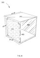
- FIG. 3 depicts an exploded view of a single prismatic box-like structure
- FIG. 4 depicts an exploded view of an inside of a single prismatic box-like structure
- FIG. 5 depicts an exploded view of a method for attaching two prismatic box-like structures horizontally
- FIG. 6 depicts an exploded view of a single garden box displaceably disposed inside one of the prismatic box-like structures
- FIG. 7 depicts an exploded view of an inside of a single garden box displaceably disposed inside one of the prismatic box-like structures
- FIG. 8 depicts an exploded view of a telescoping system
- FIG. 9 depicts an exploded view of an air bag system
- FIG. 10 depicts an exploded view of a scissor lift system
- FIG. 11 depicts an exploded view of a pulley system
- FIG. 12 depicts an exploded view of a linear actuator system
- FIG. 13 depicts an exploded view of a rack and pinion system
- FIG. 14 depicts an exploded view of one embodiment of a garden box storing a growing medium, and the growing medium divided according to a grid system;
- FIG. 15A depicts an exploded top view of an outline of the grid system
- FIG. 15B depicts an exploded view of a growing medium
- FIG. 15C depicts an exploded view of a bottom wall of each garden box, divided into sections according to a grid system.
- FIG. 16 depicts an exploded view of one embodiment of a garden box equipped with an automated water supply system, an automated gas supply system, an automated temperature control system, an automated shading and light control device, and artificial lighting.
- FIG. 1 depicts one embodiment of a building 100 built in accordance with the invention.
- the architectural style and structure of building 100 is variable.
- the outermost finish of building 100 may comprise any variety of embellishments.
- a roof 110 of building 100 comprises a rooftop greenhouse.
- FIG. 2A and FIG. 2B depict a building infrastructure.
- a building infrastructure is an inner, unseen structural frame of the building.
- FIG. 2A depicts the infrastructure of a roof 200 , which comprises a plurality of conjoining modular building segments 210 , being prismatic box-like structures, each prismatic box-like structure 220 comprising at least three walls, and the prismatic box-like structures 220 being placed side by side horizontally and mechanically attached to form a length and width of the roof of the building infrastructure.
- FIG. 2 B depicts an infrastructure of walls and floors 230 of the building infrastructure.
- the infrastructure of walls and floors 230 is also built from modular building segments, comprising prismatic box-like structures.
- the infrastructure of walls and floors 230 is built using traditional methods that utilize standardized building components that are assembled on site.
- FIG. 3 depicts a single prismatic box-like structure 300 .
- Height, length, and width measurements of the prismatic box-like structure 300 are about four feet and one and one-half inch (1.295400 meters).
- a volume within the walls of the prismatic box-like structure 300 measures about 64 cubic feet (1.81228 cubic meters).
- the height, length, and width measurements of each prismatic box-like structure are important in creating a green or sustainable building.
- One characteristic of a sustainable structure is that it allows for the efficient use of space and space within a space. The inventors believe that the height, length, and width measurements and the volume of the prismatic box-like structures optimizes the usable foot print of the building and the use of space within the building.
- the skeletal box-like frame infrastructure of the building unlike prior art column and beam based infrastructures, not only supports the building, but it also provides space actually within the infrastructure to accommodate habitation.
- the height, length, and width measurements of the prismatic box-like structures are also optimal for the rooftop greenhouse because a human arm can generally reach a comparable distance, which means that all areas of a garden box inserted inside the prismatic box-like structure would be within a gardener's reach. Furthermore, the garden box would be big enough for plants to grow, but small enough for easy maintenance. Also, because a large number of prismatic box-like structures are present within the infrastructure, each box can be used to create a separate greenhouse growing environment, such that a variety of growing environments can be created on one rooftop. Referring again to FIG.
- walls 310 of prismatic box-like structure 300 comprise an engineered material selected from a group consisting of engineered wood, composite board, particle board, press board, plywood, wood laminates, chip board, oriented strand board (OSB), gypsum board, cement board, transparent wood, and a combination thereof.
- the walls 310 of the prismatic box-like structure 300 are moisture resistant, termite resistant, and fire proofed.
- At least one wall of the prismatic box-like structure 300 , and at least a top wall of the prismatic box-like structure 300 comprises an optically transparent or semi-optically transparent material, such as glass or transparent wood.
- the optically transparent or semi-optically transparent top wall allows sunlight to penetrate the prismatic box-like structure 300 , so that the sunlight can reach to plants growing inside.
- Walls 310 of prismatic box-like structure 300 are joined together by means of metal plates 320 and brackets 330 mechanically secured along the perimeter of the walls.
- the metal plates 320 are wrapped around two adjoining wall edges and secured with connectors 340 .
- the walls 310 of the prismatic box-like structure 300 are joined together at top and bottom edges with metal brackets 330 that are secured by connectors 350 .
- the connectors 340 and 350 may include screws, bolts, rivet nuts, T-nuts, or other durable connectors, some of which are removable, and some of which are not.
- FIG. 4 depicts an inside view of the single prismatic box-like structure 300 .
- a bottom portion of each prismatic box-like structure 300 is layered with a thin insulation 400 .
- This thin insulation 400 is selected from a group comprising rigid foam insulations, aerogel insulations, and spray foam insulations. Because a space between the walls 310 of each prismatic box-like structure 300 and walls of each garden box inside measures less than one inch (2.54 centimeters), the thin insulation 400 must also be less than one inch (2.54 centimeters) in thickness.
- at least one wall of each prismatic box-like structure 300 comprises a light-reflecting material 410 .
- the light-reflecting material 410 such as a mirror, is attached to an inner portion of the walls 310 of the prismatic box-like structure 300 .
- the light-reflecting material 410 on the walls 310 of the prismatic box-like structure 300 helps to reflect light through the walls of the garden boxes to the plants inside.
- the walls of the garden boxes are opaque.
- the inner walls of the prismatic box-like structures do not comprise light-reflecting material.
- the inner walls of the garden boxes comprise a light-reflecting material instead of the inner walls of the prismatic box-like structures.
- prismatic box-like structures 500 and 510 are mechanically attached horizontally by being fastened together with connector 520 spanning between two areas 530 designated for connecting any two horizontally adjoining prismatic box-like structures.
- the connectors 520 may be screwed or fastened by robots, so that this process is automated and can be accomplished very quickly.
- connectors 520 are screws and the two areas 530 designated for connecting any two horizontally adjoining prismatic box-like structures are central holes of two T-nuts.
- FIG. 6 depicts a single garden box 600 displaceably disposed inside one of the prismatic box-like structures 610 .
- a space 620 between the walls 630 of each prismatic box-like structure and walls 640 of each garden box measures less than one inch (2.54 centimeters).
- Each garden box 600 is connected to a top wall 650 of each prismatic box-like structure 610 .
- the top wall 650 of the prismatic box-like structure 610 is also the top wall of the garden box 600 .
- At least one wall of each garden box 600 , and at least a top wall of each garden box 600 comprises an optically transparent or semi-optically transparent material, such as glass or transparent wood.
- the optically transparent or semi-optically transparent top wall allows sunlight to penetrate the garden box 600 , so that sunlight can reach to plants growing inside.
- all of the walls 640 of the garden boxes 600 comprise optically transparent or semi-optically transparent material.
- the walls 640 of the garden boxes 600 comprise other materials, such as engineered wood products and plastics.
- FIG. 7 depicts an inside view of garden box 600 .
- at least one wall 640 of each garden box 600 comprises a light-reflecting material 700 .
- the light-reflecting material 700 such as a mirror, is attached to an inner portion of the walls 640 of the garden boxes 600 .
- the light-reflecting material 700 on the walls 640 of each garden box 600 helps to reflect light through the walls 640 of the garden boxes 600 to the plants inside.
- the light-reflecting material 700 is used in embodiments where the walls 640 of garden boxes 600 are not optically transparent or semi-optically transparent. In certain embodiments, all of the walls 640 of the garden boxes 600 are optically transparent or semi-optically transparent.
- the inner walls of the garden boxes 600 do not comprise light-reflecting material 700 .
- the inner walls of the prismatic box-like structures comprise a light-reflecting material instead of the inner walls of the garden boxes.
- At least one wall of each garden box 600 comprises an opening that allows access to a space within each garden box. As depicted in FIG. 7 , in one embodiment, the opening replaces one full wall of the garden box. In other embodiments, the opening comprises a sealable hatch or a sealable door or a window or a hole.
- FIG. 8-13 depict the prismatic box-like structures equipped with a mechanism for lifting the garden boxes together with the top wall of the prismatic box-like structures.
- the mechanism for lifting is selected from a group comprising hydraulic and pneumatic telescoping, air bags, scissor lifts, pulley systems, linear actuators, and rack and pinion devices.
- the mechanism for lifting allows the garden boxes to be lifted so that they can be accessed, and also so that gardeners are not subject to back strain that results from hunching down over a garden bed.
- FIG. 8 depicts a telescoping system, powered by hydraulics or pneumatics.
- Telescoping rods 800 are secured in each corner of the prismatic box-like structure 810 .
- the telescoping rods 800 are attached to the top wall 820 of the prismatic box-like structure 810 .
- the telescoping rods 800 rise, lifting the top wall 820 of the prismatic box-like structure 810 .
- Garden box 830 which is attached to the top wall 820 of the prismatic box-like structure 810 , rises with the top wall 820 of the prismatic box-like structure 810 .
- FIG. 9 depicts an air bag system.
- An air bag 900 is sandwiched between prismatic box-like structure 910 and garden box 920 .
- garden box 920 rises.
- FIG. 10 depicts a scissor lift system.
- a scissor lift 1000 is inserted in the space between the walls of each prismatic box-like structure 1010 and walls of each garden box 1020 .
- the scissor lift 1000 is equipped with a motor and a pulley. When the motor is activated, the pulley lifts arms of the scissor lift 1000 , which are attached to the top wall of prismatic box-like structure 1010 , which is attached to garden box 1020 . When the scissor lift 1000 is extended, garden box 1020 rises out of prismatic box-like structure 1010 .
- FIG. 11 depicts a pulley system.
- a pulley 1100 is secured underneath garden box 1120 .
- garden box 1120 is lifted out of prismatic box-like structure 1110 .
- FIG. 12 depicts a linear actuator system.
- a linear actuator 1200 is secured in each corner of the prismatic box-like structure 1210 .
- the linear actuator 1200 is attached to the top wall 1220 of the prismatic box-like structure 1210 .
- Each linear actuator 1200 is equipped with a motor 1240 .
- the motor 1240 When the motor 1240 is activated, the linear actuator 1200 rises, lifting the top wall 1220 of the prismatic box-like structure 1210 .
- Garden box 1230 which is attached to the top wall 1220 of the prismatic box-like structure 1210 , rises with the top wall 1220 of the prismatic box-like structure 1210 .
- FIG. 13 depicts a rack and pinion system.
- a rack 1300 is secured in each corner of prismatic box-like structure 1310 .
- a pinion 1320 is secured on each bottom corner of garden box 1330 .
- gears of the pinion 1320 engage with teeth of the rack 1300 , linear motion is created, lifting garden box 1330 out of prismatic box-like structure 1310 .
- FIG. 14 depicts one embodiment of garden box 1400 .
- garden box 1400 stores a growing medium 1410 selected from a group comprising natural and synthetic soil and natural and synthetic soil alternatives. In other embodiments that use hydroponic or aeroponic systems, no growing medium is necessary.
- Garden box 1400 is also equipped with a grid system 1420 that divides the garden box 1400 , and therefore also the growing medium 1410 , into sections.
- FIG. 14 depicts a top view of an outline of the grid system 1420 .
- the grid system 1420 is not actually visible from this view.
- the grid system 1420 may comprise a processor for controlling growing conditions within the garden box 1400 .
- the processor may be connected to an automated water supply system, an automated gas supply system, an automated temperature control system, an automated shading and light control device, and artificial lighting.
- FIG. 15A , FIG. 15B , and FIG. 15C depict an exploded view of the grid system 1420 and the growing medium 1410 .
- FIG. 15A depicts a top view of an outline of the grid system 1420 . The grid system is not actually visible from a top view due to the presence of a growing medium.
- FIG. 15B depicts a growing medium 1410 . The growing medium 1410 is selected from a group comprising natural and synthetic soil and natural and synthetic soil alternatives.
- FIG. 15C depicts a bottom wall 1510 of each garden box. The bottom wall 1510 is unseen from a top view of the garden box if the garden box stores a growing medium. Therefore, the grid system 1420 may be unseen unless observed from underneath each garden box.
- Each bottom wall 1510 of each garden box is divided into sections according to grid system 1420 .
- the sections are marked by metal rods 1520 equipped with automated sensors connected to a processor, not shown.
- Each section receives different determined amounts of nutrients, water, and gas based on the nature, variety, and quantity of plants within the garden boxes.
- the different determined amounts of nutrients, water, and gas are monitored by the automated sensors within the grid system and the processor controls growing conditions within the garden box based on inputs from the sensors.
- FIG. 16 depicts one embodiment of one garden box 1600 equipped with an automated water supply system, an automated gas supply system, and an automated temperature control system.
- water is supplied by utilizing hydroponic or aeroponic techniques.
- drip irrigation, sprinkler, and misting systems are used.
- FIG. 16 depicts a sprinkler system 1610 .
- the gas supply system utilizes intake air ducts with one-way vent fans located throughout the building. Gases that are beneficial for a growing environment, such as carbon dioxide and nitrogen, are captured and delivered to the garden boxes through vents 1620 .
- the temperature control system utilizes temperature sensing devices and heat pumps.
- FIG. 16 also depicts a temperature sensing device 1630 . Air ducts connect the heat pumps to the garden boxes.
- Each air duct is equipped with an air valve that controls the release of air into the garden boxes.
- the water supply, the air supply, and the temperature of each garden box is controlled separately. This allows gardeners to create a variety of growing environments on just one rooftop. Because the garden boxes move up and down, flexible pipe connections are utilized.
- FIG. 16 depicts an automated shading and light control device 1640 attached to the top wall of the prismatic box-like structure and garden box 1600 .
- the automated shading and light control device 1640 controls how much sunlight enters each garden box. This also helps to control temperature within the garden box.
- the garden boxes are further equipped with artificial lighting 1650 , so that light can be controlled inside and outside.
Landscapes
- Life Sciences & Earth Sciences (AREA)
- Environmental Sciences (AREA)
- Engineering & Computer Science (AREA)
- Architecture (AREA)
- Civil Engineering (AREA)
- Structural Engineering (AREA)
- Physics & Mathematics (AREA)
- Electromagnetism (AREA)
- Acoustics & Sound (AREA)
- Cultivation Receptacles Or Flower-Pots, Or Pots For Seedlings (AREA)
Abstract
Description
Claims (18)
Priority Applications (1)
| Application Number | Priority Date | Filing Date | Title |
|---|---|---|---|
| US15/168,557 US9655309B1 (en) | 2016-05-31 | 2016-05-31 | Rooftop greenhouse inside roof infrastructure |
Applications Claiming Priority (1)
| Application Number | Priority Date | Filing Date | Title |
|---|---|---|---|
| US15/168,557 US9655309B1 (en) | 2016-05-31 | 2016-05-31 | Rooftop greenhouse inside roof infrastructure |
Publications (1)
| Publication Number | Publication Date |
|---|---|
| US9655309B1 true US9655309B1 (en) | 2017-05-23 |
Family
ID=58708733
Family Applications (1)
| Application Number | Title | Priority Date | Filing Date |
|---|---|---|---|
| US15/168,557 Active - Reinstated US9655309B1 (en) | 2016-05-31 | 2016-05-31 | Rooftop greenhouse inside roof infrastructure |
Country Status (1)
| Country | Link |
|---|---|
| US (1) | US9655309B1 (en) |
Cited By (3)
| Publication number | Priority date | Publication date | Assignee | Title |
|---|---|---|---|---|
| CN107197767A (en) * | 2017-05-25 | 2017-09-26 | 广州绿渊生态科技有限公司 | Plant growth system |
| US10681881B2 (en) | 2016-09-19 | 2020-06-16 | Econow Systems, LLC | Apparatus and method for automated aeroponic systems for growing plants |
| DE102022123233A1 (en) | 2022-09-12 | 2024-03-14 | Tom Peter Georg Wiederschein | Plant growing facility |
Citations (35)
| Publication number | Priority date | Publication date | Assignee | Title |
|---|---|---|---|---|
| US4118892A (en) * | 1976-02-06 | 1978-10-10 | Sekisui Kagaku Kogyo Kabushiki Kaisha | Connectable nursery box structures having compartmentalizing grids |
| US4151680A (en) * | 1977-05-23 | 1979-05-01 | Sena August M | Modular horticultural structure |
| US4291494A (en) * | 1979-08-01 | 1981-09-29 | Knablein David J | Indoor greenhouse |
| US4291493A (en) * | 1980-01-07 | 1981-09-29 | Eugene Monson | Apparatus for sprouting seeds |
| US4299054A (en) * | 1979-07-20 | 1981-11-10 | Ware R Louis | Hydroponic assembly and wafer for use therein |
| US4531324A (en) * | 1983-10-07 | 1985-07-30 | Agracetus | Plant tissue culture device |
| US4926586A (en) * | 1986-10-23 | 1990-05-22 | Mutuo Nagamatsu | Box for cultivating plant |
| US4961284A (en) * | 1988-09-09 | 1990-10-09 | Bruce Williams | Vertical garden |
| US5050755A (en) * | 1990-03-28 | 1991-09-24 | Strawder Glenn G | Modular receptacles such as trash cans |
| US5187894A (en) * | 1990-10-09 | 1993-02-23 | The Greenway Services, Inc. | Turfing systems for stadia |
| US5419080A (en) * | 1991-02-01 | 1995-05-30 | Gardener's Supply | Multi-celled tray for growing plants |
| US5467555A (en) * | 1994-10-24 | 1995-11-21 | Greentech, L.L.C. | Turfing systems for stadia |
| US5564226A (en) * | 1995-10-26 | 1996-10-15 | Paramest; Sam | Convertible planter set |
| US5581936A (en) * | 1995-06-27 | 1996-12-10 | Belgiorno; Carlo | Plant propagation trays having inverted V-shaped aerated root separators |
| USD409947S (en) * | 1998-05-13 | 1999-05-18 | Emplast, Inc. | Seed germination tray and cover |
| US5953859A (en) * | 1996-10-16 | 1999-09-21 | Insta-Bed Floral Systems | Rechargeable live planter assembly and method of use thereof |
| US6536361B1 (en) * | 2001-10-10 | 2003-03-25 | Tung-Yuan Wu | Combinable planting plate |
| US20050155287A1 (en) * | 2004-01-15 | 2005-07-21 | Phillips Steven C. | Container system for growing plants |
| US20070094927A1 (en) * | 2005-10-31 | 2007-05-03 | Michael Perry | Rooftop vegetation pod |
| US20080302006A1 (en) * | 2005-12-07 | 2008-12-11 | Flitwick B.V. | Method and Container for Substrate-Free Cultivation of a Germination Product |
| US20090320364A1 (en) * | 2007-01-15 | 2009-12-31 | Mackenzie David S | Modular planting system for roof applications |
| US20100095586A1 (en) * | 2008-09-18 | 2010-04-22 | Eco Innovations Inc. | Plant propagation and display panel and assembly |
| US7726071B2 (en) * | 2006-01-09 | 2010-06-01 | Columbia Green Technologies, Inc. | Vegetation roofing system |
| US20110030274A1 (en) * | 2008-04-29 | 2011-02-10 | Bioroof Systems Inc. | Green roof system with biodegradable vegetation tray |
| US20110036008A1 (en) * | 2007-08-21 | 2011-02-17 | Suntory Holdings Limited | Planting container |
| US20110192084A1 (en) * | 2010-02-05 | 2011-08-11 | Mackenzie David S | Wall planting system |
| US8122682B2 (en) * | 2002-08-29 | 2012-02-28 | American Builders & Contractors Supply Company, Inc. | Modular ballast system for membrane roofs |
| US8132367B2 (en) * | 2009-02-03 | 2012-03-13 | Waldo & Associates, Inc. | Container for growing plants |
| US20120186148A1 (en) * | 2011-01-21 | 2012-07-26 | Hsiao-An Chang | Power-saving flowerpots capable of serial connecting with other flowerpot |
| US20120240463A1 (en) * | 2009-10-29 | 2012-09-27 | Soprema | Modular planting and cultivating container and system and revegetation method using such containers |
| US8707618B2 (en) * | 2007-01-15 | 2014-04-29 | Hortech, Inc. | Modular planting system for roof applications |
| US8739497B2 (en) * | 2011-09-02 | 2014-06-03 | Paul Duggan Meuser | Roofing apparatus |
| US20140325904A1 (en) * | 2013-05-01 | 2014-11-06 | Glen D. Brown | Plywood garden container |
| US8959834B2 (en) * | 2009-11-10 | 2015-02-24 | Suntory Holdings Limited | Plant cultivation container |
| US9265200B2 (en) * | 2012-06-13 | 2016-02-23 | Bioroof Systems Inc. | Modular vegetated roof system |
-
2016
- 2016-05-31 US US15/168,557 patent/US9655309B1/en active Active - Reinstated
Patent Citations (35)
| Publication number | Priority date | Publication date | Assignee | Title |
|---|---|---|---|---|
| US4118892A (en) * | 1976-02-06 | 1978-10-10 | Sekisui Kagaku Kogyo Kabushiki Kaisha | Connectable nursery box structures having compartmentalizing grids |
| US4151680A (en) * | 1977-05-23 | 1979-05-01 | Sena August M | Modular horticultural structure |
| US4299054A (en) * | 1979-07-20 | 1981-11-10 | Ware R Louis | Hydroponic assembly and wafer for use therein |
| US4291494A (en) * | 1979-08-01 | 1981-09-29 | Knablein David J | Indoor greenhouse |
| US4291493A (en) * | 1980-01-07 | 1981-09-29 | Eugene Monson | Apparatus for sprouting seeds |
| US4531324A (en) * | 1983-10-07 | 1985-07-30 | Agracetus | Plant tissue culture device |
| US4926586A (en) * | 1986-10-23 | 1990-05-22 | Mutuo Nagamatsu | Box for cultivating plant |
| US4961284A (en) * | 1988-09-09 | 1990-10-09 | Bruce Williams | Vertical garden |
| US5050755A (en) * | 1990-03-28 | 1991-09-24 | Strawder Glenn G | Modular receptacles such as trash cans |
| US5187894A (en) * | 1990-10-09 | 1993-02-23 | The Greenway Services, Inc. | Turfing systems for stadia |
| US5419080A (en) * | 1991-02-01 | 1995-05-30 | Gardener's Supply | Multi-celled tray for growing plants |
| US5467555A (en) * | 1994-10-24 | 1995-11-21 | Greentech, L.L.C. | Turfing systems for stadia |
| US5581936A (en) * | 1995-06-27 | 1996-12-10 | Belgiorno; Carlo | Plant propagation trays having inverted V-shaped aerated root separators |
| US5564226A (en) * | 1995-10-26 | 1996-10-15 | Paramest; Sam | Convertible planter set |
| US5953859A (en) * | 1996-10-16 | 1999-09-21 | Insta-Bed Floral Systems | Rechargeable live planter assembly and method of use thereof |
| USD409947S (en) * | 1998-05-13 | 1999-05-18 | Emplast, Inc. | Seed germination tray and cover |
| US6536361B1 (en) * | 2001-10-10 | 2003-03-25 | Tung-Yuan Wu | Combinable planting plate |
| US8122682B2 (en) * | 2002-08-29 | 2012-02-28 | American Builders & Contractors Supply Company, Inc. | Modular ballast system for membrane roofs |
| US20050155287A1 (en) * | 2004-01-15 | 2005-07-21 | Phillips Steven C. | Container system for growing plants |
| US20070094927A1 (en) * | 2005-10-31 | 2007-05-03 | Michael Perry | Rooftop vegetation pod |
| US20080302006A1 (en) * | 2005-12-07 | 2008-12-11 | Flitwick B.V. | Method and Container for Substrate-Free Cultivation of a Germination Product |
| US7726071B2 (en) * | 2006-01-09 | 2010-06-01 | Columbia Green Technologies, Inc. | Vegetation roofing system |
| US20090320364A1 (en) * | 2007-01-15 | 2009-12-31 | Mackenzie David S | Modular planting system for roof applications |
| US8707618B2 (en) * | 2007-01-15 | 2014-04-29 | Hortech, Inc. | Modular planting system for roof applications |
| US20110036008A1 (en) * | 2007-08-21 | 2011-02-17 | Suntory Holdings Limited | Planting container |
| US20110030274A1 (en) * | 2008-04-29 | 2011-02-10 | Bioroof Systems Inc. | Green roof system with biodegradable vegetation tray |
| US20100095586A1 (en) * | 2008-09-18 | 2010-04-22 | Eco Innovations Inc. | Plant propagation and display panel and assembly |
| US8132367B2 (en) * | 2009-02-03 | 2012-03-13 | Waldo & Associates, Inc. | Container for growing plants |
| US20120240463A1 (en) * | 2009-10-29 | 2012-09-27 | Soprema | Modular planting and cultivating container and system and revegetation method using such containers |
| US8959834B2 (en) * | 2009-11-10 | 2015-02-24 | Suntory Holdings Limited | Plant cultivation container |
| US20110192084A1 (en) * | 2010-02-05 | 2011-08-11 | Mackenzie David S | Wall planting system |
| US20120186148A1 (en) * | 2011-01-21 | 2012-07-26 | Hsiao-An Chang | Power-saving flowerpots capable of serial connecting with other flowerpot |
| US8739497B2 (en) * | 2011-09-02 | 2014-06-03 | Paul Duggan Meuser | Roofing apparatus |
| US9265200B2 (en) * | 2012-06-13 | 2016-02-23 | Bioroof Systems Inc. | Modular vegetated roof system |
| US20140325904A1 (en) * | 2013-05-01 | 2014-11-06 | Glen D. Brown | Plywood garden container |
Cited By (3)
| Publication number | Priority date | Publication date | Assignee | Title |
|---|---|---|---|---|
| US10681881B2 (en) | 2016-09-19 | 2020-06-16 | Econow Systems, LLC | Apparatus and method for automated aeroponic systems for growing plants |
| CN107197767A (en) * | 2017-05-25 | 2017-09-26 | 广州绿渊生态科技有限公司 | Plant growth system |
| DE102022123233A1 (en) | 2022-09-12 | 2024-03-14 | Tom Peter Georg Wiederschein | Plant growing facility |
Similar Documents
| Publication | Publication Date | Title |
|---|---|---|
| US10736275B2 (en) | Modular, movable, versatile, vertical greenhouse | |
| JP6567416B2 (en) | Hydroponic cultivation system, and plant factory comprising the hydroponic cultivation system and a polystyrene foam house | |
| US9655309B1 (en) | Rooftop greenhouse inside roof infrastructure | |
| AU2015208422B2 (en) | Container for supplying plant roots with nutrient solution without the use of soil | |
| KR101479400B1 (en) | Multipurpose greenhouse dome | |
| US20180098513A1 (en) | Growth Efficiency System | |
| US20180168110A1 (en) | Facilities and method for cultivating plants | |
| JP2003180158A (en) | Cultivation apparatus for mushroom and plant | |
| CA2711092C (en) | Add-on greenhouse for rooms | |
| US11350575B2 (en) | Adjustable system and apparatus for promoting plant growth and production with suspended emitters | |
| ES2654168B1 (en) | DEPOSIT TO HOST A VERTICAL FARM | |
| CN205844955U (en) | A kind of green house of vegetables automated system | |
| RU104820U1 (en) | MODULAR ELEMENT AND DESIGN OF HYDROPONIC INSTALLATION OF MIXED TYPE FOR VERTICAL GARDENING | |
| CN208850331U9 (en) | Annual high-efficient posture three-dimensional cultivation canopy of mushroom | |
| KR200417366Y1 (en) | Hothouse having a multi-roof | |
| JP6602920B1 (en) | Concrete mushroom cultivation system | |
| CN205431264U (en) | Solar energy plant factory greenhouse | |
| KR20090124475A (en) | Vinyl house for agricultural and there of establishing method | |
| JP6489602B2 (en) | Building greening structure and building greening system | |
| JP2007195478A (en) | Facility for mushroom cultivation | |
| JP2003210036A (en) | Mushroom cultivation ridge and mushroom cultivation shelf | |
| KR200416039Y1 (en) | Mobile interior garden | |
| JP2010263807A (en) | Greening structure and method for constructing the same | |
| KR20160061928A (en) | Building Installed Inside Terraced Field | |
| RU2550599C2 (en) | Greenhouse complex for far north regions (device and method) |
Legal Events
| Date | Code | Title | Description |
|---|---|---|---|
| STCF | Information on status: patent grant |
Free format text: PATENTED CASE |
|
| AS | Assignment |
Owner name: HALL LABS LLC, UTAH Free format text: ASSIGNMENT OF ASSIGNORS INTEREST;ASSIGNOR:HALL, DAVID R.;REEL/FRAME:047058/0053 Effective date: 20180911 |
|
| AS | Assignment |
Owner name: HALL LABS LLC, UTAH Free format text: ASSIGNMENT OF ASSIGNORS INTEREST;ASSIGNOR:HALL, DAVID R.;REEL/FRAME:047132/0022 Effective date: 20180911 |
|
| AS | Assignment |
Owner name: HALL LABS LLC, UTAH Free format text: ASSIGNMENT OF ASSIGNORS INTEREST;ASSIGNOR:PRIDDIS, EIMI;REEL/FRAME:048139/0264 Effective date: 20190125 |
|
| FEPP | Fee payment procedure |
Free format text: MAINTENANCE FEE REMINDER MAILED (ORIGINAL EVENT CODE: REM.); ENTITY STATUS OF PATENT OWNER: SMALL ENTITY |
|
| LAPS | Lapse for failure to pay maintenance fees |
Free format text: PATENT EXPIRED FOR FAILURE TO PAY MAINTENANCE FEES (ORIGINAL EVENT CODE: EXP.); ENTITY STATUS OF PATENT OWNER: SMALL ENTITY |
|
| STCH | Information on status: patent discontinuation |
Free format text: PATENT EXPIRED DUE TO NONPAYMENT OF MAINTENANCE FEES UNDER 37 CFR 1.362 |
|
| FP | Lapsed due to failure to pay maintenance fee |
Effective date: 20210523 |
|
| PRDP | Patent reinstated due to the acceptance of a late maintenance fee |
Effective date: 20210818 |
|
| FEPP | Fee payment procedure |
Free format text: SURCHARGE, PETITION TO ACCEPT PYMT AFTER EXP, UNINTENTIONAL. (ORIGINAL EVENT CODE: M2558); ENTITY STATUS OF PATENT OWNER: SMALL ENTITY Free format text: PETITION RELATED TO MAINTENANCE FEES GRANTED (ORIGINAL EVENT CODE: PMFG); ENTITY STATUS OF PATENT OWNER: SMALL ENTITY Free format text: PETITION RELATED TO MAINTENANCE FEES FILED (ORIGINAL EVENT CODE: PMFP); ENTITY STATUS OF PATENT OWNER: SMALL ENTITY |
|
| MAFP | Maintenance fee payment |
Free format text: PAYMENT OF MAINTENANCE FEE, 4TH YR, SMALL ENTITY (ORIGINAL EVENT CODE: M2551); ENTITY STATUS OF PATENT OWNER: SMALL ENTITY Year of fee payment: 4 |
|
| STCF | Information on status: patent grant |
Free format text: PATENTED CASE |