US9654390B2 - Method and apparatus for improving cloud routing service performance - Google Patents
Method and apparatus for improving cloud routing service performance Download PDFInfo
- Publication number
- US9654390B2 US9654390B2 US14/016,435 US201314016435A US9654390B2 US 9654390 B2 US9654390 B2 US 9654390B2 US 201314016435 A US201314016435 A US 201314016435A US 9654390 B2 US9654390 B2 US 9654390B2
- Authority
- US
- United States
- Prior art keywords
- router
- logical
- mode change
- software
- hardware
- Prior art date
- Legal status (The legal status is an assumption and is not a legal conclusion. Google has not performed a legal analysis and makes no representation as to the accuracy of the status listed.)
- Active, expires
Links
Images


Classifications
-
- H—ELECTRICITY
- H04—ELECTRIC COMMUNICATION TECHNIQUE
- H04L—TRANSMISSION OF DIGITAL INFORMATION, e.g. TELEGRAPHIC COMMUNICATION
- H04L45/00—Routing or path finding of packets in data switching networks
- H04L45/58—Association of routers
- H04L45/586—Association of routers of virtual routers
-
- H—ELECTRICITY
- H04—ELECTRIC COMMUNICATION TECHNIQUE
- H04L—TRANSMISSION OF DIGITAL INFORMATION, e.g. TELEGRAPHIC COMMUNICATION
- H04L45/00—Routing or path finding of packets in data switching networks
- H04L45/56—Routing software
Landscapes
- Engineering & Computer Science (AREA)
- Computer Networks & Wireless Communication (AREA)
- Signal Processing (AREA)
- Data Exchanges In Wide-Area Networks (AREA)
Abstract
In one embodiment, a method includes creating a logical router on a first router, the first router being supported on a first node, the logical router being created for a tenant. The method also includes determining whether a mode change is indicated, and migrating the logical router from the first router to the second router when it is determined that the mode change is indicated. The mode change is associated with migrating the logical router from the first router to a second router, where the second router is also supported on the first node.
Description
The disclosure relates generally to routing and processing packets. More particularly, the disclosure relates to a system within a cloud network that may efficiently switch between a logical cloud router provided as a software router and a logical cloud router provided as a hardware router.
Logical cloud routers used to route packets between tenants associated with a cloud network are often implemented as software-based routers running on a virtual machine, or using constructs such as Linux namespaces. While software-based routers have become increasingly powerful, the packet forwarding performance of software-based routers is generally not as good as the packet forwarding performance of hardware-based routers.
Although logical routers may be implemented as hardware-based routers due to the packet forwarding performance of hardware-based routers, the use of hardware-based routers may be insufficient with regards to handling volumes of traffic. As will be appreciated by those skilled in the art, a virtual context may be created on a hardware router to support an instance of a logical router. The use of software-based routers is generally more scalable than the use of hardware-based routers, as software-based routers may be instantiated in much larger numbers in virtual machines, for example, than virtual contexts may be created in hardware-based routers.
The disclosure will be readily understood by the following detailed description in conjunction with the accompanying drawings in which:
According to one aspect, a method includes creating a logical router on a first router, the first router being supported on a first node, the logical router being created for a tenant. The method also includes determining whether a mode change is indicated, and migrating the logical router from the first router to the second router when it is determined that the mode change is indicated. The mode change is associated with migrating the logical router from the first router to a second router, where the second router is also supported on the first node.
As will be understood by those skilled in the art, a cloud network is generally a scalable, virtual network that interconnects cloud resources, e.g., virtual machines. A cloud network may be constrained to a single tenant or interconnect resources owned by multiple tenants. Routing services provided within a cloud network generally allow packets to be routed between different Internet Protocol (IP) networks.
Logical routers used within a cloud network, or logical cloud routers, may generally be hardware-based or software-based. Hardware-based logical routers may be application specific integrated circuit (ASIC) based logical routers, and are generally characterized by relatively high packet forwarding performance. While software-based logical routers are relatively powerful, the packet forwarding performance of software-based logical routers is not as high as the packet forwarding performance of software-based logical routers. However, software-based logical routers are typically more scalable than hardware-based logical routers. In general, software-based routers in virtual machines may be instantiated in larger numbers that virtual contexts may be created on a hardware-based router.
In one embodiment, a cloud network device may effectively implement a software-based logical cloud when performance and/or service requirements, e.g., packet forwarding performance, may be accomplished using the software-based logical router, and implement a hardware-based logical router when performance and/or service requirements are such that the use of the hardware-based logical router is merited. Such a cloud network device may effectively switch between being used as a hardware router and used as a software router in real-time and/or substantially on-demand, as for example when a mode change trigger which is obtained indicates that a switch is to be made.
By allowing a logical cloud router or a logical router that is associated with a cloud network to be changed, e.g., in real-time and/or substantially on-demand, between operating as a software-based logical router and a hardware-based logical router, an appropriate router may be efficiently selected for use based on current performance specifications. In one embodiment, a logical router may be provided as a hardware-based logical router when performance is critical, and as a software-based logical router when performance is less critical. For example, a cloud network device that is capable of instantiating a software-based logical router and a hardware-based logical router may be configured to create a hardware-based logical router when a relatively high packet forwarding performance is desired, and to create a software-based logical router when a relatively high packet forwarding performance is not necessary.
In one embodiment, a cloud network device or a node includes a hardware router component and a software router component. The node may effectively switch between operating as a hardware router and operating as a software router based on a mode change trigger, or a trigger that is arranged to indicate whether the node is to operate as a hardware router or as a software router. Referring initially to FIG. 1 , a node that supports a hardware router and a software router will be described in accordance with an embodiment. A node 100, which may be a cloud network device such as a computing device, is generally arranged to operate as a router to route packets within a network. Node 100 includes logic 104, a processing arrangement 108, a storage arrangement 112, and an input/output (I/O) interface 116. Logic 104, which may include hardware and/or software logic, includes a hardware router module 116, a software router module 120, a cloud network management system module 124, and a virtual machine module 128.
Cloud network management system module 124 is generally configured to support the operation of hardware router module 116 and software router module 120, as appropriate, to forward packets to and from tenants in a cloud network. Cloud network management system module 124 may instantiate software-based logical routers, e.g., routers running in virtual machines and/or namespaces, as well as hardware-based logical routers, e.g., using virtual contexts. A logical router may be reconfigured by cloud network management system module 124 during run-time. Any suitable method may be used to reconfigure the logical router during run-time. Suitable methods may include, but are not limited to including, utilizing dedicated administrative networks and dedicated network interface cards (NICs) associated with a logical router.
Cloud network management system module 124 includes a layer 3 (L3) service control module 132, and a logical router instantiation module 136. L3 service control module 132 is configured to determine when a logical router is to be migrated from being a software-based logical router to being a hardware-based logical router, and vice versa. In one embodiment, L3 service control module 132 may obtain a trigger arranged to indicate that a logical router is to be migrated from a software router to a hardware router, or vice versa, and effectively configure the logical router in response to the trigger. Logical router instantiation module 136 is arranged to instantiate a logical router on node 100 using either hardware router module 116 or software router module 120.
In one embodiment, a node that is configured to operate as a router may generally operate as a software router, and may effectively switch to operating as a hardware router when certain conditions arise, e.g., when a mode change trigger is obtained. A mode change trigger may generally be associated with, but is not limited to being associated with, the desired performance of a router and/or the demand for routing services. FIG. 2 is a process flow diagram which illustrates a method of switching a node from substantially functioning as a software router to substantially functioning as a hardware router in accordance with an embodiment. A process 201 of effectively transitioning a node from operating as a software router to operating as a hardware router begins at step 205 in which a logical router is created, e.g., effectively instantiated or provided, for a tenant. The logical router is created as a software router the node. As previously mentioned, when the logical router is created as a software router, the logical router may be software-based and running on a virtual machine or a namespace.
Once a logical router is instantiated for a tenant as a software router, a mode change trigger is obtained in step 209. The mode change trigger typically provides an indication that the logical router is to be migrated from operating as the software router on the node to operating as a hardware router on the node.
A mode change trigger may be obtained by an L3 service control module which is part of an overall cloud network service management system on the node from any suitable source. In one embodiment, a mode change trigger may be obtained from a network administrator or generally from within an overall cloud network component that is effectively monitoring the node. A mode change trigger may be substantially obtained from an application programming interface (API) call made by a tenant, a cloud network administrator, and/or a service component associated with a cloud network. By way of example, a mode change trigger may be received by the node as a part of an orchestration process or function. An orchestration process may request and configure cloud resources according to different workflows that are offered as advanced cloud services to customers. The workflow for a relatively high bandwidth data transfer from a customer site to the cloud may first involve the setup of a provider VPN, e.g., a BGP/MPLS L3 VPN with provisioned bandwidth. Once a provider VPN is set up, a logical cloud router may be migrated from software to a hardware router as part of the workflow. Finally, a data transfer may be performed as a part of the workflow. Once that data transfer is complete, the inverse of the workflow may be performed, e.g., a logical cloud router may be migrated from the hardware router to software and a provider VPN may be setup.
After the mode change trigger is obtained, a configuration of the logical router is retrieved in step 213. The configuration of the logical router may be retrieved by the L3 service control module from the logical router itself or from a database. It should be appreciated that, as the logical router is software-based, the configuration of the logical router may effectively be the configuration of a software router.
In step 217, a hardware router associated with the node is prepared for service using a configuration analogous to the configuration of the software router, e.g., the configuration obtained in step 213. That is, the hardware router may be prepared to support the migration of the logical router from the software router to the hardware router. Preparing the hardware router for service may include, but is not limited to including, creating a virtual context for the hardware router.
In one embodiment, process flow may move from step 217 to step 219 in which the L3 service control module may optionally configure a hot standby router protocol (HSRP) or a virtual router redundancy protocol (VRRP) on both the software router and on the hardware router with the software router set as a primary router and the hardware router set as a backup router. In other words, the hardware router may effectively be set as a backup or standby router with respect to the software router.
The hardware router is attached or otherwise connected to the same networks, e.g., logical networks, as the software router in step 221. Attaching the hardware router to networks may involve, in one embodiment, reconfiguring a physical network substrate, as for example L2 switches, such that tenant traffic to and tenant traffic from the networks may be forwarded along suitable paths. Suitable paths may be, for example, paths with appropriate Quality of Service (QoS) properties.
Once the hardware router is attached to the networks, process flow proceeds to step 225 in which the software router is disconnected from the networks to which the hardware router was attached in step 221. That is, the software router is disconnected from the networks that it was routing for. The process of effectively transitioning a node from operating as a software router to operating as a hardware router is completed once the software router is disconnected from the networks.
With reference to FIG. 3 , the operation of a node that may dynamically switch from operating as a software router to operating as a hardware router substantially on-demand during runtime will be described in accordance with an embodiment. A node 300 which has the capability to switch between operating as a software router and a hardware router initially, at a time T1, operates as a software router, or a software-based logical router. At a time T2, node 300 obtains a trigger which effectively indicates that node 300 is to migrate the logical router from a software-based logical router to a hardware-based logical router. After the trigger is obtained, node 300 migrates the logical router from a software-based logical router to a hardware-based logical router at a time T3. At a time T4, node 300 operates as a hardware-based logical router.
Although a node which may operate as a software router and as a hardware router may generally be configured to operate as a software router unless a trigger indicates that the node is to operate as a hardware router, a node may instead operate as a hardware router unless a trigger indicates that the node is to operate as a software router. By way of example, when routing requirements are such that the packet forwarding performance of a hardware router is typically needed, a logical router instantiated on a node may effectively default to being hardware-based. FIG. 4 is a process flow diagram which illustrates a method of switching a node from substantially functioning as a hardware router to substantially functioning as a software router in accordance with an embodiment. A process 401 of effectively transitioning a node from operating as a hardware router to operating as a software router begins at step 405 in which a logical router is created for a tenant. The logical router is created as a hardware-based logical router on the node.
Once a logical router is created for a tenant as a hardware router, a mode change trigger is obtained in step 409. The mode change trigger typically provides an indication that the logical router is to be migrated from being a hardware-based logical router to being a software-based logical router.
A mode change trigger may be obtained from any suitable source by an L3 service control module which is part of an overall cloud network service management system on the node. After the mode change trigger is obtained, a configuration of the logical router is retrieved in step 413. The configuration of the logical router may be retrieved by the L3 service control module from the logical router itself or from a database. It should be appreciated that, as the logical router is a hardware-based logical router, the configuration of the logical router may effectively be the configuration of a hardware router.
In step 417, a software router associated with the node is prepared for service using a configuration analogous to the configuration of the hardware router, e.g., the configuration obtained in step 413. That is, the software router may be prepared to support the migration of the logical router from the hardware router to the software router. Preparing the software router for service may include, but is not limited to including, preparing a virtual machine or namespace to support a software-based logical router.
In one embodiment, process flow may move from step 417 to an optional step 419 in which the L3 service control module may optionally configure a HSRP or a VRRP on both the software router and on the hardware router with the hardware router set as a primary router and the software router set as a backup router. That is, the software router may effectively be set as a backup or standby router with respect to the hardware router.
The software router is attached or otherwise connected to the same networks, e.g., logical networks, as the hardware router in step 421. Attaching the hardware router to networks may involve, in one embodiment, reconfiguring a physical network substrate, as for example L2 switches, such that tenant traffic to and tenant traffic from the networks may be forwarded along suitable paths. Suitable paths may be, for example, paths with appropriate QoS properties.
Once the software router is attached to the networks, process flow proceeds to step 425 in which the hardware router is disconnected from the networks to which the software router was attached in step 421. The process of effectively transitioning a node from operating as a hardware router to operating as a software router is completed once the hardware router is disconnected from the networks.
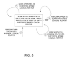
Referring next to FIG. 5 , the operation of a node that supports a hardware router and a software router to switch from acting as a hardware router to acting as a software router will be described in accordance with an embodiment. A node 500 which has the capability to switch between operating as a hardware router and a software router initially, at a time T1, operates as a hardware router, or a hardware-based logical router. At a time T2, node 500 obtains a trigger which effectively indicates that node 500 is to migrate or otherwise transition the logical router from a hardware-based logical router to a software-based logical router. After the trigger is obtained, node 500 migrates the logical router from a hardware-based logical router to a software-based logical router at a time T3. At a time T4, node 500 operates as a software-based logical router.
Although only a few embodiments have been described in this disclosure, it should be understood that the disclosure may be embodied in many other specific forms without departing from the spirit or the scope of the present disclosure. By way of example, a system in which a logical router may be provided as a software-based router or as a hardware-based router, and may be migrated between the two on-demand and/or during runtime has been described as being suitable for use in a cloud network. It should be appreciated that such a system is not limited to being used in a cloud network, and may generally be used in any suitable network.
Any suitable condition may generally trigger a mode change from a software-based logical router to a hardware-based logical router, and vice versa. While a performance-related trigger has generally been described, a mode change is not limited to being triggered based on performance requirements. For example, a mode change may effectively be triggered by a tenant based on any suitable requirements. In one embodiment, a mode change may be triggered based on a time rather than a performance requirement. In another embodiment, a mode change may be triggered for maintenance and/or upgrade reasons.
Cloud service providers may, in one embodiment, use a system which may switch between a software-based logical router and a hardware-based logical router to more efficiently use and allocated their resources, e.g., by creating increased differentiation in their service offerings. Cloud platform users may, in one embodiment, more accurately utilize their virtual resources and achieve higher performance through the use of a system which may switch between a software-based logical router and a hardware-based logical router.
In general, a node with the capability to support a software router and a hardware router may be any suitable router in a cloud network. A node that supports a software router and a hardware router may generally also act as a gateway to the Internet for tenant networks. Such a node may be, in one embodiment, an ASIC-based hardware router that is configured to support a software-based router. Additionally, hardware routers that utilize service blades may be such that a service blade runs a hypervisor and is capable of deploying virtual machines. A software router may run, in one embodiment, substantially inside a hypervisor-based virtual machine. Hypervisor-based virtual machines may include, but are not limited to including, KVM or Xen. In another embodiment, a software router may run substantially inside a container-based virtual environment. Examples of container-based virtual environments include, but are not limited to including, Linux LXC, OpenVZ, Namespaces, Solaris Containers, and/or FreeBSD jails.
The embodiments may be implemented as hardware, firmware, and/or software logic embodied in a tangible, i.e., non-transitory, medium that, when executed, is operable to perform the various methods and processes described above. That is, the logic may be embodied as physical arrangements, modules, or components. A tangible medium may be substantially any computer-readable medium that is capable of storing logic or computer program code which may be executed, e.g., by a processor or an overall computing system, to perform methods and functions associated with the embodiments. Such computer-readable mediums may include, but are not limited to including, physical storage and/or memory devices. Executable logic may include, but is not limited to including, code devices, computer program code, and/or executable computer commands or instructions.
It should be appreciated that a computer-readable medium, or a machine-readable medium, may include transitory embodiments and/or non-transitory embodiments, e.g., signals or signals embodied in carrier waves. That is, a computer-readable medium may be associated with non-transitory tangible media and transitory propagating signals.
The steps associated with the methods of the present disclosure may vary widely. Steps may be added, removed, altered, combined, and reordered without departing from the spirit of the scope of the present disclosure. Therefore, the present examples are to be considered as illustrative and not restrictive, and the examples is not to be limited to the details given herein, but may be modified within the scope of the appended claims.
Claims (10)
1. A method comprising:
creating a logical router on a first router, the first router being supported on a first node, the logical router being created for a tenant;
determining whether a mode change is indicated, the mode change being associated with migrating the logical router from the first router to a second router, the second router being supported on the first node; and
migrating the logical router from the first router to the second router when it is determined that the mode change is indicated, wherein the first router is a software router and the second router is a hardware router, and wherein determining whether the mode change is indicated includes determining whether a high bandwidth data transfer is planned from a customer site to a cloud.
2. The method of claim 1 further including:
obtaining a mode change trigger, the mode change trigger being arranged to indicate whether the mode change is indicated; and
retrieving a configuration of the logical router when it is determined that the mode change is indicated.
3. The method of claim 1 wherein migrating the logical router from the first router to the second router includes identifying at least one network to which the first router is attached, and attaching the second router to the at least one network.
4. The method of claim 3 wherein migrating the logical router from the first router to the second router further includes disconnecting the first router from the at least one network.
5. A method comprising:
creating a logical router on a first router, the first router being supported on a first node, the logical router being created for a tenant;
determining whether a mode change is indicated, the mode change being associated with migrating the logical router from the first router to a second router, the second router being supported on the first node;
migrating the logical router from the first router to the second router when it is determined that the mode change is indicated;
determining when to migrate the logical router from the second router back to the first router, wherein determining when to migrate the logical router from the second router back to the first router includes determining when a data transfer is complete; and
migrating the logical router from the second router back to the first router when it is determined that the logical router is to migrate from the second router back to the first router, wherein it is determined that the logical router is to migrate from the second router back to the first router when the data transfer is complete.
6. A tangible, non-transitory computer-readable medium comprising computer program code, the computer program code, when executed, configured to:
create a logical router on a first router, the first router being supported on a first node, the logical router being created for a tenant;
determine whether a mode change is indicated, the mode change being associated with migrating the logical router from the first router to a second router, the second router being supported on the first node; and
migrate the logical router from the first router to the second router when it is determined that the mode change is indicated, wherein the first router is a software router and the second router is a hardware router, and wherein the computer program code configured to determine whether the mode change is indicated is configured to determine whether a high bandwidth data transfer is planned from a customer site to a cloud.
7. The tangible, non-transitory computer-readable medium comprising computer program code of claim 6 further configured to:
obtain a mode change trigger, the mode change trigger being arranged to indicate whether the mode change is indicated; and
retrieve a configuration of the logical router when it is determined that the mode change is indicated.
8. The tangible, non-transitory computer-readable medium comprising computer program code of claim 6 wherein the computer program code configured to migrate the logical router from the first router to the second router is further configured to identify at least one network to which the first router is attached and to attach the second router to the at least one network.
9. The tangible, non-transitory computer-readable medium comprising computer program code of claim 8 wherein the computer program code configured to migrate the logical router from the first router to the second router is still further configured to disconnect the first router from the at least one network.
10. A tangible, non-transitory computer-readable medium comprising computer program code, the computer program code, when executed, configured to:
create a logical router on a first router, the first router being supported on a first node, the logical router being created for a tenant;
determine whether a mode change is indicated, the mode change being associated with migrating the logical router from the first router to a second router, the second router being supported on the first node;
migrate the logical router from the first router to the second router when it is determined that the mode change is indicated;
determine when to migrate the logical router from the second router back to the first router, wherein the computer program code configured to determine when to migrate the logical router from the second router back to the first router is configured to determine when a data transfer is complete; and
migrate the logical router from the second router back to the first router when it is determined that the logical router is to migrate from the second router back to the first router, wherein it is determined that the logical router is to migrate from the second router back to the first router when the data transfer is complete.
Priority Applications (4)
| Application Number | Priority Date | Filing Date | Title |
|---|---|---|---|
| US14/016,435 US9654390B2 (en) | 2013-09-03 | 2013-09-03 | Method and apparatus for improving cloud routing service performance |
| CN201480048481.1A CN105556907B (en) | 2013-09-03 | 2014-08-25 | Method and apparatus for improving cloud route service performance |
| PCT/US2014/052527 WO2015034703A1 (en) | 2013-09-03 | 2014-08-25 | Method and apparatus for improving cloud routing service performance |
| EP14766829.7A EP3042474B1 (en) | 2013-09-03 | 2014-08-25 | Method and apparatus for improving cloud routing service performance |
Applications Claiming Priority (1)
| Application Number | Priority Date | Filing Date | Title |
|---|---|---|---|
| US14/016,435 US9654390B2 (en) | 2013-09-03 | 2013-09-03 | Method and apparatus for improving cloud routing service performance |
Publications (2)
| Publication Number | Publication Date |
|---|---|
| US20150063366A1 US20150063366A1 (en) | 2015-03-05 |
| US9654390B2 true US9654390B2 (en) | 2017-05-16 |
Family
ID=51564790
Family Applications (1)
| Application Number | Title | Priority Date | Filing Date |
|---|---|---|---|
| US14/016,435 Active 2034-03-22 US9654390B2 (en) | 2013-09-03 | 2013-09-03 | Method and apparatus for improving cloud routing service performance |
Country Status (4)
| Country | Link |
|---|---|
| US (1) | US9654390B2 (en) |
| EP (1) | EP3042474B1 (en) |
| CN (1) | CN105556907B (en) |
| WO (1) | WO2015034703A1 (en) |
Families Citing this family (5)
| Publication number | Priority date | Publication date | Assignee | Title |
|---|---|---|---|---|
| US10079779B2 (en) * | 2015-01-30 | 2018-09-18 | Nicira, Inc. | Implementing logical router uplinks |
| US11102298B1 (en) | 2015-05-26 | 2021-08-24 | Pure Storage, Inc. | Locally providing cloud storage services for fleet management |
| US10129142B2 (en) | 2015-08-11 | 2018-11-13 | Nicira, Inc. | Route configuration for logical router |
| US10095535B2 (en) | 2015-10-31 | 2018-10-09 | Nicira, Inc. | Static route types for logical routers |
| US10454758B2 (en) | 2016-08-31 | 2019-10-22 | Nicira, Inc. | Edge node cluster network redundancy and fast convergence using an underlay anycast VTEP IP |
Citations (9)
| Publication number | Priority date | Publication date | Assignee | Title |
|---|---|---|---|---|
| US20030031180A1 (en) * | 1999-12-31 | 2003-02-13 | Ragula Systems D/B/A/ Fatpipe Networks | Combining routers to increase concurrency and redundancy in external network access |
| US20070014231A1 (en) * | 2005-07-15 | 2007-01-18 | Kaarthik Sivakumar | Router and method for protocol process migration |
| US20110032830A1 (en) * | 2009-08-06 | 2011-02-10 | Jacobus Van Der Merwe | Live Router Migration |
| US20110075674A1 (en) | 2009-09-30 | 2011-03-31 | Alcatel-Lucent Usa Inc. | Scalable architecture for enterprise extension in a cloud topology |
| US20110075667A1 (en) | 2009-09-30 | 2011-03-31 | Alcatel-Lucent Usa Inc. | Layer 2 seamless site extension of enterprises in cloud computing |
| US20110134931A1 (en) * | 2009-12-08 | 2011-06-09 | Jacobus Van Der Merwe | Virtual router migration |
| US20120151057A1 (en) | 2010-12-03 | 2012-06-14 | Level 3 Communications, Llc | Virtualized connectivity in a cloud services environment |
| US20130044636A1 (en) | 2011-08-17 | 2013-02-21 | Teemu Koponen | Distributed logical l3 routing |
| US20130086200A1 (en) | 2011-10-04 | 2013-04-04 | International Business Machines Corporation | Live Logical Partition Migration with Stateful Offload Connections Using Context Extraction and Insertion |
-
2013
- 2013-09-03 US US14/016,435 patent/US9654390B2/en active Active
-
2014
- 2014-08-25 WO PCT/US2014/052527 patent/WO2015034703A1/en active Application Filing
- 2014-08-25 CN CN201480048481.1A patent/CN105556907B/en active Active
- 2014-08-25 EP EP14766829.7A patent/EP3042474B1/en active Active
Patent Citations (9)
| Publication number | Priority date | Publication date | Assignee | Title |
|---|---|---|---|---|
| US20030031180A1 (en) * | 1999-12-31 | 2003-02-13 | Ragula Systems D/B/A/ Fatpipe Networks | Combining routers to increase concurrency and redundancy in external network access |
| US20070014231A1 (en) * | 2005-07-15 | 2007-01-18 | Kaarthik Sivakumar | Router and method for protocol process migration |
| US20110032830A1 (en) * | 2009-08-06 | 2011-02-10 | Jacobus Van Der Merwe | Live Router Migration |
| US20110075674A1 (en) | 2009-09-30 | 2011-03-31 | Alcatel-Lucent Usa Inc. | Scalable architecture for enterprise extension in a cloud topology |
| US20110075667A1 (en) | 2009-09-30 | 2011-03-31 | Alcatel-Lucent Usa Inc. | Layer 2 seamless site extension of enterprises in cloud computing |
| US20110134931A1 (en) * | 2009-12-08 | 2011-06-09 | Jacobus Van Der Merwe | Virtual router migration |
| US20120151057A1 (en) | 2010-12-03 | 2012-06-14 | Level 3 Communications, Llc | Virtualized connectivity in a cloud services environment |
| US20130044636A1 (en) | 2011-08-17 | 2013-02-21 | Teemu Koponen | Distributed logical l3 routing |
| US20130086200A1 (en) | 2011-10-04 | 2013-04-04 | International Business Machines Corporation | Live Logical Partition Migration with Stateful Offload Connections Using Context Extraction and Insertion |
Non-Patent Citations (1)
| Title |
|---|
| Gupta et al; Improving HPC Application Performance in Cloud through Dynamic Load Balancing; CCGRUD, 2013 13th IEEE/ACM Int. Symposium, IEEE; 2013-05012, pp. 402-409. |
Also Published As
| Publication number | Publication date |
|---|---|
| CN105556907B (en) | 2019-05-10 |
| EP3042474A1 (en) | 2016-07-13 |
| EP3042474B1 (en) | 2020-02-19 |
| US20150063366A1 (en) | 2015-03-05 |
| CN105556907A (en) | 2016-05-04 |
| WO2015034703A1 (en) | 2015-03-12 |
Similar Documents
| Publication | Publication Date | Title |
|---|---|---|
| US11665053B2 (en) | Initializing network device and server configurations in a data center | |
| EP3672169B1 (en) | Facilitating flow symmetry for service chains in a computer network | |
| US11171834B1 (en) | Distributed virtualized computing infrastructure management | |
| US10708082B1 (en) | Unified control plane for nested clusters in a virtualized computing infrastructure | |
| CN111355604B (en) | System and method for user customization and automation operations on software defined networks | |
| US10033584B2 (en) | Automatically reconfiguring physical switches to be in synchronization with changes made to associated virtual system | |
| US10481933B2 (en) | Enabling virtual machines access to switches configured by different management entities | |
| KR101718374B1 (en) | Network function virtualization for a network device | |
| US11153194B2 (en) | Control plane isolation for software defined network routing services | |
| CN112235122A (en) | Automatic selection of software images for network devices | |
| US11258661B2 (en) | Initializing server configurations in a data center | |
| US9654390B2 (en) | Method and apparatus for improving cloud routing service performance | |
| US9225631B2 (en) | Implementation of protocol in virtual link aggregate group | |
| EP3731462B1 (en) | Virtual port group | |
| WO2017167151A1 (en) | Multiple provider framework for virtual switch data planes and data plane migration |
Legal Events
| Date | Code | Title | Description |
|---|---|---|---|
| AS | Assignment |
Owner name: CISCO TECHNOLOGY, INC., CALIFORNIA Free format text: ASSIGNMENT OF ASSIGNORS INTEREST;ASSIGNOR:MELANDER, BOB CHRISTER;REEL/FRAME:031142/0087 Effective date: 20130903 |
|
| STCF | Information on status: patent grant |
Free format text: PATENTED CASE |
|
| MAFP | Maintenance fee payment |
Free format text: PAYMENT OF MAINTENANCE FEE, 4TH YEAR, LARGE ENTITY (ORIGINAL EVENT CODE: M1551); ENTITY STATUS OF PATENT OWNER: LARGE ENTITY Year of fee payment: 4 |