US9633429B2 - Pattern outline extraction device, pattern outline extraction method, and computer program product - Google Patents
Pattern outline extraction device, pattern outline extraction method, and computer program product Download PDFInfo
- Publication number
- US9633429B2 US9633429B2 US14/955,407 US201514955407A US9633429B2 US 9633429 B2 US9633429 B2 US 9633429B2 US 201514955407 A US201514955407 A US 201514955407A US 9633429 B2 US9633429 B2 US 9633429B2
- Authority
- US
- United States
- Prior art keywords
- process condition
- measurement
- variation
- pattern
- outlines
- Prior art date
- Legal status (The legal status is an assumption and is not a legal conclusion. Google has not performed a legal analysis and makes no representation as to the accuracy of the status listed.)
- Active
Links
- 238000000605 extraction Methods 0.000 title claims abstract description 75
- 238000004590 computer program Methods 0.000 title claims description 9
- 238000005259 measurement Methods 0.000 claims abstract description 158
- 238000000034 method Methods 0.000 claims abstract description 158
- 239000000284 extract Substances 0.000 claims abstract description 7
- 238000004364 calculation method Methods 0.000 claims description 44
- 238000013461 design Methods 0.000 claims description 39
- 238000012545 processing Methods 0.000 claims description 20
- 239000004065 semiconductor Substances 0.000 claims description 4
- 230000002093 peripheral effect Effects 0.000 claims description 2
- 238000010586 diagram Methods 0.000 description 20
- 239000000758 substrate Substances 0.000 description 15
- 238000004891 communication Methods 0.000 description 8
- 238000003384 imaging method Methods 0.000 description 7
- 238000005401 electroluminescence Methods 0.000 description 2
- 230000010365 information processing Effects 0.000 description 2
- 230000007261 regionalization Effects 0.000 description 2
- 230000000694 effects Effects 0.000 description 1
- 239000004973 liquid crystal related substance Substances 0.000 description 1
- 238000001459 lithography Methods 0.000 description 1
- 238000012986 modification Methods 0.000 description 1
- 230000004048 modification Effects 0.000 description 1
- 238000001878 scanning electron micrograph Methods 0.000 description 1
- 239000007787 solid Substances 0.000 description 1
- 238000006467 substitution reaction Methods 0.000 description 1
- 238000012360 testing method Methods 0.000 description 1
Images


Classifications
-
- G—PHYSICS
- G06—COMPUTING; CALCULATING OR COUNTING
- G06T—IMAGE DATA PROCESSING OR GENERATION, IN GENERAL
- G06T7/00—Image analysis
- G06T7/10—Segmentation; Edge detection
- G06T7/12—Edge-based segmentation
-
- G—PHYSICS
- G06—COMPUTING; CALCULATING OR COUNTING
- G06T—IMAGE DATA PROCESSING OR GENERATION, IN GENERAL
- G06T7/00—Image analysis
- G06T7/0002—Inspection of images, e.g. flaw detection
- G06T7/0004—Industrial image inspection
- G06T7/0006—Industrial image inspection using a design-rule based approach
-
- G06T7/0085—
-
- G—PHYSICS
- G06—COMPUTING; CALCULATING OR COUNTING
- G06T—IMAGE DATA PROCESSING OR GENERATION, IN GENERAL
- G06T7/00—Image analysis
- G06T7/10—Segmentation; Edge detection
- G06T7/174—Segmentation; Edge detection involving the use of two or more images
-
- G—PHYSICS
- G06—COMPUTING; CALCULATING OR COUNTING
- G06T—IMAGE DATA PROCESSING OR GENERATION, IN GENERAL
- G06T2207/00—Indexing scheme for image analysis or image enhancement
- G06T2207/10—Image acquisition modality
- G06T2207/10056—Microscopic image
- G06T2207/10061—Microscopic image from scanning electron microscope
-
- G—PHYSICS
- G06—COMPUTING; CALCULATING OR COUNTING
- G06T—IMAGE DATA PROCESSING OR GENERATION, IN GENERAL
- G06T2207/00—Indexing scheme for image analysis or image enhancement
- G06T2207/10—Image acquisition modality
- G06T2207/10141—Special mode during image acquisition
- G06T2207/10144—Varying exposure
-
- G—PHYSICS
- G06—COMPUTING; CALCULATING OR COUNTING
- G06T—IMAGE DATA PROCESSING OR GENERATION, IN GENERAL
- G06T2207/00—Indexing scheme for image analysis or image enhancement
- G06T2207/10—Image acquisition modality
- G06T2207/10141—Special mode during image acquisition
- G06T2207/10148—Varying focus
-
- G—PHYSICS
- G06—COMPUTING; CALCULATING OR COUNTING
- G06T—IMAGE DATA PROCESSING OR GENERATION, IN GENERAL
- G06T2207/00—Indexing scheme for image analysis or image enhancement
- G06T2207/20—Special algorithmic details
- G06T2207/20112—Image segmentation details
- G06T2207/20168—Radial search
-
- G—PHYSICS
- G06—COMPUTING; CALCULATING OR COUNTING
- G06T—IMAGE DATA PROCESSING OR GENERATION, IN GENERAL
- G06T2207/00—Indexing scheme for image analysis or image enhancement
- G06T2207/30—Subject of image; Context of image processing
- G06T2207/30108—Industrial image inspection
- G06T2207/30148—Semiconductor; IC; Wafer
Definitions
- Embodiments described herein relate generally to a pattern outline extraction device, a pattern outline extraction method, and a computer program product.
- a semiconductor integrated circuit has come to have various configurations in recent years.
- Various patterns are arranged on a substrate to be processed in order to form such configurations.
- SEM scanning electron microscope
- a method that extracts and evaluates an outline of the pattern from a picked-up SEM image is becoming more predominant. Two-dimensional indices such as an area and a positional deviation can thus be expressed in the numerical form by using the extracted outline.
- FIG. 1 is a block diagram illustrating an example of a configuration of a pattern outline extraction system that includes a pattern outline extraction device according to a first embodiment
- FIG. 2 is a flowchart illustrating an example of a procedure in a pattern outline extraction method according to the first embodiment
- FIG. 3 is a top view illustrating an example of pattern formation on a substrate to be processed
- FIGS. 4A to 4C are diagrams each illustrating an example of the procedure in the pattern outline extraction method according to the first embodiment
- FIGS. 4D and 4E are diagrams each illustrating an example of the procedure in the pattern outline extraction method according to the first embodiment
- FIGS. 5A and 5B are diagrams each illustrating an example of variation-process condition correspondence information
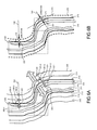
- FIGS. 6A and 6B are diagrams each illustrating another example of the procedure in the pattern outline extraction method according to the first embodiment
- FIGS. 7A and 7B are diagrams each illustrating an example of variation-process condition correspondence information
- FIG. 8 is a block diagram illustrating an example of a configuration of a pattern outline extraction system according to a second embodiment
- FIG. 9 is a flowchart illustrating an example of a procedure in a pattern outline extraction method according to the second embodiment.
- FIGS. 10A and 10B are diagrams each illustrating an example of the procedure in the pattern outline extraction method according to the second embodiment
- FIGS. 10C and 10D are diagrams each illustrating an example of the procedure in the pattern outline extraction method according to the second embodiment.
- FIGS. 11A and 11B are diagrams each illustrating an example of variation-process condition correspondence information.
- a pattern outline extraction device includes a control unit, a secondary storage unit, and a memory.
- the control unit calculates a predicted outline of a pattern acquired under a desired process condition by use of image data of patterns formed by changing a process condition.
- the secondary storage unit stores a program and data executed by the control unit.
- the memory temporarily stores the program and the data stored in the secondary storage unit to be executed by the control unit.
- the control unit reads the image data of the patterns formed by changing the process condition.
- the control unit extracts outlines of the patterns from the image data formed under the process condition, and superposes the outlines.
- the control unit sets straight measurement lines intersecting with the outlines being superposed.
- the control unit calculates variations on the measurement lines relative to measurement points on the measurement lines at points of intersection of the measurement lines and the outlines.
- the control unit calculates variation-process condition correspondence information indicating a relationship between the process conditions and the variations for the measurement lines.
- the control unit calculates predicted variations on the measurement lines relative to the measurement points corresponding to a desired process condition based on the variation-process condition correspondence information.
- the control unit calculates calculated points that are obtained by adding the predicted variations to the measurement points on the measurement lines for the measurement lines. And the control unit calculates a predicted outline by connecting the calculated points.
- a pattern outline extraction device, a pattern outline extraction method, and a computer program product according to embodiments will now be described in detail with reference to the drawings.
- the present invention is not limited to the following embodiments.
- FIG. 1 is a block diagram illustrating an example of a configuration of a pattern outline extraction system including a pattern outline extraction device according to a first embodiment.
- the pattern outline extraction system includes an SEM 10 and a pattern outline extraction device 20 .
- the SEM 10 includes an imaging unit 11 , a storage unit 12 , and a communication unit 13 .
- the imaging unit 11 images a pattern formed on a substrate to be processed by using a lithography technique.
- the pattern on the substrate to be processed is formed under various process conditions.
- An example of the process condition includes an exposure (dose) and a focal position (focus).
- a plurality of patterns formed while changing the exposure or the focal position is formed on the substrate to be processed, and each pattern is imaged by the imaging unit 11 .
- the storage unit 12 stores an image imaged by the imaging unit 11 .
- the storage unit 12 is formed of a non-volatile memory device such as a hard disk drive (HDD) or a solid state drive (SSD).
- the communication unit 13 communicates with the pattern outline extraction device 20 . Here, the communication unit 13 transmits the image stored in the storage unit 12 to the pattern outline extraction device 20 .
- the pattern outline extraction device 20 is configured such that a communication unit 21 , an input unit 22 , a display unit 23 , a memory 24 , a secondary storage unit 25 , and a control unit 26 are connected to one another through a bus 28 .
- the pattern outline extraction device 20 is an information processing device such as a personal computer capable of running a pattern outline extraction program.
- the communication unit 21 performs reception of an image from the SEM 10 .
- the input unit 22 is an input device that inputs an instruction to the pattern outline extraction device 20 .
- the input unit 22 is constituted by a keyboard, a mouse and the like.
- the display unit 23 is a display device capable of displaying an image or video.
- the display unit 23 is a liquid crystal display or an organic electroluminescence (EL) device, for example. Note that the input unit 22 and the display unit 23 may be constituted by a touch panel.
- the memory 24 temporarily stores data and a program used by the control unit 26 when performing control.
- Various types of random access memory (RAM) can be used as the memory 24 .
- the secondary storage unit 25 stores a program 25 a including the pattern outline extraction program executed by the pattern outline extraction device 20 , image data 25 b acquired from the SEM 10 , and variation-process condition correspondence information 25 c to be described.
- the secondary storage unit 25 is an HDD or SSD, for example.
- the control unit 26 loads the program 25 a stored in the secondary storage unit 25 to the memory 24 and executes the program.
- the control unit 26 is constituted by one or a plurality of central processing units (CPUs) and a peripheral circuit.
- the control unit 26 includes an image reading unit 261 , an outline extraction unit 262 , an outline superposition unit 263 , a reference outline data setting unit 264 , a measurement point setting unit 265 , a variation calculation unit 266 , a variation-process condition correspondence information calculation unit 267 , and an outline calculation unit 268 .
- the image reading unit 261 reads the image data 25 b stored in the secondary storage unit 25 .
- the image reading unit reads a plurality of the image data 25 b relevant to a certain pattern formed by changing the process condition.
- the image data 25 b of each pattern acquired by assigning thereto the exposure as the process condition is read, for example.
- the outline cannot be acquired precisely under a desired process condition when the number of the image data 25 b is small. Accordingly, it is desired to use the image data 25 b of patterns formed under no less than five different kinds of process conditions.
- the image reading unit 261 constitutes a reading unit.
- the outline extraction unit 262 extracts an outline of a formed pattern from the image data 25 b being read. Processing performed to extract the outline of the pattern from image data is known and will not be described.
- the outline extraction unit 262 constitutes an outline extraction unit.
- the outline superposition unit 263 superposes the extracted outlines.
- the outline superposition unit calculates a centroid position of the outline and superposes the plurality of outlines such that their centroid positions correspond with one another, for example.
- the outline superposition unit 263 constitutes a superposition unit.
- the reference outline data setting unit 264 sets reference outline data to be a reference among the superposed outlines.
- an outline selected by a user through the input unit 22 is set as the reference outline data.
- it may be adapted to automatically set an outline at a predetermined position as the reference outline data among the plurality of outlines.
- the measurement point setting unit 265 sets a measurement point on the reference outline data.
- the measurement point serves as a reference position when measuring a variation.
- the measurement point setting unit 265 may automatically set a predetermined number of measurement points at a predetermined position on the reference outline data or may set the measurement point at a position selected by the user through the input unit 22 . The larger the number of measurement points being set, the better in order to increase the precision of the outline.
- the variation calculation unit 266 finds a point of intersection of a predetermined straight line passing through the measurement point set on the reference outline data and another outline, and calculates a distance between the measurement point and each point of intersection as the variation.
- the variation calculation unit 266 finds a tangent line at the measurement point on the reference outline data as well as a perpendicular line of the tangent line at the measurement point.
- the variation calculation unit 266 then calculates a distance relative to the measurement point on the perpendicular line at the point of intersection as the variation and stores it in association with a parameter of the process condition.
- the variation calculation unit 266 performs this processing for each measurement point.
- the reference outline data setting unit 264 , the measurement point setting unit 265 and the variation calculation unit 266 constitute a variation calculation unit.
- the variation-process condition correspondence information calculation unit 267 calculates the variation-process condition correspondence information 25 c indicating correspondence between the parameter of the process condition and the variation. Specifically, a combination of the parameter of the process condition and the variation pertaining to a certain perpendicular line is plotted on a coordinate system with a horizontal axis representing the parameter of the process condition and a vertical axis representing the variation. Then, a least squares method is used to calculate an approximation curve of the plotted point. An expression representing the approximation curve is the variation-process condition correspondence information.
- the variation-process condition correspondence information calculation unit 267 saves the calculated variation-process condition correspondence information 25 c in association with the perpendicular line or the measurement point into the secondary storage unit 25 .
- the variation-process condition correspondence information calculation unit 267 constitutes a correspondence information calculation unit.
- the outline calculation unit 268 calculates the variation under a desired process condition for each perpendicular line by using the variation-process condition correspondence information 25 c .
- the outline calculation unit 268 further finds a predicted position obtained by adding the variation to the measurement point on each perpendicular line and calculates a predicted outline by connecting the predicted positions.
- the outline calculation unit 268 then displays the calculated predicted outline on the display unit 23 .
- the outline calculation unit 268 forms an outline calculation unit.
- FIG. 2 is a flowchart illustrating an example of a procedure in the pattern outline extraction method according to the first embodiment.
- FIG. 3 is a top view illustrating an example of pattern formation on the substrate to be processed,
- FIGS. 4A to 4E are diagrams each illustrating an example of a procedure in the pattern outline extraction method according to the first embodiment, and
- FIGS. 5A and 5B are diagrams each illustrating an example of the variation-process condition correspondence information.
- steps S 11 patterns to which the parameters of the process condition are assigned are formed on the substrate to be processed by exposure processing (step S 11 ).
- a shot region is arranged along the X axis and the Y axis.
- the parameter of the process condition is changed in each shot region.
- FIG. 3 illustrates the example where a focal distance is changed along the X axis while the exposure is changed along the Y axis.
- a pattern in a column C 1 of the shot region arranged at the same position along the X axis is formed by the exposure processing that is performed under a condition in which the focal distance stays the same and the exposure increases in a positive direction along the Y axis, for example.
- a pattern in a row R 1 of the shot region arranged at the same position along the Y axis is formed by the exposure processing that is performed under a condition in which the exposure stays the same and the focal distance increases in a positive direction along the X axis. Note that a plurality of patterns is formed on the substrate to be processed by using the same mask but under different process conditions.
- the imaging unit 11 of the SEM 10 images the patterns formed on the substrate to be processed (step S 12 ).
- Image data imaged by the imaging unit 11 is stored in the storage unit 12 .
- the image data stored in the storage unit 12 is transmitted from the communication unit 13 of the SEM 10 to the communication unit 21 of the pattern outline extraction device 20 and stored in the secondary storage unit 25 .
- the image reading unit 261 of the pattern outline extraction device 20 reads the image data 25 b stored in the secondary storage unit 25 , and the outline extraction unit 262 extracts outlines from the image data 25 b (step S 13 ).
- the outline superposition unit 263 superposes the outlines (step S 14 ).
- the outlines are superposed such that centroid positions of acquired outlines 111 to 115 correspond as illustrated in FIG. 4A , for example.
- the superposed outlines 111 to 115 are pattern outlines acquired when the exposure processing is performed on a design 110 of a certain pattern while setting the focal distance to a predetermined value and changing the exposure. Note that the size of the design in a minor axis direction is 60 nm, for example.
- the reference outline data setting unit 264 selects one of the plurality of superposed outlines and sets the outline to be the reference outline data (step S 15 ). As illustrated in FIG. 4B , the outline 113 out of the plurality of outlines 111 to 115 is selected in this case as the reference outline data.
- the measurement point setting unit 265 then sets a measurement point on the reference outline data (step S 16 ). It is assumed as illustrated in FIG. 4C that a single measurement point 121 is set on reference outline data 113 .
- the variation calculation unit 266 finds a tangent line at the measurement point on the reference outline data and draws a line perpendicular to the tangent line at the measurement point (step S 17 ). As illustrated in FIG. 4D , a tangent line 131 is drawn with respect to the measurement point 121 on the reference outline data 113 , and a perpendicular line 141 of the tangent line 131 is drawn with respect to the measurement point 121 .
- the variation calculation unit 266 further calculates distances on the perpendicular line between the reference outline data and another outline as the variations (step S 18 ). Specifically, as illustrated in FIG. 4D , points of intersection 151 - 1 to 151 - 4 of the perpendicular line 141 and the outlines 111 , 112 , 114 , and 115 are found on the perpendicular line 141 . Then, the distance between the measurement point 121 and each of the points of intersection 151 - 1 to 151 - 4 is found on the perpendicular line 141 . In other words, the variation at each of the points of intersection 151 - 1 to 151 - 4 relative to the measurement point 121 is found on the perpendicular line 141 . The variation is associated with the measurement point 121 or the perpendicular line 141 .
- the direction directed outward from the reference outline data 113 is set as a positive direction, while the direction directed inward is set as a negative direction.
- the variation-process condition correspondence information calculation unit 267 graphically represents the variations with respect to the parameters of the process condition (step S 19 ).
- a coordinate system has an X axis representing the exposure as the process condition and a Y axis representing the variation as illustrated in FIGS. 5A and 5B
- a relationship between the exposure and the variation pertaining to a certain perpendicular line is plotted on the coordinate system.
- FIG. 5A is a diagram in which the variation with respect to the exposure for the perpendicular line 141 is plotted.
- the variation-process condition correspondence information calculation unit 267 calculates the variation-process condition correspondence information 25 c obtained by using the least squares method and approximating the relationship between the parameters of the process condition and the variations that are graphically represented (step S 20 ). There is a correlation between the exposure and the variation as illustrated in FIG. 5A , where the approximation between the exposure and the variation is calculated by using the least squares method.
- the calculated variation-process condition correspondence information 25 c is stored in association with the measurement point 121 or the perpendicular line 141 into the secondary storage unit 25 .
- the measurement point setting unit 265 determines whether to set another measurement point (step S 21 ). The procedure returns to step S 16 when setting the other measurement point (Yes in step S 21 ), whereby the aforementioned processing in each of steps S 16 to S 20 is performed.
- a measurement point 122 is set as illustrated in FIG. 4C , for example. Then, as illustrated in FIG. 4D , a tangent line 132 is drawn with respect to the measurement point 122 on the reference outline data 113 , and a perpendicular line 142 of the tangent line 132 is drawn with respect to the measurement point 122 . Points of intersection 152 - 1 to 152 - 4 of the perpendicular line 142 and the outlines 111 , 112 , 114 and 115 are also found, and then a variation from the measurement point 122 at each of the points of intersection 152 - 1 to 152 - 4 is found along the perpendicular line 142 .
- the variation is associated with the measurement point 122 or the perpendicular line 142 .
- the variation along the perpendicular line 142 with respect to the exposure is plotted as illustrated in FIG. 5B , so that the least squares method is used to calculate the variation-process condition correspondence information 25 c on the perpendicular line 142 .
- the outline calculation unit 268 acquires the process condition to acquire a desired design pattern (step S 22 ). Moreover, the outline calculation unit 268 acquires, for each measurement point (perpendicular line), the variation corresponding to the acquired process condition (step S 23 ) by using the variation-process condition correspondence information 25 c for each measurement point.
- the exposure corresponding to the reference outline data 113 equals a 1 and the variation at that time equals r 1 , as illustrated in FIG. 5A .
- the corresponding variation equals r 2 according to the variation-process condition correspondence information 25 c .
- the variation for the desired exposure a 2 equals r 2 -r 1 .
- the exposure corresponding to the reference outline data 113 equals a 1 and the variation at that time equals r 3 , as illustrated in FIG. 5B .
- the corresponding variation equals r 4 according to the variation-process condition correspondence information 25 c .
- the variation for the desired exposure a 2 equals r 4 -r 3 .
- the variation on each perpendicular line for the desired exposure a 2 is calculated in this manner.
- the outline calculation unit 268 finds, as a calculated point, a position away from the reference outline data (measurement point) by the amount corresponding to the acquired variation on the perpendicular line passing through each measurement point (step S 24 ).
- the variation found in step S 23 is added to the measurement points 121 and 122 on the reference outline data 113 along the perpendicular lines 141 and 142 .
- the variation r 2 -r 1 is added outward from the measurement point 121 to find a calculated point 161 .
- the variation r 4 -r 3 is added outward from the measurement point 122 to find a calculated point 162 .
- a calculated point for another perpendicular line is calculated in a similar manner.
- the outline calculation unit 268 then connects the calculated points found in step S 24 and calculates a predicted outline under a desired process condition (step S 25 ). As illustrated in FIG. 4E , for example, by connecting the calculated points 161 and 162 , a predicted outline 160 is calculated. Note that, as is understood from the aforementioned description, precision of the shape of the predicted outline 160 is increased by setting a number of measurement points (perpendicular lines). However, an operation time gets longer as a number of measurement points (perpendicular lines) are set. It is thus desired to set the number of measurement points (perpendicular lines) such that the operation time falls within what is practical. The processing is now completed.
- FIGS. 4A to 4E and 5A and 5B An elliptical aperture pattern is illustrated as an example in FIGS. 4A to 4E and 5A and 5B .
- the first embodiment can be applied to a wiring pattern as well.
- FIGS. 6A and 6B are diagrams each illustrating another example of the procedure in the pattern outline extraction method according to the first embodiment
- FIGS. 7A and 7B are diagrams each illustrating an example of the variation-process condition correspondence information.
- a pattern forming a design 210 it is assumed, for a pattern forming a design 210 , that the exposure processing is performed while setting the focal distance to a predetermined value and assigning the exposure to form the wiring pattern on the substrate to be processed.
- the wiring pattern being formed is imaged by the SEM 10 , and an outline is extracted by the pattern outline extraction device 20 . Then, a plurality of outlines 211 to 215 is superposed as illustrated in FIG. 6A .
- the outline 213 is set as the reference outline data in this case.
- Measurement points 221 and 222 are set on the reference outline data 213 and, with respect to the measurement points 221 and 222 , perpendicular lines 241 and 242 corresponding to tangent lines 231 and 232 are drawn. Points of intersection 251 - 1 to 251 - 4 of the perpendicular line 241 and each of the outlines 211 , 212 , 214 and 215 are found so that a variation relative to the measurement point 221 is found at each of the points of intersection 251 - 1 to 251 - 4 .
- points of intersection 252 - 1 to 252 - 4 of the perpendicular line 242 and each of the outlines 211 , 212 , 214 and 215 are found so that a variation relative to the measurement point 222 is found at each of the points of intersection 252 - 1 to 252 - 4 .
- a relationship between the exposure and the variation for each of the perpendicular lines 241 and 242 is plotted as illustrated in FIGS. 7A and 7B , so that the least squares method is used to calculate the variation-process condition correspondence information 25 c indicating the relationship between the two.
- a variation of the outline relative to the reference outline data 213 is calculated with respect to a desired exposure.
- the perpendicular line 241 for example, it is assumed that the exposure corresponding to the reference outline data 213 equals a 11 and the variation at that time equals r 11 as illustrated in FIG. 7A , in which case the variation under a desired exposure a 12 equals r 12 .
- the variation relative to the reference outline data 213 thus equals r 12 -r 11 .
- the exposure corresponding to the reference outline data 213 equals a 11 and the variation at that time equals r 13 as illustrated in FIG. 7B , in which case the variation under the desired exposure a 12 equals r 14 .
- the variation relative to the reference outline data 213 thus equals r 14 -r 13 .
- calculated points 271 and 272 obtained by adding the variations r 12 -r 11 and r 14 -r 13 to the measurement points 221 and 222 are calculated on the perpendicular lines 241 and 242 of the reference outline data 213 , respectively.
- a predicted outline 270 is thus acquired by connecting the calculated points 271 and 272 .
- the first embodiment is adapted to superpose the outlines of the pattern subjected to the exposure processing under the process condition and set the reference outline data from among the outlines.
- the measurement point is set on the reference outline data, and the perpendicular line is drawn with respect to the tangent line at the measurement point.
- the variation relative to the measurement point is measured at the point of intersection of the perpendicular line and each outline, so that the variation-process condition correspondence information indicating the relationship between the process condition and the variation on each perpendicular line is calculated.
- the variation corresponding to the desired process condition is acquired from the variation-process condition correspondence information for each perpendicular line.
- the method of a related art has been adapted to prepare a number of substrates to be processed having a pattern that is formed by transferring thereto a pattern formed in a mask while changing the depth of focus and exposure, so that the pattern on each substrate to be processed is imaged to extract an outline of the pattern.
- This has required an enormous amount of time in extracting the outline.
- the time required to extract the outline can be cut down compared to the time required in the method of the related art.
- the pattern is formed under the process condition provided to acquire a desired pattern so that the variation of the outlines is acquired. This means that when a pattern is formed under another process condition, a number of patterns formed under the other process condition have been required. In the first embodiment, however, the variation-process condition correspondence information is found so that a change in the outline upon changing the process condition can be acquired without forming a new test pattern.
- the perpendicular line that is perpendicular to the tangent line at the measurement point on the reference outline data is used as the predetermined straight line passing through the measurement point.
- the use of this perpendicular line has been illustrated as an example, where another line may be used as the predetermined straight line passing through the measurement point.
- a straight line passing through the centroid of an outline is used as the predetermined straight line passing through the measurement point.
- FIG. 8 is a block diagram illustrating an example of a configuration of a pattern outline extraction system according to the second embodiment.
- the configuration of the pattern outline extraction system according to the second embodiment is substantially the same as that of the first embodiment described with reference to FIG. 1 , whereby only a part different from the first embodiment will be described.
- a secondary storage unit 25 of a pattern outline extraction device 20 stores a design 25 d in addition to a program 25 a , image data 25 b and variation-process condition correspondence information 25 c .
- the design 25 d is design data on which a pattern to be imaged is based.
- a control unit 26 of the pattern outline extraction device 20 includes an image reading unit 261 , an outline extraction unit 262 , an outline superposition unit 263 , a radial line setting unit 269 , a variation calculation unit 266 , a variation-process condition correspondence information calculation unit 267 , and an outline calculation unit 268 .
- the image reading unit 261 reads the design 25 d along with the image data 25 b .
- the outline superposition unit 263 superposes the design 25 d and an outline extracted from the image data 25 b .
- a method of performing the superposition includes, for example, calculating a centroid position of the design and a centroid position of the outline and then superposing the design and a plurality of outlines such that the centroid positions correspond with one another.
- the radial line setting unit 269 performs processing that draws a predetermined number of radial lines from the centroid position of the design.
- the number of radial lines may be set by a user through an input unit 22 or determined in advance.
- the variation calculation unit 266 finds a measurement point at which the radial line intersects with the design as well as a point of intersection of the radial line and the outline, and calculates a variation relative to the measurement point at each point of intersection.
- the variation calculation unit 266 performs this processing for each radial line.
- the radial line setting unit 269 and the variation calculation unit 266 constitute a variation calculation unit.
- FIG. 9 is a flowchart illustrating an example of a procedure in the pattern outline extraction method according to the second embodiment.
- FIGS. 10A to 10D are diagrams each illustrating an example of the procedure in the pattern outline extraction method according to the second embodiment, and
- FIGS. 11A and 11B are diagrams each illustrating an example of the variation-process condition correspondence information.
- steps S 11 and S 12 in FIG. 2 of the first embodiment patterns to which parameters of a process condition are assigned are formed on a substrate to be processed by exposure processing, and then an SEM 10 images image data of the pattern (steps S 31 and S 32 ).
- the image data is transmitted from the SEM 10 to the pattern outline extraction device 20 and stored in the secondary storage unit 25 .
- the image reading unit 261 of the pattern outline extraction device 20 reads the image data 25 b and the design 25 d stored in the secondary storage unit 25 , and the outline extraction unit 262 extract outlines from the image data 25 b (step S 33 ).
- the outline superposition unit 263 superposes the design 25 d and the extracted outlines (step S 34 ).
- the design and the outlines are superposed such that a centroid position of a design 310 and centroid positions of outlines 311 to 315 correspond as illustrated in FIG. 10A , for example.
- the radial line setting unit 269 draws a predetermined number of straight radial lines from the centroid position of the design (step S 35 ).
- FIG. 10B illustrates an example where 16 straight radial lines 340 are drawn from an origin being a centroid position 321 of the design 310 .
- the variation calculation unit 266 selects one radial line (step S 36 ) and calculates a variation being the distance between the design and the outline on the selected radial line (step S 37 ). It is assumed that a radial line 341 is selected as illustrated in FIG. 10C . In this case, a measurement point 331 that is a point of intersection of the radial line 341 and the design 310 as well as points of intersection 351 - 1 to 351 - 5 of the radial line 341 and the outlines 311 to 315 are found. The variation relative to the measurement point 331 is then calculated at each of the points of intersection 351 - 1 to 351 - 5 . The variation is associated with the radial line 341 or the measurement point 331 .
- the direction directed outward from the design 310 is set as a positive direction
- the direction directed inward (toward the centroid position 321 ) is set as a negative direction.
- the variation-process condition correspondence information calculation unit 267 graphically represents the variations with respect to the parameters of the process condition (step S 38 ).
- a coordinate system has an X axis representing the exposure as the process condition and a Y axis representing the variation as illustrated in FIGS. 11A and 11B
- a relationship between the exposure and the variation is plotted on the coordinate system.
- FIG. 11A is a diagram in which the variation along the radial line 341 with respect to the exposure is plotted.
- the variation-process condition correspondence information calculation unit 267 further calculates the variation-process condition correspondence information 25 c obtained by using the least squares method and approximating the relationship between variations and the parameters of the process condition that are graphically represented (step S 39 ). There is a correlation between the exposure and the variation as illustrated in FIG. 11A , where the approximation between the exposure and the variation is calculated by using the least squares method.
- the calculated variation-process condition correspondence information 25 c is stored in association with the radial line 341 or the measurement point 331 into the secondary storage unit 25 .
- step S 40 the variation calculation unit 266 determines whether there exists another radial line.
- the procedure returns to step S 36 when there exists the other radial line (Yes in step S 40 ), whereby the aforementioned processing in each of steps S 36 to S 39 is performed.
- a radial line 342 is selected as illustrated in FIG. 10D .
- a measurement point 332 that is a point of intersection of the radial line 342 and the design 310 as well as points of intersection 352 - 1 to 352 - 5 of the radial line 342 and the outlines 311 to 315 are found.
- the variation relative to the measurement point 332 on the radial line 342 is then calculated at each of the points of intersection 352 - 1 to 352 - 5 .
- the variation is associated with the radial line 342 or the measurement point 332 .
- the relationship between the exposure and the variation on the radial line 342 is plotted as illustrated in FIG. 11B , so that the least squares method is used to calculate the variation-process condition correspondence information 25 c on the radial line 342 . This processing is performed on all the radial lines.
- the outline calculation unit 268 acquires the process condition to acquire a desired design pattern (step S 41 ). Moreover, the outline calculation unit 268 acquires, for each measurement point or radial line, the variation corresponding to the acquired process condition (step S 42 ) by using the variation-process condition correspondence information 25 c for each measurement point.
- the exposure corresponding to the design 310 equals a 21 and the variation at that time equals r 21 , as illustrated in FIG. 11A .
- the corresponding variation equals r 22 according to the variation-process condition correspondence information 25 c .
- the variation relative to the measurement point 331 under the desired exposure a 22 equals r 22 -r 21 .
- the exposure corresponding to the design 310 equals a 21 and the variation at that time equals r 23 , as illustrated in FIG. 11B .
- the desired exposure equals a 22
- the corresponding variation equals r 24 according to the variation-process condition correspondence information 25 c .
- the variation relative to the measurement point 332 under the desired exposure a 22 equals r 24 -r 23 .
- the variation on each radial line under the desired exposure a 22 is calculated in this manner.
- the outline calculation unit 268 finds, as a calculated point, a position away from the design 310 (measurement point) by the amount corresponding to the acquired variation on the radial line passing through each measurement point (step S 43 ).
- the variation found in step S 42 is added to the measurement points 331 and 332 along the radial lines 341 and 342 .
- the variation r 22 -r 21 is added outward from the measurement point 331 to find a calculated point 361 .
- the variation r 24 -r 23 is added outward from the measurement point 332 to find a calculated point 362 .
- a calculated point for another radial line is calculated in a similar manner.
- the outline calculation unit 268 calculates a predicted outline under a desired process condition (step S 44 ) by connecting the calculated points found in step S 43 .
- the calculated points 361 and 362 are connected to calculate a predicted outline 360 .
- precision of the shape of the predicted outline 360 is increased by setting a number of radial lines.
- an operation time gets longer as a number of radial lines are set. It is thus desired to set the number of radial lines such that the operation time falls within what is practical. The processing is now completed.
- the storage unit 12 of the SEM 10 may be formed of a removable storage medium so that, after the SEM 10 completes imaging, the storage medium is removed from the SEM 10 and mounted to the pattern outline extraction device 20 to read an image stored in the storage medium.
- a memory card or a universal serial bus (USB) memory can be used as the removable storage medium, for example.
- the aforementioned pattern outline extraction method is provided as a program.
- the program is provided while recorded in a nontransitory computer-readable recording medium such as a CD-ROM, a flexible disk (FD), a CD-R, a digital versatile disk (DVD) or a memory card in an installable or executable file format.
- a nontransitory computer-readable recording medium such as a CD-ROM, a flexible disk (FD), a CD-R, a digital versatile disk (DVD) or a memory card in an installable or executable file format.
- the program executing the aforementioned pattern outline extraction method may be stored on an information processing device connected to a network such as the Internet so that the program is provided by downloading via the network.
- the program executing the aforementioned pattern outline extraction method may also be provided or distributed via the network such as the Internet.
- the program in which the pattern outline extraction method is described is loaded to a RAM being the memory 24 and executed by a CPU being the control unit 26 in the pattern outline extraction device 20 , whereby the pattern outline extraction method described with reference to FIGS. 2 and 9 is performed.
Landscapes
- Engineering & Computer Science (AREA)
- Computer Vision & Pattern Recognition (AREA)
- Physics & Mathematics (AREA)
- General Physics & Mathematics (AREA)
- Theoretical Computer Science (AREA)
- Quality & Reliability (AREA)
- Exposure And Positioning Against Photoresist Photosensitive Materials (AREA)
- Length-Measuring Devices Using Wave Or Particle Radiation (AREA)
- Image Processing (AREA)
- Image Analysis (AREA)
Abstract
Description
Claims (20)
Applications Claiming Priority (2)
| Application Number | Priority Date | Filing Date | Title |
|---|---|---|---|
| JP2015157379A JP6418606B2 (en) | 2015-08-07 | 2015-08-07 | Pattern contour extraction apparatus, pattern contour extraction method, and pattern contour extraction program |
| JP2015-157379 | 2015-08-07 |
Publications (2)
| Publication Number | Publication Date |
|---|---|
| US20170039698A1 US20170039698A1 (en) | 2017-02-09 |
| US9633429B2 true US9633429B2 (en) | 2017-04-25 |
Family
ID=58048517
Family Applications (1)
| Application Number | Title | Priority Date | Filing Date |
|---|---|---|---|
| US14/955,407 Active US9633429B2 (en) | 2015-08-07 | 2015-12-01 | Pattern outline extraction device, pattern outline extraction method, and computer program product |
Country Status (2)
| Country | Link |
|---|---|
| US (1) | US9633429B2 (en) |
| JP (1) | JP6418606B2 (en) |
Cited By (1)
| Publication number | Priority date | Publication date | Assignee | Title |
|---|---|---|---|---|
| US11099001B2 (en) * | 2016-12-06 | 2021-08-24 | Pioneer Corporation | Inspection apparatus, inspection method, computer program and recording medium |
Families Citing this family (1)
| Publication number | Priority date | Publication date | Assignee | Title |
|---|---|---|---|---|
| JP2019020292A (en) * | 2017-07-19 | 2019-02-07 | 株式会社ニューフレアテクノロジー | Pattern inspection device and pattern inspection method |
Citations (6)
| Publication number | Priority date | Publication date | Assignee | Title |
|---|---|---|---|---|
| US20040029023A1 (en) * | 2001-05-01 | 2004-02-12 | Akio Misaka | Photomask, productyion method of the same, pattern forming method using the photomask |
| US20090074287A1 (en) * | 2007-09-19 | 2009-03-19 | Canon Kabushiki Kaisha | Mask data generation method, mask fabrication method, exposure method, device fabrication method, and storage medium |
| JP2009302206A (en) | 2008-06-11 | 2009-12-24 | Canon Inc | Method of determining exposure parameter, program for determining exposure parameter, exposure method, and device manufacturing method |
| US20100183959A1 (en) * | 2009-01-19 | 2010-07-22 | Canon Kabushiki Kaisha | Method of generating reticle data, memory medium storing program for generating reticle data and method of producing reticle |
| US7816062B2 (en) | 2005-11-04 | 2010-10-19 | Hitachi High-Technologies Corporation | Method and apparatus for semiconductor device production process monitoring and method and apparatus for estimating cross sectional shape of a pattern |
| US8481936B2 (en) | 2008-02-22 | 2013-07-09 | Hitachi High-Technologies Corporation | Scanning electron microscope system and method for measuring dimensions of patterns formed on semiconductor device by using the system |
Family Cites Families (4)
| Publication number | Priority date | Publication date | Assignee | Title |
|---|---|---|---|---|
| JP5276854B2 (en) * | 2008-02-13 | 2013-08-28 | 株式会社日立ハイテクノロジーズ | Pattern generation apparatus and pattern shape evaluation apparatus |
| JP5397673B2 (en) * | 2009-01-08 | 2014-01-22 | ジーイー・メディカル・システムズ・グローバル・テクノロジー・カンパニー・エルエルシー | Blood flow dynamic analysis apparatus, magnetic resonance imaging apparatus, and program |
| EP2583056B1 (en) * | 2010-06-17 | 2018-12-12 | Nova Measuring Instruments Ltd | Method and system for optimizing optical inspection of patterned structures |
| JP6063630B2 (en) * | 2012-03-19 | 2017-01-18 | 株式会社日立ハイテクノロジーズ | Pattern measuring apparatus and semiconductor measuring system |
-
2015
- 2015-08-07 JP JP2015157379A patent/JP6418606B2/en active Active
- 2015-12-01 US US14/955,407 patent/US9633429B2/en active Active
Patent Citations (9)
| Publication number | Priority date | Publication date | Assignee | Title |
|---|---|---|---|---|
| US20040029023A1 (en) * | 2001-05-01 | 2004-02-12 | Akio Misaka | Photomask, productyion method of the same, pattern forming method using the photomask |
| US7816062B2 (en) | 2005-11-04 | 2010-10-19 | Hitachi High-Technologies Corporation | Method and apparatus for semiconductor device production process monitoring and method and apparatus for estimating cross sectional shape of a pattern |
| JP4778778B2 (en) | 2005-11-04 | 2011-09-21 | 株式会社日立ハイテクノロジーズ | Semiconductor device monitoring method and monitoring apparatus |
| US20090074287A1 (en) * | 2007-09-19 | 2009-03-19 | Canon Kabushiki Kaisha | Mask data generation method, mask fabrication method, exposure method, device fabrication method, and storage medium |
| US8481936B2 (en) | 2008-02-22 | 2013-07-09 | Hitachi High-Technologies Corporation | Scanning electron microscope system and method for measuring dimensions of patterns formed on semiconductor device by using the system |
| JP5319931B2 (en) | 2008-02-22 | 2013-10-16 | 株式会社日立ハイテクノロジーズ | Electron microscope system and pattern dimension measuring method using the same |
| JP2009302206A (en) | 2008-06-11 | 2009-12-24 | Canon Inc | Method of determining exposure parameter, program for determining exposure parameter, exposure method, and device manufacturing method |
| US8334968B2 (en) | 2008-06-11 | 2012-12-18 | Canon Kabushiki Kaisha | Recording medium storing program for determining exposure parameter, exposure method, and method of manufacturing device |
| US20100183959A1 (en) * | 2009-01-19 | 2010-07-22 | Canon Kabushiki Kaisha | Method of generating reticle data, memory medium storing program for generating reticle data and method of producing reticle |
Cited By (1)
| Publication number | Priority date | Publication date | Assignee | Title |
|---|---|---|---|---|
| US11099001B2 (en) * | 2016-12-06 | 2021-08-24 | Pioneer Corporation | Inspection apparatus, inspection method, computer program and recording medium |
Also Published As
| Publication number | Publication date |
|---|---|
| US20170039698A1 (en) | 2017-02-09 |
| JP2017036963A (en) | 2017-02-16 |
| JP6418606B2 (en) | 2018-11-07 |
Similar Documents
| Publication | Publication Date | Title |
|---|---|---|
| US20180150969A1 (en) | Information processing device, measuring apparatus, system, calculating method, storage medium, and article manufacturing method | |
| JP5364528B2 (en) | Pattern matching method, pattern matching program, electronic computer, electronic device inspection device | |
| JP2010108236A (en) | Method and program for drawing data point distribution area in scatter diagram | |
| JP2020148625A (en) | Image processing device, image processing method, and image processing program | |
| US9202763B2 (en) | Defect pattern evaluation method, defect pattern evaluation apparatus, and recording media | |
| US9633429B2 (en) | Pattern outline extraction device, pattern outline extraction method, and computer program product | |
| JP2018036898A5 (en) | Image processing apparatus, image processing method, and program | |
| JP6530432B2 (en) | Image processing apparatus, image processing method and program | |
| JP2011023638A (en) | Method of setting inspection area | |
| WO2020209046A1 (en) | Object detection device | |
| JP2006119927A (en) | Pattern matching method and program | |
| US9734610B2 (en) | Image processing device, image processing method, and image processing program | |
| JP5365408B2 (en) | Mobile object recognition apparatus, mobile object recognition method, and program | |
| JP7062563B2 (en) | Contour extraction method, contour extraction device, and program | |
| JP2010129814A (en) | Apparatus and method for support of determining observation condition | |
| US20160035106A1 (en) | Image processing apparatus, image processing method and medium storing image processing program | |
| JP6018802B2 (en) | Dimension measuring device and computer program | |
| JP2013200648A (en) | Edge extraction method of gray image, edge extraction device and edge extraction program of gray image | |
| US8045807B2 (en) | Pattern edge detecting method and pattern evaluating method | |
| JP6456567B2 (en) | Optical flow accuracy calculation apparatus and optical flow accuracy calculation method | |
| JP2011099864A (en) | Pattern matching apparatus and semiconductor inspection system employing the same | |
| US9111141B2 (en) | Image processing apparatus, non-transitory computer readable medium storing program, and image processing method | |
| JP7490094B2 (en) | Semiconductor Overlay Metrology Using Machine Learning | |
| JP7018372B2 (en) | Image processing device and image processing method | |
| JP2014021684A (en) | Template preparation device of measurement device |
Legal Events
| Date | Code | Title | Description |
|---|---|---|---|
| AS | Assignment |
Owner name: KABUSHIKI KAISHA TOSHIBA, JAPAN Free format text: ASSIGNMENT OF ASSIGNORS INTEREST;ASSIGNOR:USUI, SATOSHI;REEL/FRAME:037177/0990 Effective date: 20151105 |
|
| STCF | Information on status: patent grant |
Free format text: PATENTED CASE |
|
| AS | Assignment |
Owner name: TOSHIBA MEMORY CORPORATION, JAPAN Free format text: ASSIGNMENT OF ASSIGNORS INTEREST;ASSIGNOR:KABUSHIKI KAISHA TOSHIBA;REEL/FRAME:043709/0035 Effective date: 20170706 |
|
| MAFP | Maintenance fee payment |
Free format text: PAYMENT OF MAINTENANCE FEE, 4TH YEAR, LARGE ENTITY (ORIGINAL EVENT CODE: M1551); ENTITY STATUS OF PATENT OWNER: LARGE ENTITY Year of fee payment: 4 |
|
| AS | Assignment |
Owner name: K.K. PANGEA, JAPAN Free format text: MERGER;ASSIGNOR:TOSHIBA MEMORY CORPORATION;REEL/FRAME:055659/0471 Effective date: 20180801 Owner name: TOSHIBA MEMORY CORPORATION, JAPAN Free format text: CHANGE OF NAME AND ADDRESS;ASSIGNOR:K.K. PANGEA;REEL/FRAME:055669/0401 Effective date: 20180801 Owner name: KIOXIA CORPORATION, JAPAN Free format text: CHANGE OF NAME AND ADDRESS;ASSIGNOR:TOSHIBA MEMORY CORPORATION;REEL/FRAME:055669/0001 Effective date: 20191001 |