US9629169B2 - Access point coordination for traffic control in wireless networks - Google Patents
Access point coordination for traffic control in wireless networks Download PDFInfo
- Publication number
- US9629169B2 US9629169B2 US14/488,240 US201414488240A US9629169B2 US 9629169 B2 US9629169 B2 US 9629169B2 US 201414488240 A US201414488240 A US 201414488240A US 9629169 B2 US9629169 B2 US 9629169B2
- Authority
- US
- United States
- Prior art keywords
- wireless network
- interference
- packets
- access point
- transmissions
- Prior art date
- Legal status (The legal status is an assumption and is not a legal conclusion. Google has not performed a legal analysis and makes no representation as to the accuracy of the status listed.)
- Active, expires
Links
Images


Classifications
-
- H04W72/082—
-
- H—ELECTRICITY
- H04—ELECTRIC COMMUNICATION TECHNIQUE
- H04W—WIRELESS COMMUNICATION NETWORKS
- H04W72/00—Local resource management
- H04W72/50—Allocation or scheduling criteria for wireless resources
- H04W72/54—Allocation or scheduling criteria for wireless resources based on quality criteria
- H04W72/541—Allocation or scheduling criteria for wireless resources based on quality criteria using the level of interference
-
- H—ELECTRICITY
- H04—ELECTRIC COMMUNICATION TECHNIQUE
- H04W—WIRELESS COMMUNICATION NETWORKS
- H04W16/00—Network planning, e.g. coverage or traffic planning tools; Network deployment, e.g. resource partitioning or cells structures
- H04W16/14—Spectrum sharing arrangements between different networks
-
- H—ELECTRICITY
- H04—ELECTRIC COMMUNICATION TECHNIQUE
- H04W—WIRELESS COMMUNICATION NETWORKS
- H04W28/00—Network traffic management; Network resource management
- H04W28/02—Traffic management, e.g. flow control or congestion control
- H04W28/0231—Traffic management, e.g. flow control or congestion control based on communication conditions
- H04W28/0236—Traffic management, e.g. flow control or congestion control based on communication conditions radio quality, e.g. interference, losses or delay
-
- H—ELECTRICITY
- H04—ELECTRIC COMMUNICATION TECHNIQUE
- H04W—WIRELESS COMMUNICATION NETWORKS
- H04W72/00—Local resource management
- H04W72/04—Wireless resource allocation
- H04W72/044—Wireless resource allocation based on the type of the allocated resource
- H04W72/0446—Resources in time domain, e.g. slots or frames
-
- H—ELECTRICITY
- H04—ELECTRIC COMMUNICATION TECHNIQUE
- H04W—WIRELESS COMMUNICATION NETWORKS
- H04W74/00—Wireless channel access, e.g. scheduled or random access
- H04W74/08—Non-scheduled or contention based access, e.g. random access, ALOHA, CSMA [Carrier Sense Multiple Access]
- H04W74/0808—Non-scheduled or contention based access, e.g. random access, ALOHA, CSMA [Carrier Sense Multiple Access] using carrier sensing, e.g. as in CSMA
- H04W74/0816—Non-scheduled or contention based access, e.g. random access, ALOHA, CSMA [Carrier Sense Multiple Access] using carrier sensing, e.g. as in CSMA carrier sensing with collision avoidance
-
- H—ELECTRICITY
- H04—ELECTRIC COMMUNICATION TECHNIQUE
- H04W—WIRELESS COMMUNICATION NETWORKS
- H04W84/00—Network topologies
- H04W84/02—Hierarchically pre-organised networks, e.g. paging networks, cellular networks, WLAN [Wireless Local Area Network] or WLL [Wireless Local Loop]
- H04W84/10—Small scale networks; Flat hierarchical networks
- H04W84/12—WLAN [Wireless Local Area Networks]
Definitions
- the present disclosure relates generally to communication systems and, more particularly to reducing co-channel interference in wireless networks.
- Wireless local area network (WLAN) technology has evolved rapidly over the past decade.
- Development of WLAN standards such as the Institute for Electrical and Electronics Engineers (IEEE) 802.11a, 802.11b, 802.11g, and 802.11n Standards has improved single-user peak data throughput.
- IEEE 802.11b Standard specifies a single-user peak throughput of 11 megabits per second (Mbps)
- the IEEE 802.11a and 802.11g Standards specify a single-user peak throughput of 54 Mbps
- the IEEE 802.11n Standard specifies a single-user peak throughput of 600 Mbps.
- Work has begun on a new standard, IEEE 802.11ac that promises to provide even greater throughput.
- Efforts are underway for development of post 11ac WLAN having higher spectrum efficiency, called “high efficiency Wi-Fi (HEW), utilizing the 2.4 GHz and 5 GHz bands.
- HEW high efficiency Wi-Fi
- At least some embodiments disclosed herein mitigate problems associated with co-channel interference that may arise in densely deployed wireless networks.
- a method for reducing interference in wireless communications including: determining, by a communication device of or communicatively coupled to a first wireless network, a presence of interference between the first wireless network and a second wireless network; coordinating, with the first communication device, transmissions in the first wireless network with transmissions in the second wireless network to reduce interference between the first wireless network and the second wireless network; and scheduling, at a first access point, transmissions in the first wireless network, based on the coordinating to reduce interference between the first wireless network and the second wireless network.
- an apparatus including one or more integrated circuit devices configured to: determine a presence of interference between a first wireless network and a second wireless network, coordinate transmissions in the first wireless network with transmissions in the second wireless network to reduce interference between the first wireless network and the second wireless network, and schedule transmissions in the first wireless network, based on the coordinating to reduce interference between the first wireless network and the second wireless network.
- a non-transitory computer readable storage medium having computer program instructions stored thereon that, when executed by one or more processors, cause the one or more processors to: determine a presence of interference between a first wireless network and a second wireless network; coordinate transmissions in the first wireless network with transmissions in the second wireless network to reduce interference between the first wireless network and the second wireless network; and schedule transmissions in the first wireless network, based on the coordinating to reduce interference between the first wireless network and the second wireless network.
- FIG. 1 is a block diagram of an example wireless local area network (WLAN) communication system in which an access point (AP) uses interference mitigation techniques, according to an embodiment.
- WLAN wireless local area network
- FIG. 2 is a block diagram of an example communication system in which a plurality of APs have overlapping service areas and use coordinated access point scheduling to mitigate interference, according to an embodiment.
- FIG. 3 is a flow diagram of an example method for reducing interference in wireless communications involving two or more communications systems having overlapping service areas, according to an embodiment.
- FIG. 4 is a timing diagram illustrating an example request-to-send (RTS)/clear-to-send (CTS) exchange that may be used to suppress transmissions in a first wireless network to reduce interference in a second wireless network, according to an embodiment.
- RTS request-to-send
- CTS clear-to-send
- FIG. 5 is a timing diagram illustrating a clear-to-send-to-self (CTS-to-self) exchange that may be used to suppress transmissions in a first wireless network to reduce interference in a second wireless network, according to an embodiment.
- CTS-to-self clear-to-send-to-self
- FIG. 6A is a block diagram of an example system in which access point devices coordinate transmissions to reduce interference between a first wireless network and a second wireless network, according to an embodiment.
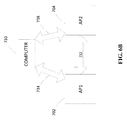
- FIG. 6B is a block diagram of another example system in which a computer, alone or in combination with access point devices, coordinates transmissions to reduce interference between a first wireless network and a second wireless network, according to an embodiment.
- FIG. 7 is block diagram of an example apparatus configured to reduce interference in wireless communications involving two or more overlapping basic service sets (OBSSs), according to an embodiment.
- OBSSs overlapping basic service sets
- a first communication device e.g., an access point in a first wireless network coordinates transmissions within the first network with transmissions within a second wireless network so as to avoid interference with the second wireless network.
- FIG. 1 is a block diagram of an example WLAN 10 in which devices such as an access point (AP) 14 and client devices 25 exchange information using Orthogonal Frequency-Division Multiplexing (OFDM) techniques in a multiple input, multiple output (MIMO) mode, according to an embodiment.
- the AP 14 includes a host processor 15 coupled to a network interface 16 .
- the network interface 16 includes a medium access control (MAC) processing unit 18 and a physical layer processing unit 20 .
- the PHY processing unit 20 includes a plurality of transceivers 21 , and the transceivers are coupled to N antennas 24 , where N is a suitable positive integer.
- the AP 14 has the same number of transceivers 21 as antennas 24 , but in other embodiments, the AP 14 may include a different number of transceivers 21 than antennas 24 (e.g., there may be more antennas than transceivers and antenna switching techniques may be utilized). In FIG. 1 , three transceivers 21 and three antennas 24 are illustrated, but in other embodiments, the AP 14 may include different suitable numbers of transceivers 21 and antennas 24 (e.g., 1, 2, 4, 5, 6, 8, etc.).
- the MAC processing unit 18 and the PHY processing unit 20 may be configured to operate according to a communication protocol generally similar to the IEEE 802.11n Standard and/or the IEEE 802.11ac Standard, for example. In other embodiments, other suitable communications protocols may be utilized.
- the network interface device 16 (e.g., the MAC processing unit 18 and/or the PHY processing unit 20 ) may be configured to perform access point coordination procedures with client devices 25 , as described below, in some embodiments.
- a client device 25 - 1 may include a host processor 26 coupled to a network interface 27 .
- the network interface 27 may include a MAC processing unit 28 and a PHY processing unit 29 .
- the PHY processing unit 29 includes a plurality of transceivers 30 , and the transceivers are coupled to a plurality of antennas 34 .
- the client device 25 - 1 may include different numbers of transceivers 30 and antennas 34 , in other embodiments.
- three transceivers 30 and three antennas 34 are illustrated in FIG.
- the client device 25 - 1 may include different suitable numbers (e.g., 1, 2, 4, 5, etc.) of transceivers 30 and antennas 34 in other embodiments.
- the transceiver(s) 30 is/are configured to transmit generated data streams via the antenna(s) 34 .
- the transceiver(s) 30 is/are configured to receive data streams via the antenna(s) 34 .
- one or both of the client devices 25 - 2 and 25 - 3 have a structure the same as or similar to the client device 25 - 1 .
- the client devices 25 structured like the client device 25 - 1 have the same or a different number of transceivers and antennas.
- the client device 25 - 2 may have only two transceivers and two antennas, according to an embodiment.
- the WLAN 10 may also include one or more legacy client devices 25 - 4 that operate according to a legacy communications protocol.
- FIG. 2 is a block diagram of an environment 200 in which multiple APs are operating, each AP corresponding to a different WLAN, according to an embodiment.
- Each WLAN is a Basic Service Set (BSS) that includes an AP and one or more client devices such as client devices 25 discussed above with reference to FIG. 1 , according to an embodiment.
- BSS Basic Service Set
- BSS 1 There are seven regions labeled BSS 1 , BSS 2 . . . BSS 7 illustrated in FIG. 2 .
- Each region represents a BSS whose transmissions may overlap or interfere with transmissions of one or more other BSSs.
- BSS 1 has a service that partially overlaps with each of BSS 2 , BSS 3 . . . BSS 7 .
- a data packet transmitted from an AP or one of the client devices in BSS 1 may be received by an AP or one of the client devices in one or more of BSS 1 , BSS 2 . . . BSS 7 .
- BSS 1 has a large overlap with BSS 2 but a much smaller overlap, for example, with BSS 7 .
- BSS 7 a transmission from BSS 1 is more likely to be received by one or more devices in BSS 2 than it is to be received by one or more devices in BSS 7 , for example.
- FIG. 2 illustrating seven BSSs having overlapping service areas is presented merely for illustration. Other embodiments may include greater or fewer numbers of BSSs having overlapping service regions.
- BSS 1 While the service area of BSS 1 overlaps with six other BSS service areas (i.e., with BSS 2 , BSS 3 . . . BSS 7 ), some BSSs, such as BSS 2 , may overlap with service areas of fewer BSSs.
- the service area for BSS 2 has overlap, for example, only with the service areas of BSS 1 , BSS 3 , and BSS 6 .
- transmissions in BSS 2 may be received in BSS 1 , BSS 3 , and BSS 6
- transmission in BSS 2 are less likely to be received, for example, in BSS 3 , BSS 4 , and BSS 7 , for example, where there is little or no overlap of the respective service areas.
- the plurality of BSS service areas illustrated in FIG. 2 represents an example of a densely deployed WLAN.
- a system may experience co-channel interference (CCI).
- CCI co-channel interference
- OBSS overlapping BSS service areas
- OBSS may experience CCI if two or more overlapping BSS service areas are utilizing a common frequency channel.
- FIG. 2 illustrates an example OBSS 200 in which CCI may occur between two or more overlapping BSS service areas that operate using a common frequency channel.
- a system operating using the 2.4 GHz band may have only three frequency channels available, according to an embodiment.
- the three available channels in such an embodiment will be referred to by the numbers 1, 2, 3 in the following discussion.
- service areas labeled BSS 1 , BSS 6 , and BSS 7 each may operate according to channel 1 , as indicated.
- Service areas labeled BSS 2 and BSS 4 each may operate according to channel 2 , as indicated.
- service areas labeled BSS 3 and BSS 5 may operate according to channel 3 , as indicated.
- the greatest likelihood for CCI may occur between BSS 1 , BSS 6 , and BSS 7 . This may occur because the service region of BSS 1 overlaps with the service regions both BSS 6 and with BSS 7 , and because each of regions BSS 1 , BSS 6 , and BSS 7 operate using channel 1 .
- a transmission in BSS 1 may cause CCI in BSS 6 and BSS 7 , for example.
- a transmission in BSS 6 may cause CCI in BSS 1 and BSS 7
- a transmission in BSS 7 may cause CCI in BSS 1 and BSS 6 .
- transmissions in BSS 1 are less likely to cause CCI with regions BSS 2 and BSS 4 because, although the service areas of BSS 1 , BSS 2 , and BSS 4 overlap, the three BSSs operate using different channels, with BSS 1 operating according to channel 1 , while BSS 2 and BSS 4 operate according to channel 2 .
- transmissions in BSS 1 are less likely to cause CCI with BSS 3 and BSS 5 because, although the service areas of BSS 1 , BSS 3 , and BSS 5 overlap, they operate using different channels, with BSS 1 operating according to channel 1 , while BSS 3 and BSS 5 operate utilizing channel 3 .
- transmissions in BSS 6 may cause CCI with BSS 1 because BSS 6 and BSS 1 overlap and both operate according to channel 1 .
- transmissions in BSS 6 are less likely to cause CCI in BSS 2 and BSS 3 because, although BSS 6 overlaps with both BSS 2 and BSS 3 , BSS 6 operates according to channel 1 , while BSS 2 and BSS 3 operate according to channel 3 .
- BSS 6 shares the same operating channel with BSS 7 (i.e., channel 1 )
- BSS 7 i.e., channel 1
- a collision involving a unicast packet occurs, transmission is blocked for a certain period of time.
- a unicast packet from BSS 1 may be accidentally received by the AP or a client device in BSS 6 .
- the reception of the unicast packet transmitted from BSS 1 and received by BSS 6 causes delays in BSS 6 .
- the unicast packet received by BSS 6 may trigger Clear Channel Assessment (CCA) procedures to be performed by devices in BSS 6 .
- CCA Clear Channel Assessment
- processing may continue at the MAC level.
- the mismatch of the MAC address may be revealed. At such point it may be discovered CCI has occurred.
- the processing of the incorrectly received packet causes CCA to continue to hold the media until the end of the packet has been processed.
- transmission in BSS 6 may be incorrectly blocked due to the processing of an incorrectly received unicast packet from BSS 1 , for example.
- Similar delays may occur due to CCI involving broadcast packets.
- a broadcast packet transmitted by BSS 1 may be incorrectly received in BSS 6 due to CCI between BSS 1 and BSS 6 if the CCI between BSS 1 and BSS 6 is sufficiently strong.
- processing of management frames may continue at the MAC level until the end of the packet is reached.
- the device processing the broadcast packet may set a Network Allocation Vector (NAV) that blocks its own transmission for a specified time duration.
- NAV Network Allocation Vector
- the present disclosure provides embodiments that enable coordination of traffic in OBSS so that CCI collisions can be avoided or at least reduced in number as compared to prior art OBSSs.
- mechanisms may be provided so that an AP in a first BSS can detect interference from one or more neighboring BSSs.
- BSS 1 may be provided with systems and methods for detecting the presence of CCI caused by BSS 6 and BSS 7 .
- the AP in BSS 1 or a client device in BSS 1 may receive a transmission of a unicast or broadcast packet from, say, BSS 6 .
- the packet that was received by a device in BSS 1 contains information regarding the sender (i.e., a device in BSS 6 ) as well as information regarding the intended receiver (i.e., one or more devices in BSS 6 ).
- the strength of the signal representing the packet received from BSS 6 may be determined.
- the station may report receipt of the packet and information regarding a level of interference to BSS 1 caused by the packet, such as a strength of the signal related to the packet.
- the AP in BSS 1 may determine the degree to which CCI caused by BSS 6 represents a source of interference in BSS 1 . For example, CCI from BSS 6 may be determined to be sufficiently weak as to not represent a significant source of interference in BSS 1 . As such, CCI from BSS 6 may be ignored.
- CCI from BSS 6 may represent a significant source of interference in BSS 1 , for example due to collisions of data packets, as discussed above.
- the AP in a given BSS may determine the presence of significant CCI from a plurality of neighboring BSS.
- BSS 1 may determine that two or more neighboring BSS (e.g., BSS 6 and BSS 7 ) represent a significant source of interference due to CCI.
- CCI may result between BSS 6 and BSS 1 as well as between BSS 7 and BSS 1 .
- a method to avoid collisions e.g., packet collisions between BSS 6 and BSS 1 , and packet collisions between BSS 7 and BSS 1
- a method to avoid collisions e.g., packet collisions between BSS 6 and BSS 1 , and packet collisions between BSS 7 and BSS 1
- traffic in the respective networks can be coordinated so that CCI can be minimized.
- determining that interference from another BSS is significant comprises determining that a metric associated with interference from the other BSS meets a threshold level. For example, in an embodiment, determining that interference from another BSS is significant comprises determining that a signal level of a packet from the other BSS meets a threshold level. As another example, in an embodiment, determining that interference from another BSS is significant comprises determining that a rate of collisions with packets from the other BSS meets a threshold level. In other embodiments, other suitable metrics are utilized.
- FIG. 3 illustrates a flow diagram of an example method 300 for reducing interference in wireless communications involving two or more OBSS, according to an embodiment.
- the method 300 may be implemented by one or more communication devices in (or communicatively coupled to) the example wireless local area network 10 described with reference to FIG. 1 .
- the method 300 may be implemented by the AP 14 , e.g., by one of or any suitable combination of two or more of (i) the host processor 15 , the network interface 16 , the MAC processing device 18 , and/or the PHY processing device 20 , according to various embodiments.
- the method may be implemented at least partially (e.g., alone or in combination with the AP 14 ) by the client device 25 - 1 , e.g., by one of or any suitable combination of two or more of (i) the host processor 26 , the network interface 27 , the MAC processing device 28 , and/or the PHY processing device 29 , according to various embodiments.
- the method 300 is discussed with reference to local area network 10 ( FIG. 1 ) and/or with OBSS 200 ( FIG. 2 ) merely for explanatory purposes. In other embodiments, the method 300 may be implemented by another suitable apparatus and/or system, and/or in the context of another suitable OBSS.
- a communication device e.g., a first AP of a first wireless network determines a presence of interference between the first wireless network and a second wireless network. This may be accomplished, for example, based on receipt of a transmission from the second wireless network by the AP of the first BSS or by a client device in the first BSS. For example, a station (STA) within the first network may receive a transmission from one or more devices in the second network.
- STA station
- the receiving STA within the first network may then send a report to the AP of the first network informing the AP of the origin of the interfering signal as well as a measured metric associated with a level of interference caused by the interfering signal (e.g., signal strength, rate of collisions, etc.), according to an embodiment.
- the receiving STA may determine whether interference caused by the signal is significant (e.g., according to techniques described above, in some embodiments), and report reception of the signal to the first AP only when the STA determines that the interference was significant.
- the first AP may directly receive the interfering signal and determine a level of interference caused by the interfering signal.
- determining that interference from the second network is significant comprises determining that a metric associated with interference from the second network meets a threshold level. For example, in an embodiment, determining that interference from the second network is significant comprises determining that a signal level of a packet from the second network meets a threshold level. As another example, in an embodiment, determining that interference from the second network is significant comprises determining that a rate of collisions with packets from the second network meets a threshold level. In other embodiments, other suitable metrics are utilized.
- the first AP determines whether the interference is significant. For example, in some embodiments, the first AP compares a metric indicating a level of interference to a threshold. As another example, in some embodiments, the first AP determines that interference is significant when the first AP receives a report of interference from a STA in the first wireless network, and the first AP assumes that the STA only reports such interference when the STA determines the interference is significant. In some embodiments, a STA in the first wireless network determines whether the interference is significant, and informs the STA that the interference is significant.
- a communication device e.g., the first AP of the first network may coordinate transmissions in the first wireless network with transmissions in the second wireless network to reduce interference between the first wireless network and the second wireless network.
- coordinating transmissions in the first wireless network with transmissions in the second wireless network may include determining first time slots in which transmissions in the first wireless network are to occur and in which transmissions in the second wireless network are not to occur, according to an embodiment.
- coordinating transmissions in the first wireless network with transmissions in the second wireless network may include determining second time slots in which transmissions in the second wireless network are to occur and in which transmissions in the first wireless network are not to occur, according to an embodiment.
- Block 308 may include the first AP communicating with a second AP of the second network to coordinate transmissions, in some embodiments.
- Block 308 may include the first AP communicating with a second AP of the second network to exchange information regarding first time slots as discussed above, in some embodiments.
- Block 308 may include the first AP communicating with a second AP of the second network to exchange information regarding second time slots as discussed above, in some embodiments.
- the AP of the first network may schedule transmissions in the first wireless network, based on the coordinating of block 308 in order to reduce interference between the first wireless network and the second wireless network. For example, in some embodiments, transmissions within the first network may be scheduled to occur during the first time slots discussed above. Similarly, in some embodiments, transmissions within the first network may be scheduled to not occur during the second time slots. In some embodiments, transmissions within the first network may be scheduled to not occur during the second time slots, but the first network may operate normally according to a communication protocol during the first time slots.
- FIG. 4 illustrates an example TxOP 400 that may be used to schedule transmission within the first wireless network, during times when there are no transmissions in the second network, according to an embodiment.
- a first STA 402 (labeled Tx) may send a request-to-send (RTS) packet 404 to a receiving STA 406 (labeled Rx).
- the receiving STA 406 may send a clear-to-send (CTS) packet 408 back to the sending STA 402 indicating that the receiving STA 406 is clear to receive data 410 from the sending STA 402 .
- CTS clear-to-send
- data 408 may be transmitted from the transmitting STA 402 to the receiving STA 406 .
- data is transmitted between the transmitting STA 402 and the receiving STA 406 .
- All other devices within the BSS remain inactive, not transmitting or receiving, during the time duration set by the NAV 412 .
- These other STAs within the BSS by also receiving the RTS/CTS packets 404 / 408 , are instructed to remain inactive during the time duration set by the NAV 412 .
- the first AP in the first wireless network may establish transmit opportunity (TxOP) periods corresponding to the second time slots to prevent STAs in the first wireless network from transmitting during the second time slots. That is, traffic in the first network may be suppressed during the second time slots during which traffic in the second network is scheduled to occur (e.g., the second time slots are reserved for the second wireless network). In some embodiments, suppression of traffic in the first network may be accomplished using reservations mechanisms the same as or similar to request-to-send (RTS) and clear-to-send-to-self (CTS-to-self) mechanisms defined in the current IEEE 802.11 Standard.
- RTS request-to-send
- CTS-to-self clear-to-send-to-self
- the first AP of the first BSS may transmit an RTS to reserve a time period corresponding to a second time slot in which the first BSS is to remain quiet.
- the RTS will cause each STA in the first BSS to set a network allocation vector (NAV) and refrain from transmitting during a time period corresponding to the NAV.
- NAV network allocation vector
- the first AP also refrains from the transmitting during the time period corresponding to the NAV, and thus the first BSS remains quiet during the time period corresponding to the NAV.
- FIG. 4 is a timing diagram of a “virtual” RTS/CTS exchange 400 that a first communication device (e.g., an AP) of a first wireless network may utilize to suppress transmissions in the first network, according to an embodiment.
- first communication device 402 (labeled Tx) transmits a “virtual RTS” packet 404 to a particular second communication device 406 (labeled Rx) in the first wireless network.
- the virtual RTS 404 may include an indication of a time period corresponding to a reservation of a wireless medium associated with the first communication network.
- the second communication device 406 transmits a clear-to-send (CTS) packet 408 . Additionally, the second communication device 406 sets a NAV 410 corresponding to the time period indicated by the RTS 404 . The second communication device 406 then refrains from transmitting during the time period indicated by the NAV 410 . Additionally, the first communication device 402 sets a NAV corresponding to the time period indicated by the RTS 404 , and then refrains from transmitting during the time period indicated by the NAV.
- CTS clear-to-send
- the virtual RTS packet 404 is a regular RTS packet utilized during normal communications in the first wireless network (e.g., when the first wireless network is not refraining from transmissions for purposes of mitigating interference between the first wireless network and the second wireless network).
- the virtual RTS packet 404 may conform to a legacy communication protocol (e.g., one or more of the IEEE 802.11a, the IEEE 802.11b, the IEEE 802.11g, the IEEE 802.11n, and the IEEE 802.11ac standards) at least to the extent that legacy devices (e.g., configured to operate according to the legacy communication protocol) in the first wireless network can decode the RTS packet 404 and set their NAV accordingly.
- a legacy communication protocol e.g., one or more of the IEEE 802.11a, the IEEE 802.11b, the IEEE 802.11g, the IEEE 802.11n, and the IEEE 802.11ac standards
- the virtual RTS packet 404 includes information to distinguish the virtual RTS packet 404 from regular RTS packets.
- the virtual RTS packet 404 includes a field (e.g., one or more bits) set to a particular value to distinguish the RTS packet 404 from regular RTS packets.
- client devices e.g., 25 - 1 . . . 25 - 3
- client devices may recognize the “virtual” RTS/CTS packets, due to the presence of the information.
- “virtual” RTS/CTS packets with additional distinguishing information are configured such that legacy devices will simply interpret such “virtual” RTS/CTS packets as “ordinary” RTS/CTS packets.
- FIG. 5 is a timing diagram of a “virtual” CTS-to-self transmission 600 that a first communication device (e.g., an AP) of a first wireless network may utilize to suppress transmissions in the first network, according to an embodiment.
- first communication device 602 (labeled Tx) transmits a “virtual CTS-to-self” packet 604 to a particular one or more second communication device in the first wireless network or broadcasts the packet 604 .
- the virtual CTS-to-self 604 may include an indication of a time period corresponding to a reservation of a wireless medium associated with the first communication network.
- the first communication device 602 sets a NAV 608 corresponding to the time period indicated by the CTS-to-self 604 , and then refrains from transmitting during the time period indicated by the NAV 608 .
- other communication devices in the first wireless network set respective NAVs corresponding to the time period indicated by the CTS-to-self 604 , and then refrain from transmitting during the time period corresponding to the NAVs.
- the virtual CTS-to-self 604 is a regular CTS-to-packet utilized during normal communications in the first wireless network (e.g., when the first wireless network is not refraining from transmissions for purposes of mitigating interference between the first wireless network and the second wireless network).
- the virtual CTS-to-self packet 604 may conform to a legacy communication protocol (e.g., one or more of the IEEE 802.11a, the IEEE 802.11b, the IEEE 802.11g, the IEEE 802.11n, and the IEEE 802.11ac standards) at least to the extent that legacy devices (e.g., configured to operate according to the legacy communication protocol) in the first wireless network can decode the CTS-to-self packet 604 and set their NAV accordingly.
- a legacy communication protocol e.g., one or more of the IEEE 802.11a, the IEEE 802.11b, the IEEE 802.11g, the IEEE 802.11n, and the IEEE 802.11ac standards
- the virtual CTS-to-self packet 604 includes information to distinguish the virtual CTS-to-self packet 604 from regular CTS-to-self packets.
- the virtual CTS-to-self packets 604 include a field (e.g., one or more bits) set to a particular value to distinguish the CTS-to-self packet 604 from regular CTS-to-self packets.
- Client devices e.g., 25 - 1 . . . 25 - 3
- “virtual” CTS-to-self packets with additional distinguishing information are configured such that legacy devices will simply interpret such “virtual” CTS-to-self packets as “ordinary” CTS-to-self packets.
- a first network may coordinate its traffic so as to not interfere with traffic in a second network. This may be implemented through coordination between an AP of a first network and an AP of a second network.
- FIG. 6A is a block diagram of an environment in which multiple APs are operating, each AP corresponding to a different WLAN, according to an embodiment.
- two APs 702 , 704 have overlapping respective service areas.
- AP 1 702 has a structure the same or similar to the AP 14 ( FIG. 1 )
- AP 2 704 has a structure the same or similar to the AP 14 ( FIG. 1 ).
- AP 1 702 and AP 2 704 coordinate as discussed above.
- AP 1 702 and AP 2 704 are communicatively coupled via a communication link 112 , and coordinating such as described above includes exchanging information via the communication link 112 .
- the communication link 112 is a WLAN link on a channel utilized by both the first communication network and the second communication network.
- the communication link 112 is a WLAN link on a channel that is not utilized by either the first communication network or the second communication network.
- the communication link 112 is separate from the first wireless network and the second wireless network.
- the communication line 112 corresponds to a wireless network separate from the first communication network and the second communication network.
- the wireless network corresponding to the link 112 operates according to a different communication protocol (e.g., long term evolution (LTE), IEEE 802.11af, IEEE 802.11ah, etc.) than utilized by either the first communication network or the second communication network.
- LTE long term evolution
- IEEE 802.11af IEEE 802.11ah
- the link 112 corresponds to a wired communication link or network.
- a computer separate from AP 1 702 and AP 2 704 coordinates transmissions in the first wireless network and the second wireless network for the purpose of mitigating interference between the first wireless network and the second wireless network.
- a computer 730 is communicatively coupled to AP 1 702 via a communication link 734 .
- the host computer 730 is communicatively coupled to AP 2 704 via a communication link 738 .
- the computer 730 coordinates transmissions as discussed above.
- one or both of the communication links 734 , 738 are WLAN links on a channel utilized by both the first communication network and the second communication network. In another embodiment, one or both of the communication links 734 , 738 are WLAN links on a channel that is not utilized by either the first communication network or the second communication network. In an embodiment, one or both of the communication links 734 , 738 are separate from the first wireless network and the second wireless network. For example, in an embodiment, one or both of the communication links 734 , 738 correspond to a wireless network separate from the first communication network and the second communication network.
- one or more wireless networks corresponding to one or both of the communication links 734 , 738 operate according to one or more different communication protocols (e.g., LTE, IEEE 802.11af, IEEE 802.11ah, etc.) than utilized by either the first communication network or the second communication network.
- one or both of the communication links 734 , 738 correspond to a wired communication link or network.
- one computer 730 e.g., a communication device
- any suitable number of computers may be used to coordinate transmissions for multiple APs.
- the computer 730 may be embodied in a communication device configured to communicatively couple with AP 1 702 and AP 2 704 .
- the computer 730 may include or be coupled to one or more network interface devices configured to communicate with AP 1 702 and AP 2 704 .
- the computer 730 may comprise a processor that executes machine readable instructions stored in a memory device of or coupled to the computer 730 .
- the method 300 may be implemented at least partially (e.g., alone or in combination with the AP 14 ) by the computer 730 , according to an embodiment.
- a first AP or computer may determine respective presences and/or levels of interference between the first wireless network and a plurality of other wireless networks, including determining a presence of interference between the first wireless network and the second wireless network, and determining with which of the other wireless networks transmissions in the first wireless network should be coordinated.
- an AP of the first network or computer may determine with which of the other wireless networks transmissions in the first wireless network should be coordinated based on respective interference levels (or interference strengths) between the first network and the other wireless networks.
- FIG. 7 is a block diagram of an example apparatus 800 comprising configured to perform a method for reducing interference in wireless communications involving two or more OBSS, according to an embodiment.
- the apparatus 800 is included in the AP 14 ( FIG. 1 ), according to an embodiment.
- the apparatus 800 is included in one of or any suitable combination of two or more of the host 15 , the network interface 16 , the MAC processing device 18 , and/or the PHY processing device 20 .
- the apparatus 800 is implemented in the computer 730 ( FIG. 6B ).
- the apparatus 800 is implemented using one or more integrated circuit devices, according to some embodiments.
- the apparatus 800 is implemented in an application specific integrated circuit (ASIC), in a programmable logic device (PLD), etc.
- ASIC application specific integrated circuit
- PLD programmable logic device
- the apparatus 800 is implemented in a processor configured to execute machine readable instructions stored in a non-transitory memory device.
- the apparatus 800 include an interference detection module 802 , a coordination module 804 , and a scheduling module 806 .
- the interference detection module 802 may be configured to determine, a presence of interference between a first wireless network and a second wireless network.
- the coordination module 804 may be configured to coordinate transmissions in the first wireless network with transmissions in the second wireless network to reduce interference between the first wireless network and the second wireless network.
- the scheduling module 806 may be configured to schedule transmissions in the first wireless network, based on the coordinating to reduce interference between the first wireless network and the second wireless network.
- methods, apparatus, systems described herein are utilized with wireless networks that communicate using channels below 10 MHz. In some embodiments, methods, apparatus, systems described herein are utilized with wireless networks that communicate using channels below 10 MHz and above 1 MHz. In some embodiments, methods, apparatus, systems described herein are utilized with wireless local area networks (WLANs) that operate according to one of or any suitable combination of two or more of the IEEE 802.11a Standard, the IEEE 802.11b Standard, the IEEE 802.11g Standard, the IEEE 802.11n Standard, and/or the IEEE 802.11ac Standard.
- WLANs wireless local area networks
- methods, apparatus, systems described herein are utilized with WLANs that operate according to a suitable WLAN communication protocol other than the IEEE 802.11a Standard, the IEEE 802.11b Standard, the IEEE 802.11g Standard, the IEEE 802.11n Standard, and the IEEE 802.11ac Standard.
- a non-transitory computer readable storage medium having computer program instructions stored thereon is provided.
- the computer program instructions are such that, when executed by one or more processors, cause the one or more processors to perform a method for reducing interference in wireless communications systems as described above with reference to FIGS. 1-7 .
- a method for reducing interference in wireless communications including: determining, by a communication device of or communicatively coupled to a first wireless network, a presence of interference between the first wireless network and a second wireless network; coordinating, with the first communication device, transmissions in the first wireless network with transmissions in the second wireless network to reduce interference between the first wireless network and the second wireless network; and scheduling, at a first access point, transmissions in the first wireless network, based on the coordinating to reduce interference between the first wireless network and the second wireless network.
- the method includes one of or any suitable combination of two or more of the following elements.
- Coordinating transmissions in the first wireless network with transmissions in the second wireless network includes: determining first time slots in which transmissions in the first wireless network are to occur; and determining second time slots in which transmissions in the first wireless network are not to occur.
- Scheduling transmissions in the first wireless network includes establishing, with the first access point, transmit opportunity (TxOP) periods corresponding to the second time slots to prevent stations in the first wireless network from transmitting during the second time slots.
- TxOP transmit opportunity
- Establishing TxOP periods includes transmitting, with the first access point one or more clear-to-send-to-self (CTS-to-self) packets and/or one or more request-to-send (RTS) packets to establish the TxOP periods.
- CTS-to-self clear-to-send-to-self
- RTS request-to-send
- the method further includes generating the one or more RTS packets to include one or more bits to distinguish the one or more RTS packets from RTS packets not used for reducing interference with another wireless network.
- the method further includes receiving, at the first access point, one or more clear-to-send (CTS) packets responsive to the one or more RTS packets, wherein the one or more CTS packets include one or more bits to distinguish the one or more CTS packets from CTS packets transmitted in response to RTS packets not used for preventing interference with another wireless network.
- CTS clear-to-send
- Determining the presence of interference includes receiving, at the first access point, a report indicating interference with the second wireless network, the report received from a station in the first wireless network.
- the report includes an identifier of the second wireless network.
- determining the presence of interference includes detecting, at the first access point, transmissions in the second wireless network.
- the method further includes: determining, at the first access point, respective presences of interference between the first wireless network and a plurality of other wireless networks, including determining the presence of interference between the first wireless network and the second wireless network; and determining with which of the other wireless networks transmissions in the first wireless network should be coordinated.
- Determining with which of the other wireless networks transmissions in the first wireless network should be coordinated is based on respective interference levels between the first wireless network and the other wireless networks.
- Determining with which of the other wireless networks transmissions in the first wireless network should be coordinated is performed at least partially at the first access point.
- Determining with which of the other wireless networks transmissions in the first wireless network should be coordinated is performed jointly at the first access point and access points of the other wireless networks.
- an apparatus including one or more integrated circuit devices configured to: determine a presence of interference between a first wireless network and a second wireless network, coordinate transmissions in the first wireless network with transmissions in the second wireless network to reduce interference between the first wireless network and the second wireless network, and schedule transmissions in the first wireless network, based on the coordinating to reduce interference between the first wireless network and the second wireless network.
- the apparatus comprises one of or any suitable combination of two or more of the following elements.
- the one or more integrated circuit devices are further configured to determine first time slots in which transmissions in the first wireless network are to occur, and determine second time slots in which transmissions in the first wireless network are not to occur.
- the one or more integrated circuit devices are further configured to establish transmit opportunity (TxOP) periods corresponding to the second time slots to prevent stations in the first wireless network from transmitting during the second time slots.
- TxOP transmit opportunity
- the one or more integrated circuit devices are further configured to establish TxOP periods by causing an access point of the first wireless network one or more clear-to-send-to-self (CTS-to-self) packets and/or one or more request-to-send (RTS) packets to establish the TxOP periods.
- CTS-to-self clear-to-send-to-self
- RTS request-to-send
- the one or more integrated circuit devices are further configured to generate the one or more RTS packets to include one or more bits to distinguish the one or more RTS packets from RTS packets not used for reducing interference with another wireless network.
- the one or more integrated circuit devices are further configured to process one or more clear-to-send (CTS) packets responsive to the one or more RTS packets, and wherein the one or more CTS packets include one or more bits to distinguish the one or more CTS packets from CTS packets transmitted in response to RTS packets not used for preventing interference with another wireless network.
- CTS clear-to-send
- a non-transitory computer readable storage medium having computer program instructions stored thereon that, when executed by one or more processors, cause the one or more processors to: determine a presence of interference between a first wireless network and a second wireless network; coordinate transmissions in the first wireless network with transmissions in the second wireless network to reduce interference between the first wireless network and the second wireless network; and schedule transmissions in the first wireless network, based on the coordinating to reduce interference between the first wireless network and the second wireless network.
- At least some of the various blocks, operations, and techniques described above may be implemented utilizing hardware, a processor executing firmware instructions, a processor executing software instructions, or any combination thereof.
- the software or firmware instructions may be stored in any tangible, non-transitory computer readable memory such as a magnetic disk, an optical disk, a magnetic tape, a RAM, a ROM, a flash memory, etc.
- the hardware may comprise one or more of discrete components, an integrated circuit, an application-specific integrated circuit (ASIC), a programmable logic device (PLD), etc.
- ASIC application-specific integrated circuit
- PLD programmable logic device
Abstract
Description
Claims (12)
Priority Applications (1)
| Application Number | Priority Date | Filing Date | Title |
|---|---|---|---|
| US14/488,240 US9629169B2 (en) | 2013-09-16 | 2014-09-16 | Access point coordination for traffic control in wireless networks |
Applications Claiming Priority (2)
| Application Number | Priority Date | Filing Date | Title |
|---|---|---|---|
| US201361878309P | 2013-09-16 | 2013-09-16 | |
| US14/488,240 US9629169B2 (en) | 2013-09-16 | 2014-09-16 | Access point coordination for traffic control in wireless networks |
Publications (2)
| Publication Number | Publication Date |
|---|---|
| US20150078353A1 US20150078353A1 (en) | 2015-03-19 |
| US9629169B2 true US9629169B2 (en) | 2017-04-18 |
Family
ID=51660628
Family Applications (1)
| Application Number | Title | Priority Date | Filing Date |
|---|---|---|---|
| US14/488,240 Active 2034-12-12 US9629169B2 (en) | 2013-09-16 | 2014-09-16 | Access point coordination for traffic control in wireless networks |
Country Status (2)
| Country | Link |
|---|---|
| US (1) | US9629169B2 (en) |
| WO (1) | WO2015039116A2 (en) |
Cited By (2)
| Publication number | Priority date | Publication date | Assignee | Title |
|---|---|---|---|---|
| US20180213567A1 (en) * | 2015-07-24 | 2018-07-26 | Zte Corporation | Transmission control method and apparatus for avoiding data collision |
| US11095391B2 (en) | 2018-12-19 | 2021-08-17 | Nxp Usa, Inc. | Secure WiFi communication |
Families Citing this family (11)
| Publication number | Priority date | Publication date | Assignee | Title |
|---|---|---|---|---|
| CN105451337B (en) * | 2014-08-01 | 2019-01-04 | 展讯通信(上海)有限公司 | The control method and device of clear channel assessment (CCA) thresholding |
| EP3178275B1 (en) * | 2014-08-05 | 2019-03-27 | Telefonaktiebolaget LM Ericsson (publ) | Method and apparatus for determining threshold for interference coordination |
| EP3211953B1 (en) * | 2014-12-03 | 2019-04-03 | Huawei Technologies Co., Ltd. | Method and communication device for using spectrum resource for communication |
| CN105792224B (en) * | 2014-12-26 | 2019-06-04 | 上海无线通信研究中心 | A kind of inter-network interference coordination approach |
| WO2016118056A1 (en) * | 2015-01-21 | 2016-07-28 | Telefonaktiebolaget Lm Ericsson (Publ) | Wireless local area network access points |
| EP3614634B1 (en) | 2015-11-12 | 2022-10-12 | Telefonaktiebolaget LM Ericsson (publ) | Channel estimation evaluation in mimo systems |
| US10531506B2 (en) * | 2016-01-15 | 2020-01-07 | Avago Technologies International Sales Pte. Limited | Collaborative operation of software defined radios |
| US10455455B2 (en) * | 2016-11-04 | 2019-10-22 | Qualcomm Incorporated | Techniques for reservation preamble for prioritized medium contention in a new radio shared spectrum communication system |
| US11245501B2 (en) | 2018-09-04 | 2022-02-08 | Qualcomm Incorporated | Multi-access point scheduling in wireless local area networks |
| US11330600B2 (en) * | 2020-01-24 | 2022-05-10 | Cisco Technology, Inc. | Cohesive resource management for wireless networks |
| US11445500B2 (en) * | 2020-05-06 | 2022-09-13 | Cisco Technology, Inc. | Time-sensitive networking in high density networks |
Citations (52)
| Publication number | Priority date | Publication date | Assignee | Title |
|---|---|---|---|---|
| US6590884B1 (en) | 1999-01-07 | 2003-07-08 | Texas Instruments Incorporated | Method and apparatus providing spatial diversity within an indoor network |
| US20050058151A1 (en) * | 2003-06-30 | 2005-03-17 | Chihsiang Yeh | Method of interference management for interference/collision avoidance and spatial reuse enhancement |
| US20060067426A1 (en) | 2004-09-28 | 2006-03-30 | Maltsev Alexander A | Multicarrier transmitter and methods for generating multicarrier communication signals with power amplifier predistortion and linearization |
| US20070217455A1 (en) * | 2004-04-16 | 2007-09-20 | Martin Haeusler | Method and Device for Interference Mitigation Using Redundant Transmission in Separate Ism Bands |
| US20070232235A1 (en) | 2006-03-30 | 2007-10-04 | Guoqing Li | Coordinated transmissions in wireless networks |
| US20080144493A1 (en) * | 2004-06-30 | 2008-06-19 | Chi-Hsiang Yeh | Method of interference management for interference/collision prevention/avoidance and spatial reuse enhancement |
| US20080240208A1 (en) | 2007-03-26 | 2008-10-02 | Cisco Technology Inc. | Adaptive Switching Techniques for Hybrid Automatic Repeat Request Systems |
| US20090080579A1 (en) | 2007-09-25 | 2009-03-26 | Samsung Electronics Co., Ltd. | Receiving apparatus and method |
| WO2009084904A2 (en) | 2007-12-31 | 2009-07-09 | Lg Electronics Inc. | Method for reducing inter-cell interference |
| US20090196163A1 (en) | 2006-07-05 | 2009-08-06 | Koninklijke Philips Electronics N.V. | Bandwidth asymmetric communication system based on ofdm and tdma |
| US20090233554A1 (en) * | 2008-03-11 | 2009-09-17 | Carlos Cordeiro | Mitigation of internetwork interference |
| US7599332B2 (en) | 2004-04-05 | 2009-10-06 | Qualcomm Incorporated | Modified preamble structure for IEEE 802.11a extensions to allow for coexistence and interoperability between 802.11a devices and higher data rate, MIMO or otherwise extended devices |
| US20090296649A1 (en) * | 2008-05-27 | 2009-12-03 | Kyocera Corporation | Base station and wireless communication method |
| WO2009152852A1 (en) | 2008-06-18 | 2009-12-23 | Telefonaktiebolaget L M Ericsson (Publ) | Intercell interference reduction |
| US20100040033A1 (en) * | 2008-08-14 | 2010-02-18 | Texas Instruments Incorporated | Reverse direction grant (rdg) for wireless network technologies subject to coexistence interference |
| US20100046358A1 (en) | 2008-08-19 | 2010-02-25 | Qualcomm Incorporated | Training sequences for very high throughput wireless communication |
| US20100091675A1 (en) | 2008-10-10 | 2010-04-15 | Sony Corporation | Wireless communication system, wireless communication device and wireless communication method, and computer program |
| US20100118837A1 (en) * | 2008-11-11 | 2010-05-13 | Qualcomm Incorporated | Using synchronization frames for mesh networking with piconets |
| US7742390B2 (en) | 2005-08-23 | 2010-06-22 | Agere Systems Inc. | Method and apparatus for improved long preamble formats in a multiple antenna communication system |
| US20100233963A1 (en) * | 2009-03-12 | 2010-09-16 | Ntt Docomo, Inc. | Controller and method for use in radio station in radio communication system |
| US20100278065A1 (en) * | 2009-04-29 | 2010-11-04 | Texas Instruments Inc. | Traffic Load Estimation for Access Point Functionality Enabled Mobile Devices |
| US20100309834A1 (en) | 2009-06-05 | 2010-12-09 | Broadcom Corporation | Channel characterization and training within multiple user, multiple access, and/or mimo wireless communications |
| US20110002219A1 (en) | 2009-06-05 | 2011-01-06 | Broadcom Corporation | Group identification and definition within multiple user, multiple access, and/or mimo wireless communications |
| US20110110250A1 (en) * | 2008-04-02 | 2011-05-12 | Lg Electronics Inc. | Method of allocating channel time, method of determining compatible links, and apparatus for processing data |
| US20110158115A1 (en) * | 2009-04-01 | 2011-06-30 | Texas Instruments Inc. | Power Efficiency and Packet Delivery Ratio Through Micro Rate Control at Access Point Functionality Enabled Devices |
| US20110188391A1 (en) * | 2010-02-04 | 2011-08-04 | Texas Instruments Incorporated | INTERRELATED WiFi AND USB PROTOCOLS AND OTHER APPLICATION FRAMEWORK PROCESSES, CIRCUITS AND SYSTEMS |
| US20110223867A1 (en) | 2010-03-10 | 2011-09-15 | Chan-Byoung Chae | Methods for reducing interference in communication systems |
| US20110268217A1 (en) | 2010-04-29 | 2011-11-03 | Eden Rock Communications, Llc | Systems and methods for coordinating the scheduling of beamformed data to reduce interference |
| US20110280226A1 (en) * | 2008-12-23 | 2011-11-17 | Tomas Lennvall | Multi-Network Manager, Method And System |
| US20110294514A1 (en) * | 2010-05-28 | 2011-12-01 | Kabushiki Kaisha Toshiba | Radio resource management in femtocells |
| US20110305156A1 (en) | 2010-06-11 | 2011-12-15 | Yong Liu | Method and Apparatus for Determining Channel Bandwidth |
| US20120028672A1 (en) * | 2010-07-30 | 2012-02-02 | Tao Chen | Apparatus and Method for Transmitter Power Control for Device-to-Device Communications in a Communication System |
| US20120034874A1 (en) | 2010-08-06 | 2012-02-09 | Simon Yiu | Apparatuses and/or methods of interference mitigation and/or rate improvement via uncoordinated beamforming in heterogeneous networks |
| US20120039196A1 (en) | 2010-08-10 | 2012-02-16 | Hongyuan Zhang | Sub-band feedback for beamforming on downlink multiple user mimo configurations |
| US20120087265A1 (en) | 2009-04-27 | 2012-04-12 | Hitachi, Ltd. | Wireless communication system, integrated base station, and terminal |
| US20120113918A1 (en) * | 2010-11-05 | 2012-05-10 | Interdigital Patent Holdings, Inc. | Silent period method and apparatus for dynamic spectrum management |
| US20120149414A1 (en) * | 2010-12-10 | 2012-06-14 | Qualcomm Incorporated | Interference management between multiple networks |
| US8270909B2 (en) | 2009-03-31 | 2012-09-18 | Marvell World Trade Ltd. | Sounding and steering protocols for wireless communications |
| US20120263068A1 (en) * | 2010-01-07 | 2012-10-18 | Ntt Docomo, Inc. | Mobile terminal apparatus, radio base station apparatus and radio communication method |
| WO2012156574A1 (en) | 2011-05-13 | 2012-11-22 | Nokia Corporation | Interference management in wireless network |
| WO2013001968A1 (en) | 2011-06-29 | 2013-01-03 | Sharp Kabushiki Kaisha | Channel state information feedback method and user equipment |
| US20130035128A1 (en) * | 2011-08-02 | 2013-02-07 | Cisco Technology, Inc. | Narrowband Interference Avoidance for Dynamic Channel Assignment |
| US20130053078A1 (en) | 2011-08-25 | 2013-02-28 | Qualcomm Incorporated | Backhaul enhancements for cooperative multi-point (comp) operations |
| US20130155931A1 (en) * | 2011-12-15 | 2013-06-20 | Broadcom Corporation | Time domain coexistence of rf signals |
| US8619907B2 (en) | 2004-06-10 | 2013-12-31 | Agere Systems, LLC | Method and apparatus for preamble training in a multiple antenna communication system |
| US8724720B2 (en) | 2009-07-29 | 2014-05-13 | Marvell World Trade Ltd. | Methods and apparatus for WLAN transmission |
| US20140233416A1 (en) * | 2007-11-27 | 2014-08-21 | Qualcomm Incorporated | Interference management in a wireless communication system using frequency selective transmission |
| US20140241240A1 (en) | 2013-02-28 | 2014-08-28 | Cisco Technology, Inc. | Distributed Processing Distributed-Input Distributed-Output (DIDO) Wireless Communication |
| US20140256341A1 (en) * | 2013-03-06 | 2014-09-11 | Interdigital Patent Holdings, Inc. | Interference management and interference alignment in wireless networks |
| US20140302884A1 (en) | 2011-08-18 | 2014-10-09 | Agency For Science, Technology And Research | Method of transmitting data between a plurality of base stations and a plurality of mobile stations |
| US20140334473A1 (en) | 2013-04-10 | 2014-11-13 | Marvell World Trade Ltd. | Method and apparatus for mitigating interference in a wireless network through use of transmit beamforming |
| US9325540B2 (en) | 2013-04-10 | 2016-04-26 | Marvell World Trade Ltd. | Method and apparatus for mitigating interference in a wireless network through use of transmit beamforming |
-
2014
- 2014-09-16 US US14/488,240 patent/US9629169B2/en active Active
- 2014-09-16 WO PCT/US2014/055900 patent/WO2015039116A2/en active Application Filing
Patent Citations (53)
| Publication number | Priority date | Publication date | Assignee | Title |
|---|---|---|---|---|
| US6590884B1 (en) | 1999-01-07 | 2003-07-08 | Texas Instruments Incorporated | Method and apparatus providing spatial diversity within an indoor network |
| US20050058151A1 (en) * | 2003-06-30 | 2005-03-17 | Chihsiang Yeh | Method of interference management for interference/collision avoidance and spatial reuse enhancement |
| US7599332B2 (en) | 2004-04-05 | 2009-10-06 | Qualcomm Incorporated | Modified preamble structure for IEEE 802.11a extensions to allow for coexistence and interoperability between 802.11a devices and higher data rate, MIMO or otherwise extended devices |
| US20070217455A1 (en) * | 2004-04-16 | 2007-09-20 | Martin Haeusler | Method and Device for Interference Mitigation Using Redundant Transmission in Separate Ism Bands |
| US8619907B2 (en) | 2004-06-10 | 2013-12-31 | Agere Systems, LLC | Method and apparatus for preamble training in a multiple antenna communication system |
| US20080144493A1 (en) * | 2004-06-30 | 2008-06-19 | Chi-Hsiang Yeh | Method of interference management for interference/collision prevention/avoidance and spatial reuse enhancement |
| US20060067426A1 (en) | 2004-09-28 | 2006-03-30 | Maltsev Alexander A | Multicarrier transmitter and methods for generating multicarrier communication signals with power amplifier predistortion and linearization |
| US7742390B2 (en) | 2005-08-23 | 2010-06-22 | Agere Systems Inc. | Method and apparatus for improved long preamble formats in a multiple antenna communication system |
| US20070232235A1 (en) | 2006-03-30 | 2007-10-04 | Guoqing Li | Coordinated transmissions in wireless networks |
| US20090196163A1 (en) | 2006-07-05 | 2009-08-06 | Koninklijke Philips Electronics N.V. | Bandwidth asymmetric communication system based on ofdm and tdma |
| US20080240208A1 (en) | 2007-03-26 | 2008-10-02 | Cisco Technology Inc. | Adaptive Switching Techniques for Hybrid Automatic Repeat Request Systems |
| US20090080579A1 (en) | 2007-09-25 | 2009-03-26 | Samsung Electronics Co., Ltd. | Receiving apparatus and method |
| US20140233416A1 (en) * | 2007-11-27 | 2014-08-21 | Qualcomm Incorporated | Interference management in a wireless communication system using frequency selective transmission |
| WO2009084904A2 (en) | 2007-12-31 | 2009-07-09 | Lg Electronics Inc. | Method for reducing inter-cell interference |
| US20090233554A1 (en) * | 2008-03-11 | 2009-09-17 | Carlos Cordeiro | Mitigation of internetwork interference |
| US20110110250A1 (en) * | 2008-04-02 | 2011-05-12 | Lg Electronics Inc. | Method of allocating channel time, method of determining compatible links, and apparatus for processing data |
| US20090296649A1 (en) * | 2008-05-27 | 2009-12-03 | Kyocera Corporation | Base station and wireless communication method |
| WO2009152852A1 (en) | 2008-06-18 | 2009-12-23 | Telefonaktiebolaget L M Ericsson (Publ) | Intercell interference reduction |
| US20100040033A1 (en) * | 2008-08-14 | 2010-02-18 | Texas Instruments Incorporated | Reverse direction grant (rdg) for wireless network technologies subject to coexistence interference |
| US20100046358A1 (en) | 2008-08-19 | 2010-02-25 | Qualcomm Incorporated | Training sequences for very high throughput wireless communication |
| US20100091675A1 (en) | 2008-10-10 | 2010-04-15 | Sony Corporation | Wireless communication system, wireless communication device and wireless communication method, and computer program |
| US20100118837A1 (en) * | 2008-11-11 | 2010-05-13 | Qualcomm Incorporated | Using synchronization frames for mesh networking with piconets |
| US20110280226A1 (en) * | 2008-12-23 | 2011-11-17 | Tomas Lennvall | Multi-Network Manager, Method And System |
| US20100233963A1 (en) * | 2009-03-12 | 2010-09-16 | Ntt Docomo, Inc. | Controller and method for use in radio station in radio communication system |
| US8270909B2 (en) | 2009-03-31 | 2012-09-18 | Marvell World Trade Ltd. | Sounding and steering protocols for wireless communications |
| US20110158115A1 (en) * | 2009-04-01 | 2011-06-30 | Texas Instruments Inc. | Power Efficiency and Packet Delivery Ratio Through Micro Rate Control at Access Point Functionality Enabled Devices |
| US20120087265A1 (en) | 2009-04-27 | 2012-04-12 | Hitachi, Ltd. | Wireless communication system, integrated base station, and terminal |
| US20100278065A1 (en) * | 2009-04-29 | 2010-11-04 | Texas Instruments Inc. | Traffic Load Estimation for Access Point Functionality Enabled Mobile Devices |
| US20110002219A1 (en) | 2009-06-05 | 2011-01-06 | Broadcom Corporation | Group identification and definition within multiple user, multiple access, and/or mimo wireless communications |
| US20100309834A1 (en) | 2009-06-05 | 2010-12-09 | Broadcom Corporation | Channel characterization and training within multiple user, multiple access, and/or mimo wireless communications |
| US8526351B2 (en) | 2009-06-05 | 2013-09-03 | Broadcom Corporation | Channel characterization and training within multiple user, multiple access, and/or MIMO wireless communications |
| US8724720B2 (en) | 2009-07-29 | 2014-05-13 | Marvell World Trade Ltd. | Methods and apparatus for WLAN transmission |
| US20120263068A1 (en) * | 2010-01-07 | 2012-10-18 | Ntt Docomo, Inc. | Mobile terminal apparatus, radio base station apparatus and radio communication method |
| US20110188391A1 (en) * | 2010-02-04 | 2011-08-04 | Texas Instruments Incorporated | INTERRELATED WiFi AND USB PROTOCOLS AND OTHER APPLICATION FRAMEWORK PROCESSES, CIRCUITS AND SYSTEMS |
| US20110223867A1 (en) | 2010-03-10 | 2011-09-15 | Chan-Byoung Chae | Methods for reducing interference in communication systems |
| US20110268217A1 (en) | 2010-04-29 | 2011-11-03 | Eden Rock Communications, Llc | Systems and methods for coordinating the scheduling of beamformed data to reduce interference |
| US20110294514A1 (en) * | 2010-05-28 | 2011-12-01 | Kabushiki Kaisha Toshiba | Radio resource management in femtocells |
| US20110305156A1 (en) | 2010-06-11 | 2011-12-15 | Yong Liu | Method and Apparatus for Determining Channel Bandwidth |
| US20120028672A1 (en) * | 2010-07-30 | 2012-02-02 | Tao Chen | Apparatus and Method for Transmitter Power Control for Device-to-Device Communications in a Communication System |
| US20120034874A1 (en) | 2010-08-06 | 2012-02-09 | Simon Yiu | Apparatuses and/or methods of interference mitigation and/or rate improvement via uncoordinated beamforming in heterogeneous networks |
| US20120039196A1 (en) | 2010-08-10 | 2012-02-16 | Hongyuan Zhang | Sub-band feedback for beamforming on downlink multiple user mimo configurations |
| US20120113918A1 (en) * | 2010-11-05 | 2012-05-10 | Interdigital Patent Holdings, Inc. | Silent period method and apparatus for dynamic spectrum management |
| US20120149414A1 (en) * | 2010-12-10 | 2012-06-14 | Qualcomm Incorporated | Interference management between multiple networks |
| WO2012156574A1 (en) | 2011-05-13 | 2012-11-22 | Nokia Corporation | Interference management in wireless network |
| WO2013001968A1 (en) | 2011-06-29 | 2013-01-03 | Sharp Kabushiki Kaisha | Channel state information feedback method and user equipment |
| US20130035128A1 (en) * | 2011-08-02 | 2013-02-07 | Cisco Technology, Inc. | Narrowband Interference Avoidance for Dynamic Channel Assignment |
| US20140302884A1 (en) | 2011-08-18 | 2014-10-09 | Agency For Science, Technology And Research | Method of transmitting data between a plurality of base stations and a plurality of mobile stations |
| US20130053078A1 (en) | 2011-08-25 | 2013-02-28 | Qualcomm Incorporated | Backhaul enhancements for cooperative multi-point (comp) operations |
| US20130155931A1 (en) * | 2011-12-15 | 2013-06-20 | Broadcom Corporation | Time domain coexistence of rf signals |
| US20140241240A1 (en) | 2013-02-28 | 2014-08-28 | Cisco Technology, Inc. | Distributed Processing Distributed-Input Distributed-Output (DIDO) Wireless Communication |
| US20140256341A1 (en) * | 2013-03-06 | 2014-09-11 | Interdigital Patent Holdings, Inc. | Interference management and interference alignment in wireless networks |
| US20140334473A1 (en) | 2013-04-10 | 2014-11-13 | Marvell World Trade Ltd. | Method and apparatus for mitigating interference in a wireless network through use of transmit beamforming |
| US9325540B2 (en) | 2013-04-10 | 2016-04-26 | Marvell World Trade Ltd. | Method and apparatus for mitigating interference in a wireless network through use of transmit beamforming |
Non-Patent Citations (52)
Cited By (3)
| Publication number | Priority date | Publication date | Assignee | Title |
|---|---|---|---|---|
| US20180213567A1 (en) * | 2015-07-24 | 2018-07-26 | Zte Corporation | Transmission control method and apparatus for avoiding data collision |
| US10624129B2 (en) * | 2015-07-24 | 2020-04-14 | Zte Corporation | Transmission control method and apparatus for avoiding data collision |
| US11095391B2 (en) | 2018-12-19 | 2021-08-17 | Nxp Usa, Inc. | Secure WiFi communication |
Also Published As
| Publication number | Publication date |
|---|---|
| WO2015039116A2 (en) | 2015-03-19 |
| WO2015039116A3 (en) | 2015-05-07 |
| US20150078353A1 (en) | 2015-03-19 |
Similar Documents
| Publication | Publication Date | Title |
|---|---|---|
| US9629169B2 (en) | Access point coordination for traffic control in wireless networks | |
| JP7416834B2 (en) | Wireless communication method for simultaneous data communication and wireless communication terminal using the same | |
| US10624131B2 (en) | Channel access for simultaneous uplink transmissions by multiple communication devices | |
| US10314066B2 (en) | Techniques for protecting communications in wireless local area networks | |
| EP3139671B1 (en) | Spatial reuse parameters for opportunistic adaptive tpc and cca | |
| US10681732B2 (en) | Method and apparatus for collision detection in wider bandwidth operation | |
| CN105766031B (en) | Method and apparatus for transmitting uplink frame in wireless LAN | |
| CN112637967B (en) | Wireless communication terminal and wireless communication method for idle channel allocation | |
| CN110958716B (en) | Wireless communication method for clear channel assessment and wireless communication terminal using the same | |
| US8451771B2 (en) | Medium reservation techniques for multi-user transmissions | |
| EP2919547B1 (en) | Method and apparatus to coordinate simultaneous transmission in overlapping wireless networks | |
| JP6356253B2 (en) | Method and apparatus for transmitting frames in wireless LAN | |
| US9794790B2 (en) | Wireless device, method, and computer readable media for spatial reuse for device-to-device links | |
| US20180376486A1 (en) | Wireless communication method for uplink multiple-user transmission schedule and wireless communication terminal using the method | |
| US9088991B2 (en) | WLAN transmit modes and coexistence | |
| WO2011099791A2 (en) | Channel access method and apparatus in wireless local area network system | |
| US20160360549A1 (en) | A station, an access point and methods therein for handling transmissions in a wireless communications network | |
| US20160353485A1 (en) | Managing medium access for wireless devices | |
| EP3427532B1 (en) | Methods for reducing interference in a wireless communications network | |
| EP2932756B1 (en) | Method for dynamically adjusting channel bandwidth in wireless communications systems | |
| CN110366869B (en) | Interference mitigation for narrowband devices in a wideband environment | |
| WO2016191967A1 (en) | Channel access method and station |
Legal Events
| Date | Code | Title | Description |
|---|---|---|---|
| AS | Assignment |
Owner name: MARVELL INTERNATIONAL LTD., BERMUDA Free format text: ASSIGNMENT OF ASSIGNORS INTEREST;ASSIGNOR:MARVELL SEMICONDUCTOR, INC.;REEL/FRAME:041445/0403 Effective date: 20170216 Owner name: MARVELL SEMICONDUCTOR, INC., CALIFORNIA Free format text: ASSIGNMENT OF ASSIGNORS INTEREST;ASSIGNORS:ZHANG, HONGYUAN;SUN, YAKUN;LOU, HUI-LING;SIGNING DATES FROM 20140901 TO 20140910;REEL/FRAME:041445/0343 Owner name: MARVELL WORLD TRADE LTD., BARBADOS Free format text: ASSIGNMENT OF ASSIGNORS INTEREST;ASSIGNOR:MARVELL INTERNATIONAL LTD.;REEL/FRAME:041445/0588 Effective date: 20170224 Owner name: MARVELL INTERNATIONAL LTD., BERMUDA Free format text: LICENSE;ASSIGNOR:MARVELL WORLD TRADE LTD.;REEL/FRAME:041446/0077 Effective date: 20170301 |
|
| STCF | Information on status: patent grant |
Free format text: PATENTED CASE |
|
| AS | Assignment |
Owner name: MARVELL INTERNATIONAL LTD., BERMUDA Free format text: ASSIGNMENT OF ASSIGNORS INTEREST;ASSIGNOR:MARVELL WORLD TRADE LTD.;REEL/FRAME:051778/0537 Effective date: 20191231 |
|
| AS | Assignment |
Owner name: CAVIUM INTERNATIONAL, CAYMAN ISLANDS Free format text: ASSIGNMENT OF ASSIGNORS INTEREST;ASSIGNOR:MARVELL INTERNATIONAL LTD.;REEL/FRAME:052918/0001 Effective date: 20191231 |
|
| AS | Assignment |
Owner name: MARVELL ASIA PTE, LTD., SINGAPORE Free format text: ASSIGNMENT OF ASSIGNORS INTEREST;ASSIGNOR:CAVIUM INTERNATIONAL;REEL/FRAME:053475/0001 Effective date: 20191231 |
|
| MAFP | Maintenance fee payment |
Free format text: PAYMENT OF MAINTENANCE FEE, 4TH YEAR, LARGE ENTITY (ORIGINAL EVENT CODE: M1551); ENTITY STATUS OF PATENT OWNER: LARGE ENTITY Year of fee payment: 4 |