US9561184B2 - Methods and systems for multi-stage drying of plasma - Google Patents
Methods and systems for multi-stage drying of plasma Download PDFInfo
- Publication number
- US9561184B2 US9561184B2 US14/670,127 US201514670127A US9561184B2 US 9561184 B2 US9561184 B2 US 9561184B2 US 201514670127 A US201514670127 A US 201514670127A US 9561184 B2 US9561184 B2 US 9561184B2
- Authority
- US
- United States
- Prior art keywords
- moisture level
- dried plasma
- collection bag
- plasma
- drying
- Prior art date
- Legal status (The legal status is an assumption and is not a legal conclusion. Google has not performed a legal analysis and makes no representation as to the accuracy of the status listed.)
- Active
Links
Images


Classifications
-
- A—HUMAN NECESSITIES
- A61—MEDICAL OR VETERINARY SCIENCE; HYGIENE
- A61K—PREPARATIONS FOR MEDICAL, DENTAL OR TOILETRY PURPOSES
- A61K9/00—Medicinal preparations characterised by special physical form
- A61K9/14—Particulate form, e.g. powders, Processes for size reducing of pure drugs or the resulting products, Pure drug nanoparticles
- A61K9/16—Agglomerates; Granulates; Microbeadlets ; Microspheres; Pellets; Solid products obtained by spray drying, spray freeze drying, spray congealing,(multiple) emulsion solvent evaporation or extraction
- A61K9/1682—Processes
- A61K9/1688—Processes resulting in pure drug agglomerate optionally containing up to 5% of excipient
-
- A—HUMAN NECESSITIES
- A61—MEDICAL OR VETERINARY SCIENCE; HYGIENE
- A61K—PREPARATIONS FOR MEDICAL, DENTAL OR TOILETRY PURPOSES
- A61K35/00—Medicinal preparations containing materials or reaction products thereof with undetermined constitution
- A61K35/12—Materials from mammals; Compositions comprising non-specified tissues or cells; Compositions comprising non-embryonic stem cells; Genetically modified cells
- A61K35/14—Blood; Artificial blood
- A61K35/16—Blood plasma; Blood serum
-
- A—HUMAN NECESSITIES
- A61—MEDICAL OR VETERINARY SCIENCE; HYGIENE
- A61K—PREPARATIONS FOR MEDICAL, DENTAL OR TOILETRY PURPOSES
- A61K9/00—Medicinal preparations characterised by special physical form
- A61K9/14—Particulate form, e.g. powders, Processes for size reducing of pure drugs or the resulting products, Pure drug nanoparticles
- A61K9/16—Agglomerates; Granulates; Microbeadlets ; Microspheres; Pellets; Solid products obtained by spray drying, spray freeze drying, spray congealing,(multiple) emulsion solvent evaporation or extraction
- A61K9/1605—Excipients; Inactive ingredients
- A61K9/1617—Organic compounds, e.g. phospholipids, fats
-
- A—HUMAN NECESSITIES
- A61—MEDICAL OR VETERINARY SCIENCE; HYGIENE
- A61K—PREPARATIONS FOR MEDICAL, DENTAL OR TOILETRY PURPOSES
- A61K9/00—Medicinal preparations characterised by special physical form
- A61K9/14—Particulate form, e.g. powders, Processes for size reducing of pure drugs or the resulting products, Pure drug nanoparticles
- A61K9/16—Agglomerates; Granulates; Microbeadlets ; Microspheres; Pellets; Solid products obtained by spray drying, spray freeze drying, spray congealing,(multiple) emulsion solvent evaporation or extraction
- A61K9/1682—Processes
-
- B—PERFORMING OPERATIONS; TRANSPORTING
- B01—PHYSICAL OR CHEMICAL PROCESSES OR APPARATUS IN GENERAL
- B01J—CHEMICAL OR PHYSICAL PROCESSES, e.g. CATALYSIS OR COLLOID CHEMISTRY; THEIR RELEVANT APPARATUS
- B01J19/00—Chemical, physical or physico-chemical processes in general; Their relevant apparatus
- B01J19/06—Solidifying liquids
-
- F—MECHANICAL ENGINEERING; LIGHTING; HEATING; WEAPONS; BLASTING
- F26—DRYING
- F26B—DRYING SOLID MATERIALS OR OBJECTS BY REMOVING LIQUID THEREFROM
- F26B3/00—Drying solid materials or objects by processes involving the application of heat
- F26B3/02—Drying solid materials or objects by processes involving the application of heat by convection, i.e. heat being conveyed from a heat source to the materials or objects to be dried by a gas or vapour, e.g. air
- F26B3/04—Drying solid materials or objects by processes involving the application of heat by convection, i.e. heat being conveyed from a heat source to the materials or objects to be dried by a gas or vapour, e.g. air the gas or vapour circulating over or surrounding the materials or objects to be dried
-
- F—MECHANICAL ENGINEERING; LIGHTING; HEATING; WEAPONS; BLASTING
- F26—DRYING
- F26B—DRYING SOLID MATERIALS OR OBJECTS BY REMOVING LIQUID THEREFROM
- F26B3/00—Drying solid materials or objects by processes involving the application of heat
- F26B3/02—Drying solid materials or objects by processes involving the application of heat by convection, i.e. heat being conveyed from a heat source to the materials or objects to be dried by a gas or vapour, e.g. air
- F26B3/06—Drying solid materials or objects by processes involving the application of heat by convection, i.e. heat being conveyed from a heat source to the materials or objects to be dried by a gas or vapour, e.g. air the gas or vapour flowing through the materials or objects to be dried
-
- F—MECHANICAL ENGINEERING; LIGHTING; HEATING; WEAPONS; BLASTING
- F26—DRYING
- F26B—DRYING SOLID MATERIALS OR OBJECTS BY REMOVING LIQUID THEREFROM
- F26B3/00—Drying solid materials or objects by processes involving the application of heat
- F26B3/02—Drying solid materials or objects by processes involving the application of heat by convection, i.e. heat being conveyed from a heat source to the materials or objects to be dried by a gas or vapour, e.g. air
- F26B3/10—Drying solid materials or objects by processes involving the application of heat by convection, i.e. heat being conveyed from a heat source to the materials or objects to be dried by a gas or vapour, e.g. air the gas or vapour carrying the materials or objects to be dried with it
- F26B3/12—Drying solid materials or objects by processes involving the application of heat by convection, i.e. heat being conveyed from a heat source to the materials or objects to be dried by a gas or vapour, e.g. air the gas or vapour carrying the materials or objects to be dried with it in the form of a spray, i.e. sprayed or dispersed emulsions or suspensions
-
- F—MECHANICAL ENGINEERING; LIGHTING; HEATING; WEAPONS; BLASTING
- F26—DRYING
- F26B—DRYING SOLID MATERIALS OR OBJECTS BY REMOVING LIQUID THEREFROM
- F26B5/00—Drying solid materials or objects by processes not involving the application of heat
- F26B5/04—Drying solid materials or objects by processes not involving the application of heat by evaporation or sublimation of moisture under reduced pressure, e.g. in a vacuum
-
- B—PERFORMING OPERATIONS; TRANSPORTING
- B01—PHYSICAL OR CHEMICAL PROCESSES OR APPARATUS IN GENERAL
- B01J—CHEMICAL OR PHYSICAL PROCESSES, e.g. CATALYSIS OR COLLOID CHEMISTRY; THEIR RELEVANT APPARATUS
- B01J2219/00—Chemical, physical or physico-chemical processes in general; Their relevant apparatus
- B01J2219/00049—Controlling or regulating processes
- B01J2219/00177—Controlling or regulating processes controlling the pH
-
- B—PERFORMING OPERATIONS; TRANSPORTING
- B65—CONVEYING; PACKING; STORING; HANDLING THIN OR FILAMENTARY MATERIAL
- B65D—CONTAINERS FOR STORAGE OR TRANSPORT OF ARTICLES OR MATERIALS, e.g. BAGS, BARRELS, BOTTLES, BOXES, CANS, CARTONS, CRATES, DRUMS, JARS, TANKS, HOPPERS, FORWARDING CONTAINERS; ACCESSORIES, CLOSURES, OR FITTINGS THEREFOR; PACKAGING ELEMENTS; PACKAGES
- B65D51/00—Closures not otherwise provided for
- B65D51/24—Closures not otherwise provided for combined or co-operating with auxiliary devices for non-closing purposes
- B65D51/28—Closures not otherwise provided for combined or co-operating with auxiliary devices for non-closing purposes with auxiliary containers for additional articles or materials
- B65D51/30—Closures not otherwise provided for combined or co-operating with auxiliary devices for non-closing purposes with auxiliary containers for additional articles or materials for desiccators
-
- B—PERFORMING OPERATIONS; TRANSPORTING
- B65—CONVEYING; PACKING; STORING; HANDLING THIN OR FILAMENTARY MATERIAL
- B65D—CONTAINERS FOR STORAGE OR TRANSPORT OF ARTICLES OR MATERIALS, e.g. BAGS, BARRELS, BOTTLES, BOXES, CANS, CARTONS, CRATES, DRUMS, JARS, TANKS, HOPPERS, FORWARDING CONTAINERS; ACCESSORIES, CLOSURES, OR FITTINGS THEREFOR; PACKAGING ELEMENTS; PACKAGES
- B65D81/00—Containers, packaging elements, or packages, for contents presenting particular transport or storage problems, or adapted to be used for non-packaging purposes after removal of contents
- B65D81/24—Adaptations for preventing deterioration or decay of contents; Applications to the container or packaging material of food preservatives, fungicides, pesticides or animal repellants
- B65D81/26—Adaptations for preventing deterioration or decay of contents; Applications to the container or packaging material of food preservatives, fungicides, pesticides or animal repellants with provision for draining away, or absorbing, or removing by ventilation, fluids, e.g. exuded by contents; Applications of corrosion inhibitors or desiccators
- B65D81/266—Adaptations for preventing deterioration or decay of contents; Applications to the container or packaging material of food preservatives, fungicides, pesticides or animal repellants with provision for draining away, or absorbing, or removing by ventilation, fluids, e.g. exuded by contents; Applications of corrosion inhibitors or desiccators for absorbing gases, e.g. oxygen absorbers or desiccants
-
- F—MECHANICAL ENGINEERING; LIGHTING; HEATING; WEAPONS; BLASTING
- F26—DRYING
- F26B—DRYING SOLID MATERIALS OR OBJECTS BY REMOVING LIQUID THEREFROM
- F26B5/00—Drying solid materials or objects by processes not involving the application of heat
- F26B5/04—Drying solid materials or objects by processes not involving the application of heat by evaporation or sublimation of moisture under reduced pressure, e.g. in a vacuum
- F26B5/06—Drying solid materials or objects by processes not involving the application of heat by evaporation or sublimation of moisture under reduced pressure, e.g. in a vacuum the process involving freezing
- F26B5/065—Drying solid materials or objects by processes not involving the application of heat by evaporation or sublimation of moisture under reduced pressure, e.g. in a vacuum the process involving freezing the product to be freeze-dried being sprayed, dispersed or pulverised
Definitions
- the present disclosure relates generally to preparing spray dried powders and in particular to two stage drying of blood plasma by controlled desiccation through a membrane such as a wall of a human blood plasma collection bag and de-oxygenation by oxygen scavenging through a membrane such as a wall of a human blood plasma collection bag.
- the inventions have numerous other applications as well.
- blood plasma is a whole blood component in which blood cells and other constituents of whole blood are suspended.
- Blood plasma further contains a mixture of over 700 proteins and additional substances that perform functions necessary for bodily health, including clotting, protein storage, and electrolytic balance, amongst others.
- blood plasma When extracted from whole blood, blood plasma may be employed to replace bodily fluids, antibodies, and clotting factors. Accordingly, blood plasma is extensively used in medical treatments.
- Fresh-Frozen Plasma is obtained through a series of steps involving centrifugation of whole blood to separate plasma and then freezing the collected plasma within less than 8 hours of collecting the whole blood.
- AABB American Association of Blood Banks
- FFP may also be stored for up to 7 years from collection if maintained at a temperature of ⁇ 65° C. or below.
- FFP has a shelf life of only 3 months if stored at temperatures between ⁇ 18° C.
- FFP must be kept in a temperature-controlled environment of ⁇ 18° C. or colder throughout its duration of storage to prevent degradation of certain plasma proteins and maintain its efficacy, which adds to the cost and difficulty of storage and transport.
- FFP must be thawed prior to use, resulting in a delay of 30-80 minutes before it may be used after removal from cold storage.
- a long-standing need and challenge to the blood industry has been to provide safe, reliable and convenient blood products while recovering in processing and preserving the efficacy and safety of the active components of those products in storage (stability) such as human blood plasma proteins known as clotting and coagulation factors (“factors”) and when used in transfusion or as a source a medical treatments.
- the present disclosure provides efficacy preservation in storage and includes the recovery and stability of the clotting factors in the plasma in a manner that does not otherwise harm the plasma or the transfused patient.
- some blood plasma clotting factors may degrade to some extent, due to exposure to shear and other forces or other environmental stresses. Clotting factors may be subject to shearing stresses depending on the spray drying conditions.
- the methods and compositions of the present disclosure recognize that the denaturing effects of shear stress can be reduced or decreased by an enhanced multi-stage drying method using controlled desiccation of the dried plasma and its local environment through a relatively water vapor permeable membrane such as an external wall of a collection bag containing the dried plasma while the desiccant and the collection bag are both separately placed in a storage container such as a relatively water vapor impermeable aluminum sealed outer envelope or pouch.
- the dried plasma may be enhanced by de-oxygenation of the dried plasma and its local environment by an oxygen scavenger through a relatively oxygen permeable membrane such as an exterior wall of a collection bag containing the dried plasma while the collection bag and the oxygen scavenger are both separately placed in a storage container such as a relatively oxygen impermeable aluminum sealed outer envelope or pouch.
- a relatively oxygen permeable membrane such as an exterior wall of a collection bag containing the dried plasma while the collection bag and the oxygen scavenger are both separately placed in a storage container such as a relatively oxygen impermeable aluminum sealed outer envelope or pouch.
- the invention described herein has numerous applications other than moisture control and de-oxygenation of spray dried human blood plasma.
- the present inventions may be used to efficaciously control moisture or oxygen content on lyophilized blood plasma stored in a relatively water vapor or oxygen permeable container such as a plastic bag or bottle.
- the methods and compositions of the present disclosure include recovering amounts of active/undenatured FGN, F V, F VII, F IX and vWF from rehydrated plasma that has undergone the spray drying process.
- vWF also known as von Willibrand factor
- vWF has generally been difficult to recover and has become one indicator for recovery of all factors.
- the other factors are likely to be recovered as well.
- the inventors have discovered that three parameters are consequential to both recovery of human blood plasma factors and their long-term stability (preservation) in storage. These are: 1) the amount of heat that the plasma proteins are exposed to during the drying process is related to the amount recoverable functional plasma protein.
- the moisture content during storage in the local storage environment is related to stability (preservation) of the plasma protein during storage of the plasma protein. Generally, the lower the moisture content the greater the stability (preservation) of the plasma protein during storage.
- the amount of oxidation to which the stored material such a spray dried plasma proteins is exposed in storage is related to stability (preservation) of the plasma proteins in storage. Generally, the less the oxidation in the local storage environment the greater the stability (preservation) of the material such as plasma proteins in storage.
- the inventors have discovered novel ways to control and optimize these critical parameters by developing a two-stage drying process wherein the first drying stage utilizes a controlled spray drying process and the second drying stage uses desiccant in a closed environment. Oxidation is controlled through the use of oxygen scavenger(s) in a closed environment.
- the present invention contemplates a method for spray drying blood plasma, the method comprising: providing a spray drier device having a collection bag; providing blood plasma; spray drying the blood plasma using the spray drier device to produce a dried plasma product recovered in a vapor permeable collection bag, the dried plasma product having a moisture content at a first moisture level, the first moisture level being associated with a substantially non-clumping dried plasma; removing the collection bag from the spray drier device and sealing the collection bag; incubating the sealed collection bag containing dried plasma product in vapor communication with a desiccant material located outside the collection bag having sufficient capacity to lower the moisture content of the dried plasma product from the first moisture level to a second moisture level.
- the present invention further contemplates that plasma factor activity in the dried plasma product is preserved to a greater extent through storage at the second moisture level relative to storage at the first moisture level.
- the present invention further contemplates that the first moisture level is from about 3.5% to about 9.5%.
- the present invention further contemplates that the second moisture level is from about 1.5% to about 6.0%.
- the desiccant material has a mass that is determined as a function of a mass of the dried plasma product, the first moisture level, and the second moisture level.
- the present invention further contemplates that the desiccant material has a mass that is determined as a function of storage temperature.
- the present invention further contemplates that incubating the dried plasma product further comprises storing both the collection bag and the desiccant material within a sealed, substantially vapor impermeable storage pouch.
- the present invention further contemplates storing an oxygen scavenger material outside of the collection bag, wherein the dried plasma maintains vapor communication with the oxygen scavenger material through the collection bag.
- the present invention further contemplates that the collection bag is sealed prior to being removed from the spray drier device.
- the present invention contemplates a method for storing dried plasma product, the method comprising: providing a spray dryer, a vapor-permeable collection bag, a vapor impermeable storage pouch, desiccant and blood plasma; drying the blood plasma in the spray dryer to produce a dried plasma product containing preserved blood plasma clotting factors, the dried plasma product having a moisture content at a first moisture level, wherein the first moisture level is associated with a substantially non-clumping dried plasma product; and collecting the dried plasma product in the vapor permeable collection bag; placing the collection bag containing the dried plasma product in the vapor non-permeable storage pouch containing the desiccant wherein the desiccant is located in the storage pouch outside the collection bag and wherein the desiccant is selected at an amount sufficient to absorb moisture from the dried plasma through the collection bag and to lower the moisture content of the dried plasma product to a desired second moisture level and wherein the desired second moisture level is selected for a combination of stability and preservation of the clotting factors.
- the collection bag comprises: an internal filter bag for containing the dried plasma product and an external bag for containing the filter bag, wherein both the filter bag and the external bag are vapor permeable.
- the present invention further contemplates that the external bag comprises polyvinyl chloride (PVC).
- PVC polyvinyl chloride
- the filter bag comprises 0.2 micron filter material.
- the present invention further contemplates that the first moisture level is from about 3.5% to about 9.5%.
- the present invention further contemplates that the second moisture level is from about 1.5% to about 6.0%.
- the desiccant material has a mass that is a function of a mass of the dried plasma product, the first moisture level, and the second moisture level.
- the present invention further contemplates that the desiccant material has a mass that is a function of storage temperature.
- the present invention further contemplates that drying blood plasma to a first moisture level is performed by a spray drier device.
- the present invention contemplates a kit for incubating a dried plasma product, the kit comprising: a vapor permeable collection bag for collecting the dried plasma product; a desiccant material aliquot for removing moisture from the spray dried plasma product; and a vapor impermeable storage pouch for storing the vapor permeable collection bag and the desiccant material aliquot during processing and storage.
- the present invention further contemplates a plasma administration kit, the kit comprising: a vapor permeable collection container containing dried plasma product; a desiccant material for removing moisture from the spray dried plasma product; and a vapor impermeable storage pouch for storing the vapor permeable collection container and the desiccant material during storage.
- kit additionally comprises an oxygen scavenging material stored within the vapor impermeable storage pouch.
- the dried plasma product has a moisture level of about 1.5% to about 6.0%.
- FIG. 1 is a schematic illustration of a spray drier system according to some embodiments.
- FIGS. 2A and 2B are schematic illustrations of a spray drier assembly according to some embodiments.
- FIG. 3 is a schematic illustration of collection chambers or bags according to some embodiments.
- FIGS. 4A-4B are schematic illustrations of collection chambers or bags according to some embodiments.
- FIGS. 5A-5B are schematic illustrations of the storage pouch containing the collection bag, the desiccant and the oxygen scavenger.
- FIGS. 6A-6B are graphs showing the effectiveness of desiccant located between the inner wall of the non-vapor permeable storage pouch and the outer wall of the vapor-permeable collection bag for decreasing the moisture level of the dried plasma of the present invention from a first moisture level to a second moisture level and maintaining the second moisture level.
- FIG. 7 shows graphs showing the effectiveness of desiccant located between the inner wall of the non-vapor permeable storage pouch and the outer wall of the vapor-permeable collection bag for decreasing a first moisture level to a second moisture level and maintaining a second moisture level.
- Embodiments of the present disclosure are directed to systems and methods for spray drying a liquid sample.
- the liquid sample is plasma obtained from a blood donor.
- the disclosed embodiments may be employed to spray dry other mixtures of solid particles in a continuous liquid medium, including, but not limited to, colloids, suspensions, and sols.
- a spray drier system for spray drying a liquid sample such as blood plasma.
- the spray drier system of the present disclosure includes a spray drier device and a spray drier assembly.
- the spray drier device is adapted, in an aspect, to receive flows of an aerosolizing gas, a drying gas, and plasma liquid sample from respective sources, and to couple with the spray drier assembly.
- the aerosolizing gas may be any suitable gas or gas mixture including filtered air or nitrogen.
- the drying gas may be any suitable gas or gas mixture including filtered and/or heated air or nitrogen.
- One or both gases may be moisture reduced by being passed through a drier or desiccant prior to use in the spray drier assembly of the present invention.
- the spray drier device may further transmit the received aerosolizing gas, drying gas, and plasma to the spray drier assembly. Spray drying of the plasma is performed in the spray drier assembly under the control of the spray drier device.
- the spray drier assembly includes a sterile, hermetically sealed enclosure body and a frame to which the enclosure body is attached.
- the frame defines first, second, and third portions of the assembly, separated by respective transition zones.
- a drying gas inlet is provided within the first portion of the assembly, adjacent to a first end of the enclosure body.
- a spray drying head is further attached to the frame within the transition zone between the first and second portions of the assembly. This position also lies within the incipient flow path of the drying gas within the assembly.
- the spray drying head receives flows of an aerosolizing gas and plasma and aerosolizes the plasma with the aerosolizing gas to form aerosolized plasma (e.g., a suspension of liquid droplets in the gas).
- Drying gas additionally passes through the spray drying head to mix with the aerosolized plasma within the second portion of the assembly for drying.
- contact between the aerosolized plasma and the drying gas causes moisture to move from the aerosolized plasma to the drying gas, producing dried plasma and humid drying gas.
- the spray drying head in an embodiment is adapted to direct the flow of drying gas within the drying chamber.
- the spray drying head includes openings separated by fins which receive the flow of drying gas from the drying gas inlet.
- the orientation of the fins allows the drying gas to be directed in selected flow pathways (e.g., helical).
- selected flow pathways e.g., helical.
- the dried plasma and humid drying gas subsequently flow into the third portion of assembly, which houses a collection chamber or collection bag.
- the dried plasma is isolated from the humid drying gas and collected using a filter in the collection chamber or bag.
- the filter in an embodiment is open on one side to receive the flow of humid air and dried plasma and closed on the remaining sides except for an exhaust port.
- the humid drying gas passes through the filter and is exhausted from the spray drier assembly through an exhaust port in the collection bag.
- the filter is adapted to separate the collection chamber into two parts.
- the first part of the collection chamber is contiguous with the drying chamber and receives the flow of humid drying gas and dried plasma.
- the dried plasma is collected in this first part of the collection chamber, while the humid air passes through the filter and is exhausted from the spray drier assembly via an exhaust port in fluid or vapor communication with the second part of the spray drier assembly.
- the collection chamber or bag After collecting the dried plasma in the collection chamber or bag, the collection chamber or bag is separated from the spray drier assembly and hermetically sealed. In this manner, the sealed collection chamber or bag is used to store the dried plasma until use.
- the collection chamber or bag includes a plurality of ports for injection allowing addition of a rehydration solution (e.g., water, buffer) to the collection chamber for reconstitution of the blood plasma and removal of the reconstituted blood plasma for use.
- the collection chamber or bag may be further attached to a sealed vessel containing rehydration fluid for reconstitution or the container of rehydration fluid may be separate.
- the collection bag may further comprise an internal filter bag and an external bag for containing the filter bag, wherein both the filter bag and the external bag are vapor permeable or have vapor permeable sections.
- the flow path necks down to form segments that are automatically sealed and cut by the instrument to separate the collection bag from the remainder of the disposable for product storage.
- the collection bag may be sealed and cut manually.
- the final section of the disposable ends in a docking port similar to the one at the beginning of the disposable. Once the drying process is completed these ports are automatically re-capped by the instrument and the associated disposable sections are discarded. Only the collection bag is retained for product storage
- FIG. 1 schematically illustrates one embodiment of a spray drier system 100 .
- the system 100 includes a spray drier device 102 configured to receive a spray drier assembly 104 .
- a source of plasma 112 , a source of aerosolizing gas 114 , and a source of drying gas 116 are further in fluid or vapor communication with the spray drier assembly 104 .
- a flow of the drying gas 116 A is caused to flow within the body of the assembly 104 by positive or negative pressure.
- a flow of a blood plasma 112 A and a flow of aerosolizing gas 114 A are each caused to flow (either by positive or negative pressure) at selected, respective rates, to a spray drying head 104 A of the assembly 104 .
- the flow of blood plasma 112 A is aerosolized in the spray drier head 104 A and dried in a drying chamber 104 B, producing a dried plasma that is collected and stored for future use in a collection chamber or bag 104 C.
- Humid drying gas 122 including condensed moisture (e.g., waste water) removed from the blood plasma during the drying process is further collected for appropriate disposal via the exhaust port of the collection bag.
- the spray drier device 102 further includes a spray drier computing device 124 , e.g., such as a computer programmed to regulate the spray drying process with minimal operator input.
- the spray drier computing device 124 is adapted to monitor and control a plurality of process parameters of the spray drying operation.
- the spray drier computing device 124 further includes a plurality of user interfaces.
- the spray drier computing device 124 may further communicate with a remote computing device 150 such as a computer programmed to regulate the drying process and record drying data.
- FIGS. 2A and 2B illustrate embodiments of the spray drier assembly 104 in greater detail.
- the spray drier assembly 104 includes a frame 202 .
- An enclosure or body 204 having first and second ends 208 A, 208 B further extends about and encloses the frame 202 .
- the body 204 adopts or approximately adopts the shape of the frame 202 .
- the enclosure 204 may further include a dual layer of film sealed together about the periphery of the frame 202 .
- the frame 202 may define a first portion 206 A, a second portion 206 B, and a third portion 206 C of the assembly 104 .
- the first portion of the assembly i.e., portion 206 A is positioned adjacent the first end 208 A of the body 204 .
- the third portion of the assembly i.e., portion 206 C is positioned adjacent to the second end 208 B of the enclosure 204 .
- the second portion of the assembly, i.e., portion 206 B is interposed between the first and third portions of the assembly, i.e., portions 206 A and 206 C.
- the frame 202 further defines first and second transition zones 210 A, 210 B between the first, second, and third portions of the assembly 206 A, 206 B, 206 C.
- first transition zone 210 A may be positioned between the first and second portions of the assembly 206 A, 206 B and the second transition zone 210 B may be positioned between the second and third portions of the assembly 206 B, 206 C.
- the frame 202 may narrow in width within the transition zones 210 A, or 210 B, as compared to the width of the surrounding assembly. The relatively narrow transition zones 210 A, 210 B help to direct the flow of drying gas 116 A through the assembly 104 .
- the body 204 may include a drying gas inlet 212 , adjacent to the first end 208 A.
- the drying gas inlet 212 may be adapted to couple with the spray drier device 102 to form a hermetic and sterile connection that allows the flow of drying gas 116 A to enter the assembly 104 .
- the drying gas inlet 212 is positioned within the first portion of the assembly 206 A, at about the terminus of the first end of the body 208 A. In this configuration, the flow of drying gas 116 A is received within the assembly 104 in a direction approximately parallel to a long axis 250 of the assembly 104 .
- the body 204 may include a drying gas inlet 212 ′.
- the position of the drying gas inlet 212 ′ is moved with respect to drying gas inlet 212 .
- the drying gas inlet 212 ′ may be positioned within the first portion of the assembly 206 A and spaced a selected distance from the terminus of the first end of the enclosure 208 A.
- the flow of drying gas 116 A may be received within the assembly 104 in a direction that is not parallel to the long axis 250 of the assembly 104 .
- the flow of drying gas 116 A is received within the assembly 104 in a direction that is approximately perpendicular to the long axis 250 of the assembly 104 .
- the spray drier assembly 104 may further include a removable cover 218 .
- the cover 218 may be employed prior to coupling of the spray drier assembly 104 with the spray drier device 102 in order to inhibit contaminants from entering the spray drier assembly.
- the cover 218 may be removed immediately prior to coupling with the spray drier device 102 or frangible and penetrated by the spray drier device 102 during coupling with the spray drier assembly 104 .
- the drying gas 116 A received by the assembly 104 is caused to travel from the first portion 206 A, through the second portion 206 B, to the third portion 206 C, where it is removed from the assembly 104 .
- the drying gas 116 A passes through a first filter 220 A which filters the drying gas 116 A entering the assembly 104 in addition to filtering taking place within the spray drier device 102 between the drying gas source 116 and the drying gas inlet 212 .
- the first filter 220 A is a 0.2 micron filter having a minimum BFE (bacterial filtration efficiency) of 106. The filter 220 A further helps to ensure the cleanliness of the flow of drying gas 116 A.
- the flow of aerosolizing gas 114 A or drying gas 116 A used during primary or (if so used) secondary drying can be supplied by a plurality of heating devices in thermal communication with the spray drier assembly 104 .
- the heating devices may include, but are not limited to, devices that employ energy such as electromagnetic, radiofrequency, radiation, and microwaves for heating.
- the plurality of heating devices may emit electro-magnetic radiation that passes through the walls of the drying chamber 104 B, the collection chamber 104 C, or both for heating the flows of aerosolizing gas 114 A and/or drying gas 116 A therein.
- the flow of drying gas 116 A received by the spray drier assembly 104 may possess a temperature from about 50° C. to about 150° C. and a flow rate of from about 15 CFM to about 35 CFM.
- the flow of aerosolizing gas 116 A can possess a flow rate of from about 5 L/min to about 20 L/min and a temperature from about 15° C. to about 30° C. (e.g., 24° C.).
- the flow of liquid sample 112 A may possess a flow rate of from about 3 ml/min to about 20 ml/min.
- the flow of the aerosolizing gas 114 A, the flow of drying gas 116 A, or both may direct the flow of the dried sample 232 through at least a portion of the spray drier assembly 104 (e.g., the drying chamber, the collection chamber, or both).
- the assembly 104 may further include a spray drying head 104 A, a drying chamber 104 B, and a collection chamber or bag 104 C in fluid or vapor communication with one another.
- the spray drying head 104 A may be mounted to the frame 202 and positioned within the first transition zone 210 A. So positioned, the spray drying head 104 A is also positioned within the flow of drying gas 116 A traveling from the first portion of the assembly 206 A to the second portion of the assembly 206 B.
- the spray drying head 104 A may be further adapted to receive the flow of plasma 112 A and the flow of aerosolizing gas 114 A through respective feed lines 214 , 216 and output aerosolized plasma 230 to the drying chamber 104 B.
- the drying chamber 104 B and collection chamber or bag 104 C may be positioned within the second and third portions of the assembly 206 B, 206 C, respectively.
- the drying chamber 104 B may inflate under the pressure of the flow of drying gas 116 A and provides space for the aerosolized blood plasma 230 and the flow of drying gas 116 A to contact one another.
- moisture is transferred from the aerosolized blood plasma 230 to the drying gas 116 A (i.e., primary drying), where the drying gas 116 A becomes humid drying gas 234 .
- the aerosolized flow of blood plasma 230 and the flow of drying gas 116 A are further separated, within the drying chamber 104 B, into dried plasma 232 and humid drying gas 234 .
- the dried plasma 232 may include dried plasma particles that have diameters of less than or equal to 25 ⁇ m.
- the humid drying gas 234 and dried plasma 232 further proceed into the collection chamber 104 C through an inlet port 222 A of the collection chamber or bag 104 C, positioned within the second transition zone 210 B, connecting the collection chamber or bag 104 C and the drying chamber 104 B.
- the collection chamber 104 includes a second filter 220 B which allows through-passage of the humid drying gas 234 and inhibits through-passage of the dried plasma 232 .
- the humid drying gas 234 passing through the filter 220 B is separated from the dried plasma 232 and exhausted from the collection bag 104 C through an exhaust port 222 B of the collection bag 104 C that forms the second end 208 B of the body 204 .
- a vacuum source e.g., a vacuum pump
- a vacuum source may be in fluid or vapor communication with the exhaust port 222 B of the collection chamber 104 C to force the humid drying gas 234 through exhaust port 222 B.
- the dried plasma 232 is retained in a reservoir 229 of the collection chamber or bag 104 C.
- the collection chamber 104 C is subsequently hermetically sealed at about the inlet and exhaust ports 222 A, 222 B, and detached (e.g., cut) from the spray drier assembly 104 , allowing the collection chamber 104 C to subsequently function as a storage vessel for the dried plasma 232 until use.
- the collection chamber 104 C may be further configured for use in rehydrating the dried plasma 232 .
- the collection chamber 104 C may include a rehydration port 224 , a plurality of spike ports 226 , and a vent port 228 .
- the rehydration port 224 may be used to communicate with a source of rehydration solution, allowing the rehydration solution to come in contact with the dried plasma 232 within the collection chamber 104 C to form reconstituted plasma.
- the reconstituted plasma may be subsequently drawn from the collection chamber 104 C through the spike ports 226 .
- Exhaust port 222 B may be adapted to allow venting of the flow of humid drying gas 234 during secondary drying.
- the vents 702 A, 702 B may allow for gas flow as discussed above and the exhaust port 222 B may be closed.
- the vents 702 A, 702 B may be sealed and the exhaust port 222 B opened.
- the exhaust port 222 B may be further placed in fluid or vapor communication with a vacuum source (e.g., a vacuum pump) for secondary drying.
- a filter e.g. 0.22 ⁇ m or better
- the collection chamber 104 C′ (see, FIG. 4A for an exploded view of the collection chamber) so constructed is illustrated in cross-section in FIG. 4B . It may be observed that the filter member 904 separates the area enclosed by the collection chamber or bag walls 902 A, 902 B into two chambers, 920 A and 920 B. The chamber or bag surround is shown as 906 . The filter support is shown as 910 . The inlet port 222 A of the collection chamber 104 C′ is in fluid or vapor communication with the chamber 920 A. The flow of dried plasma particles 232 and humid drying gas 234 entering the collection chamber 104 C′ flow into the first chamber 920 A.
- Filter member 904 inhibits the dried plasma particles 232 from passing through the first chamber 920 A and into the second chamber 920 B, while the humid drying gas 234 freely passes through the filter 904 into the second chamber 920 B. Accordingly, the dried plasma particles 232 are retained for storage within the first chamber 920 A, while the humid drying gas 234 exits the collection chamber 104 C′ via the exhaust port 222 B.
- Spray dried plasma produced using the spray drying apparatus as described above is preferably dried to a first moisture level of 3.5% to 9.5% (but may be another level, which may be determined empirically).
- This moisture level is referred to herein as the “first moisture level” and is characterized by a substantially “non-clumping” spray dried plasma product.
- the non-clumping product tends to flow freely into the collection bag, as opposed to clumping, sticking and accumulating within the drying chamber or at points prior to entry into the collection bag or sticking to the processing equipment walls or failing to flow to the collection chamber.
- the first moisture level is selected for minimum denaturing and adequate flow properties. Drying to the first moisture level of 3.5% to 9.5% has been determined to optimize recovery of dried blood plasma components such as clotting factors while achieving adequate flow properties.
- a preferred method for determining moisture levels is described in the Exemplification section, below.
- Levels of heat and gas flow during the primary spray drying process contribute to denaturation of blood plasma components.
- Primary spray drying parameters are controlled to minimize denaturation while attaining good, non-clumping flow properties of the spray dried product.
- moisture at the first moisture level can affect long term storage (i.e., preservation, stability) of the plasma proteins.
- the collection bag comes after the drying chamber.
- the dried plasma particles arrive at the collection bag entrained in the drying gas air stream.
- the collection bag filter stops the plasma particles while allowing the drying gas to pass through the filter toward the exhaust port.
- the collection bag is constructed with the flow path defined by the outer films with a filter located within the drying bag.
- the collection bag includes tube ports that are used to introduce the rehydration solution and connect the rehydrated plasma to an infusion set for administration to the patient. These ports are welded between the two films of the bag using a standard tube welding process.
- Exemplary material information for the collection bag and storage pouch are as follows:
- vapor permeable materials can be used for the outer collection bag.
- non-vapor permeable materials can be used if at least a section of the outer collection bag is vapor permeable.
- spray dried plasma produced through first stage spray drying is to be transferred to a distinct vapor permeable container prior to secondary drying, it is not essential that the collection be vapor permeable.
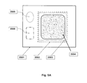
- FIGS. 3 and 4A-4B show an embodiment of the collection bag. Further embodiments of the collection bag of the present invention are shown in FIG. 5 (A & B) (porting omitted).
- FIG. 5A shows a view of a horizontal cross section of a collection bag 2002 within a storage pouch 2001 .
- the collection bag comprises a vapor-permeable filter material 2003 which captures spray dried plasma but allows process air to pass through and out of the spray drier system.
- the collection bag may have a portion of the surface that is vapor-permeable or the complete surface may be vapor-permeable.
- the desiccant is preferably held in a container (e.g., canister, sachet or pouch).
- the desiccant container is located outside the collection bag 2002 and within the storage pouch 2001 .
- the oxygen scavenger is contained in a container outside the collection bag and within the storage pouch.
- FIG. 5B shows a vertical cross section of the collection bag 2002 , desiccant 2005 and oxygen scavenger 2006 , located in the storage pouch 2001 .
- Other features of the storage pouch and collection bag described elsewhere in this specification are not shown here merely to not clutter the figure.
- the collection bag discussed above is, in preferred embodiments, produced from a plastic film.
- a dried blood plasma collection bag produced from PVC when sealed within a substantially vapor impermeable storage pouch together with a desiccant volume within the storage pouch but external to the collection bag, permits the transfer of moisture in the form of vapor through the walls of the collection bag to the desiccant sink. This process is the secondary drying process.
- the gentle withdrawal of moisture from the dried plasma product in this way has been found to decrease the first moisture level to a second moisture level of about 1.5% to 6.0% with little or no further denaturing of the plasma proteins (e.g., clotting factors).
- the starting point with regard to the first moisture level produced by the primary spray dry process may be higher in some collection bags as compared to others.
- the secondary moisture level achieved by the secondary drying process with the desiccant will also have variation with higher secondary moisture levels the result of having higher first moisture levels. Therefore, is rare instances, the secondary moisture level may be higher in some collection bags as compared to the first moisture level in other collection bags.
- dried plasma product which has undergone a primary spray drying cycle is removed from the spray drying apparatus in a sealed, vapor permeable collection bag.
- the sealing process is conducted within the spray drying apparatus, but sealing of the collection bag can take place following removal of the collection bag from the spray drying apparatus.
- the dried plasma product having a first moisture level is removed from the spray dryer and sealed in one of more vapor permeable containers which are then sealed and put in vapor communication with a desiccant material located outside the vapor permeable container, the desiccant material having sufficient capacity to lower the moisture content of the dried plasma product from the first moisture level to a second moisture level.
- the dried plasma with a first moisture level may be in the collection bag or chamber or may be removed to another suitable vapor permeable container.
- the filter bags discussed in the exemplification section, below, are one example of a vapor permeable container that is not a collection bag or collection chamber.
- discussion in this specification with regard to obtaining a second moisture level in a collection bag and collection chamber also refer to obtaining a second moisture level in the vapor permeable container described above. Any discussion in the present patent application related to secondary drying of spray dried plasma in a sealed collection bag is equally applicable to the secondary drying of spray dried plasma in a vapor permeable container generally.
- the sealed collection bag has at least a vapor permeable section and may be completely or nearly completely vapor permeable.
- the sealed collection bag is placed or deposited into a storage pouch.
- the storage pouch is essentially or substantially vapor impermeable.
- Aluminum lined polymer bags are an example of a suitable storage pouch and are discussed in further detail below.
- the desiccant is also placed or deposited within the storage pouch external to the collection bag.
- the desiccant is preferably packaged in vapor permeable containers, pouches or satchels.
- Storage pouches house the collection bag and comprise, internal to the storage pouch and external to the collection bag (i.e., between the inner wall of the storage pouch and the outer wall of the collection bag) one or more desiccants and, optionally, one or more oxygen scavengers.
- the external storage pouches are moisture impermeable or essentially moisture impermeable (i.e., have a very low or moisture transmission rate) and are oxygen impermeable or essentially oxygen impermeable (i.e., have a very low oxygen transmission rate).
- the storage pouches of the present invention preferably have a moisture vapor transmission rate of about 0.035 g/m 2 /day or below but may range from about 0.060 g/m 2 /day to 0.001 g/m 2 /day or below.
- An example of a suitable storage pouch is the ULINE 10 ⁇ 12′′ Dri-Shield Moisture Barrier Bag (Part number S-6498).
- Other suitable storage pouches are known to or can be readily identified by those of skill in the art.
- Secondary drying may be accomplished by any the use of an appropriate amount of desiccant placed either in fluid or vapor communication with the dried plasma outside of the collection chamber or bag but within a storage pouch (outer container) enclosing the collection chamber or bag. So configured, the moisture level of the powder material (i.e., plasma) within the collection chamber or bag may be reduced as the moisture is drawn through a permeable wall of the collection chamber or bag to the desiccant.
- a storage pouch outer container
- embodiments of secondary drying operations discussed herein are designed to complement the primary spray drying processes discussed above, allowing for further reduction in the moisture content of the plasma (i.e., from a first moisture level to a second moisture level) after primary drying is completed, without significantly damaging the plasma proteins.
- the dried plasma stored after undergoing primary and secondary drying is preserved with an improved storage or shelf life remaining suitable for later reconstitution and use.
- Desiccants are used in the secondary drying process to reduce the first moisture level to a secondary moisture level.
- Desiccants are hydroscopic substances that are readily available commercially. Desiccants suitable for use in the present invention include, but are not limited to silica gel, activated charcoal, anhydrous calcium sulfate, calcium chloride, and molecular sieves (typically, microporous, aluminosilicate minerals called zeolites).
- the amount of desiccant required for the second phase drying can be calculated as follows.
- FIGS. 6A and 6B show differences in efficiency of the secondary drying process based on storage temperature. The figures show that lower storage temperatures result in a lower secondary moisture level when the dried plasma at the first moisture level is in vapor communication with the desiccant.
- desiccant amounts suitable for obtaining a desired secondary moisture level at various storage temperatures based on the teachings of this specification.
- the present invention also contemplates the use of oxygen scavengers to reduce the oxygen level in the collection bag.
- the oxygen scavenger is packaged in a canister, satchet or the like, and is put inside the storage pouch and outside of the collection bag.
- Oxygen scavengers are known in the art and are commonly used in the pharmaceutical industry for protecting, for example, pharmaceuticals, nutraceutical and diagnostic products against oxygen degradation and oxidative reactions.
- Oxygen scavengers can be metal-based or polymer-based.
- Metal-based scavengers usually contain ferrous carbonate and a metal halide catalyst and typically require moisture to function.
- One exemplary commercially available oxygen scavenger is produced by Mitsubishi Gas Chemical Co., Inc. (Tokyo, Japan) and is sold under the trade name PharmaKeep®.
- PharmaKeep® is a polymer-based oxygen scavenger with a high oxygen absorption capacity of 20 mL O 2 per gram scavenger.
- the present invention also contemplates a kit.
- the kit of the present invention comprises a vapor permeable collection bag for collecting the dried plasma product, a desiccant material for removing moisture from the spray dried plasma product and a vapor impermeable storage pouch for storing the vapor permeable collection bag and the desiccant material during processing and storage.
- the kit may also comprise instructions for use and suitable packaging for transport to destination locations.
- fluid communication shall be described herein as meaning that substances (gas, vapor, liquid, solutions, sols, collides, suspensions or particulates, for example) can move or pass freely from one location to another such as from one section of the drying device of the present invention to another.
- the movement may be unidirectional or bidirectional, depending on the context described herein.
- the movement may be continuous or intermittent (i.e., intermittent fluid commination).
- the movement may be facilitated by external forces such as, but not limited to, positive and negative pressure or may be the result of diffusion.
- vapor communication shall be described herein a meaning that vapor, gas and constituents of the vapor or gas (e.g., water molecules) can move or pass from one location to another such as from one section of the drying device of the present invention to another.
- the movement may be unidirectional or bidirectional, depending on the context described herein.
- the movement may be continuous or intermittent (i.e., intermittent vapor commination).
- the movement may be facilitated by external forces such as, but not limited to, positive and negative pressure or may be the result of diffusion.
- vapor permeable shall be described herein as meaning that gases and substances such as gases or substances which are carried or suspended in a gas (such as, but not limited to water vapor) can move across a material.
- gases and substances such as gases or substances which are carried or suspended in a gas (such as, but not limited to water vapor) can move across a material.
- the material through which gases and vapors can traverse is termed “vapor permeable.”
- vWF von Willibrand factor
- the measurement of vWF activity is known to those of skill in the art. Two common tests are known in the art.
- the VWF antigen test measures the amount of vWF protein in the reconstituted plasma of the present invention. vWF activity can be measured by, for example, a glycoprotein (GP)Ib binding assay or a collagen binding assay, both of which are known to those or skill in the art.
- prefferably shall refer to the retention of activity of the plasma factors, after drying by the process of the present invention, over a period of time. In other words, it refers to the shelf life of the plasma proteins after drying.
- incubation shall refer to two of more items, substances, etc., being in close proximity for a period of time under controlled environmental conditions.
- desiccant(s) and/or oxygen scavenger(s) are incubated with the dried plasma in the controlled environment of the vapor-impermeable storage pouch.
- moisture is free to pass through the vapor permeable collection bag to the desiccant.
- the desiccant is located outside of the collection bag and inside of the storage pouch, the desiccant is physically separated or physically isolated from the dried plasma of the present invention. Said isolation prevents the contamination of the material in the collection bag such as dried plasma by the desiccant or oxygen scavenger.
- the experiments presented here show that a second moisture level can be obtained and maintained after spray drying of the plasma by the method of the present invention.
- the spray dried plasma has a first moisture level.
- a second moisture level of the dried plasma product is obtained.
- the dried plasma was removed from filter ( ⁇ 13 grams) and split up into small batches ( ⁇ 4.5 grams) for the week 2, 4, and 8 time points. Each sub batch was stored in a pouch made from Lydall (Rochester, N.H.) 0.2 micron filter material.
- FIGS. 5A and 5B are schematic representations of the bags used in the examples of this specification. Samples were stored at 4° C. and 25° C. At each time point a sample was removed and tested for moisture.
- the moisture content of dried plasma of the present invention in a representative collection bag(s) was determined by the Karl Fischer Titration Method using METTLER TOLEDO KF titrator (Mettler-Toledo AG, Analytical, Schwerzenbach, Switzerland) following the manufacturer's instructions with 0.110-0.200 g of SpDP sample.
- the collection bag(s) were contained within the storage pouch with a container of desiccant located between the inner wall of the storage pouch and the outer wall of the collection bag. Results are shown in FIGS. 6A & B. First samples were taken on days one, fifteen and twenty-eight after drying. Samples were stored at 4° C. or 25° C.
- Moisture content of the dried plasma decreased from a first reading of the second moisture level of about 4% to a second moisture level of about 2% over the course of the experiment for the 25° C. storage condition and decreased from a first reading of the second moisture level of about 4.7% to a second moisture level of about 3.5% over the course of the experiment for the 4° C. storage condition.
- the data points on day one (4.0% & 4.7%) are the initial readings of the second moisture level of the dried plasma product. The experiment shows that the moisture content was maintained at or below this point over the course of the experiment.
- FIG. 6B shows a similar experiment to the one shown in FIG. 6A using dried plasma of the present invention.
- samples were taken at days one, fourteen and twenty-eight and additionally at day fifty-eight for the sample stored at 25° C.
- the results show the moisture content of dried plasma decreased from a first reading of the second moisture level of about 4% at day one to a second moisture level of about 2% at 28 days and 2.6% at 58 days for the 25° C. storage condition.
- the results show the moisture content of the dried plasma decrease from a first reading of the second moisture level of about 4.6% at day one to a second moisture level of about 3.5% at day 28 before going up to about 4.0% at day 58 for the 4° C. storage condition.
- FIGS. 6A & 6B show how the amount of desiccant used may be determined, at least in part, by storage temperature. This nest experiment shows effectiveness of the second drying step in the method of the present invention.
- FIG. 7 shows an experiment where the dried plasma product having a first moisture level was stored at 4° C. for 30 days. Plasma was spray dried using Velico Medical Alpha Spray Drying Instrument into collection filter using the following parameters:
- sample bags contained either 1, 2, 4 or 6 desiccant sachets. Sample bags were tested at 30 days. After 30 days the moisture content of the samples bags (second moisture level) averaged 4.9% ⁇ 0.2% over the 30 day experiment. The experiment shows that 1 or 2 satchels are adequate for obtaining and maintaining a second moisture level of the dried plasma in the collection bag of the present invention.
Abstract
Description
-
- Outer collection bag—PVC—American Renolit flexible PVC film (American Renolit, Swedesboro, N.J.), 0.015″ thick, DEHP Free, or equivalent. The PVC used is vapor permeable.
- Filter Frame—PVC—American Renolit flexible PVC film, 0.020″ or 0.01520″ thick, DEHP Free (other thickness can work also), or equivalent.
- Filter Material (Filter Pouch)—Part no. 70P02A-PET—Lydall, UHMW PE w/PET backer 0.2 micron (Lydall, Manchester Conn.), or equivalent.
- An example of a suitable storage pouch is the ULINE 10×12″ Dri-Shield Moisture Barrier Bag (Part number S-6498), or equivalent
-
- Plasma fluid flow rate: 10 mL/minute
- Aerosol gas flow rate: 20 L/minute
- Drying gas initial temperature: 125° C.
- Drying gas flow rate: 550-750 L/min
- Drying gas exhaust temperature: 60° C.
-
- Plasma fluid flow rate: 10 mL/minute
- Aerosol gas flow rate: 20 L/minute
- Drying gas initial temperature: 125° C.
- Drying gas flow rate: 550-750 L/min
- Drying gas exhaust temperature: 52° C.
Claims (20)
Priority Applications (1)
| Application Number | Priority Date | Filing Date | Title |
|---|---|---|---|
| US14/670,127 US9561184B2 (en) | 2014-09-19 | 2015-03-26 | Methods and systems for multi-stage drying of plasma |
Applications Claiming Priority (2)
| Application Number | Priority Date | Filing Date | Title |
|---|---|---|---|
| US201462052689P | 2014-09-19 | 2014-09-19 | |
| US14/670,127 US9561184B2 (en) | 2014-09-19 | 2015-03-26 | Methods and systems for multi-stage drying of plasma |
Publications (2)
| Publication Number | Publication Date |
|---|---|
| US20160082043A1 US20160082043A1 (en) | 2016-03-24 |
| US9561184B2 true US9561184B2 (en) | 2017-02-07 |
Family
ID=55524748
Family Applications (6)
| Application Number | Title | Priority Date | Filing Date |
|---|---|---|---|
| US14/670,127 Active US9561184B2 (en) | 2014-09-19 | 2015-03-26 | Methods and systems for multi-stage drying of plasma |
| US14/858,539 Active US9545379B2 (en) | 2014-09-19 | 2015-09-18 | Formulations and methods for contemporaneous stabilization of active proteins during spray drying and storage |
| US14/858,517 Abandoned US20160084572A1 (en) | 2014-09-19 | 2015-09-18 | Process control methods for obtaining and maintaining a desired moisture content of spray dried plasma |
| US15/383,201 Active 2037-10-05 US11052045B2 (en) | 2014-09-19 | 2016-12-19 | Formulations and methods for contemporaneous stabilization of active proteins during spray drying and storage |
| US17/337,306 Active US11806431B2 (en) | 2014-09-19 | 2021-06-02 | Formulations and methods for contemporaneous stabilization of active proteins during spray drying and storage |
| US17/508,904 Pending US20220040110A1 (en) | 2014-09-19 | 2021-10-22 | Formulations and Methods for Contemporaneous Stabilization of Active Proteins During Spray Drying and Storage |
Family Applications After (5)
| Application Number | Title | Priority Date | Filing Date |
|---|---|---|---|
| US14/858,539 Active US9545379B2 (en) | 2014-09-19 | 2015-09-18 | Formulations and methods for contemporaneous stabilization of active proteins during spray drying and storage |
| US14/858,517 Abandoned US20160084572A1 (en) | 2014-09-19 | 2015-09-18 | Process control methods for obtaining and maintaining a desired moisture content of spray dried plasma |
| US15/383,201 Active 2037-10-05 US11052045B2 (en) | 2014-09-19 | 2016-12-19 | Formulations and methods for contemporaneous stabilization of active proteins during spray drying and storage |
| US17/337,306 Active US11806431B2 (en) | 2014-09-19 | 2021-06-02 | Formulations and methods for contemporaneous stabilization of active proteins during spray drying and storage |
| US17/508,904 Pending US20220040110A1 (en) | 2014-09-19 | 2021-10-22 | Formulations and Methods for Contemporaneous Stabilization of Active Proteins During Spray Drying and Storage |
Country Status (1)
| Country | Link |
|---|---|
| US (6) | US9561184B2 (en) |
Cited By (15)
| Publication number | Priority date | Publication date | Assignee | Title |
|---|---|---|---|---|
| US10793327B2 (en) | 2017-10-09 | 2020-10-06 | Terumo Bct Biotechnologies, Llc | Lyophilization container and method of using same |
| US10843100B2 (en) | 2010-10-29 | 2020-11-24 | Velico Medical, Inc. | Spray drier assembly for automated spray drying |
| US11052045B2 (en) | 2014-09-19 | 2021-07-06 | Velico Medical, Inc. | Formulations and methods for contemporaneous stabilization of active proteins during spray drying and storage |
| US11604026B2 (en) | 2019-03-14 | 2023-03-14 | Terumo Bct Biotechnologies, Llc | Lyophilization loading tray assembly and system |
| US11841189B1 (en) | 2022-09-15 | 2023-12-12 | Velico Medical, Inc. | Disposable for a spray drying system |
| WO2024059764A1 (en) | 2022-09-15 | 2024-03-21 | Velico Medical, Inc. | Disposable nozzle for use with spray drying system |
| WO2024059767A1 (en) | 2022-09-15 | 2024-03-21 | Velico Medical, Inc. | Usability of a disposable for a spray drying plasma system |
| WO2024059770A1 (en) | 2022-09-15 | 2024-03-21 | Velico Medical, Inc. | Rapid spray drying system |
| WO2024059768A1 (en) | 2022-09-15 | 2024-03-21 | Velico Medical, Inc. | Blood plasma product |
| WO2024059763A1 (en) | 2022-09-15 | 2024-03-21 | Velico Medical, Inc. | Alignment of a disposable for a spray drying plasma system |
| WO2024059765A1 (en) | 2022-09-15 | 2024-03-21 | Velico Medical, Inc. | Baffle plate used in a disposable for a spray drying system |
| WO2024059766A1 (en) | 2022-09-15 | 2024-03-21 | Velico Medical, Inc. | Pretreatment of plasma for spray drying and storage |
| WO2024059771A1 (en) | 2022-09-15 | 2024-03-21 | Velico Medical, Inc. | Two-phase delivery of plasma |
| WO2024059759A1 (en) | 2022-09-15 | 2024-03-21 | Velico Medical, Inc. | A spray drying process that reduces pathogens |
| WO2024059762A1 (en) * | 2022-09-15 | 2024-03-21 | Velico Medical, Inc | Methods for making spray dried plasma |
Families Citing this family (13)
| Publication number | Priority date | Publication date | Assignee | Title |
|---|---|---|---|---|
| WO2011035062A2 (en) * | 2009-09-16 | 2011-03-24 | Velico Medical, Inc. | Spray dried human plasma |
| US20170367322A1 (en) | 2016-04-07 | 2017-12-28 | Velico Medical, Inc. | Reconstitution Solution For Spray-Dried Plasma |
| WO2018027116A1 (en) * | 2016-08-05 | 2018-02-08 | Jay Yadav | Plasma banking to mitigate aging |
| KR20190128186A (en) * | 2017-03-03 | 2019-11-15 | 리치 테크놀로지스 홀딩 컴퍼니 엘엘씨 | Apparatus for preserving blood preparations and cell cultures in a gas medium under pressure |
| IT201700066750A1 (en) * | 2017-06-15 | 2018-12-15 | Pegaso Ind S P A | Drying process of polymeric granular material and plant operating according to this process |
| JP7184877B2 (en) | 2017-08-31 | 2022-12-06 | キャプシュゲル・ベルジウム・エヌ・ヴィ | DISPOSABLE SPRAY DRYING COMPONENTS AND METHODS OF USE THEREOF |
| WO2020112963A1 (en) | 2018-11-30 | 2020-06-04 | Cellphire, Inc. | Platelets as delivery agents |
| WO2020113090A1 (en) | 2018-11-30 | 2020-06-04 | Cellphire, Inc. | Platelets as delivery agents |
| WO2020227149A1 (en) | 2019-05-03 | 2020-11-12 | Cellphire, Inc. | Materials and methods for producing blood products |
| CA3150936A1 (en) | 2019-08-16 | 2021-02-25 | Cellphire, Inc. | Thrombosomes as an antiplatelet agent reversal agent |
| WO2021046409A1 (en) * | 2019-09-05 | 2021-03-11 | Cellphire, Inc. | Materials and methods for blood plasma preparations |
| US11903971B2 (en) | 2020-02-04 | 2024-02-20 | Cellphire, Inc. | Treatment of von Willebrand disease |
| CN114504834B (en) * | 2022-02-24 | 2023-03-07 | 华夏生生药业(北京)有限公司 | Calcium gluconate solution purification equipment and process thereof |
Citations (18)
| Publication number | Priority date | Publication date | Assignee | Title |
|---|---|---|---|---|
| US4861632A (en) * | 1988-04-19 | 1989-08-29 | Caggiano Michael A | Laminated bag |
| US5267646A (en) * | 1990-11-07 | 1993-12-07 | Otsuka Pharmaceutical Factory, Inc. | Containers having plurality of chambers |
| US5610170A (en) * | 1993-01-22 | 1997-03-11 | Otsuka Pharmaceutical Factory, Inc. | Package form for bicarbonate-containing powdery pharmaceutical compositions and a method of stabilizing the compositions |
| US6284282B1 (en) * | 1998-04-29 | 2001-09-04 | Genentech, Inc. | Method of spray freeze drying proteins for pharmaceutical administration |
| US6299906B1 (en) * | 1998-04-09 | 2001-10-09 | Hoffmann-La Roche Inc. | Process for making submicron particles |
| US6308826B1 (en) * | 1996-05-29 | 2001-10-30 | Mallinckrodt Inc. | Bulk packaging system and method for retarding caking of organic and inorganic chemical compounds |
| US20030186004A1 (en) * | 2002-03-27 | 2003-10-02 | Koslow Evan E. | Desiccant system including bottle and desiccant sheet |
| US20050186183A1 (en) * | 2003-12-08 | 2005-08-25 | Deangelo Joseph | Stabilized products, processes and devices for preparing same |
| WO2005079755A2 (en) | 2004-02-12 | 2005-09-01 | Nektar Therapeutics | Interleukin-13 antagonist powders, spray-dried particles, and methods |
| US7297716B2 (en) | 2000-10-23 | 2007-11-20 | Shanbrom Technologies, Llc | Enhanced production of blood components, blood cells and plasma without freezing |
| US20080119818A1 (en) * | 2004-08-13 | 2008-05-22 | Irina Bakaltcheva | Support System for Flexible Lyophilization Containers |
| US20080317640A1 (en) * | 2007-06-25 | 2008-12-25 | American Sterilizer Company | Multi-chamber chemical delivery container |
| US20090145783A1 (en) * | 2007-12-07 | 2009-06-11 | Nicholas Andrew Forker | Apparatus and method for removing moisture from portable electronic devices |
| US20120103536A1 (en) * | 2010-10-29 | 2012-05-03 | Velico Medical, Inc. | System and method for spray drying a liquid |
| US8518452B2 (en) | 2007-02-15 | 2013-08-27 | Octapharma Ag | Method for stabilizing blood plasma components in a lyophilizate using carbon dioxide and phosphoric acid |
| US20140083628A1 (en) | 2012-09-27 | 2014-03-27 | Velico Medical, Inc. | Spray drier assembly for automated spray drying |
| US20140088768A1 (en) | 2012-09-27 | 2014-03-27 | Velico Medical, Inc. | Automated spray drier control system |
| US20140230266A1 (en) * | 2011-10-05 | 2014-08-21 | Sanofi Pasteur Sa | Process line for the production of freeze-dried particles |
Family Cites Families (192)
| Publication number | Priority date | Publication date | Assignee | Title |
|---|---|---|---|---|
| US2411152A (en) | 1941-05-02 | 1946-11-19 | Theodore R Folsom | Method for freezing and drying liquids and semisolids |
| US2528476A (en) | 1942-03-20 | 1950-10-31 | Thomas Lipton Inc | Method and apparatus for dehydration |
| GB573500A (en) | 1945-01-30 | 1945-11-23 | Kuno Moeller | Method for improving foods |
| US2575175A (en) * | 1949-08-16 | 1951-11-13 | Kronisch Eugene | Process of making pharmaceutical preparations |
| FR1205833A (en) | 1957-05-17 | 1960-02-04 | Birs Beteiligungs Und Verwaltu | Process for evaporating solutions and suspensions, apparatus for its implementation, products obtained and their applications |
| US3228838A (en) | 1959-04-23 | 1966-01-11 | Union Carbide Corp | Preservation of biological substances |
| CH404552A (en) | 1961-02-06 | 1965-12-15 | Birs Beteiligungs Und Verwaltu | Device for feeding material to a drying tower |
| NL274202A (en) | 1961-02-06 | |||
| US3449124A (en) | 1964-11-13 | 1969-06-10 | Isolated Beef Protein Suppleme | Meat emulsion and method of preparing same |
| CH461034A (en) | 1966-06-27 | 1968-08-15 | Werding Wienfried | Transfusion device |
| JPS4924943B1 (en) | 1970-06-01 | 1974-06-26 | ||
| US3644128A (en) | 1970-12-28 | 1972-02-22 | Stuart Lipner | Method of preparing comminuted meat products |
| US3654705A (en) | 1971-01-11 | 1972-04-11 | Combustion Power | Fluidized bed vapor compression drying apparatus and method |
| JPS5245301B2 (en) | 1973-08-07 | 1977-11-15 | ||
| JPS525910B2 (en) | 1973-08-11 | 1977-02-17 | ||
| JPS525910A (en) | 1975-07-02 | 1977-01-18 | Shibaura Eng Works Ltd | Method of executing foundation work for poor subsoil |
| JPS5245301U (en) | 1975-09-27 | 1977-03-31 | ||
| CH622683A5 (en) | 1976-04-14 | 1981-04-30 | Phylaxia Oltoanyag Es Tapszert | Process and apparatus for the production of soluble blood powder, and use of this blood powder for the production of food and feed additives |
| JPS6015B2 (en) | 1977-07-16 | 1985-01-05 | 株式会社新潟鐵工所 | Method for producing sterilized blood powder that is water-soluble and thermocoagulable |
| NZ188155A (en) | 1977-08-29 | 1981-12-15 | Henningsen Foods | Air distributor plate for spray drier |
| US4187617A (en) | 1978-12-18 | 1980-02-12 | Becker James J Jr | Spray dryer |
| JPS5611903A (en) | 1979-06-11 | 1981-02-05 | Chisso Corp | Preparation of powdery pectin |
| US4378346A (en) | 1979-08-15 | 1983-03-29 | Tankersley Donald L | Intravenously injectable solution of plasma protein fraction free from bradykinin, kininogen and prekallikrein activators and processes for its production |
| US4251510A (en) | 1979-08-15 | 1981-02-17 | Cutter Laboratories, Inc. | Intravenously injectable solution of plasma protein fraction free from bradykinin, kininogen and prekallikrein activators and processes for its production |
| JPS6040790B2 (en) | 1980-03-21 | 1985-09-12 | ヤマト科学株式会社 | Basic equipment for multipurpose powder processing |
| JPS5935631B2 (en) | 1980-07-24 | 1984-08-29 | テルモ株式会社 | Body fluid “filtration” device |
| DE3106073A1 (en) | 1981-02-19 | 1982-08-19 | Boehringer Mannheim Gmbh, 6800 Mannheim | METHOD FOR PRODUCING STERILE PREPARATIONS OF HIGH VISCOSITY SOLUTIONS AND SUBSTANCES |
| CA1160593A (en) | 1981-04-14 | 1984-01-17 | Hydro-Quebec | Spray drying with a plasma of superheated steam |
| US4380491A (en) | 1981-08-26 | 1983-04-19 | Combustion Engineering, Inc. | Spray nozzle assembly for spray dryer |
| CA1182411A (en) | 1982-03-09 | 1985-02-12 | Mitko S. Popov | Method for immobilization of glucose-isomeraze active microbial cells |
| JPS59197256A (en) | 1983-04-25 | 1984-11-08 | テルモ株式会社 | Medical bag and production thereof |
| JPS60126433U (en) | 1984-02-06 | 1985-08-26 | エスエス製薬株式会社 | cyclone receiver |
| DE3584188D1 (en) | 1984-05-11 | 1991-10-31 | Terumo Corp | METHOD FOR PRODUCING A SYNTETIC RESIN CONTAINER. |
| US4678566A (en) | 1984-07-20 | 1987-07-07 | Terumo Kabushiki Kaisha | Apparatus for separating proteins from blood plasma |
| JPS6145773A (en) | 1984-08-07 | 1986-03-05 | テルモ株式会社 | Material and apparatus for purifying body fluids |
| DE3564078D1 (en) | 1984-11-09 | 1988-09-08 | Terumo Corp | Flat permeable membrane and method for manufacture thereof |
| US4705612A (en) | 1985-02-08 | 1987-11-10 | Terumo Kabushiki Kaisha | Method for plasma-initiated polymerization |
| DE3507278A1 (en) | 1985-03-01 | 1986-09-04 | Robert Bosch Gmbh, 7000 Stuttgart | Electrohydraulic control device |
| JPS62262705A (en) | 1986-05-07 | 1987-11-14 | Agency Of Ind Science & Technol | Hydrophilic porous membrane, its production and serum separator using said membrane |
| EP0250939B1 (en) | 1986-06-12 | 1992-04-01 | Hans Joachim Dipl.-Ing. Titus | Suction filter drier |
| JPS6336419U (en) | 1986-08-21 | 1988-03-09 | ||
| WO1988005475A1 (en) | 1987-01-20 | 1988-07-28 | Terumo Kabushiki Kaisha | Porous polypropylene membrane and process for its production |
| JPH0824801B2 (en) | 1987-03-05 | 1996-03-13 | ティーディーケイ株式会社 | Method and device for removing powder |
| JPS6411618A (en) | 1987-07-06 | 1989-01-17 | Tdk Corp | Device for recovering powders |
| AU611244B2 (en) | 1987-12-25 | 1991-06-06 | Terumo Kabushiki Kaisha | Medical instrument |
| US4966699A (en) | 1988-05-25 | 1990-10-30 | Terumo Kabushiki Kaisha | Hollow fiber membrane fluid processor |
| US5309649A (en) | 1988-05-26 | 1994-05-10 | Boehringer Mannheim Gmbh | Process and container for freeze drying under sterile conditions |
| US5244578A (en) | 1989-09-28 | 1993-09-14 | Terumo Kabushiki Kaisha | Blood plasma-separating membrane and blood plasma separator using the membrane |
| JP3301610B2 (en) | 1989-10-17 | 2002-07-15 | ティーディーケイ株式会社 | Porous filter for spray drying |
| JPH0677641B2 (en) | 1989-12-08 | 1994-10-05 | ティーディーケイ株式会社 | Porous filter for spray dryer |
| JPH0641603Y2 (en) | 1990-03-08 | 1994-11-02 | 株式会社坂本技研 | Spray dryer |
| NL9001087A (en) * | 1990-05-07 | 1991-12-02 | Harimex Ligos Bv | METHOD FOR PURIFYING BLOOD PLASMA. |
| DE69112149T2 (en) | 1990-06-26 | 1996-01-25 | Terumo Corp | Permeable biocompatible membrane. |
| JP2953753B2 (en) | 1990-06-28 | 1999-09-27 | テルモ株式会社 | Plasma collection device |
| US5096537A (en) | 1990-06-28 | 1992-03-17 | Henningsen Foods, Inc. | Tower spray dryer with hot and cool air supply |
| FR2664982B1 (en) | 1990-07-20 | 1994-04-29 | Serbio | APPARATUS FOR DETECTING CHANGE IN VISCOSITY, BY MEASURING RELATIVE SLIDING, PARTICULARLY FOR DETECTING BLOOD COAGULATION TIME. |
| US5145706A (en) | 1991-03-28 | 1992-09-08 | Taiyo Kagaku Co., Ltd. | Method for preparation of plasma powder and product thereof |
| AR244098A1 (en) | 1991-04-12 | 1993-10-29 | Daniel Alberto Mayolo | A transportable industrial plant for drying different liquids into a powder. |
| US5257983A (en) | 1991-04-12 | 1993-11-02 | Cryopharm Corporation | Blood bag for lyophilization |
| JP3219828B2 (en) | 1992-03-05 | 2001-10-15 | ティーディーケイ株式会社 | Method of discharging residual gas from spray drying device and method of removing it |
| ES2194013T3 (en) | 1992-05-29 | 2003-11-16 | Univ North Carolina | PHARMACEUTICALLY FIXED HUMAN DRYING BLOOD PLATES |
| US5529821A (en) | 1992-06-29 | 1996-06-25 | Terumo Kabushiki Kaisha | Container for storing blood or blood component |
| US5547576A (en) | 1992-07-06 | 1996-08-20 | Terumo Kabushiki Kaisha | Pathogenic substance removing material and a blood filter containing the material |
| US5523004A (en) | 1992-12-04 | 1996-06-04 | Terumo Kabushiki Kaisha | Method for treatment of blood using a blood bag |
| IL105658A (en) | 1993-05-11 | 1995-10-31 | Ultrasonic Dryer Ltd | Spray drying system |
| US5562919A (en) | 1993-05-20 | 1996-10-08 | American Meat Protein Corporation | Dried animal plasma as a pharmaceutical excipient for compressed tablet formulation |
| US5575999A (en) | 1993-12-03 | 1996-11-19 | Ampc, Inc. | Animal feed supplement containing co-sprayed dried plasma protein and amylase |
| US5372811A (en) | 1993-12-03 | 1994-12-13 | American Meat Protein Corporation | Animal feed supplement containing co-spray dried plasma protein and amylase |
| ATE165438T1 (en) | 1994-02-09 | 1998-05-15 | Kinerton Ltd | METHOD FOR DRYING A MATERIAL FROM A SOLUTION |
| US5522156A (en) | 1994-04-26 | 1996-06-04 | Ware; Gerald J. | Drying apparatus and method |
| DE4441167C1 (en) | 1994-11-18 | 1996-03-14 | Fraunhofer Ges Forschung | Prodn. of blood plasma as virus free dry granulate |
| US20030143518A1 (en) | 1994-11-18 | 2003-07-31 | Fraunhofer-Gesellschaft Zur Foerderung Der Angewandten Forschung E.V. | Method of drying blood plasma |
| US5581903A (en) | 1994-11-22 | 1996-12-10 | Botich; Leon A. | Apparatus for heating purge gas and transmitting microwave energy for desiccant regeneration |
| US5567238A (en) | 1994-12-06 | 1996-10-22 | Coating Machinery Systems, Inc. | Oscillating bed seed coating machine for particulate material |
| GB9607636D0 (en) | 1996-04-12 | 1996-06-12 | Pafra Ltd | Storage of materials |
| US5647142A (en) | 1996-05-13 | 1997-07-15 | Niro A/S | Apparatus and process for drying a moist material dispersed or dispersible in a stream of drying gas |
| EP0904844A4 (en) | 1996-06-10 | 2005-08-31 | Nippon Telegraph & Telephone | Two-fluid nozzle and device employing the same nozzle for freezing and drying liquid containing biological substances |
| JP3585654B2 (en) | 1996-07-11 | 2004-11-04 | 株式会社パウダリングジャパン | Two-stage drying spray dryer |
| JPH10182124A (en) | 1996-12-20 | 1998-07-07 | Kawasaki Steel Corp | Treatment of slice loss of silicon substrate |
| US6046051A (en) | 1997-06-27 | 2000-04-04 | Hemosense, Inc. | Method and device for measuring blood coagulation or lysis by viscosity changes |
| US6197289B1 (en) | 1997-07-01 | 2001-03-06 | Terumo Cardiovascular Systems Corporation | Removal of biologically active agents |
| EP0896824A1 (en) | 1997-08-05 | 1999-02-17 | Octapharma Ag | A universally applicable blood plasma |
| US20020182195A1 (en) | 1997-08-05 | 2002-12-05 | Octapharma Ag | Universally applicable blood plasma |
| US6004576A (en) | 1997-08-11 | 1999-12-21 | Ampc, Inc. | Granular plasma protein supplement with increased bio-efficacy |
| FR2775064B1 (en) | 1998-02-16 | 2000-05-05 | Sidel Sa | METHOD FOR DRYING HOLLOW BODIES AND DEVICE FOR CARRYING OUT SAID |
| AU768268B2 (en) | 1998-09-25 | 2003-12-04 | Yoshihide Hagiwara | Process for producing powdery acid-treated egg |
| USD430939S (en) | 1999-02-11 | 2000-09-12 | Gore Enterprise Holdings, Inc. | Lyophilization container |
| AU3768900A (en) | 1999-03-23 | 2000-10-09 | American Protein Corporation | Animal plasma supplement for aquaculture |
| US6223455B1 (en) | 1999-05-03 | 2001-05-01 | Acusphere, Inc. | Spray drying apparatus and methods of use |
| US6560897B2 (en) | 1999-05-03 | 2003-05-13 | Acusphere, Inc. | Spray drying apparatus and methods of use |
| US7094378B1 (en) | 2000-06-15 | 2006-08-22 | Gambro, Inc. | Method and apparatus for inactivation of biological contaminants using photosensitizers |
| US6085443A (en) * | 1999-09-03 | 2000-07-11 | Pioneer Hi-Bred International, Inc. | Apparatus and method for drying relatively small lots of products |
| CA2382841A1 (en) | 1999-09-14 | 2001-03-22 | Charles R. Meldrum | Produce drying system utilizing multiple energy sources |
| US6463675B1 (en) | 1999-09-29 | 2002-10-15 | Niro A/S | Process and a plant for spray drying |
| US6750053B1 (en) | 1999-11-15 | 2004-06-15 | I-Stat Corporation | Apparatus and method for assaying coagulation in fluid samples |
| US6582654B1 (en) | 2000-02-07 | 2003-06-24 | Steris Inc. | Fluid spray system for cleaning and sterilizing medical devices supported on a rack |
| WO2001058266A1 (en) | 2000-02-10 | 2001-08-16 | The Regents Of The University Of California | Therapeutic platelets and methods |
| US20040086420A1 (en) * | 2000-03-23 | 2004-05-06 | Macphee Martin J. | Methods for sterilizing serum or plasma |
| US6569447B2 (en) | 2000-03-24 | 2003-05-27 | Trouw Nutrition Usa, Llc | Combination of plasma and hyperimmunized products for increased performance |
| CN1127299C (en) | 2000-03-30 | 2003-11-12 | 上海杰隆生物工程股份有限公司 | Process for preparing animal plasma protein powder |
| US7648699B2 (en) | 2000-06-02 | 2010-01-19 | Caridianbct Biotechnologies, Llc | Preventing transfusion related complications in a recipient of a blood transfusion |
| JP2002009037A (en) | 2000-06-23 | 2002-01-11 | Sony Corp | Gas-spraying-system drying method and device |
| AU6294501A (en) | 2000-09-20 | 2002-04-02 | Rtp Pharma Inc | Spray drying process and compositions of fenofibrate |
| US6743596B1 (en) | 2000-10-27 | 2004-06-01 | Biomerieux, Inc. | Method of determining global coagulability hemostatic potential |
| JP4299452B2 (en) | 2000-11-28 | 2009-07-22 | テルモ株式会社 | Platelet collection device |
| GB0030929D0 (en) | 2000-12-19 | 2001-01-31 | Inverness Medical Ltd | Analyte measurement |
| US20030103962A1 (en) | 2001-10-09 | 2003-06-05 | Campbell Joy M. | Methods and compositions for modulating the immune system of animals |
| MXPA03006818A (en) | 2001-01-30 | 2004-10-15 | Lauridsen Group Inc | Methods and compositions for modulating the immune system of animals. |
| US20030099633A1 (en) | 2001-10-09 | 2003-05-29 | Campbell Joy M. | Methods and compositions for treatment of immune dysfunction disorders |
| US20030190314A1 (en) | 2001-01-30 | 2003-10-09 | The Lauridsen Group | Methods and compositions of treatment for modulating the immune system of animals |
| CA2437099A1 (en) | 2001-01-30 | 2002-10-10 | The Lauridsen Group, Incorporated | Methods and compositions for treatment of immune dysfunction disorders |
| CN1207004C (en) | 2001-04-18 | 2005-06-22 | 马建川 | Freeze-dried plasma without blood group and its preparation method |
| FR2824754B1 (en) | 2001-05-15 | 2004-05-28 | Separex Sa | PROCESS FOR OBTAINING SOLID PARTICLES FROM AT LEAST ONE WATER-SOLUBLE PRODUCT |
| US6526774B1 (en) | 2001-08-14 | 2003-03-04 | Shun-Tsung Lu | Device for separating dry solid and liquid by cooling spray |
| US7204828B2 (en) | 2001-09-14 | 2007-04-17 | Zymequest, Inc. | Collection needle |
| US7011742B2 (en) | 2001-09-14 | 2006-03-14 | Zymequest, Inc. | Blood product transfer system |
| NL1019143C2 (en) | 2001-10-08 | 2003-04-09 | Nutricia Nv | Pharmaceutical product or dietary supplement and an intermediate product to be used. |
| NL1019142C2 (en) | 2001-10-08 | 2003-04-09 | Harimex Bv | Method for the preparation of animal plasma powder, method for promoting the health and growth of animals and the animal feed thus obtained. |
| US20040058309A1 (en) * | 2001-10-12 | 2004-03-25 | Junji Washizu | Plasma supplement and use in liver assist systems |
| US20040247628A1 (en) | 2001-10-24 | 2004-12-09 | Frank-Christophe Lintz | Kit for the preparation of a pharmaceutical composition |
| WO2003037303A1 (en) | 2001-11-01 | 2003-05-08 | Nektar Therapeutics | Spray drying methods and compositions thereof |
| NL1019873C2 (en) | 2002-01-31 | 2003-08-04 | Harimex Bv | Method for preparing a blood plasma powder, and applications thereof. |
| CN1309370C (en) | 2002-02-01 | 2007-04-11 | 辉瑞产品公司 | Method for making homogeneous spray-dried solid amorphous drug dispersions utilizing modified spray-drying apparatus |
| ES2425392T3 (en) | 2002-03-20 | 2013-10-15 | Mannkind Corporation | Cartridge for an inhalation device |
| US7008644B2 (en) | 2002-03-20 | 2006-03-07 | Advanced Inhalation Research, Inc. | Method and apparatus for producing dry particles |
| ES2234349B1 (en) | 2002-04-18 | 2006-11-01 | Servicio De Instrumentacion Hospitalaria, S.L. | DEVICE FOR MEASUREMENT OF COAGULATION TIME AND PLAQUETARY ACTIVITY AND, PROCEDURE OF THE SAME. |
| US7179526B2 (en) | 2002-08-02 | 2007-02-20 | 3M Innovative Properties Company | Plasma spraying |
| US7074172B2 (en) | 2002-08-02 | 2006-07-11 | Zymequest, Inc. | Processing bag for component separator system and method of removing separated components |
| US7089681B2 (en) | 2002-11-26 | 2006-08-15 | Alkermes Controlled Therapeutics, Inc. | Method and apparatus for filtering and drying a product |
| GB0230152D0 (en) | 2002-12-24 | 2003-02-05 | Sinvent As | Product |
| NL1022291C2 (en) | 2002-12-31 | 2004-07-15 | Carlisle Process Systems B V | Method and device for the manufacture of whey powder. |
| US20040146565A1 (en) | 2003-01-28 | 2004-07-29 | Lauridsen Group Incorporated | First lipoprotein fraction and therapeutic compositions of same |
| GB0305133D0 (en) | 2003-03-06 | 2003-04-09 | Sinvent As | Product |
| EP1697035B1 (en) | 2003-12-22 | 2017-11-15 | Warren H. Finlay | Powder formation by atmospheric spray-freeze drying |
| US7007406B2 (en) | 2004-01-23 | 2006-03-07 | Zhaolin Wang | Powder formation by atmospheric spray-freeze drying |
| JP4348176B2 (en) | 2003-12-25 | 2009-10-21 | 積水化学工業株式会社 | Dry etching processing apparatus and processing method |
| WO2005087289A1 (en) | 2004-03-15 | 2005-09-22 | Terumo Kabushiki Kaisha | Adhesion preventive material |
| US7399637B2 (en) | 2004-04-19 | 2008-07-15 | Medtronic, Inc. | Blood coagulation test cartridge, system, and method |
| DK1794524T3 (en) | 2004-07-23 | 2012-04-16 | Bayer Technology Services Gmbh | Process for freezing, drying, storing, analyzing and filling (SFD-SAF method) (method for freeze drying pills for parenteral biological drugs) |
| US7419682B2 (en) | 2004-08-30 | 2008-09-02 | Apc, Inc. | Poultry feed containing plasma |
| US7527805B2 (en) | 2004-12-21 | 2009-05-05 | Apc, Inc. | Methods of increasing productivity in older sows while decreasing feed intake |
| US7776503B2 (en) | 2005-03-31 | 2010-08-17 | Ricoh Company, Ltd. | Particles and manufacturing method thereof, toner and manufacturing method thereof, and developer, toner container, process cartridge, image forming method and image forming apparatus |
| US20070166389A1 (en) * | 2005-08-12 | 2007-07-19 | Bakaltcheva Irina B | Stabilized lyophilized blood platelets |
| WO2008048228A2 (en) * | 2005-08-12 | 2008-04-24 | Department Of The Army | Glycine stabilized lyophilized plasma |
| UA91722C2 (en) | 2005-09-30 | 2010-08-25 | Ниро А/С | Apparatus and process for drying high carbohydrate content liquids to non-sticky powder |
| JP2007216158A (en) | 2006-02-17 | 2007-08-30 | Micro Engineering Inc | Substrate cleaning method and apparatus using superheated steam |
| US10195230B2 (en) | 2006-12-14 | 2019-02-05 | Mcneese State University | Blood product from crocodylian species as a feed supplement for weanling pigs and poultry hatchlings |
| US8097403B2 (en) * | 2006-12-14 | 2012-01-17 | Cellphire, Inc. | Freeze-dried platelets, method of making and method of use as a diagnostic agent |
| MX2009006806A (en) | 2006-12-22 | 2009-08-27 | Vertex Pharma | Storage bag and bag furniture formed therewith. |
| US7776022B2 (en) | 2007-03-19 | 2010-08-17 | Hemcon Medical Technologies | Apparatus and methods for making, storing, and administering freeze-dried materials such as freeze-dried plasma |
| US20090223080A1 (en) * | 2007-03-19 | 2009-09-10 | Hemcon Medical Technologies, Inc. | Apparatus and methods for making, storing, and administering freeze-dried materials such as freeze-dried plasma |
| US8449520B2 (en) | 2007-03-19 | 2013-05-28 | HemCon Medical Technologies Inc. | Apparatus and methods for making, storing, and administering freeze-dried materials such as freeze-dried plasma |
| EP2158029B1 (en) | 2007-04-10 | 2019-05-29 | Gea Process Engineering Inc. | Process gas filter and process for cleaning the same |
| US8512697B2 (en) | 2007-05-16 | 2013-08-20 | The University Of North Carolina At Chapel Hill | Delivery of micro- and nanoparticles with blood platelets |
| JP5245301B2 (en) | 2007-06-28 | 2013-07-24 | 住友ベークライト株式会社 | Resin composition, prepreg, laminate, and semiconductor device |
| US8349367B2 (en) * | 2007-10-12 | 2013-01-08 | Bakaltcheva Irina B | Freeze-dried plasma formats for the trauma care field |
| ES2873502T3 (en) | 2009-03-27 | 2021-11-03 | Bend Res Inc | Spray drying process |
| CN102292115B (en) | 2009-03-30 | 2015-07-08 | 泰尔茂株式会社 | Surface-treating agent, filtering material for filter, and blood treatment filter |
| CA2757961C (en) | 2009-04-09 | 2020-02-04 | Entegrion, Inc. | Spray-dried blood products and methods of making same |
| KR100911657B1 (en) | 2009-04-09 | 2009-08-10 | (주) 액트 | The dry decontamination apparatus of radioactive metallic waste and method thereof |
| US8383671B1 (en) | 2009-06-18 | 2013-02-26 | Abbott Cardiovascular Systems Inc. | Method of treating malignant solid tumors |
| WO2011035062A2 (en) | 2009-09-16 | 2011-03-24 | Velico Medical, Inc. | Spray dried human plasma |
| US8407912B2 (en) | 2010-09-16 | 2013-04-02 | Velico Medical, Inc. | Spray dried human plasma |
| PE20121723A1 (en) | 2009-12-18 | 2012-12-11 | Entegrion Inc | PORTABLE COAGULATION MONITORING DEVICE AND COAGULATION RESPONSE EVALUATION METHOD |
| US10470479B2 (en) | 2013-10-04 | 2019-11-12 | Proteus Industries, Inc. | Functional protein derived from animal muscle tissue or mechanically deboned meat and method for making the same |
| US10569187B2 (en) | 2011-02-28 | 2020-02-25 | Gea Process Engineering A/S | External mixing pressurized two-fluid nozzle and a spray drying method |
| JP5822488B2 (en) | 2011-03-01 | 2015-11-24 | 三井化学東セロ株式会社 | Blood bag packaging material and blood bag package |
| CN102206273A (en) * | 2011-04-07 | 2011-10-05 | 安徽宝迪肉类食品有限公司 | Method for extracting immunoglobulin G from pig blood |
| BR112014018970A8 (en) * | 2012-02-02 | 2017-07-11 | Becton Dickinson Co | SAMPLE COLLECTION DEVICES WITH BLOOD STABILIZING AGENTS |
| EP2826500B1 (en) | 2012-03-14 | 2016-08-24 | Terumo Kabushiki Kaisha | Container for testing blood and blood sampling instrument |
| JP2015110194A (en) | 2012-03-23 | 2015-06-18 | テルモ株式会社 | Permselective membrane and method of manufacturing the same |
| WO2013152253A1 (en) | 2012-04-05 | 2013-10-10 | Terumo Bct, Inc. | Syestem and method for collecting and treating plasma protein fractions |
| EP2872099B1 (en) | 2012-07-12 | 2016-05-25 | Terumo BCT, Inc. | Hybrid blood component storage bag and method of making such bag |
| US10376809B2 (en) | 2012-12-20 | 2019-08-13 | Gea Process Engineering A/S | Insert for an atomizer wheel and atomizer wheel comprising a number of such inserts |
| WO2014164487A1 (en) | 2013-03-11 | 2014-10-09 | Teleflex Medical Incorporated | Devices with anti-thrombogenic and anti-microbial treatment |
| JP6357156B2 (en) | 2013-09-02 | 2018-07-11 | テルモ株式会社 | Medical device and manufacturing method thereof |
| US9561893B2 (en) | 2013-12-05 | 2017-02-07 | Vascular Solutions, Inc. | System and method for freeze-drying and packaging |
| WO2015098763A1 (en) | 2013-12-27 | 2015-07-02 | テルモ株式会社 | Medical device |
| WO2015191599A2 (en) | 2014-06-09 | 2015-12-17 | Terumo Bct, Inc. | Lyophilization |
| US20170274012A1 (en) | 2014-09-03 | 2017-09-28 | Entegrion, Inc. | Acceleration of Reconstitution of Plasma Powder by Mixing with Small Beads |
| US9561184B2 (en) | 2014-09-19 | 2017-02-07 | Velico Medical, Inc. | Methods and systems for multi-stage drying of plasma |
| US20160362307A1 (en) | 2015-06-10 | 2016-12-15 | Energy Water Solutions, LLC | Containerized system and method for spray evaporation of water |
| WO2016208675A1 (en) | 2015-06-23 | 2016-12-29 | 株式会社Tesホールディングス | Freeze-dried platelet-rich plasma and use thereof |
| CN204994473U (en) | 2015-08-03 | 2016-01-27 | 上海爱农机电设备有限公司 | Portable superfine atomizing machine |
| US10806665B2 (en) | 2016-01-18 | 2020-10-20 | Teleflex Life Sciences Limited | System and method for freeze-drying and packaging |
| CN111295094A (en) | 2017-10-09 | 2020-06-16 | 泰尔茂比司特生物技术有限公司 | Freeze-drying container and method for using freeze-drying container |
| CN108005711B (en) | 2017-12-09 | 2020-06-19 | 胡楠 | Underground roadway spraying dust-settling device |
| US10702111B2 (en) | 2018-01-19 | 2020-07-07 | Emerson Electric Co. | Attachment mechanism for vacuum cleaner accessories |
| WO2020065413A1 (en) | 2018-09-27 | 2020-04-02 | Tapas Chatterjee | Spray dryer apparatus having replaceable atomizer |
| JP6927182B2 (en) | 2018-11-28 | 2021-08-25 | 株式会社デンソー | Liquid level detector |
| KR20220003679A (en) | 2020-07-01 | 2022-01-11 | 정하익 | Seperation, crushing, dewatering, incineration, landfill, treatment, recycling equipment and method for waste, sludge, aggregate, rock |
| AU2021354979A1 (en) | 2020-10-01 | 2023-02-23 | Takeda Pharmaceutical Company Limited | Plasma fractionation process utilizing spray-dried human plasma |
-
2015
- 2015-03-26 US US14/670,127 patent/US9561184B2/en active Active
- 2015-09-18 US US14/858,539 patent/US9545379B2/en active Active
- 2015-09-18 US US14/858,517 patent/US20160084572A1/en not_active Abandoned
-
2016
- 2016-12-19 US US15/383,201 patent/US11052045B2/en active Active
-
2021
- 2021-06-02 US US17/337,306 patent/US11806431B2/en active Active
- 2021-10-22 US US17/508,904 patent/US20220040110A1/en active Pending
Patent Citations (21)
| Publication number | Priority date | Publication date | Assignee | Title |
|---|---|---|---|---|
| US4861632A (en) * | 1988-04-19 | 1989-08-29 | Caggiano Michael A | Laminated bag |
| US5267646A (en) * | 1990-11-07 | 1993-12-07 | Otsuka Pharmaceutical Factory, Inc. | Containers having plurality of chambers |
| US5610170A (en) * | 1993-01-22 | 1997-03-11 | Otsuka Pharmaceutical Factory, Inc. | Package form for bicarbonate-containing powdery pharmaceutical compositions and a method of stabilizing the compositions |
| US6308826B1 (en) * | 1996-05-29 | 2001-10-30 | Mallinckrodt Inc. | Bulk packaging system and method for retarding caking of organic and inorganic chemical compounds |
| US6299906B1 (en) * | 1998-04-09 | 2001-10-09 | Hoffmann-La Roche Inc. | Process for making submicron particles |
| US6284282B1 (en) * | 1998-04-29 | 2001-09-04 | Genentech, Inc. | Method of spray freeze drying proteins for pharmaceutical administration |
| US7297716B2 (en) | 2000-10-23 | 2007-11-20 | Shanbrom Technologies, Llc | Enhanced production of blood components, blood cells and plasma without freezing |
| US20030186004A1 (en) * | 2002-03-27 | 2003-10-02 | Koslow Evan E. | Desiccant system including bottle and desiccant sheet |
| US20050186183A1 (en) * | 2003-12-08 | 2005-08-25 | Deangelo Joseph | Stabilized products, processes and devices for preparing same |
| WO2005079755A2 (en) | 2004-02-12 | 2005-09-01 | Nektar Therapeutics | Interleukin-13 antagonist powders, spray-dried particles, and methods |
| US20080119818A1 (en) * | 2004-08-13 | 2008-05-22 | Irina Bakaltcheva | Support System for Flexible Lyophilization Containers |
| US8518452B2 (en) | 2007-02-15 | 2013-08-27 | Octapharma Ag | Method for stabilizing blood plasma components in a lyophilizate using carbon dioxide and phosphoric acid |
| US20080317640A1 (en) * | 2007-06-25 | 2008-12-25 | American Sterilizer Company | Multi-chamber chemical delivery container |
| US20090145783A1 (en) * | 2007-12-07 | 2009-06-11 | Nicholas Andrew Forker | Apparatus and method for removing moisture from portable electronic devices |
| US20120103536A1 (en) * | 2010-10-29 | 2012-05-03 | Velico Medical, Inc. | System and method for spray drying a liquid |
| US8533972B2 (en) | 2010-10-29 | 2013-09-17 | Velico Medical, Inc. | System and method for spray drying a liquid |
| US8601712B2 (en) | 2010-10-29 | 2013-12-10 | Velico Medical, Inc. | System and method for spray drying a liquid |
| US20140230266A1 (en) * | 2011-10-05 | 2014-08-21 | Sanofi Pasteur Sa | Process line for the production of freeze-dried particles |
| US20140083628A1 (en) | 2012-09-27 | 2014-03-27 | Velico Medical, Inc. | Spray drier assembly for automated spray drying |
| US20140088768A1 (en) | 2012-09-27 | 2014-03-27 | Velico Medical, Inc. | Automated spray drier control system |
| US20140083627A1 (en) | 2012-09-27 | 2014-03-27 | Velico Medical, Inc. | Automated spray drier |
Non-Patent Citations (4)
| Title |
|---|
| Carpenter, et al. "Rational Design of Stable Lyophilized Protein Formulations: Theory and Practice" Pharm Biotechnol; 2002; vol. 13; pp. 109-133. |
| Lea, et al. "The Reaction Between Proteins and Reducing Sugars in the "Dry" State" Biochemistry and Biophysics; University of Cambridge; Jun. 5, 1950; vol. 5; Issue 3/4; pp. 433-454;-Article discloses the freeze drying of plasma and subsequent direct exposure to phosphorus pentoxide for further drying of the plasma. In contrast, the present invention teaches spray drying plasma and the indirect exposure of desiccant isolated from the plasma by a filter medium. |
| Schmid "Spray Drying of Protein Precipitates and Evaluation of the Nano Spray Dryer B-90" Dissertation, Ludwig Maximilian University of Munich; Jan. 3, 2011. |
| Shuja, et al. "Development and Testing of Low-Volume Hyperoncotic, Hyperosmotic Spray-Dried Plasma for the Treatment of Trauma-Associated Coagulopathy" J Trauma; May 2010; vol. 68; Issue 5; pp. 1084-1098. |
Cited By (28)
| Publication number | Priority date | Publication date | Assignee | Title |
|---|---|---|---|---|
| US10843100B2 (en) | 2010-10-29 | 2020-11-24 | Velico Medical, Inc. | Spray drier assembly for automated spray drying |
| US11052045B2 (en) | 2014-09-19 | 2021-07-06 | Velico Medical, Inc. | Formulations and methods for contemporaneous stabilization of active proteins during spray drying and storage |
| US11806431B2 (en) | 2014-09-19 | 2023-11-07 | Velico Medical, Inc. | Formulations and methods for contemporaneous stabilization of active proteins during spray drying and storage |
| US10793327B2 (en) | 2017-10-09 | 2020-10-06 | Terumo Bct Biotechnologies, Llc | Lyophilization container and method of using same |
| US11634257B2 (en) | 2017-10-09 | 2023-04-25 | Terumo Bct Biotechnologies, Llc | Lyophilization container and method of using same |
| US11604026B2 (en) | 2019-03-14 | 2023-03-14 | Terumo Bct Biotechnologies, Llc | Lyophilization loading tray assembly and system |
| US11609042B2 (en) * | 2019-03-14 | 2023-03-21 | Terumo Bct Biotechnologies, Llc | Multi-part lyophilization container and method of use |
| US11609043B2 (en) | 2019-03-14 | 2023-03-21 | Terumo Bct Biotechnologies, Llc | Lyophilization container fill fixture, system and method of use |
| US11740019B2 (en) | 2019-03-14 | 2023-08-29 | Terumo Bct Biotechnologies, Llc | Lyophilization loading tray assembly and system |
| US11747082B2 (en) | 2019-03-14 | 2023-09-05 | Terumo Bct Biotechnologies, Llc | Multi-part lyophilization container and method of use |
| US11815311B2 (en) | 2019-03-14 | 2023-11-14 | Terumo Bct Biotechnologies, Llc | Lyophilization container fill fixture, system and method of use |
| WO2024059764A1 (en) | 2022-09-15 | 2024-03-21 | Velico Medical, Inc. | Disposable nozzle for use with spray drying system |
| WO2024059765A1 (en) | 2022-09-15 | 2024-03-21 | Velico Medical, Inc. | Baffle plate used in a disposable for a spray drying system |
| US11913723B1 (en) | 2022-09-15 | 2024-02-27 | Velico Medical, Inc. | Baffle plate used in a disposable for a spray drying system |
| US11841189B1 (en) | 2022-09-15 | 2023-12-12 | Velico Medical, Inc. | Disposable for a spray drying system |
| WO2024059767A1 (en) | 2022-09-15 | 2024-03-21 | Velico Medical, Inc. | Usability of a disposable for a spray drying plasma system |
| WO2024059770A1 (en) | 2022-09-15 | 2024-03-21 | Velico Medical, Inc. | Rapid spray drying system |
| WO2024059768A1 (en) | 2022-09-15 | 2024-03-21 | Velico Medical, Inc. | Blood plasma product |
| WO2024059769A1 (en) | 2022-09-15 | 2024-03-21 | Velico Medical, Inc. | Disposable for a spray drying system |
| WO2024059763A1 (en) | 2022-09-15 | 2024-03-21 | Velico Medical, Inc. | Alignment of a disposable for a spray drying plasma system |
| US11913722B1 (en) | 2022-09-15 | 2024-02-27 | Velico Medical, Inc. | Rapid spray drying system |
| WO2024059766A1 (en) | 2022-09-15 | 2024-03-21 | Velico Medical, Inc. | Pretreatment of plasma for spray drying and storage |
| WO2024059771A1 (en) | 2022-09-15 | 2024-03-21 | Velico Medical, Inc. | Two-phase delivery of plasma |
| WO2024059759A1 (en) | 2022-09-15 | 2024-03-21 | Velico Medical, Inc. | A spray drying process that reduces pathogens |
| WO2024059762A1 (en) * | 2022-09-15 | 2024-03-21 | Velico Medical, Inc | Methods for making spray dried plasma |
| WO2024059772A1 (en) | 2022-09-15 | 2024-03-21 | Velico Medical, Inc. | Dryer for a spray drying system |
| WO2024059774A1 (en) | 2022-09-15 | 2024-03-21 | Velico Medical, Inc. | Finishing apparatus for a spray drying system |
| US11975274B2 (en) | 2022-09-15 | 2024-05-07 | Velico Medical, Inc. | Blood plasma product |
Also Published As
| Publication number | Publication date |
|---|---|
| US20170100339A1 (en) | 2017-04-13 |
| US20210290545A1 (en) | 2021-09-23 |
| US11806431B2 (en) | 2023-11-07 |
| US20220040110A1 (en) | 2022-02-10 |
| US9545379B2 (en) | 2017-01-17 |
| US11052045B2 (en) | 2021-07-06 |
| US20160084572A1 (en) | 2016-03-24 |
| US20160082044A1 (en) | 2016-03-24 |
| US20160082043A1 (en) | 2016-03-24 |
Similar Documents
| Publication | Publication Date | Title |
|---|---|---|
| US9561184B2 (en) | Methods and systems for multi-stage drying of plasma | |
| US11279510B2 (en) | System and method for freeze-drying and packaging | |
| US20210069607A1 (en) | Spray Drier Assembly For Automated Spray Drying | |
| JP2952433B2 (en) | Method and system for removing unwanted substances from blood cells | |
| EP2769745B1 (en) | A blood component separator and a method for preparing a serum | |
| EP0796040B1 (en) | Method and bag set for concentrating white cells | |
| EP3539381B1 (en) | Irradiation of red blood cells and anaerobic storage | |
| ES2910948T3 (en) | Anaerobic blood storage and pathogen inactivation procedure | |
| US20090223080A1 (en) | Apparatus and methods for making, storing, and administering freeze-dried materials such as freeze-dried plasma | |
| JP5740692B2 (en) | Serum preparation device | |
| US10806665B2 (en) | System and method for freeze-drying and packaging | |
| JP2005511209A (en) | Manual processing system and method for providing blood components tailored for pathogen inactivation | |
| BR112012008683B1 (en) | blood storage device to store oxygen-depleted blood and carbon dioxide, oxygen and carbon dioxide depletion device, method for removing oxygen and carbon dioxide from red blood cells, blood storage system, blood storage device, method to remove oxygen from red blood cells and method to increase levels of adenosine triphosphate (atp) in red blood cells | |
| JP5922122B2 (en) | Plasma freeze-drying method | |
| EP3364986B1 (en) | Pathogen-inactivated cryo-poor plasma and methods of use thereof | |
| Lagerberg | Cryopreservation of red blood cells | |
| JP2023545948A (en) | Plasma fractionation process using spray-dried human plasma | |
| JP3593615B2 (en) | Method for filtering body fluids using a rinse chamber bag | |
| US20220125043A1 (en) | Methods and systems for processing biological fluids | |
| CN114867348A (en) | Hypoxic blood storage and pathogen inactivation methods | |
| Loos et al. | Leukocyte depletion: a biotechnical transfusion story | |
| EP2777727B1 (en) | Methods and systems for processing biological fluids | |
| RU2749633C1 (en) | System for lyophilization, storage and use of biological material | |
| Bioactivity | Blood First Edition Paper, prepublished online April 18, 2014; DOI 10.1182/blood-2013-10-532424 | |
| EA045773B1 (en) | APPLICATION OF PATHOGENE-INACTIVATED CRYOPRECIPITATE COMPOSITION FOR INFUSION TO A PATIENT |
Legal Events
| Date | Code | Title | Description |
|---|---|---|---|
| AS | Assignment |
Owner name: VELICO MEDICAL, INC., MASSACHUSETTS Free format text: ASSIGNMENT OF ASSIGNORS INTEREST;ASSIGNORS:KHAN, ABDUL WAHID;WILT, MICHAEL;LUCIEN, RUD KARLY;AND OTHERS;REEL/FRAME:036320/0371 Effective date: 20150707 |
|
| STCF | Information on status: patent grant |
Free format text: PATENTED CASE |
|
| AS | Assignment |
Owner name: T.W. TRANSFUSION ASSOCIATES MANAGEMENT, LLC, NEW Y Free format text: SECURITY INTEREST;ASSIGNOR:VELICO MEDICAL, INC.;REEL/FRAME:050882/0696 Effective date: 20191018 Owner name: T.W. TRANSFUSION ASSOCIATES MANAGEMENT, LLC, NEW Y Free format text: SECURITY INTEREST;ASSIGNOR:VELICO MEDICAL, INC.;REEL/FRAME:050882/0717 Effective date: 20191018 Owner name: T.W. TRANSFUSION ASSOCIATES MANAGEMENT, LLC, NEW Y Free format text: SECURITY INTEREST;ASSIGNOR:VELICO MEDICAL, INC.;REEL/FRAME:050882/0729 Effective date: 20191018 Owner name: T.W. TRANSFUSION ASSOCIATES MANAGEMENT, LLC, NEW YORK Free format text: SECURITY INTEREST;ASSIGNOR:VELICO MEDICAL, INC.;REEL/FRAME:050882/0717 Effective date: 20191018 Owner name: T.W. TRANSFUSION ASSOCIATES MANAGEMENT, LLC, NEW YORK Free format text: SECURITY INTEREST;ASSIGNOR:VELICO MEDICAL, INC.;REEL/FRAME:050882/0729 Effective date: 20191018 Owner name: T.W. TRANSFUSION ASSOCIATES MANAGEMENT, LLC, NEW YORK Free format text: SECURITY INTEREST;ASSIGNOR:VELICO MEDICAL, INC.;REEL/FRAME:050882/0696 Effective date: 20191018 |
|
| MAFP | Maintenance fee payment |
Free format text: PAYMENT OF MAINTENANCE FEE, 4TH YR, SMALL ENTITY (ORIGINAL EVENT CODE: M2551); ENTITY STATUS OF PATENT OWNER: SMALL ENTITY Year of fee payment: 4 |