US9542818B2 - Electronic deterrence devices - Google Patents
Electronic deterrence devices Download PDFInfo
- Publication number
- US9542818B2 US9542818B2 US14/966,677 US201514966677A US9542818B2 US 9542818 B2 US9542818 B2 US 9542818B2 US 201514966677 A US201514966677 A US 201514966677A US 9542818 B2 US9542818 B2 US 9542818B2
- Authority
- US
- United States
- Prior art keywords
- indicator lights
- deterrence device
- electronic deterrence
- electronic
- alarm system
- Prior art date
- Legal status (The legal status is an assumption and is not a legal conclusion. Google has not performed a legal analysis and makes no representation as to the accuracy of the status listed.)
- Active
Links
Images


Classifications
-
- G—PHYSICS
- G08—SIGNALLING
- G08B—SIGNALLING OR CALLING SYSTEMS; ORDER TELEGRAPHS; ALARM SYSTEMS
- G08B5/00—Visible signalling systems, e.g. personal calling systems, remote indication of seats occupied
- G08B5/22—Visible signalling systems, e.g. personal calling systems, remote indication of seats occupied using electric transmission; using electromagnetic transmission
- G08B5/36—Visible signalling systems, e.g. personal calling systems, remote indication of seats occupied using electric transmission; using electromagnetic transmission using visible light sources
-
- G—PHYSICS
- G08—SIGNALLING
- G08B—SIGNALLING OR CALLING SYSTEMS; ORDER TELEGRAPHS; ALARM SYSTEMS
- G08B13/00—Burglar, theft or intruder alarms
- G08B13/18—Actuation by interference with heat, light, or radiation of shorter wavelength; Actuation by intruding sources of heat, light, or radiation of shorter wavelength
- G08B13/189—Actuation by interference with heat, light, or radiation of shorter wavelength; Actuation by intruding sources of heat, light, or radiation of shorter wavelength using passive radiation detection systems
- G08B13/1895—Actuation by interference with heat, light, or radiation of shorter wavelength; Actuation by intruding sources of heat, light, or radiation of shorter wavelength using passive radiation detection systems using light change detection systems
-
- G—PHYSICS
- G08—SIGNALLING
- G08B—SIGNALLING OR CALLING SYSTEMS; ORDER TELEGRAPHS; ALARM SYSTEMS
- G08B25/00—Alarm systems in which the location of the alarm condition is signalled to a central station, e.g. fire or police telegraphic systems
- G08B25/01—Alarm systems in which the location of the alarm condition is signalled to a central station, e.g. fire or police telegraphic systems characterised by the transmission medium
- G08B25/08—Alarm systems in which the location of the alarm condition is signalled to a central station, e.g. fire or police telegraphic systems characterised by the transmission medium using communication transmission lines
-
- G—PHYSICS
- G08—SIGNALLING
- G08B—SIGNALLING OR CALLING SYSTEMS; ORDER TELEGRAPHS; ALARM SYSTEMS
- G08B29/00—Checking or monitoring of signalling or alarm systems; Prevention or correction of operating errors, e.g. preventing unauthorised operation
- G08B29/02—Monitoring continuously signalling or alarm systems
Definitions
- the present disclosure relates to electronic deterrence devices.
- Security systems are often used to warn users of potentially dangerous conditions.
- a security system for a premises e.g., a building or a piece of property
- can detect security breaches at the premises e.g., intrusions or burglaries
- a security system can provide auditory warnings, for instance by emitting a warning sound (e.g., using a siren, horn, bell, or speaker).
- a security system can also provide remote warnings, for example by transmitting information about the security breach to one or more third parties (e.g., the police, security personnel, or a monitoring service).
- a security system can provide a deterrent effect.
- the presence of the security system can dissuade potential intruders from improperly entering the premises, while auditory warnings can persuade intruders to discontinue an intrusion.
- an electronic deterrence device in general, in an aspect, includes a housing, one or more first indicator lights visible from a front of the housing, and one or more second indicator lights. The one or more second indicator lights, when illuminated, illuminate a textual message visible from a front of the housing.
- the electronic deterrence device also includes a power supply, a switch having at least three positions, and a microcontroller electrically coupled to the one or more first indicator lights, the one or more second indicator lights, the power supply, and the switch.
- the microcontroller is configured to determine a position of the switch; responsive to determining that the switch is in a first position, disable the one or more first indicator lights and the one or more second indicator lights; responsive to determining that the switch is in a second position, illuminate the one or more first indicator lights and the one or more second indicator lights using electrical power delivered from the power supply; and responsive to determining that the switch is in a third position, illuminate the one or more first indicator lights and the one or more second indicator lights using electrical power delivered from the power supply based on an ambient condition.
- Implementations of this aspect can include one or more of the following features.
- the ambient condition can be an intensity of ambient light.
- the electronic deterrence device can further include a photo detector configured to determine the ambient condition based on an intensity of ambient light incident upon the photo detector.
- the microcontroller can be configured to disable the one or more first indicator lights and the one or more second indicator lights in response to determining that the intensity of ambient light incident upon the photo detector exceeds a threshold level.
- illuminating the one or more first indicator lights can include periodically flashing the one or more first indicator lights.
- the microcontroller can be configured to periodically flash the one or more first indicator lights according to a user-specified time interval.
- the electronic deterrence device can be communicatively coupled to an alarm system.
- the microcontroller can be configured to control the one or more first indicator lights based on information received from the alarm system.
- illuminating the one or more first indicator lights based on information received from the alarm system can include determining, based on the information, that the alarm system is armed, and responsive to determining that the alarm system is armed, illuminating the one or more first indicator lights and the one or more second indicator lights.
- illuminating the one or more first indicator lights based on information received from the alarm system can include determining, based on the information, that the alarm system is disarmed, and responsive to determining that the alarm system is disarmed, disabling the one or more first indicator lights.
- the electronic deterrence device can be communicatively coupled to the alarm system through a wireless connection.
- the wireless connection can be one of: a Wi-Fi connection, a Bluetooth connection, a Z-Wave connection, a frequency hopping spread spectrum connection, a spread spectrum connection, a Thread connection, and a Weave connection.
- the electronic deterrence device is not communicatively coupled to an alarm system.
- the microcontroller can be configured to illuminate the one or more first indicator lights without receiving information from an alarm system.
- the electronic deterrence device can further include one or more third indicator lights visible from a rear of the housing.
- the microcontroller can be configured to illuminate the one or more third indicator lights using electrical power delivered from the power supply when an amount of power remaining in the power supply is less than a threshold power level.
- the electronic deterrence device can further include one or more light transmissive elements configured to transport light generated by the one or more second indicator lights to an exterior surface of the housing to illuminate the textual message.
- the front of the housing can be configured to mount to a surface.
- the back of the housing can be configured to mount to a surface.
- an electronic deterrence device in another aspect, includes a housing, one or more indicator lights, a photo detector configured to determine an intensity of ambient light incident upon the photo detector, a switch having at least three positions, and a microcontroller electrically coupled to the one or more indicator lights, the photo detector, the power supply, and the switch.
- the microcontroller is configured to determine a position of the switch; responsive to determining that the switch is in a first position, disable the one or more indicator lights; responsive to determining that the switch is in a second position, illuminate the one or more indicator lights and using electrical power delivered from the power supply.
- the microcontroller is also configured to, responsive to determining that the switch is in a third position, disable the one or more indicator lights in response to determining that the intensity of ambient light incident upon the photo detector exceeds a threshold level, and illuminate the one or more indicator lights in response to determining that the intensity of ambient light incident upon the photo detector does not exceed the threshold level.
- an electronic deterrence device in another aspect, includes a housing, one or more first indicator lights visible from a front of the housing, one or more second indicator lights disposed within the housing, one or more light transmissive elements configured to transport light generated by the one or more second indicator lights to an exterior surface of the housing. Each light transmissive element has a respective exterior surface having a shape of a character in a textual message.
- the electronic deterrence device also includes one or more third indicator lights visible from a rear of the housing, a power supply, a switch having at least three positions, and a microcontroller electrically coupled to the one or more first indicator lights, the one or more second indicator lights, the power supply, and the switch.
- the microcontroller is configured to determine a position of the switch; responsive to determining that the switch is in a first position, disable the one or more first indicator lights and the one or more second indicator lights; responsive to determining that the switch is in a second position, illuminate the one or more first indicator lights and the one or more second indicator lights using electrical power delivered from the power supply; and responsive to determining that the switch is in a third position, illuminate the one or more first indicator lights and the one or more second indicator lights using electrical power delivered from the power supply based on an ambient condition; and illuminate the one or more third indicator lights using electrical power delivered from the power supply when an amount of power remaining in the power supply is less than a threshold power level.
- implementations of the electronic deterrence device can be used to deter potential intruders from entering a premises, thereby improving the safety and security of the premises and/or its' occupants. Further, implementations of the electronic deterrence device can provide a deterrent effect, even if the premises is not equipped with an alarm system. Thus, an electronic deterrence device can improve the safety and security of the premises and/or its occupants at a relatively reduced cost. Further, implementations of the electronic deterrence device can operate in conjunction with an alarm system when an alarm system is present, and operate independently when an alarm system is not present, and thus can provide safety and security benefits under a variety of different applications.
- FIG. 1 is a schematic of an example electronic deterrence device.
- FIGS. 2A-D are schematics of example electronic deterrence devices.
- FIG. 3A is a schematic of an example electronic deterrence device.
- FIG. 3B is a schematic illustrating a front of an example electronic deterrence device.
- FIG. 3C is a schematic illustrating a back of an example electronic deterrence device.
- FIG. 3D is a schematic illustrating example components of an electronic deterrence device.
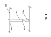
- FIG. 4 is a schematic illustrating an indicator light, a light pipe, and a housing.
- FIG. 5 is a schematic illustrating example components of an electronic deterrence device.
- security systems are often used to warn users of a security breach in progress (e.g., to notify users of an intruder entering the premises), it is often desirable to preemptively deter potential intruders from attempting to breach the premises, before any such breach occurs. This can be useful, for example, as a security breach will often result in property losses or injuries, or even death in certain instances, even if that breach was subsequently detected and a warning provided. Thus, deterring the breach from occurring at all would prevent that loss of property, injury, or death.
- deterrence can be provided using an electronic deterrence device that provides a visual indication that a premises is protected by an alarm system, regardless of whether the premises is actually being protected by an alarm system.
- An example electronic deterrence device 100 is shown in FIG. 1 .
- the electronic deterrence device 100 can be placed in one or more areas of the premises.
- the electronic deterrence device can be installed inside the premises (e.g., on an interior wall, an interior ceiling, or the interior side of a window or door) or outside the premises (e.g., on an exterior wall, a roof, or the exterior side of a window or door).
- multiple electronic deterrence devices 100 can be positioned, either inside the premises, outside the premises, or both.
- the electronic deterrence device 100 can be installed on or close to the perimeter windows on the inside of a home or business. In some cases, one or more electronic deterrence devices 100 can be used in conjunction with an alarm system. In some cases, one or more electronic deterrence devices 100 can be used alone, without an alarm system being installed in the premises.
- the electronic deterrence device 100 includes one or more indicator lights (e.g., indicator lights 102 a - b , as shown in FIG. 1 ).
- Indicator lights can be, for example, light emitting diodes (LEDs) or incandescent lamps.
- the indicator lights emit light from a relatively limited portion of the electronic deterrence device (e.g., from specific points along the exterior of the electronic deterrence device).
- the electronic deterrence device 100 can include one or more indicator lights positioned within the electronic deterrence device that illuminate a text and/or graphics displayed on the exterior of the electronic deterrence device.
- one or more indicator lights can illuminate printed or stenciled text that states “Alarmed” (e.g., message 104 , as shown in FIG. 1 ), “Warning Alarmed,” or any other suitable message, image, or indicia for deterring intruders.
- the housing can include one or more apertures having a physical arrangement corresponding to the message, images, or indicia (e.g., apertures in the shape of the characters of the message, or apertures in the shape of particular image).
- the one or more indicator lights are illuminated, light produced by the indicator lights passes through the apertures, and illuminates the message, images, or indicia.
- the housing can include material having a pattern of light attenuating and light transmissive regions (e.g., a light transmissive film having a pattern of light transmissive ink printed upon it).
- the pattern can correspond to the message, images, or indicia (e.g., light transmissive or light attuning regions in the shape of the characters of the message, or in the shape of particular image).
- the housing can include one or more optically transmissive elements (e.g., light tubes and light pipes) that receive light incident upon a first portion of the elements, transport some or all of the light to a second portion of the elements by internal reflection, and emit the transported light from the second portion.
- optically transmissive elements e.g., light tubes and light pipes
- These elements can be shaped such that the pattern of emitted light correspond to the message, images, or indicia).
- a light pipe can include a first portion disposed on or near an indicator light, and a second portion directed towards the exterior of the device and having the shape of a character of a message, or the shape of a particular image.
- a light tube or a light pipe can be constructed, for example, using a transmissive material such as polycarbonate or acrylic plastic.
- each light tube or light pipe can be surrounded by an opaque sleeve or opaque layer between its first and second portions. This can be beneficial, for example, in reducing the amount of light entering the light tube or light pipe from light sources other than the indicator light (e.g., shielding the light pipe from other surrounding indicator lights). This can be beneficial, for example, in reducing the amount of light exiting the light tube or light pipe from its middle portion.
- the indicator lights can be positioned on the electronic deterrence device 100 such that they can be readily observed.
- the indicator light 102 a can be positioned on the front surface of the electronic deterrence device 100 such that when the electronic deterrence device 100 is mounted with its back surface to a particular location (e.g., to a wall), the indicator light 102 a is visible from the exterior or perimeter of the premises (e.g., away from the wall).
- the indicator light 102 a can be positioned on the front surface of the electronic deterrence device 100 such that when the electronic deterrence device 100 is mounted with its front surface to a particular location (e.g., to a window), the indicator light 102 a is visible from the exterior or perimeter of the premises (e.g., through the window).
- a particular location e.g., to a window
- the indicator light 102 a is visible from the exterior or perimeter of the premises (e.g., through the window).
- This can be beneficial, for example, as it can indicate that the premises is protected by an alarm system, even if an alarm system is not actually installed and/or activated. Thus, potential intruders may be dissuaded from attempting to enter the premises.
- one or more of the light sources can provide information to a user of the electronic deterrence device 100 .
- indicator light 102 b can act as a low battery indicator that indicates when the electronic deterrence device 100 is low in power.
- the indicator light can be positioned on the electronic deterrence device 100 such that it is visible to an occupant of the premises, but is not visible to others outside the premises.
- the indicator light 102 b can be positioned on a side or back surface of the electronic deterrence device 100 such that when the electronic deterrence device 100 is mounted to a particular location, the indicator light 102 b is not visible from the exterior or perimeter of the premises while remaining visible to those within the premises.
- indicator lights can be placed at any appropriate location of the deterrence device, depending on the implementation.
- an electronic deterrence device can include several different indicator lights, each indicating respective information to an occupant and/or a potential intruder.
- an electronic deterrence device can include one or more indicator lights that provide information regarding an alarm system. Example indicator lights are described in greater detail with respect to FIGS. 3A-D .
- the indicator lights can be off any suitable color (e.g., red, blue, green, yellow, and so forth).
- the indicators lights can be of two or more different colors (e.g., multiple differently colored LEDs).
- one indicator light can be of one color (e.g., red), while another LED can illuminate a message with another color (e.g., blue).
- one indicator light can be of one color (e.g., blue), while another LED can illuminate a message with another color (e.g., red).
- multi-color LEDs can be used, such that each LED can illuminate any one of several colors.
- the illumination color can be varied, for example, to indicate different types of information and/or for aesthetic purposes. Although example colors and combinations are described, these are merely illustrative examples. In practice, other colors and combinations can be used, depending on the implementation.
- the indicator lights can be constantly illuminated (e.g., glowing at a constant brightness), or they can blink according to a particular intermittent pattern (e.g., blinking periodically or according to any arbitrary pattern). In some cases, multiple indicator lights can blink according to a particular pattern in combination. For example, in some cases, a first indicator light and a second indicator light can sequentially blink (e.g., one after another). As another example, in some cases, a first indicator light and a second indicator light can in blink in unison. In some cases, indicator lights can have different illumination intensities (e.g., brighter or dimmer). In some cases, the illumination behavior of the indicator lights can vary during operation of the electronic deterrence device.
- LEDs in some cases, can increase the battery life of the electronic deterrence device due to their relatively low power requirements.
- the LEDs can be periodically illuminated (e.g., using a blinking pattern, as described above), to reduce the amount of time that the LEDs are illuminated, which can further increase the battery life of the electronic deterrence device.
- the illumination pattern of the LEDs can be specified by the user (e.g., through a pattern selection switch, or other appropriate interface), or automatically by the device.
- the electronic deterrence device can be self-contained and can operate on a battery (e.g., a dry cell power source, or other suitable power source).
- a battery e.g., a dry cell power source, or other suitable power source.
- the battery can be replaced.
- replacement of the battery may require the removal of the device from its installed location.
- the battery can be replaced without removing the device (e.g., through the use of a battery housing that can be accessed without removing the device from its installed location).
- the electronic deterrence device is not self-contained, and can require electricity from an outside source (e.g., by being hardwired to a structure's electrical system).
- the electronic deterrence device can be installed at the before, after, or at the same time as the installation of other components of an alarm system.
- the electronic deterrence device can also be interconnected with the other components of the alarm system (e.g., communicatively coupled to a control panel of the alarm system) in order to interact with the other components of the alarm system.
- the electronic deterrence device can be powered from a separate DC power source, or a DC rechargeable battery backup power supply.
- multiple electronic deterrence devices can each be powered individually, or they can be interconnected and powered in series. In some cases, multiple electronic deterrence devices can be connected in a parallel wired configuration so that one power source or power supply operates all of the connected devices.
- the electronic deterrence device 100 can include a photo detector 106 (e.g., a phototransistor) that can detect the presence or the absence of light and/or an intensity of light (e.g., from the ambient environment) and adjust the behavior of the electronic deterrence device 100 accordingly.
- the electronic deterrence device 100 can illuminate the indicator lights only when the photo detector 106 determines that it is dark (e.g., when the photo detector does not detect any ambient light, or when the photo detector detects less than a threshold intensity of light).
- the electronic deterrence device 100 can illuminate the indicator lights more intensely when it determines that it is bright (e.g., during the day), and less intensely when it determines that it is dark (e.g., during the night). This can be beneficial, for example, by reducing the overall power usage of the electronic deterrence device.
- the electronic deterrence device can include a housing 108 that encloses all or some of the other components of the electronic deterrence device.
- the housing 108 can vary in size, depending on the implementation.
- the housing 108 have a length and/or width of approximately less than 1 inch, 1 inch, 2 inches, 3 inches, 4 inches, 5 inches, or more.
- the composition of the housing 108 can also vary, depending on the implementation.
- the housing can be made of plastic, metal, wood, glass, or any combination thereof.
- the electronic deterrence device can have indicator lights that are positioned such that they can be readily observed once the electronic deterrence device has been installed.
- the electronic deterrence device can include one or more mounts that can be used to facilitate proper mounting of the device to a suitable surface (e.g., a wall or window).
- the housing can include an adhesive layer (e.g., double-sided adhesive film or tape) along an exterior of the housing, such that the housing can be affixed to a surface.
- the electronic deterrence device can include a mounting anchor (e.g., a loop or sleeve), such that the electronic deterrence device can be supported by a peg, screw, or nail embedded in a surface.
- the housing can include a protruding element (e.g., a peg, a nail, or a tooth), such that the protruding element can be driven into a surface to support the electronic deterrence device upon the surface.
- the housing of the electronic deterrence device can include a mount that couples with a surface (e.g., a wall), such that when the mount is coupled with the surface, one or more particular indicator lights (e.g., the indicator light 102 a ) are facing away from the surface.
- the housing of the electronic deterrence device can include a mount that couples with a surface (e.g., a window), such that when the mount is coupled with the surface, one or more particular indicator lights (e.g., the indicator light 102 a ) are facing towards the surface.
- the electronic deterrence device can include a control module that controls the operation of the electronic deterrence device.
- a control module can control the illumination behavior of the indicator lights (e.g., by selectively applying electric current to the indicator lights to achieve certain illumination patterns).
- the control module can receive information from one or more components, interpret the information, then adjust the operation of one or more components in response.
- the control module can receive information from the photo detector, interpret the information to determine if light is present, and in response, adjust the illumination of the indicator lights.
- control module can receive information from a user (e.g., inputs entered by the user through a user interface, such as a button, switch, and dial), and in response, adjust the operation of one or more components of the electronic deterrence device.
- control module can receive information from other devices (e.g., an alarm system control panel), and in response, adjust the operation of one or more components of the electronic deterrence device.
- Example control modules are described in greater detail with respect to FIGS. 3A-D .
- the electronic deterrence device can be programmed by a user (e.g., the occupants of a premises), the user's agent (e.g., a technician installing the electronic deterrence device), and/or the manufacturer to the electronic deterrence device.
- Programming the electronic deterrence device can, in some cases, alter the performance of the electronic deterrence device in different ways. For example, in some cases, programming the electronic deterrence device can cause the device to illuminate the indicator lights differently (e.g., adjusting the rate of blinking, changing the illumination from blinking to solidly glowing and vice versa, changing the conditions under which the lights are illuminated, changing the illumination intensity, changing the illumination color, and so forth).
- the electronic deterrence device can be programmed based on commands entered through a user interface, such as a button, switch, and dial.
- the electronic deterrence device can include one or more dual in-line package (DIP) switches that correspond to certain commands or operating parameters.
- DIP switches can be used to alter the illumination behavior of one or more indicator lights (e.g., switching lights on and off, changing the blink rate, specifying whether multiple lights blink in unison or sequentially, specifying the color of illumination, and so forth).
- Each DIP switch can correspond to an individual light, or to multiple lights.
- a DIP switch can also be used to control the behavior of other components, for example to switch the photo detector on or off.
- the electronic deterrence device can be used to visually warn a potential intruder that an alarm system may be present. For example, it may indicate that the alarm system is armed, it may indicate that there is an alarm system installed in the premises, and/or it may indicate that if the intruder attempts to break in the alarm will sound and the police will be contacted (which in turn would generally result in the police responding to the emergency occurring at the premises). In some cases, the electronic deterrence device can simulate the presence of an alarm system, even if an alarm system is not present on the premises.
- the electronic deterrence device can be arranged such that, when viewed from a perspective outside of the premises (e.g., on a street), the electronic deterrence device might not be visible. However, when viewed from a perspective in closer proximity to the premises, the electronic deterrence device might be visible, depending on the surrounding ambient lighting conditions that are present both outside and/or inside the premises. This can be accomplished, for example, by positioning the electronic deterrence device in a particular location within the premises that is not readily visible from afar. This can be beneficial, for example, as it preserves the aesthetics of a premises from a distance (e.g., by hiding the electronic deterrence device), and providing deterrence when viewed from a closer distance.
- the electronic deterrence device can be mounted to a fixed or movable piece of window glass, or positioned in other areas of the premises to identify the location as being electronically protected.
- the electronic deterrence device provides a deterrent effect against criminal activity.
- Implementations of the electronic deterrence device described above may provide various benefits.
- implementations of the electronic deterrence device can provide a visual deterrent to potential intruders. This can be useful, as intruders often search for a relatively easy and/or soft target and may avoid entering a home or business which visually identifies that an alarm system is present. If the intruder approaches a home or business and observes a visual warning (e.g., as provided by an electronic deterrence device), indicating that the home or business is being protected by a security system, the intruder may be deterred from carrying out an intrusion.
- a visual warning e.g., as provided by an electronic deterrence device
- the electronic deterrence device can provide a beneficial effect to other premises in the surrounding neighborhood. For example, in many cases, neighborhoods in which security systems are densely installed have fewer incidents of residential burglaries than the neighborhoods with fewer security systems. Thus, implementations of the electronic deterrence device can increase the perceived security system installation base of a neighborhood, and further help deter intruders from breaching any premises of a neighborhood.
- the electronic deterrence device can be used independently from a security system, the electronic deterrence device can be used to provide this beneficial deterrent effect, potentially without the added cost of installing a security system.
- implementations of the electronic deterrence device described herein can be used to enhance the security of a premises, and can provide a deterrent effect against intruders, either alone or in conjunction with an alarm system.
- FIGS. 2A-D are schematics illustrating examples of electronic deterrence devices 200 a - d , each of which has a different arrangement of a housing, indicator lights, and a photo detector. Other arrangements are also possible.
- FIG. 3A Another example electronic deterrence device 300 is shown in FIG. 3A .
- the front and rear of the electronic deterrence device 300 are schematically shown in FIG. 3B and FIG. 3C , respectively.
- the electronic deterrence device 300 can be similar to those shown and described with respect to FIGS. 1 and 2A -D.
- the electronic deterrence device 300 includes a housing 308 , an indicator light 302 a positioned along a front of the electronic deterrence device 300 , and an indicator light 302 b positioned along a rear of the electronic deterrence device 300 .
- the electronic deterrence device 300 also includes a message 304 (e.g., “Alarmed”) that is illuminated by one or more indicator lights positioned within the housing 300 .
- the electronic deterrence device 300 includes several indicator lights 316 a - g , each positioned beneath respective light pipe 318 a - g .
- Each light pipe 318 a - g extends from its respective indicator light to an exterior of the housing 308 .
- FIG. 4 shows a simplified arrangement between a single indicator light 316 a , a single light pipe 318 a , and the housing 308 .
- the cross-section of the opposite end 402 b has the shape of a character of the message 304 (e.g., “A,” as shown in FIG. 3B ), and thus emits light in a pattern of the character.
- the light pipe 318 a can be surrounded by an opaque sleeve or opaque layer between ends 402 a - b (e.g., on the sides of the light pipe 318 a ). This can be beneficial, for example, in reducing the amount of light entering the light pipe 318 a from light sources other than the indicator light 316 a (e.g., shielding the light pipe from other surrounding indicator lights). This can also be beneficial, for example, in reducing the amount of light exiting the light pipe 318 a between the ends 402 a - b.
- each of the other characters of the message 304 can be illuminated by a respective indicator light 316 b - g and light pipe 318 b - g .
- each light pipe 318 b - g can be surrounded by an opaque sleeve or an opaque layer.
- the indicator lights 316 a - g are depicted in FIG. 3B as being directly visible from the exterior of the device; in practice, however, the indicator lights 316 a - g are contained within the housing 308 , and in some cases, are only visible through the light pipes 318 a - g .
- a separate indicator light and light pipe can be used to illuminate each individual character, in some cases, a single indicator light and light pipe can be used to illuminate several characters or several different portions of an image at once. Further still, in some cases, multiple indicator lights and light pipes can be used to illuminate a single character or a single portion of an image (e.g., to illuminate a character or portion of an image more brightly). Further still, in some cases, multiple indicator lights and light pipes can be used to collectively illuminate multiple characters or portions of an image. Further still, in some cases, in some cases, multiple indicator lights and a single light pipe can be used to collectively illuminate multiple characters or portions of an image.
- the electronic deterrence device 300 also includes a photo detector 306 to detect ambient light, and a switch 310 to control the operation of the electronic deterrence device 300 .
- the electronic deterrence device 300 also includes a battery 312 (e.g., a button cell battery, such as a CR2032 battery, as shown in FIG. 3C ) to power the components of the electronic deterrence device 300 .
- a battery 312 e.g., a button cell battery, such as a CR2032 battery, as shown in FIG. 3C
- the electronic deterrence device 300 can be used to indicate that a premises is protected by an alarm system, even if an alarm system is not actually installed and/or activated. Thus, potential intruders may be dissuaded from attempting to enter the premises.
- the electronic deterrence device 300 also includes a control module 314 that controls the operation of the components of the electronic deterrence device 300 .
- the control module 314 and battery 312 are depicted as being visible from the exterior of the device; in practice, however, these components are contained within the housing 308 , and are not visible from the exterior of the device.
- the arrangement of the control module 314 with respect to the other components of the electronic deterrence device 300 is shown schematically in FIG. 3D . As shown in FIG.
- the control module 314 is electrically coupled to the indicator lights 302 a - b and 304 , photo detector 306 , switch 310 , and battery 312 , such that it can send electrical signals and/or receive electrical signals from each of the components.
- the control module 314 can be any controller capable of receiving, sending, and processing electrical signals.
- the control module 314 can be a microcontroller, such as a PIC12LF1571 microcontroller (Microchip Technology, Inc., Hauppauge, N.Y.).
- control module 314 can control the components of the electronic deterrence device 300 based on the position of the switch 310 .
- the switch 310 can have three possible positions: “off,” “on,” and “auto,” each corresponding to a different operational mode. The user can manipulate the switch 310 to select one of these modes.
- the control module 314 can disable some or all of the electronic deterrence device 300 .
- the control module 314 can disable the indicator lights 302 a - b and 304 , and the photo detector 306 , such that none of these components draw a substantial amount of battery power. In some cases, the control module 314 itself can also be disabled.
- the control module 314 can supply electrical power from the battery 312 to the indicator lights 302 a and 304 such that they flash continuously (e.g., once every 1 second, 5 seconds, 10 seconds, 15 seconds, or any other interval of time). In some cases, the control module 314 can supply electrical power from the battery 312 to the indicator lights 302 a and 304 such that they are continuously illuminated (instead of flashing continuously). This mode of operation can be useful, for example, if the user wishes that the electronic deterrence device 300 continuously indicate the presence of an alarm system.
- the control module 314 can also disable the photo detector 306 (e.g., to conserve battery power), or otherwise ignore any measurements or signal obtained by the photo detector 306 .
- the control module 314 can also monitor the amount of battery power remaining in the battery 312 (e.g., by measuring a voltage across the battery 312 ), and flashing the indicator light 302 b when the battery power has dropped below a threshold value (e.g., below a threshold voltage, such as 2.7 V for a CR2032 battery).
- a threshold value e.g., below a threshold voltage, such as 2.7 V for a CR2032 battery.
- the control module 314 can supply electrical power from the battery 312 to the indicator lights 302 a and 304 only when the photo detector 306 detects less than a threshold intensity of ambient light.
- the threshold intensity of light can be, for example, an empirically determined value.
- the threshold intensity of light can be set to differentiate between night time and day time, a room being illuminated and not illuminated, or other such conditions. This mode of operation can be useful, for example, if the user wishes that the electronic deterrence device 300 indicate the presence of an alarm system when the premises is relatively dark, but not when the premises is relatively light (e.g., to save battery power).
- the threshold intensity of light can be empirically determined by a manufacturer of the electronic deterrence device 300 .
- a manufacturer can test the electronic deterrence device 300 under a variety of lighting conditions, and identify a threshold intensity of light that can be used to differentiate between night time and day time, a room being illuminated and not illuminated, or other such conditions.
- the threshold intensity of light can be empirically determined by a user of the electronic deterrence device 300 .
- a user can similarly test the electronic deterrence device 300 under a variety of lighting conditions, and identify a threshold intensity of light that can be used to differentiate between various conditions.
- the user can set the threshold intensity of light according to his particular preference.
- the control module 314 can also monitor the amount of battery power remaining in the battery 312 (e.g., by measuring a voltage across the battery 312 ), and flashing the indicator light 302 b when the battery power has dropped below a threshold value (e.g., below a threshold voltage, such as 2.7 V for a CR2032 battery).
- a threshold value e.g., below a threshold voltage, such as 2.7 V for a CR2032 battery.
- the control module 314 can determine the amount of battery power remaining in the battery 312 according to a periodic cycle. For example, in some cases, the control module 314 can obtain a measurement one every 1 second, 5 seconds, 10 seconds, or any other period of time. Similarly, the control module 314 can also obtain measurements from the photo detector 306 according to a periodic cycle. For example, in some cases, the control module 314 can obtain a measurement one every 1 second, 5 seconds, 10 seconds, or any other period of time. In some cases, the control module 314 can obtain measurements regarding the battery 312 and the photo detector 306 according to a single synchronized cycle. In some cases, the control module 314 can obtain measurements regarding the battery 312 and the photo detector 306 according to a different cycles.
- the behavior of the control module 314 can be altered by a user (e.g., the occupants of a premises), the user's agent (e.g., a technician installing the electronic deterrence device), and/or the manufacturer to the electronic deterrence device.
- the flash intervals of each indicator light, the threshold battery level, the battery measurement interval, the photo detector measurement interval, and/or any other parameter of the control module 314 can be stored by the control module 314 , and one or more of these parameters can be modified.
- Parameters can be modified, for example, using a suitable input device (e.g., a keypad, switch, dial, knob, touch sensitive surface, or other device) and/or by an external device (e.g., a separate computer system, smartphone, tablet computer, and/or other device) through an appropriate interface (e.g., a hard-wired connection port or a wireless interface).
- a suitable input device e.g., a keypad, switch, dial, knob, touch sensitive surface, or other device
- an external device e.g., a separate computer system, smartphone, tablet computer, and/or other device
- an appropriate interface e.g., a hard-wired connection port or a wireless interface
- the electronic deterrence device can include a hard-wired connection port that communicatively couples the device to a computer system via a communications cable, and the computer system can transmit information (e.g., firmware updates or commands) to modify the programming of the control module 314 to change its behavior.
- control module 314 can be communicatively coupled to the control panel of an alarm system.
- an alarm system can include a centralized control panel that allows a user to access settings associated with the alarm system, arm and disarm the alarm system, and/or modify the operational parameters of the alarm system (e.g., enable or disable various components of the alarm system and/or enable or disable protected “zones” of a premises).
- the control module 314 can be communicatively coupled to the centralized control panel, and can modify the behavior of the electronic deterrence system 300 based on the status of the alarm system.
- the control module 314 can communicate with the centralized control panel through a hard-wired connection, or through a wireless connection (e.g., a connection made via Wi-Fi, Bluetooth, Z-Wave, Thread protocol, Weave protocol, frequency hopping spread spectrum, spread spectrum, ZigBee or any other connection).
- the control module can receive information, for instance, using a wireless transceiver 502 communicatively coupled to the control module 314 (e.g., as shown in FIG. 5 ), using a communications protocol appropriate for the connection medium.
- the control module 314 can communicate with the control panel of the alarm system, determine that the alarm system is armed, and illuminate one or more indicator lights in response (e.g., by flashing indicator lights 302 a and/or 302 b according to a first frequency) and or illuminate one or more indicator lights in a particular manner (e.g., a particular color).
- the control module 314 can communicate with the control panel of the alarm system, determine that the alarm system has been triggered, and illuminate one or more indicator lights in response (e.g., by flashing indicator lights 302 a and/or 302 b according to a second faster frequency), and or illuminate one or more indicator lights in a particular manner (e.g., a different particular color).
- This can be useful, for example, as it informs a user that the alarm has been previously triggered, and that a potential dangerous situation may exist inside the premises.
- the user is made more aware of the risks, and can call others for assistance (e.g., the police, a security provider, or any other responder).
- control module 314 can communicate with the control panel of the alarm system, determine that the alarm system is disarmed, and deactivate one or more indicator lights in response.
- control module 314 can selectively illuminate and/or disable one or more indicator lights to provide information regarding the status of the alarm system.
- the control module 314 can illuminate one or more indicator lights as described above.
- the electronic deterrence device can work in unison with an alarm system when an alarm system is present, and operate independently when an alarm system is not present.
- control module can be implemented using digital electronic circuitry, or in computer software, firmware, or hardware, or in combinations of one or more of them.
- Some implementations described in this specification can be implemented as one or more groups or modules of digital electronic circuitry, computer software, firmware, or hardware, or in combinations of one or more of them. Although different modules can be used, each module need not be distinct, and multiple modules can be implemented on the same digital electronic circuitry, computer software, firmware, or hardware, or combination thereof.
- Some implementations described in this specification can be implemented as one or more computer programs, i.e., one or more modules of computer program instructions, encoded on computer storage medium for execution by, or to control the operation of, data processing apparatus.
- a computer storage medium can be, or can be included in, a computer-readable storage device, a computer-readable storage substrate, a random or serial access memory array or device, or a combination of one or more of them.
- a computer storage medium is not a propagated signal
- a computer storage medium can be a source or destination of computer program instructions encoded in an artificially generated propagated signal.
- the computer storage medium can also be, or be included in, one or more separate physical components or media (e.g., multiple CDs, disks, or other storage devices).
- the term “data processing apparatus” encompasses all kinds of apparatus, devices, and machines for processing data, including by way of example a programmable processor, a computer, a system on a chip, or multiple ones, or combinations, of the foregoing.
- the apparatus can include special purpose logic circuitry, e.g., an FPGA (field programmable gate array) or an ASIC (application specific integrated circuit).
- the apparatus can also include, in addition to hardware, code that creates an execution environment for the computer program in question, e.g., code that constitutes processor firmware, a protocol stack, a database management system, an operating system, a cross-platform runtime environment, a virtual machine, or a combination of one or more of them.
- the apparatus and execution environment can realize various different computing model infrastructures, such as web services, distributed computing and grid computing infrastructures.
- a computer program (also known as a program, software, software application, script, or code) can be written in any form of programming language, including compiled or interpreted languages, declarative or procedural languages.
- a computer program may, but need not, correspond to a file in a file system.
- a program can be stored in a portion of a file that holds other programs or data (e.g., one or more scripts stored in a markup language document), in a single file dedicated to the program in question, or in multiple coordinated files (e.g., files that store one or more modules, sub programs, or portions of code).
- a computer program can be deployed to be executed on one computer or on multiple computers that are located at one site or distributed across multiple sites and interconnected by a communication network.
- Some of the processes and logic flows described in this specification can be performed by one or more programmable processors executing one or more computer programs to perform actions by operating on input data and generating output.
- the processes and logic flows can also be performed by, and apparatus can also be implemented as, special purpose logic circuitry, e.g., an FPGA (field programmable gate array) or an ASIC (application specific integrated circuit).
- processors suitable for the execution of a computer program include, by way of example, both general and special purpose microprocessors, and processors of any kind of digital computer.
- a processor will receive instructions and data from a read only memory or a random access memory or both.
- a computer includes a processor for performing actions in accordance with instructions and one or more memory devices for storing instructions and data.
- a computer may also include, or be operatively coupled to receive data from or transfer data to, or both, one or more mass storage devices for storing data, e.g., magnetic, magneto optical disks, or optical disks.
- mass storage devices for storing data, e.g., magnetic, magneto optical disks, or optical disks.
- a computer need not have such devices.
- Devices suitable for storing computer program instructions and data include all forms of non-volatile memory, media and memory devices, including by way of example semiconductor memory devices (e.g., EPROM, EEPROM, flash memory devices, and others), magnetic disks (e.g., internal hard disks, removable disks, and others), magneto optical disks, and CD ROM and DVD-ROM disks.
- semiconductor memory devices e.g., EPROM, EEPROM, flash memory devices, and others
- magnetic disks e.g., internal hard disks, removable disks, and others
- magneto optical disks e.g., CD ROM and DVD-ROM disks.
- the processor and the memory can be supplemented by, or incorporated in, special purpose logic circuitry.
Landscapes
- Physics & Mathematics (AREA)
- General Physics & Mathematics (AREA)
- Electromagnetism (AREA)
- Business, Economics & Management (AREA)
- Emergency Management (AREA)
- Circuit Arrangement For Electric Light Sources In General (AREA)
- Engineering & Computer Science (AREA)
- Computer Security & Cryptography (AREA)
Abstract
Description
Claims (17)
Priority Applications (1)
| Application Number | Priority Date | Filing Date | Title |
|---|---|---|---|
| US14/966,677 US9542818B2 (en) | 2014-12-11 | 2015-12-11 | Electronic deterrence devices |
Applications Claiming Priority (2)
| Application Number | Priority Date | Filing Date | Title |
|---|---|---|---|
| US201462090619P | 2014-12-11 | 2014-12-11 | |
| US14/966,677 US9542818B2 (en) | 2014-12-11 | 2015-12-11 | Electronic deterrence devices |
Publications (2)
| Publication Number | Publication Date |
|---|---|
| US20160171844A1 US20160171844A1 (en) | 2016-06-16 |
| US9542818B2 true US9542818B2 (en) | 2017-01-10 |
Family
ID=56111719
Family Applications (1)
| Application Number | Title | Priority Date | Filing Date |
|---|---|---|---|
| US14/966,677 Active US9542818B2 (en) | 2014-12-11 | 2015-12-11 | Electronic deterrence devices |
Country Status (1)
| Country | Link |
|---|---|
| US (1) | US9542818B2 (en) |
Families Citing this family (3)
| Publication number | Priority date | Publication date | Assignee | Title |
|---|---|---|---|---|
| CN107509159A (en) * | 2017-06-28 | 2017-12-22 | 湖南统科技有限公司 | Fire fighting monitoring method and system based on bluetooth |
| WO2020259846A1 (en) * | 2019-06-28 | 2020-12-30 | Sedatie Centrum Nederland B.V. | Dental patient feedback and notification system |
| US20210086811A1 (en) * | 2019-09-24 | 2021-03-25 | Railway Equipment Company, Inc. | Railroad crossing gate light out detector apparatus and method |
Citations (7)
| Publication number | Priority date | Publication date | Assignee | Title |
|---|---|---|---|---|
| US20070238532A1 (en) * | 2002-03-01 | 2007-10-11 | Stethem Kenneth J | Modular personal defense device |
| US7787232B2 (en) * | 2008-02-07 | 2010-08-31 | Michael R Abatemarco | Multifunction security device |
| US8231474B2 (en) * | 2009-04-30 | 2012-07-31 | Aegis Industries, Inc. | Multi-stimulus personal defense device |
| US8245878B2 (en) * | 2007-11-02 | 2012-08-21 | Charlotte Ann Smith | Smart self defense apparatus |
| US8277328B2 (en) * | 2002-03-01 | 2012-10-02 | Aegis Industries, Inc. | Electromuscular incapacitation device and methods |
| US8363376B2 (en) * | 2008-02-07 | 2013-01-29 | Abatemarco Michael R | Multifunction security device |
| US9257026B2 (en) * | 2014-03-24 | 2016-02-09 | Loren D. Kalina | Personal self-defense device |
-
2015
- 2015-12-11 US US14/966,677 patent/US9542818B2/en active Active
Patent Citations (7)
| Publication number | Priority date | Publication date | Assignee | Title |
|---|---|---|---|---|
| US20070238532A1 (en) * | 2002-03-01 | 2007-10-11 | Stethem Kenneth J | Modular personal defense device |
| US8277328B2 (en) * | 2002-03-01 | 2012-10-02 | Aegis Industries, Inc. | Electromuscular incapacitation device and methods |
| US8245878B2 (en) * | 2007-11-02 | 2012-08-21 | Charlotte Ann Smith | Smart self defense apparatus |
| US7787232B2 (en) * | 2008-02-07 | 2010-08-31 | Michael R Abatemarco | Multifunction security device |
| US8363376B2 (en) * | 2008-02-07 | 2013-01-29 | Abatemarco Michael R | Multifunction security device |
| US8231474B2 (en) * | 2009-04-30 | 2012-07-31 | Aegis Industries, Inc. | Multi-stimulus personal defense device |
| US9257026B2 (en) * | 2014-03-24 | 2016-02-09 | Loren D. Kalina | Personal self-defense device |
Non-Patent Citations (1)
| Title |
|---|
| Maxwell Security Signs & Decals. RiteFlash Active LED /Decals. © 2011 Maxwel Alarm Screen Mfg., Inc. (Product Sheet). |
Also Published As
| Publication number | Publication date |
|---|---|
| US20160171844A1 (en) | 2016-06-16 |
Similar Documents
| Publication | Publication Date | Title |
|---|---|---|
| US20130169430A1 (en) | Apparatus and method for smoke detection & alarm | |
| US9542818B2 (en) | Electronic deterrence devices | |
| US8138928B2 (en) | Multiple event notification appliance | |
| JP2006268132A (en) | Fire alarm | |
| CN105323919B (en) | LED illumination, alarm and exit signs multifunctional headlamp system system and control method | |
| US20140009301A1 (en) | Mass notification alarm and system with programmable color output | |
| CN102473371A (en) | Illuminable indicator of electronic device being enabled based at least on user presence | |
| KR20180019107A (en) | Lighting fixtures or related improvements | |
| JPWO2008105187A1 (en) | Security device and arrangement structure of the security device | |
| KR101672733B1 (en) | Power distribution box for street light with notification function of electric leakage | |
| CN101861017A (en) | Region illumination maintenance system and method | |
| CN102865507A (en) | Intelligent indication lighting lamp and intelligent emergency lighting system thereof | |
| JP6396750B2 (en) | Fire detector or fire alarm | |
| KR20150008701A (en) | Traffic accident alarm system inside the tunnel where remote control is possible and the flash warning light | |
| KR20130052472A (en) | Lighting apparatus and driving method for thereof | |
| CN201993936U (en) | Intrusion-preventing alarming and practical-training system | |
| CN205026407U (en) | LED throws light on, reports an emergency and asks for help or increased vigilance and evacuate multi -functional banks system that instructs | |
| GB2562171A (en) | An emergency exit sign | |
| KR20190045752A (en) | Smart sign for preventing crime | |
| JP2011258533A (en) | Led illumination lamp and management system of the same | |
| KR20170100130A (en) | Out door parking guiding system | |
| JP2007242446A (en) | Illumination device, illumination system, and abnormality announcement method | |
| TWI706382B (en) | Smart lamp and site management system | |
| JP2017211810A (en) | Disaster prevent equipment | |
| JP2010218928A (en) | Display lamp |
Legal Events
| Date | Code | Title | Description |
|---|---|---|---|
| AS | Assignment |
Owner name: ZWIRN, JEFFREY D., UNITED STATES Free format text: ASSIGNMENT OF ASSIGNORS INTEREST;ASSIGNOR:BRODEUR, CHARLES;REEL/FRAME:037413/0202 Effective date: 20151229 |
|
| AS | Assignment |
Owner name: ZWIRN, JEFFREY D., NEW JERSEY Free format text: CORRECTIVE ASSIGNMENT TO CORRECT THE ADDRESS OF THE ASSIGNEE/ STATE PREVIOUSLY RECORDED AT REEL: 037413 FRAME: 0202. ASSIGNOR(S) HEREBY CONFIRMS THE ASSIGNMENT;ASSIGNOR:BRODEUR, CHARLES;REEL/FRAME:037490/0020 Effective date: 20151229 |
|
| STCF | Information on status: patent grant |
Free format text: PATENTED CASE |
|
| AS | Assignment |
Owner name: ZWIRN CORPORATION, NEW JERSEY Free format text: ASSIGNMENT OF ASSIGNORS INTEREST;ASSIGNOR:ZWIRN, JEFFREY D.;REEL/FRAME:047576/0980 Effective date: 20181121 |
|
| MAFP | Maintenance fee payment |
Free format text: PAYMENT OF MAINTENANCE FEE, 4TH YR, SMALL ENTITY (ORIGINAL EVENT CODE: M2551); ENTITY STATUS OF PATENT OWNER: SMALL ENTITY Year of fee payment: 4 |