US9542108B2 - Efficient migration of virtual storage devices to a remote node using snapshots - Google Patents
Efficient migration of virtual storage devices to a remote node using snapshots Download PDFInfo
- Publication number
- US9542108B2 US9542108B2 US14/320,427 US201414320427A US9542108B2 US 9542108 B2 US9542108 B2 US 9542108B2 US 201414320427 A US201414320427 A US 201414320427A US 9542108 B2 US9542108 B2 US 9542108B2
- Authority
- US
- United States
- Prior art keywords
- node
- resource
- changes
- additional
- vsd
- Prior art date
- Legal status (The legal status is an assumption and is not a legal conclusion. Google has not performed a legal analysis and makes no representation as to the accuracy of the status listed.)
- Active, expires
Links
- 230000005012 migration Effects 0.000 title claims abstract description 46
- 238000013508 migration Methods 0.000 title claims abstract description 46
- 238000000034 method Methods 0.000 claims abstract description 56
- 230000004048 modification Effects 0.000 claims description 10
- 238000012986 modification Methods 0.000 claims description 10
- 230000004044 response Effects 0.000 claims description 5
- 230000003247 decreasing effect Effects 0.000 claims description 4
- 238000004590 computer program Methods 0.000 abstract description 4
- 238000000581 reactive spray deposition Methods 0.000 description 41
- 230000008569 process Effects 0.000 description 11
- 238000010586 diagram Methods 0.000 description 8
- 239000000872 buffer Substances 0.000 description 6
- 238000004891 communication Methods 0.000 description 6
- 238000012546 transfer Methods 0.000 description 6
- 230000006870 function Effects 0.000 description 5
- 239000004065 semiconductor Substances 0.000 description 5
- 238000013507 mapping Methods 0.000 description 3
- 230000005540 biological transmission Effects 0.000 description 2
- 230000008859 change Effects 0.000 description 2
- 238000012545 processing Methods 0.000 description 2
- 230000008901 benefit Effects 0.000 description 1
- 238000013500 data storage Methods 0.000 description 1
- 238000005516 engineering process Methods 0.000 description 1
- 230000007717 exclusion Effects 0.000 description 1
- 239000000835 fiber Substances 0.000 description 1
- RGNPBRKPHBKNKX-UHFFFAOYSA-N hexaflumuron Chemical compound C1=C(Cl)C(OC(F)(F)C(F)F)=C(Cl)C=C1NC(=O)NC(=O)C1=C(F)C=CC=C1F RGNPBRKPHBKNKX-UHFFFAOYSA-N 0.000 description 1
- 230000006872 improvement Effects 0.000 description 1
- 239000004973 liquid crystal related substance Substances 0.000 description 1
- 230000007246 mechanism Effects 0.000 description 1
- 238000012544 monitoring process Methods 0.000 description 1
- 230000003287 optical effect Effects 0.000 description 1
- 230000002093 peripheral effect Effects 0.000 description 1
- 230000001681 protective effect Effects 0.000 description 1
- 238000011084 recovery Methods 0.000 description 1
- 230000009467 reduction Effects 0.000 description 1
- 239000007787 solid Substances 0.000 description 1
- 230000001360 synchronised effect Effects 0.000 description 1
- 238000012360 testing method Methods 0.000 description 1
- 230000001960 triggered effect Effects 0.000 description 1
Images


Classifications
-
- G—PHYSICS
- G06—COMPUTING; CALCULATING OR COUNTING
- G06F—ELECTRIC DIGITAL DATA PROCESSING
- G06F3/00—Input arrangements for transferring data to be processed into a form capable of being handled by the computer; Output arrangements for transferring data from processing unit to output unit, e.g. interface arrangements
- G06F3/06—Digital input from, or digital output to, record carriers, e.g. RAID, emulated record carriers or networked record carriers
- G06F3/0601—Interfaces specially adapted for storage systems
- G06F3/0602—Interfaces specially adapted for storage systems specifically adapted to achieve a particular effect
- G06F3/0614—Improving the reliability of storage systems
- G06F3/0619—Improving the reliability of storage systems in relation to data integrity, e.g. data losses, bit errors
-
- G—PHYSICS
- G06—COMPUTING; CALCULATING OR COUNTING
- G06F—ELECTRIC DIGITAL DATA PROCESSING
- G06F11/00—Error detection; Error correction; Monitoring
- G06F11/07—Responding to the occurrence of a fault, e.g. fault tolerance
- G06F11/14—Error detection or correction of the data by redundancy in operation
- G06F11/1402—Saving, restoring, recovering or retrying
- G06F11/1446—Point-in-time backing up or restoration of persistent data
-
- G—PHYSICS
- G06—COMPUTING; CALCULATING OR COUNTING
- G06F—ELECTRIC DIGITAL DATA PROCESSING
- G06F3/00—Input arrangements for transferring data to be processed into a form capable of being handled by the computer; Output arrangements for transferring data from processing unit to output unit, e.g. interface arrangements
- G06F3/06—Digital input from, or digital output to, record carriers, e.g. RAID, emulated record carriers or networked record carriers
- G06F3/0601—Interfaces specially adapted for storage systems
- G06F3/0602—Interfaces specially adapted for storage systems specifically adapted to achieve a particular effect
- G06F3/061—Improving I/O performance
-
- G—PHYSICS
- G06—COMPUTING; CALCULATING OR COUNTING
- G06F—ELECTRIC DIGITAL DATA PROCESSING
- G06F3/00—Input arrangements for transferring data to be processed into a form capable of being handled by the computer; Output arrangements for transferring data from processing unit to output unit, e.g. interface arrangements
- G06F3/06—Digital input from, or digital output to, record carriers, e.g. RAID, emulated record carriers or networked record carriers
- G06F3/0601—Interfaces specially adapted for storage systems
- G06F3/0628—Interfaces specially adapted for storage systems making use of a particular technique
- G06F3/0646—Horizontal data movement in storage systems, i.e. moving data in between storage devices or systems
- G06F3/0647—Migration mechanisms
-
- G—PHYSICS
- G06—COMPUTING; CALCULATING OR COUNTING
- G06F—ELECTRIC DIGITAL DATA PROCESSING
- G06F3/00—Input arrangements for transferring data to be processed into a form capable of being handled by the computer; Output arrangements for transferring data from processing unit to output unit, e.g. interface arrangements
- G06F3/06—Digital input from, or digital output to, record carriers, e.g. RAID, emulated record carriers or networked record carriers
- G06F3/0601—Interfaces specially adapted for storage systems
- G06F3/0628—Interfaces specially adapted for storage systems making use of a particular technique
- G06F3/0646—Horizontal data movement in storage systems, i.e. moving data in between storage devices or systems
- G06F3/065—Replication mechanisms
-
- G—PHYSICS
- G06—COMPUTING; CALCULATING OR COUNTING
- G06F—ELECTRIC DIGITAL DATA PROCESSING
- G06F3/00—Input arrangements for transferring data to be processed into a form capable of being handled by the computer; Output arrangements for transferring data from processing unit to output unit, e.g. interface arrangements
- G06F3/06—Digital input from, or digital output to, record carriers, e.g. RAID, emulated record carriers or networked record carriers
- G06F3/0601—Interfaces specially adapted for storage systems
- G06F3/0668—Interfaces specially adapted for storage systems adopting a particular infrastructure
- G06F3/067—Distributed or networked storage systems, e.g. storage area networks [SAN], network attached storage [NAS]
-
- G—PHYSICS
- G06—COMPUTING; CALCULATING OR COUNTING
- G06F—ELECTRIC DIGITAL DATA PROCESSING
- G06F9/00—Arrangements for program control, e.g. control units
- G06F9/06—Arrangements for program control, e.g. control units using stored programs, i.e. using an internal store of processing equipment to receive or retain programs
- G06F9/46—Multiprogramming arrangements
- G06F9/48—Program initiating; Program switching, e.g. by interrupt
- G06F9/4806—Task transfer initiation or dispatching
- G06F9/4843—Task transfer initiation or dispatching by program, e.g. task dispatcher, supervisor, operating system
- G06F9/485—Task life-cycle, e.g. stopping, restarting, resuming execution
- G06F9/4856—Task life-cycle, e.g. stopping, restarting, resuming execution resumption being on a different machine, e.g. task migration, virtual machine migration
-
- G—PHYSICS
- G06—COMPUTING; CALCULATING OR COUNTING
- G06F—ELECTRIC DIGITAL DATA PROCESSING
- G06F9/00—Arrangements for program control, e.g. control units
- G06F9/06—Arrangements for program control, e.g. control units using stored programs, i.e. using an internal store of processing equipment to receive or retain programs
- G06F9/46—Multiprogramming arrangements
- G06F9/50—Allocation of resources, e.g. of the central processing unit [CPU]
- G06F9/5083—Techniques for rebalancing the load in a distributed system
- G06F9/5088—Techniques for rebalancing the load in a distributed system involving task migration
-
- G—PHYSICS
- G06—COMPUTING; CALCULATING OR COUNTING
- G06F—ELECTRIC DIGITAL DATA PROCESSING
- G06F11/00—Error detection; Error correction; Monitoring
- G06F11/07—Responding to the occurrence of a fault, e.g. fault tolerance
- G06F11/14—Error detection or correction of the data by redundancy in operation
- G06F11/1402—Saving, restoring, recovering or retrying
- G06F11/1446—Point-in-time backing up or restoration of persistent data
- G06F11/1456—Hardware arrangements for backup
-
- G—PHYSICS
- G06—COMPUTING; CALCULATING OR COUNTING
- G06F—ELECTRIC DIGITAL DATA PROCESSING
- G06F16/00—Information retrieval; Database structures therefor; File system structures therefor
- G06F16/10—File systems; File servers
- G06F16/11—File system administration, e.g. details of archiving or snapshots
- G06F16/128—Details of file system snapshots on the file-level, e.g. snapshot creation, administration, deletion
-
- G06F17/30088—
-
- G—PHYSICS
- G06—COMPUTING; CALCULATING OR COUNTING
- G06F—ELECTRIC DIGITAL DATA PROCESSING
- G06F2201/00—Indexing scheme relating to error detection, to error correction, and to monitoring
- G06F2201/81—Threshold
-
- G—PHYSICS
- G06—COMPUTING; CALCULATING OR COUNTING
- G06F—ELECTRIC DIGITAL DATA PROCESSING
- G06F2201/00—Indexing scheme relating to error detection, to error correction, and to monitoring
- G06F2201/815—Virtual
-
- G—PHYSICS
- G06—COMPUTING; CALCULATING OR COUNTING
- G06F—ELECTRIC DIGITAL DATA PROCESSING
- G06F2201/00—Indexing scheme relating to error detection, to error correction, and to monitoring
- G06F2201/84—Using snapshots, i.e. a logical point-in-time copy of the data
-
- G—PHYSICS
- G06—COMPUTING; CALCULATING OR COUNTING
- G06F—ELECTRIC DIGITAL DATA PROCESSING
- G06F3/00—Input arrangements for transferring data to be processed into a form capable of being handled by the computer; Output arrangements for transferring data from processing unit to output unit, e.g. interface arrangements
- G06F3/06—Digital input from, or digital output to, record carriers, e.g. RAID, emulated record carriers or networked record carriers
- G06F3/0601—Interfaces specially adapted for storage systems
- G06F3/0628—Interfaces specially adapted for storage systems making use of a particular technique
- G06F3/0662—Virtualisation aspects
- G06F3/0665—Virtualisation aspects at area level, e.g. provisioning of virtual or logical volumes
Definitions
- the present invention relates to virtual machines, and more particularly to a technique for migrating virtual storage devices between nodes.
- Modem systems that implement a plurality of virtual machines running on separate nodes may include functionality to copy a virtual resource such as a virtual storage device from one node to a different node. Migration of the resource thereby enables the resource to be utilized by a different virtual machine running on different hardware.
- a virtual resource such as a virtual storage device
- Migration of the resource thereby enables the resource to be utilized by a different virtual machine running on different hardware.
- resources may be extremely large and the data that represents the resource may need to be transported over a network infrastructure. This data transfer may take hours or days to be copied from one node to another node. Thus, there is a need for addressing this issue and/or other issues associated with the prior art.
- a system, method, and computer program product are provided for performing fast migration of a virtual resource from one node to another node.
- the method includes the steps of receiving a first request to migrate a resource from a first node to a second node, transmitting a second request to the second node to create a new instance of the resource, collecting a set of changes associated with the resource in a data structure, and transmitting the data structure that includes the set of changes to the second node.
- the second node generates the new instance of the resource based on a snapshot of the resource captured by the first node at a previous point in time and updates the new instance of the resource based on the set of changes such that the new instance of the resource on the second node matches the resource on the first node.
- FIG. 1 illustrates a flowchart of a method for migrating a virtual resource from a first node to a second node, according to one embodiment
- FIG. 2 illustrates a cluster having a plurality of nodes, in accordance with one embodiment
- FIGS. 3A & 3B are conceptual diagrams of the architecture for a node of FIG. 2 , in accordance with one embodiment
- FIG. 4 illustrates the abstraction layers implemented by the block engine daemon for two nodes of the cluster, in accordance with one embodiment
- FIG. 5A is a conceptual diagram for a system configured to create snapshots of a VSD, in accordance with one embodiment
- FIG. 5B is a conceptual diagram of the system configured to implement a migration of the VSD from the first node to the second node using previously captured snapshots, in accordance with one embodiment
- FIGS. 6A & 6B illustrate a flowchart of a method for migrating a VSD from a first node to a second node, in accordance with another embodiment
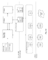
- FIG. 7 illustrates an exemplary system in which the various architecture and/or functionality of the various previous embodiments may be implemented.
- Virtual resources such as a virtual storage device may be implemented on particular nodes of a system that includes a plurality of nodes. During operation, the virtual resources may need to be moved from one node to another node such that the virtual resource is implemented by different hardware. Such operations may be referred to as a migration operation.
- Migration operations typically take a long time due to the nature of the large amount of data that is being transferred from one node to another node.
- some systems also implement a system for creating backup versions of such resources called snapshots.
- a snapshot is a copy of all of the data for a resource at a particular point in time.
- the snapshots may be stored in different nodes so that if a node fails, the snapshot can be used to restore a resource on that node or a different node such that the data in the resource is not lost.
- Migration operations may take advantage of these snapshots in order to reduce the time required to perform the migration operation.
- FIG. 1 illustrates a flowchart of a method 100 for migrating a virtual resource from a first node to a second node, according to one embodiment.
- the method 100 is described in the context of a program executed by a processor, the method 100 may also be performed by custom circuitry or by a combination of custom circuitry and a program.
- a request is received to migrate a resource from a first node to a second node.
- the resource is a virtual storage device that maps blocks of one or more physical storage devices to a contiguous address space.
- the resource may be a virtual machine or some other type of data structure comprising state and data stored in a memory.
- a request is transmitted to the second node to create a new instance of the resource.
- the second node in response to receiving the request, is configured to generate the new instance of the resource in a memory associated with the second node based on a snapshot of the resource captured by the first node at a previous point in time and stored in the memory associated with the second node.
- the snapshot comprises a data structure that represents a copy of the resource on the first node at the previous point in time.
- the snapshot may contain a reference to a previous snapshot as well as data that represents any changes to the resource since the previous snapshot was captured.
- the first node collects a set of changes made to the resource since the previous point in time in a data structure.
- the data structure may comprise zero or more changes.
- a change refers to a command and/or data that represents any modification to the resource.
- a request to write data to a virtual storage device comprises a change that is stored in the data structure.
- the data structure that includes the set of changes is transmitted to the second node to update the new instance of the resource.
- the second node is configured to apply the set of changes to the new instance of the resource such that the original resource on the first node matches the new instance of the resource on the second node.
- FIG. 2 illustrates a cluster 200 having a plurality of nodes 210 , in accordance with one embodiment.
- the cluster 200 includes/nodes (i.e., node 210 ( 0 ), node 210 ( 1 ), . . . , node 210 (J- 1 )).
- Each node 210 includes a processor 211 , a memory 212 , a NIC 213 , and one or more real storage devices (RSD) 214 .
- the processor 211 may be an x86-based processor, a RISC-based processor, or the like.
- the memory 212 may be a volatile memory such as a Synchronous Dynamic Random-Access Memory (SDRAM) or the like.
- SDRAM Synchronous Dynamic Random-Access Memory
- the NIC 213 may implement a physical layer and media access control (MAC) protocol layer for a network interface.
- the physical layer may correspond to various physical network interfaces such as IEEE (Institute of Electrical and Electronics Engineers) 802.3 (Ethernet), IEEE 802.11 (WiFi), and the like.
- the memory 212 includes a host operating system kernel, one or more device drivers, one or more applications, and the like.
- the host operating system kernel may be, e.g., based on the Linux® kernel such as the Red Hat® Enterprise Linux (RHEL) distribution.
- RHEL Red Hat® Enterprise Linux
- each node 210 may include one or more other devices such as GPUs, additional microprocessors, displays, radios, or the like.
- an RSD 214 is a physical, non-volatile memory device such as a HDD, an optical disk drive, a solid state drive, a magnetic tape drive, and the like that is capable of storing data.
- the one or more RSDs 214 may be accessed via an asynchronous input/output functionality implemented by a standard library of the host operating system or accessed via a non-standard library that is loaded by the operating system, in lieu of or in addition to the standard library.
- the host operating system may mount the RSDs 214 and enable block device drivers to access the RSDs 214 for read and write access.
- the RSDs 214 may implement a file system including, but not limited to, the FAT32 (File Allocation Table—32-bit) file system, NTFS (New Technology File System), or the ext2 (extended file system 2 ).
- each RSD 214 may implement logical block addressing (LBA).
- LBA is an abstraction layer that maps blocks of the disk (e.g., 512B blocks of a hard disk) to a single unified address.
- the unified address may be 28-bit, 48-bit, or 64-bit wide that can be mapped, e.g., to a particular cylinder/head/sector tuple of a conventional HDD or other data storage space.
- the memory 212 may also include a hypervisor that performs hardware virtualization.
- QEMU Quality EMUlator
- each node 210 may be configured to load a host operating system such as RHEL into the memory 212 on boot. Once the host operating system is running, the QEMU software is launched in order to instantiate one or more VMs on the node 210 , each VM implementing a guest operating system that may or may not be the same as the host operating system.
- QEMU may generate VMs that can emulate a variety of different hardware architectures such as x86, PowerPC, SPARC, and the like.
- FIGS. 3A & 3B are conceptual diagrams of the architecture for a node 210 of FIG. 2 , in accordance with one embodiment.
- the node 210 may execute a host operating system 311 that implements a protected mode of operation having at least two privilege levels including a kernel space 302 and a user space 304 .
- the host operating system 311 may comprise the Linux® kernel as well as one or more device drivers 312 and 313 that execute in the kernel space 302 .
- the device drivers 312 enable applications in the user space 304 to read or write data from/to the RSDs 214 via a physical interface such as SATA (serial ATA), SCSI (Small Computer System Interface), FC (Fibre Channel), and the like.
- the device drivers 312 are generic block device drivers included in the host operating system 311 .
- the device driver 313 enables applications to communicate with other nodes 210 in the cluster 200 via a network interface, which may be wired (e.g., SONET/SDH, IEEE 802.3, etc.) or wireless (e.g., IEEE 802.11, etc.).
- the device driver 313 is a generic network driver included in the host operating system 311 .
- FIG. 3A shows the RSDs 214 and network 370 within the hardware abstraction layer.
- the RSDs 214 and network 370 comprise physical devices having a physical interface to the processor 211 in the node 210 , either directly or indirectly through a system bus or bridge device.
- FIG. 3A also illustrates a software abstraction layer that includes objects and processes resident in the memory 212 of the node 210 . The processes may be executed by the processor 211 .
- the host operating system 311 , system monitor (SysMon) 320 , Block Engine (BE) Daemon 350 , and virtual machines (VMs) 360 are processes that are executed by the processor 211 .
- the host operating system 311 may allocate a portion of the memory 212 as a shared memory 315 that is accessible by the one or more VMs 360 .
- the VMs 360 may share data in the shared memory 315 .
- the host operating system 311 may execute one or more processes configured to implement portions of the architecture for a node 210 .
- the host operating system 311 executes the BE Daemon 350 in the user space 304 .
- the BE Daemon 350 is a background process that performs tasks related to the block devices coupled to the node 210 (i.e., the RSDs 214 ).
- the SysMon 320 implements a state machine (SM) 321 and a set of collectors 322 for managing the instantiation and execution of one or more VMs 360 that are executed in the user space 304 .
- the SysMon 320 may be configured to manage the provisioning of virtual storage devices (VSDs).
- VSDs may be mounted to the VMs 360 to provide applications running on the VMs 360 access to the RSDs 214 even though the applications executed by the VMs 360 cannot access the RSDs 214 directly.
- the SysMon 320 creates I/O buffers 316 in the shared memory 315 that enable the VMs 360 to read data from or write data to the VSDs mounted to the VM 360 .
- Each VM 360 may be associated with multiple I/O buffers 316 in the shared memory 315 .
- each VSD mounted to the VM 360 may be associated with an input buffer and an output buffer, and multiple VSDs may be mounted to each VM 360 .
- each instance of the VM 360 implements a guest operating system 361 , a block device driver 362 , and a block engine client 363 .
- the guest OS 361 may be the same as or different from the host operating system 311 .
- the guest OS 361 comprises a kernel 365 that implements a virtual I/O driver 366 that is logically coupled to a VSD.
- Each VSD is a logical storage device that maps non-contiguous blocks of storage in one or more RSDs 214 to a contiguous, logical address space of the VSD.
- the VSD logically appears and operates like a real device coupled to a physical interface for the guest OS 361 , but is actually an abstraction layer between the guest OS 361 and the physical storage blocks on the RSDs 214 coupled to the node 210 , either directly or indirectly via the network 370 .
- the guest OS 361 may execute one or more applications 364 that can read and write data to the VSD via the virtual I/O driver 366 .
- two or more VSDs may be associated with a single VM 360 .
- the block device driver 362 and the BE client 363 implement a logical interface between the guest OS 361 and the VSD.
- the block device driver 362 receives read and write requests from the virtual I/O driver 366 of the guest OS 361 .
- the block device driver 362 is configured to write data to and read data from the corresponding I/O buffers 316 in the shared memory 315 .
- the BE client 363 is configured to communicate with the BE server 352 in the BE Daemon 350 to schedule I/O requests for the VSDs.
- the BE Daemon 350 implements a Block Engine Remote Protocol 351 , a Block Engine Server 352 , an I/O Manager 353 , and a VSD Engine 354 .
- the Block Engine Remote Protocol 351 provides access to remote RSDs 214 coupled to other nodes 210 in the cluster 200 via the network 370 .
- the BE Server 352 communicates with one or more BE Clients 363 included in the VMs 360 .
- the BE Client 363 generates I/O requests related to one or more VSDs for the BE Server 352 , which then manages the execution of those requests via either the Block Engine Remote Protocol 351 (for RSDs 214 connected to other nodes 210 accessible via the network 370 ) or the I/O Manager 353 (for RSDs 214 connected to the node 210 ).
- the I/O Manager 353 enables the BE Daemon 350 to generate asynchronous UO operations that are handled by the host OS 311 to read from or write data to the RSDs 214 connected to the node 210 .
- Functions implemented by the I/O Manager 353 enable the BE Daemon 350 to schedule I/O requests for one or more VMs 360 in an efficient manner.
- the BE Daemon 350 also implements a VSD Engine 354 .
- the VSD Engine 354 maintains state and metadata associated with a plurality of VSD objects 355 .
- Each VSD object 355 may include a mapping table that associates each block of addresses (i.e., an address range) in the VSD with a corresponding block of addresses in one or more RSDs 214 .
- the VSD objects 355 may include various state associated with a VSD such as a VSD identifier (i.e., handle), a base address of the VSD object 355 in the memory 212 , a size of the VSD, a format of the VSD (e.g., filesystem, block size, etc.), and the like.
- the VSD Engine 354 may also maintain state and metadata associated with a plurality of RSD objects 356 .
- Each RSD object 356 may correspond to an RSD 214 connected to the node 210 or an RSD 214 accessible on another node 210 via the network 370 .
- the RSD objects 356 may include various state associated with the RSDs 214 such as an RSD identifier (i.e., handle), a base address of the RSD object 356 in the memory 212 , a size of the RSD 214 , a format of the RSD 214 (e.g., filesystem, block size, etc.), and the like.
- the RSD object 214 may also track errors associated with the RSD 214 .
- the VSD objects 355 and the RSD objects 356 are abstraction layers implemented by the VSD Engine 354 that enable VMs 360 , via the BE Daemon 350 , to store data on the RSDs 214 .
- the VSD abstraction layer is a set of objects defined using an object-oriented programming (OOP) language.
- OOP object-oriented programming
- an object is an instantiation of a class and comprises a data structure in memory that includes fields and pointers to methods implemented by the class.
- the VSD abstraction layer defines a VSD class that implements a common interface for all VSD objects that includes the following methods: Create; Open; Close; Read; Write; Flush; Discard; and a set of methods for creating a snapshot of the VSD.
- a snapshot is a data structure that stores the state of the VSD at a particular point in time.
- the Create method generates the metadata associated with a VSD and stores the metadata on an RSD 214 , making the VSD available to all nodes 210 in the cluster 200 .
- the Open method enables applications in the VMs 360 to access the VSD (i.e., the I/O buffers 316 are generated in the shared memory 315 and the VSD is mounted to the guest OS 361 ).
- the Close method prevents applications in the VMs 360 from accessing the VSD.
- the Read method enables the BE Server 352 to read data from the VSD.
- the Write method enables the BE Server 352 to write data to the VSD.
- the Flush method flushes all pending I/O requests associated with the VSD.
- the Discard method discards a particular portion of data stored in memory associated with the VSD.
- VSD objects 355 inherit from the generic VSD class: a SimpleVSD object and a ReliableVSD object.
- the SimpleVSD object is a simple virtual storage device that maps each block of addresses in the VSD to a single, corresponding block of addresses in an RSD 214 . In other words, each block of data in the SimpleVSD object is only stored in a single location.
- the SimpleVSD object provides a high performance virtual storage solution but lacks reliability.
- the ReliableVSD object is a redundant storage device that maps each block of addresses in the VSD to two or more corresponding blocks in two or more RSDs 214 . In other words, the ReliableVSD object provides n-way replicated data and metadata.
- the ReliableVSD object may also implement error checking with optional data and/or metadata checksums.
- the ReliableVSD object may be configured to store up to 15 redundant copies (i.e., 16 total copies) of the data stored in the VSD.
- the SimpleVSD object may be used for non-important data while the ReliableVSD object attempts to store data in a manner that prevents a single point of failure (SPOF) as well as provide certain automatic recovery capabilities when one or more nodes experiences a failure.
- the VSD Engine 354 may manage multiple types of VSD objects 355 simultaneously such that some data may be stored on SimpleVSD type VSDs and other data may be stored on ReliableVSD type VSDs. It will be appreciated that the two types of VSDs described herein are only two possible examples of VSD objects inheriting from the VSD class and other types of VSD objects 355 are contemplated as being within the scope of the present disclosure.
- the VSD Engine 354 may also implement an RSD abstraction layer that provides access to all of the RSDs 214 coupled to the one or more nodes 210 of the cluster 200 .
- the RSD abstraction layer enables communications with both local and remote RSDs 214 .
- a local RSD is an RSD 214 included in a particular node 210 that is hosting the instance of the BE Daemon 350 .
- a remote RSD is an RSD 214 included in a node 210 that is not hosting the instance of the BE Daemon 350 and is accessible via a network 370 .
- the RSD abstraction layer provides reliable communications as well as passing disk or media errors from both local and remote RSDs 214 to the BE Daemon 350 .
- the RSD abstraction layer is a set of objects defined using an OOP language.
- the RSD abstraction layer defines an RSD class that implements a common interface for all RSD objects 356 that includes the following methods: Read; Write; Allocate; and UpdateRefCounts.
- Each RSD object 356 is associated with a single RSD 214 .
- the methods of the RSD class are controlled by a pair of state machines that may be triggered by either the reception of packets from remote nodes 210 on the network 370 or the expiration of timers (e.g., interrupts).
- the Read method enables BE Server 352 to read data from the RSD 214 .
- the Write method enables BE Server 352 to write data to the RSD 214 .
- the Allocate method allocates a block of memory in the RSD 214 for storing data.
- the UpdateRefCounts method updates the reference counts for each block of the RSD 214 , enabling deallocation of blocks with reference counts of zero (i.e., garbage collection).
- two types of RSD objects 356 inherit from the RSD class: an RSDLocal object and an RSDRemote object.
- the RSDLocal object implements the interface defined by the RSD class for local RSDs 214
- the RSDRemote object implements the interface defined by the RSD class for remote RSDs 214 .
- the main difference between the RSDLocal objects and the RSDRemote objects are that the I/O Manager 353 asynchronously handles all I/O between the BE Server 352 and local RSDs 214 , while the BE Remote Protocol 351 handles all I/O between the BE Server 352 and remote RSDs 214 .
- the SysMon 320 is responsible for the provisioning and monitoring of VSDs.
- the SysMon 320 includes logic for generating instances of the VSD objects 355 and the RSD objects 356 in the memory 212 based on various parameters. For example, the SysMon 320 may discover how many RSDs 214 are connected to the nodes 210 of the cluster 200 and create a different RSD object 356 for each RSD 214 discovered. The SysMon 320 may also include logic for determining how many VSD objects should be created and or shared by the VMs 360 implemented on the node 210 . Once the SysMon 320 has generated the instances of the VSD objects 355 and the RSD objects 356 in the memory 212 , the BE Daemon 350 is configured to manage the functions of the VSDs and the RSDs 214 .
- FIG. 4 is a conceptual diagram of the abstraction layers implemented by the BE Daemon 350 for two nodes 210 of the cluster 200 , in accordance with one embodiment.
- a first node 210 ( 0 ) is coupled to two local RSDs (i.e., 214 ( 0 ) and 214 ( 1 )) and two remote RSDs (i.e., 214 ( 2 ) and 214 ( 3 )) via the network 370 .
- a second node 210 ( 1 ) is coupled to two local RSDs (i.e., 214 ( 2 ) and 214 ( 3 )) and two remote RSDs (i.e., 214 ( 0 ) and 214 ( 1 )) via the network 370 .
- the RSD abstraction layer includes four RSD objects 356 (i.e., RSD 0 , RSD 1 , RSD 2 , and RSD 3 ).
- RSD 0 and RSD 1 are RSDLocal objects and RSD 2 and RSD 3 are RSDRemote objects.
- the first node 210 ( 0 ) accesses the first RSD 214 ( 0 ) and the second RSD 214 ( 1 ) via the I/O Manager library that makes system calls to the host operating system 311 in order to asynchronously read or write data to the local RSDs 214 .
- An RSDLocal library is configured to provide an interface for applications communicating with the BE Daemon 350 to read or write to the local RSDs 214 .
- the RSDLocal library may call methods defined by the interface implemented by the IOManager library.
- the first node 210 ( 0 ) accesses the third RSD 214 ( 2 ) and the fourth RSD 214 ( 3 ) indirectly via a Protocol Data Unit Peer (PDUPeer) library that makes system calls to the host operating system 311 in order to communicate with other nodes 210 using the NIC 213 .
- the PDUPeer library generates packets that include I/O requests for the remote RSDs (e.g., 214 ( 2 ) and 214 ( 3 )).
- the packets may include information that specifies the type of request as well as data or a pointer to the data in the memory 212 .
- a packet may include data and a request to write the data to one of the remote RSDs 214 .
- the request may include an address that specifies a block in the RSD 214 to write the data to and a size of the data.
- a packet may include a request to read data from the remote RSD 214 .
- the RSDProxy library unpacks requests from the packets received from the PDUPeer library and transmits the requests to the associated local RSD objects 356 as if the requests originated within the node 210 .
- the BE Remote Protocol 351 , the BE Server 352 , and the I/O Manager 353 implement various aspects of the RSD abstraction layer shown in FIG. 4 .
- the BE Remote Protocol 351 implements the RSDRremote library, RSDProxy library, and the PDUPeer library
- the I/O Manager 353 implements the RSDLocal library and the IOManager library.
- the second node 210 ( 1 ) is configured similarly to the first node 210 ( 0 ) except that the RSD objects 356 RSD 0 and RSD 1 are RSDRemote objects linked to the first RSD 214 ( 0 ) and the second RSD 214 ( 1 ), respectively, and the RSD objects 356 RSD 2 and RSD 3 are RSDLocal objects linked to the third RSD 214 ( 2 ) and the fourth RSD 214 ( 3 ), respectively.
- the VSD abstraction layer includes three VSD objects 355 (i.e., VSD 0 , VSD 1 , and VSD 2 ).
- VSD 0 and VSD 1 are ReliableVSD objects.
- VSD 2 is a ReliableVSD object.
- the VSD objects 355 may be instantiated as SimpleVSD objects, and that the particular types of objects chosen depends on the characteristics of the system.
- the VSD objects 355 provide an interface to map I/O requests associated with the corresponding VSD to one or more corresponding I/O requests associated with one or more RSDs 214 .
- the VSD objects 355 through the Read or Write methods, are configured to translate the I/O request received from the BE Server 352 and generate corresponding I/O requests for the RSD(s) 214 based on the mapping table included in the VSD object 355 .
- the translated I/O request is transmitted to the corresponding RSD 214 via the Read or Write methods in the RSD object 356 .
- FIG. 5A is a conceptual diagram for a system 500 configured to create snapshots of a VSD, in accordance with one embodiment.
- the system 500 includes a first node 502 and a second node 504 .
- the system 500 may be configured to capture snapshots of a VSD associated with the first node 502 and transfer the snapshots to the second node 504 in order to keep a backup of the VSD in case the first node 502 crashes.
- a snapshot is a data structure that represents a copy of all of the data associated with the VSD at a particular point in time.
- the snapshot includes both the metadata associated with the VSD stored in the VSD object 355 and the data stored in one or more RSDs 214 that are referenced in the mapping table of the VSD object 355 .
- the first snapshot of the VSD may comprise a complete copy of all of the data in the VSD.
- Subsequent snapshots of the VSD may comprise only that data in the VSD that has changed since a point in time when the last snapshot was captured as well as a reference pointer to the last snapshot such that the VSD can be reconstructed through a chain of one or more previous snapshots. By only storing the changed data in the subsequent snapshots, less disk capacity may be required.
- the hypervisor 320 may be configured to create snapshots of the VSDs on a particular node and transmit the snapshots to other nodes in the cluster 200 as a backup.
- the hypervisor 320 on one node may communicate with the hypervisor 320 on other nodes to perform these functions.
- an operation to capture a first snapshot 511 of the VSD may be initiated on the first node 502 .
- the first node 502 captures the snapshot of the VSD and transmits the snapshot to the second node 504 for storage.
- the data set included in the snapshot of the VSD which may include not only the VSD object 355 but also the data referenced by the VSD object 355 , may be quite large and can take some time to transfer from the first node 502 to the second node 504 .
- the first node 502 and the second node 504 may be located at different physical locations and configured to communicate over a network such as the Internet.
- the large data set that makes up the captured snapshot may take minutes, hours, or even days to transfer to the second node 504 over the Internet.
- the snapshot is broken down into data packets in the first node 502 that are transmitted via a TCP/IP protocol over the network and reassembled into the snapshot at the second node 504 .
- a second operation to capture a second snapshot 512 of the VSD may be initiated in the first node 502 .
- the first node 502 captures another snapshot of the VSD and transmits the second snapshot to the second node 504 for storage.
- the second snapshot may be smaller than the first snapshot because the second snapshot may only include data that has changed in the VSD since the first snapshot was captured. Since the second snapshot is likely to be smaller than the first snapshot, the second snapshot may be transferred to the second node 504 in less time than it took to transfer the first snapshot to the second node 504 .
- a third operation to capture a third snapshot 513 of the VSD may be initiated in the first node 502 .
- the first node 502 captures yet another snapshot of the VSD and transfers the third snapshot to the second node 504 .
- FIG. 5B is a conceptual diagram of the system 500 configured to implement a migration of the VSD from the first node 502 to the second node 504 using previously captured snapshots, in accordance with one embodiment.
- migration of a virtual machine or portions of a virtual machine, such as a VSD from one node to another node are performed by halting the virtual machine on one node, copying the memory comprising the virtual machine from that node to a new node, and then executing the virtual machine on the new node.
- a virtual machine or portions of a virtual machine such as a VSD
- migration can be used to move an entire system (i.e., virtual machine) from one node to another node, or migration can be used to move only a portion of the system (i.e., a storage device associated with the virtual machine) from one node to another node.
- the hypervisor 320 for a node receives a request to migrate a VSD from that node to another node in the cluster 200 .
- the request may be generated by a process configured to manage the cluster 200 or the request may be generated by a system manager using software executing on that node or another node.
- the request may include a pointer to a different node that is the target node for the migration operation.
- an operation to perform migration of a VSD is configured to utilize one or more snapshots of the VSD that are stored on the target node. For example, as shown in FIG. 5B , a first snapshot 511 and a second snapshot 512 of a VSD are captured on a first node 502 at two points in time.
- the system 500 may be configured to store these snapshots on a second node 504 as a backup of the VSD in case the first node 502 fails.
- the first node 502 receives a request 515 to migrate the VSD from the first node 502 to the second node 504 .
- the first node 502 selects a previously captured snapshot of the VSD that is already stored on the second node 504 . In this case, the previously captured snapshot is the second snapshot 512 .
- the system 500 can reduce the amount of data that is required to be copied from the first node 502 to the second node 504 to complete a migration by utilizing the data that has already been copied as part of the backup system using snapshots.
- the first node 502 is configured to track any changes made to the VSD since the last snapshot was captured and collect these changes in a data structure that represents the set of changes.
- the first node 502 may track these changes in order to capture another subsequent snapshot at a later point in time.
- the set of changes that are collected may also be used in order to migrate the VSD from the first node 502 to the second node 504 .
- the first node 502 tracks the changes to the VSD during a first period of time 521 after capturing the second snapshot 512 and collects the set of changes in a data structure that represents the modifications made to the VSD.
- the first node 502 may send a request to the second node 504 to create a new VSD on the second node 504 using the local copy of the second snapshot 512 (i.e., the copy previously transmitted to the second node 504 ).
- the second node 504 may create the new VSD by creating a copy of the VSD object 355 in a memory 315 of the second node 504 and copying the data referenced by the second VSD into one or more RSDs 214 associated with the second node 504 .
- the first node 502 may then transmit the data structure that represents the modifications made to the VSD during the first period of time 521 to the second node 504 .
- the second node 504 receives the data structure and may utilize the data structure to update the local copy of the VSD on the second node 504 to match the remote copy of the VSD on the first node 502 at a particular point in time. Once the second node 504 has updated the local copy of the VSD, the local copy of the VSD matches the remote copy of the VSD at a point in time when the request 515 to migrate the VSD was received. Creating a local copy of the VSD on the second node 504 using the second snapshot 512 is significantly faster than transferring a current copy of the VSD to the second node 504 over a network. By only transmitting the changes to the VSD since the previous snapshot was captured over the network, the migration of the VSD may reduce the required bandwidth when compared to conventional systems that simply copy the entire contents of the resource from one node to another node.
- the first node 502 may mark the VSD as read-only to prevent any additional changes to the VSD from happening after the migration operation is started. Because of the reduction in data being transmitted over the network, the time it takes to migrate the VSD to the second node 504 is reduced and having the VSD be put into a read-only protection mode may not be as much of an issue.
- the VSD may be maintained in a normal operating state (i.e., at least one process has read-write permissions for the VSD) that allows additional operations to be performed while the migration is on-going.
- processes on the first node 502 may be allowed to continue to write data to the VSD on the first node 502 even after the migration is started.
- a second duration of time 522 has elapsed in the time it takes to transmit the set of changes collected during the first duration of time 521 to the second node 504 .
- the second duration of time 522 corresponds to a timeframe required to transmit the data structure to the second node 504 via the network.
- the second duration of time 522 may not be insignificant and it will be appreciated that additional changes to the VSD may be made during this time by the processes running on the first node 502 .
- the first node 502 determines whether any additional changes have been collected during the second duration of time 522 . If any changes have been collected, then the first node 502 will need to transmit a second set of changes to the second node 504 so that the local copy of the VSD on the second node 504 can be updated.
- This procedure can be repeated a number of times until there are no changes made to the VSD during the time it takes to transmit the previous set of changes to the second node 504 . If no additional changes are made during that time, then the migration is complete and the resource, such as the virtual machine on the first node 502 , may be halted and operations may be transferred to the second node 504 .
- the first node 502 may repeatedly transmit the changes to the second node 504 until the set of changes collected while transmitting the previous set of changes to the second node 504 is below a threshold value. If the set of changes is below a threshold value (i.e., the size of the data structure that represents the modifications to the VSD is below some threshold value), then the first node 502 may put the VSD into a protective mode to prevent any additional changes to be made to the VSD. Then, the first node 502 may transmit the last set of changes to the second node 504 to complete the migration operation.
- a threshold value i.e., the size of the data structure that represents the modifications to the VSD is below some threshold value
- the second set of changes is collected during the second duration of time 522 and transmitted to the second node 504 during a third duration of time 523 .
- the size of the data structure storing the second set of changes may be larger than the threshold value, so the VSD remains in a normal operating mode.
- a third set of changes is collected.
- the size of the data structure storing the third set of changes may be below the threshold value such that the first node 502 places the VSD in a protected operating mode that prevents any further modification to the VSD.
- the third set of changes is then transmitted to the second node 504 during a fourth duration of time 524 to complete the migration operation.
- the migration operation may be bounded such that if the migration operation hasn't completed after a set period of time (i.e., a timeout period), then the VSD may be placed in a protected operating mode such that the migration operation can be completed.
- a set period of time i.e., a timeout period
- the timeout period may be configured as a constant amount of time, such as 1 hour, or may be variable based on various characteristics.
- the timeout period may be decreased because this may indicate that processes are making too many changes to the VSD to finish the migration. However, if each subsequent set of changes are decreasing in size, then the timeout period may be increased to allow for the migration to complete without an interruption to the resource. In another embodiment, the timeout period may be set based on the size of the resource being migrated. For example, the timeout period for a VSD with a capacity of 1 GB of data may be shorter than the timeout period for a VSD with a capacity of 10 GB of data.
- FIGS. 6A & 6B illustrate a flowchart of a method 600 for migrating a VSD from a first node 502 to a second node 504 , in accordance with another embodiment.
- the method is described in the context of a program executed by a processor, the method may also be performed by custom circuitry or by a combination of custom circuitry and a program.
- the first node 502 captures a snapshot of a VSD.
- the first node 502 transmits the snapshot to the second node 504 to be stored in a memory (e.g., shared memory 315 or an RSD 214 ) associated with the second node 504 .
- the first node 502 receives a request to migrate the VSD from the first node 502 to the second node 504 .
- the first node 502 transmits a second request to the second node 504 to create a new instance of the VSD.
- the second node 504 is configured to generate a new instance of the VSD object 355 in a memory 315 of the second node 504 based on the snapshot of the VSD stored in the memory.
- the second node 504 may also copy data included with the snapshot into one or more RSDs 214 of the second node 504 .
- the first node 502 collects a set of changes associated with the VSD in a data structure. The set of changes represents any modifications made to the VSD since the snapshot was captured.
- the first node 502 tracks modifications made to the VSD even before the request to migrate the VSD to the second node is received.
- the first node 502 transmits the data structure to the second node 504 to update the new instance of the VSD.
- the second node 504 is configured to unpack the set of changes in the data structure and modify the new instance of the VSD based on the set of changes such that the new instance of the VSD in the second node 504 matches the original VSD in the first node 502 at a point in time that the request to migrate the VSD was received.
- the first node 502 collects an additional set of changes associated with the VSD in an additional data structure while the previous set of changes is transmitted to the second node 504 . Because the first node 502 and the second node 504 are connected via a network, transmitting the data structure to the second node takes time. In order to keep the VSD operational on the first node 502 during this time, any additional changes made to the VSD should be tracked and collected to send to the second node 504 once the previous set of changes has been received by the second node 504 .
- the first node 502 transmits the additional data structure to the second node to update the new instance of the VSD.
- the second node 504 is configured to unpack the set of changes in the additional data structure and modify the new instance of the VSD based on the additional set of changes such that the new instance of the VSD in the second node 504 matches the original VSD in the first node 502 at a point in time when the first node 502 had completed transmission of the previous set of changes to the second node 504 .
- the first node 502 determines whether a period of time has elapsed since the start of the migration operation that is greater than a timeout period.
- the first node 502 may check the period of time against the timeout period before beginning the transmission of the additional data structure. If the period of time is not greater than the timeout period, then, at step 620 , the first node 502 determines whether the size of the data structure storing the additional set of changes is less than a threshold value.
- the threshold value may represent a size (in bytes) of the data structure used to store the additional set of changes.
- any other test for determining whether the size of the data structure storing the additional set of changes is small may be applied by the first node 502 . If the size of the data structure storing the additional set of changes is not less than the threshold value, then the method 600 returns to step 614 where another iteration of collecting changes and transmitting changes to the second node 504 is performed. However, if the size of the data structure storing the additional set of changes is less than the threshold value, then, at step 622 , the first node 502 configures the VSD to operate in a protected operating mode. In one embodiment, the first node 502 changes the permissions of any processes that have access to the VSD to be read-only. The protected operating mode prevents any additional changes from being made to the VSD while the last set of changes is transmitted to the second node 504 .
- step 618 if the period of time is greater than the timeout period, then the method 600 proceeds directly to step 622 , described above, and no additional iterations of collecting changes and transmitting changes to the second node 504 are performed.
- the migration operation is complete. Once the migration operation is complete, the VSD in the first node 502 may be deleted and the VSD may be unmapped from any virtual machines on the first node 502 . In addition, any memory 315 allocated to the VSD in the first node 502 may be freed or overwritten with other data.
- FIG. 7 illustrates an exemplary system 700 in which the various architecture and/or functionality of the various previous embodiments may be implemented.
- the system 700 may comprise a node 210 of the cluster 200 .
- a system 700 is provided including at least one central processor 701 that is connected to a communication bus 702 .
- the communication bus 702 may be implemented using any suitable protocol, such as PCI (Peripheral Component Interconnect), PCI-Express, AGP (Accelerated Graphics Port), HyperTransport, or any other bus or point-to-point communication protocol(s).
- the system 700 also includes a main memory 704 . Control logic (software) and data are stored in the main memory 704 which may take the form of random access memory (RAM).
- RAM random access memory
- the system 700 also includes input devices 712 , a graphics processor 706 , and a display 708 , i.e. a conventional CRT (cathode ray tube), LCD (liquid crystal display), LED (light emitting diode), plasma display or the like.
- User input may be received from the input devices 712 , e.g., keyboard, mouse, touchpad, microphone, and the like.
- the graphics processor 706 may include a plurality of shader modules, a rasterization module, etc. Each of the foregoing modules may even be situated on a single semiconductor platform to form a graphics processing unit (GPU).
- GPU graphics processing unit
- a single semiconductor platform may refer to a sole unitary semiconductor-based integrated circuit or chip. It should be noted that the term single semiconductor platform may also refer to multi-chip modules with increased connectivity which simulate on-chip operation, and make substantial improvements over utilizing a conventional central processing unit (CPU) and bus implementation. Of course, the various modules may also be situated separately or in various combinations of semiconductor platforms per the desires of the user.
- CPU central processing unit
- the system 700 may also include a secondary storage 710 .
- the secondary storage 610 includes, for example, a hard disk drive and/or a removable storage drive, representing a floppy disk drive, a magnetic tape drive, a compact disk drive, digital versatile disk (DVD) drive, recording device, universal serial bus (USB) flash memory.
- the removable storage drive reads from and/or writes to a removable storage unit in a well-known manner.
- Computer programs, or computer control logic algorithms may be stored in the main memory 704 and/or the secondary storage 710 . Such computer programs, when executed, enable the system 700 to perform various functions.
- the memory 704 , the storage 710 , and/or any other storage are possible examples of computer-readable media.
- the architecture and/or functionality of the various previous figures may be implemented in the context of the central processor 701 , the graphics processor 706 , an integrated circuit (not shown) that is capable of at least a portion of the capabilities of both the central processor 701 and the graphics processor 706 , a chipset (i.e., a group of integrated circuits designed to work and sold as a unit for performing related functions, etc.), and/or any other integrated circuit for that matter.
- a chipset i.e., a group of integrated circuits designed to work and sold as a unit for performing related functions, etc.
- the architecture and/or functionality of the various previous figures may be implemented in the context of a general computer system, a circuit board system, a game console system dedicated for entertainment purposes, an application-specific system, and/or any other desired system.
- the system 700 may take the form of a desktop computer, laptop computer, server, workstation, game consoles, embedded system, and/or any other type of logic.
- the system 700 may take the form of various other devices including, but not limited to a personal digital assistant (PDA) device, a mobile phone device, a television, etc.
- PDA personal digital assistant
- system 700 may be coupled to a network (e.g., a telecommunications network, local area network (LAN), wireless network, wide area network (WAN) such as the Internet, peer-to-peer network, cable network, or the like) for communication purposes.
- a network e.g., a telecommunications network, local area network (LAN), wireless network, wide area network (WAN) such as the Internet, peer-to-peer network, cable network, or the like
- LAN local area network
- WAN wide area network
- peer-to-peer network such as the Internet
- cable network or the like
Abstract
Description
Claims (20)
Priority Applications (1)
| Application Number | Priority Date | Filing Date | Title |
|---|---|---|---|
| US14/320,427 US9542108B2 (en) | 2014-06-30 | 2014-06-30 | Efficient migration of virtual storage devices to a remote node using snapshots |
Applications Claiming Priority (1)
| Application Number | Priority Date | Filing Date | Title |
|---|---|---|---|
| US14/320,427 US9542108B2 (en) | 2014-06-30 | 2014-06-30 | Efficient migration of virtual storage devices to a remote node using snapshots |
Publications (2)
| Publication Number | Publication Date |
|---|---|
| US20150378623A1 US20150378623A1 (en) | 2015-12-31 |
| US9542108B2 true US9542108B2 (en) | 2017-01-10 |
Family
ID=54930493
Family Applications (1)
| Application Number | Title | Priority Date | Filing Date |
|---|---|---|---|
| US14/320,427 Active 2034-11-11 US9542108B2 (en) | 2014-06-30 | 2014-06-30 | Efficient migration of virtual storage devices to a remote node using snapshots |
Country Status (1)
| Country | Link |
|---|---|
| US (1) | US9542108B2 (en) |
Cited By (2)
| Publication number | Priority date | Publication date | Assignee | Title |
|---|---|---|---|---|
| US11409619B2 (en) | 2020-04-29 | 2022-08-09 | The Research Foundation For The State University Of New York | Recovering a virtual machine after failure of post-copy live migration |
| US11983079B2 (en) | 2022-08-08 | 2024-05-14 | The Research Foundation For The State University Of New York | Recovering a virtual machine after failure of post-copy live migration |
Families Citing this family (6)
| Publication number | Priority date | Publication date | Assignee | Title |
|---|---|---|---|---|
| US9350682B1 (en) * | 2014-07-30 | 2016-05-24 | Amazon Technologies, Inc. | Compute instance migrations across availability zones of a provider network |
| US10108502B1 (en) * | 2015-06-26 | 2018-10-23 | EMC IP Holding Company LLC | Data protection using checkpoint restart for cluster shared resources |
| US10120766B2 (en) * | 2015-10-16 | 2018-11-06 | Business Objects Software Limited | Model-based system and method for undoing actions in an application |
| US10659325B2 (en) * | 2016-06-15 | 2020-05-19 | Thousandeyes, Inc. | Monitoring enterprise networks with endpoint agents |
| CN109842636A (en) * | 2017-11-24 | 2019-06-04 | 阿里巴巴集团控股有限公司 | Cloud service moving method, device and electronic equipment |
| US11567840B2 (en) * | 2020-03-09 | 2023-01-31 | Rubrik, Inc. | Node level recovery for clustered databases |
Citations (5)
| Publication number | Priority date | Publication date | Assignee | Title |
|---|---|---|---|---|
| US20030101321A1 (en) * | 2001-11-29 | 2003-05-29 | Ohran Richard S. | Preserving a snapshot of selected data of a mass storage system |
| US20100185587A1 (en) * | 2009-01-09 | 2010-07-22 | Microsoft Corporation | Data movement with reduced service outage |
| US8161254B2 (en) * | 2008-06-02 | 2012-04-17 | Syncsort Incorporated | Method for creating consistent backup image of a storage volume without requiring a snapshot |
| US20120266018A1 (en) * | 2011-04-11 | 2012-10-18 | Nec Corporation | Fault-tolerant computer system, fault-tolerant computer system control method and recording medium storing control program for fault-tolerant computer system |
| US20130054530A1 (en) * | 2011-08-29 | 2013-02-28 | Oracle International Corporation | Live file system migration |
-
2014
- 2014-06-30 US US14/320,427 patent/US9542108B2/en active Active
Patent Citations (5)
| Publication number | Priority date | Publication date | Assignee | Title |
|---|---|---|---|---|
| US20030101321A1 (en) * | 2001-11-29 | 2003-05-29 | Ohran Richard S. | Preserving a snapshot of selected data of a mass storage system |
| US8161254B2 (en) * | 2008-06-02 | 2012-04-17 | Syncsort Incorporated | Method for creating consistent backup image of a storage volume without requiring a snapshot |
| US20100185587A1 (en) * | 2009-01-09 | 2010-07-22 | Microsoft Corporation | Data movement with reduced service outage |
| US20120266018A1 (en) * | 2011-04-11 | 2012-10-18 | Nec Corporation | Fault-tolerant computer system, fault-tolerant computer system control method and recording medium storing control program for fault-tolerant computer system |
| US20130054530A1 (en) * | 2011-08-29 | 2013-02-28 | Oracle International Corporation | Live file system migration |
Cited By (2)
| Publication number | Priority date | Publication date | Assignee | Title |
|---|---|---|---|---|
| US11409619B2 (en) | 2020-04-29 | 2022-08-09 | The Research Foundation For The State University Of New York | Recovering a virtual machine after failure of post-copy live migration |
| US11983079B2 (en) | 2022-08-08 | 2024-05-14 | The Research Foundation For The State University Of New York | Recovering a virtual machine after failure of post-copy live migration |
Also Published As
| Publication number | Publication date |
|---|---|
| US20150378623A1 (en) | 2015-12-31 |
Similar Documents
| Publication | Publication Date | Title |
|---|---|---|
| US9542108B2 (en) | Efficient migration of virtual storage devices to a remote node using snapshots | |
| US10740016B2 (en) | Management of block storage devices based on access frequency wherein migration of block is based on maximum and minimum heat values of data structure that maps heat values to block identifiers, said block identifiers are also mapped to said heat values in first data structure | |
| US10200471B2 (en) | Workload migration across a hybrid network | |
| US11307935B2 (en) | Management of volume snapshots in a data storage system | |
| US9697130B2 (en) | Systems and methods for storage service automation | |
| US9898274B2 (en) | Replacing an accelerator firmware image without operating system reboot | |
| US9639432B2 (en) | Live rollback for a computing environment | |
| US9928091B2 (en) | Techniques for streaming virtual machines from a server to a host | |
| US10564996B2 (en) | Parentless virtual machine forking | |
| US20170339225A1 (en) | Workload migration across a hybrid network | |
| US20150106802A1 (en) | Replicating virtual machines across different virtualization platforms | |
| US9740627B2 (en) | Placement engine for a block device | |
| US9436386B2 (en) | Shared reference counters among a plurality of virtual storage devices | |
| US20150244802A1 (en) | Importing and exporting virtual disk images | |
| US10909102B2 (en) | Systems and methods for performing scalable Log-Structured Merge (LSM) tree compaction using sharding | |
| US20180054357A1 (en) | Discovering Changes of Network Interface Controller Names | |
| US11842051B2 (en) | Intelligent defragmentation in a storage system | |
| US9870242B2 (en) | Parallel mapping of client partition memory to multiple physical adapters | |
| US10176023B2 (en) | Task dispatcher for block storage devices | |
| US20170351447A1 (en) | Data protection implementation for block storage devices | |
| WO2022222977A1 (en) | Method and apparatus for managing memory of physical server for running cloud service instances | |
| US11972284B2 (en) | Virtual machine memory snapshots in persistent memory | |
| US11640375B2 (en) | Avoiding data inconsistency in a file system using 2-level synchronization | |
| US11947501B2 (en) | Two-hierarchy file system | |
| US9092530B1 (en) | Systems and methods for rapidly provisioning virtual storage objects |
Legal Events
| Date | Code | Title | Description |
|---|---|---|---|
| AS | Assignment |
Owner name: SCALE COMPUTING, INC., INDIANA Free format text: ASSIGNMENT OF ASSIGNORS INTEREST;ASSIGNOR:WHITE, PHILIP ANDREW;REEL/FRAME:033242/0692 Effective date: 20140627 |
|
| STCF | Information on status: patent grant |
Free format text: PATENTED CASE |
|
| AS | Assignment |
Owner name: PACIFIC WESTERN BANK, NORTH CAROLINA Free format text: SECURITY INTEREST;ASSIGNOR:SCALE COMPUTING, INC.;REEL/FRAME:041003/0765 Effective date: 20170111 |
|
| AS | Assignment |
Owner name: BET ASSOCIATES III, LLC, PENNSYLVANIA Free format text: SECURITY AGREEMENT;ASSIGNOR:SCALE COMPUTING, INC.;REEL/FRAME:043820/0802 Effective date: 20170907 |
|
| AS | Assignment |
Owner name: SCALE COMPUTING, INC., INDIANA Free format text: RELEASE BY SECURED PARTY;ASSIGNOR:PACIFIC WESTERN BANK;REEL/FRAME:043572/0750 Effective date: 20170906 |
|
| AS | Assignment |
Owner name: RUNWAY GROWTH CREDIT FUND INC., ILLINOIS Free format text: SECURITY INTEREST;ASSIGNOR:SCALE COMPUTING, INC.;REEL/FRAME:048745/0653 Effective date: 20190329 Owner name: SCALE COMPUTING, INC., INDIANA Free format text: RELEASE BY SECURED PARTY;ASSIGNOR:BET ASSOCIATES III, LLC;REEL/FRAME:048747/0302 Effective date: 20190329 |
|
| FEPP | Fee payment procedure |
Free format text: MAINTENANCE FEE REMINDER MAILED (ORIGINAL EVENT CODE: REM.); ENTITY STATUS OF PATENT OWNER: SMALL ENTITY |
|
| FEPP | Fee payment procedure |
Free format text: SURCHARGE FOR LATE PAYMENT, SMALL ENTITY (ORIGINAL EVENT CODE: M2554); ENTITY STATUS OF PATENT OWNER: SMALL ENTITY |
|
| MAFP | Maintenance fee payment |
Free format text: PAYMENT OF MAINTENANCE FEE, 4TH YR, SMALL ENTITY (ORIGINAL EVENT CODE: M2551); ENTITY STATUS OF PATENT OWNER: SMALL ENTITY Year of fee payment: 4 |
|
| AS | Assignment |
Owner name: SCALE COMPUTING, INC., INDIANA Free format text: RELEASE BY SECURED PARTY;ASSIGNOR:RUNWAY GROWTH CREDIT FUND INC., AS AGENT;REEL/FRAME:054611/0589 Effective date: 20201210 |
|
| AS | Assignment |
Owner name: SCALE COMPUTING, INC., INDIANA Free format text: RELEASE BY SECURED PARTY;ASSIGNOR:RUNWAY GROWTH CREDIT FUND INC.;REEL/FRAME:054619/0802 Effective date: 20201209 Owner name: AVENUE VENTURE OPPORTUNITIES FUND, L.P., NEW YORK Free format text: SECURITY INTEREST;ASSIGNOR:SCALE COMPUTING, INC.;REEL/FRAME:054619/0825 Effective date: 20201211 |
|
| AS | Assignment |
Owner name: NORTH HAVEN EXPANSION CREDIT II LP, NEW YORK Free format text: SECURITY INTEREST;ASSIGNOR:SCALE COMPUTING, INC.;REEL/FRAME:062586/0059 Effective date: 20220622 |
|
| AS | Assignment |
Owner name: SCALE COMPUTING, INC., NEW YORK Free format text: RELEASE BY SECURED PARTY;ASSIGNOR:AVENUE VENTURE OPPORTUNITIES FUND, L.P.;REEL/FRAME:062603/0565 Effective date: 20230206 |
|
| AS | Assignment |
Owner name: PACIFIC WESTERN BANK, NORTH CAROLINA Free format text: SECURITY INTEREST;ASSIGNOR:SCALE COMPUTING, INC.;REEL/FRAME:065213/0109 Effective date: 20230403 |