US9540101B2 - System, apparatus and method for long endurance vertical takeoff and landing vehicle - Google Patents
System, apparatus and method for long endurance vertical takeoff and landing vehicle Download PDFInfo
- Publication number
- US9540101B2 US9540101B2 US14/507,198 US201414507198A US9540101B2 US 9540101 B2 US9540101 B2 US 9540101B2 US 201414507198 A US201414507198 A US 201414507198A US 9540101 B2 US9540101 B2 US 9540101B2
- Authority
- US
- United States
- Prior art keywords
- wing
- fuselage
- vtol aircraft
- support
- ground
- Prior art date
- Legal status (The legal status is an assumption and is not a legal conclusion. Google has not performed a legal analysis and makes no representation as to the accuracy of the status listed.)
- Active
Links
- 238000000034 method Methods 0.000 title claims description 24
- 239000003381 stabilizer Substances 0.000 claims abstract description 22
- 230000007704 transition Effects 0.000 description 27
- 238000011084 recovery Methods 0.000 description 19
- 238000013461 design Methods 0.000 description 15
- 238000004891 communication Methods 0.000 description 12
- 230000005484 gravity Effects 0.000 description 10
- 230000008901 benefit Effects 0.000 description 7
- 238000010586 diagram Methods 0.000 description 7
- 238000013459 approach Methods 0.000 description 6
- 230000007246 mechanism Effects 0.000 description 6
- 230000006870 function Effects 0.000 description 4
- 238000012423 maintenance Methods 0.000 description 4
- 238000005259 measurement Methods 0.000 description 4
- 238000012986 modification Methods 0.000 description 4
- 230000004048 modification Effects 0.000 description 4
- RZVHIXYEVGDQDX-UHFFFAOYSA-N 9,10-anthraquinone Chemical compound C1=CC=C2C(=O)C3=CC=CC=C3C(=O)C2=C1 RZVHIXYEVGDQDX-UHFFFAOYSA-N 0.000 description 3
- 238000004364 calculation method Methods 0.000 description 3
- 239000000446 fuel Substances 0.000 description 3
- 230000033001 locomotion Effects 0.000 description 3
- 238000001228 spectrum Methods 0.000 description 3
- 239000005441 aurora Substances 0.000 description 2
- 238000011217 control strategy Methods 0.000 description 2
- 230000000694 effects Effects 0.000 description 2
- 238000005516 engineering process Methods 0.000 description 2
- 238000010348 incorporation Methods 0.000 description 2
- 238000010297 mechanical methods and process Methods 0.000 description 2
- 230000000284 resting effect Effects 0.000 description 2
- 239000011435 rock Substances 0.000 description 2
- 238000012360 testing method Methods 0.000 description 2
- 230000000007 visual effect Effects 0.000 description 2
- 241000985905 Candidatus Phytoplasma solani Species 0.000 description 1
- 241000566150 Pandion haliaetus Species 0.000 description 1
- 230000001133 acceleration Effects 0.000 description 1
- 230000003044 adaptive effect Effects 0.000 description 1
- 238000005452 bending Methods 0.000 description 1
- 230000015556 catabolic process Effects 0.000 description 1
- 230000001413 cellular effect Effects 0.000 description 1
- 230000002860 competitive effect Effects 0.000 description 1
- 230000000295 complement effect Effects 0.000 description 1
- 239000000470 constituent Substances 0.000 description 1
- 238000010276 construction Methods 0.000 description 1
- 238000012937 correction Methods 0.000 description 1
- 239000012636 effector Substances 0.000 description 1
- 230000010006 flight Effects 0.000 description 1
- 239000012530 fluid Substances 0.000 description 1
- 230000037406 food intake Effects 0.000 description 1
- 230000003993 interaction Effects 0.000 description 1
- 230000003287 optical effect Effects 0.000 description 1
- 238000000819 phase cycle Methods 0.000 description 1
- 230000009467 reduction Effects 0.000 description 1
- 230000004044 response Effects 0.000 description 1
- 102220047090 rs6152 Human genes 0.000 description 1
- 239000000523 sample Substances 0.000 description 1
- 238000004088 simulation Methods 0.000 description 1
- 238000012546 transfer Methods 0.000 description 1
Images


Classifications
-
- B—PERFORMING OPERATIONS; TRANSPORTING
- B64—AIRCRAFT; AVIATION; COSMONAUTICS
- B64C—AEROPLANES; HELICOPTERS
- B64C27/00—Rotorcraft; Rotors peculiar thereto
- B64C27/52—Tilting of rotor bodily relative to fuselage
-
- B—PERFORMING OPERATIONS; TRANSPORTING
- B64—AIRCRAFT; AVIATION; COSMONAUTICS
- B64C—AEROPLANES; HELICOPTERS
- B64C13/00—Control systems or transmitting systems for actuating flying-control surfaces, lift-increasing flaps, air brakes, or spoilers
- B64C13/02—Initiating means
- B64C13/16—Initiating means actuated automatically, e.g. responsive to gust detectors
-
- B—PERFORMING OPERATIONS; TRANSPORTING
- B64—AIRCRAFT; AVIATION; COSMONAUTICS
- B64C—AEROPLANES; HELICOPTERS
- B64C25/00—Alighting gear
- B64C25/02—Undercarriages
- B64C25/08—Undercarriages non-fixed, e.g. jettisonable
- B64C25/10—Undercarriages non-fixed, e.g. jettisonable retractable, foldable, or the like
-
- B—PERFORMING OPERATIONS; TRANSPORTING
- B64—AIRCRAFT; AVIATION; COSMONAUTICS
- B64C—AEROPLANES; HELICOPTERS
- B64C29/00—Aircraft capable of landing or taking-off vertically, e.g. vertical take-off and landing [VTOL] aircraft
-
- B—PERFORMING OPERATIONS; TRANSPORTING
- B64—AIRCRAFT; AVIATION; COSMONAUTICS
- B64C—AEROPLANES; HELICOPTERS
- B64C29/00—Aircraft capable of landing or taking-off vertically, e.g. vertical take-off and landing [VTOL] aircraft
- B64C29/0008—Aircraft capable of landing or taking-off vertically, e.g. vertical take-off and landing [VTOL] aircraft having its flight directional axis horizontal when grounded
- B64C29/0016—Aircraft capable of landing or taking-off vertically, e.g. vertical take-off and landing [VTOL] aircraft having its flight directional axis horizontal when grounded the lift during taking-off being created by free or ducted propellers or by blowers
- B64C29/0033—Aircraft capable of landing or taking-off vertically, e.g. vertical take-off and landing [VTOL] aircraft having its flight directional axis horizontal when grounded the lift during taking-off being created by free or ducted propellers or by blowers the propellers being tiltable relative to the fuselage
-
- B—PERFORMING OPERATIONS; TRANSPORTING
- B64—AIRCRAFT; AVIATION; COSMONAUTICS
- B64C—AEROPLANES; HELICOPTERS
- B64C29/00—Aircraft capable of landing or taking-off vertically, e.g. vertical take-off and landing [VTOL] aircraft
- B64C29/0091—Accessories not provided for elsewhere
-
- B—PERFORMING OPERATIONS; TRANSPORTING
- B64—AIRCRAFT; AVIATION; COSMONAUTICS
- B64C—AEROPLANES; HELICOPTERS
- B64C29/00—Aircraft capable of landing or taking-off vertically, e.g. vertical take-off and landing [VTOL] aircraft
- B64C29/02—Aircraft capable of landing or taking-off vertically, e.g. vertical take-off and landing [VTOL] aircraft having its flight directional axis vertical when grounded
- B64C29/04—Aircraft capable of landing or taking-off vertically, e.g. vertical take-off and landing [VTOL] aircraft having its flight directional axis vertical when grounded characterised by jet-reaction propulsion
-
- B—PERFORMING OPERATIONS; TRANSPORTING
- B64—AIRCRAFT; AVIATION; COSMONAUTICS
- B64C—AEROPLANES; HELICOPTERS
- B64C3/00—Wings
- B64C3/38—Adjustment of complete wings or parts thereof
- B64C3/42—Adjusting about chordwise axes
-
- B—PERFORMING OPERATIONS; TRANSPORTING
- B64—AIRCRAFT; AVIATION; COSMONAUTICS
- B64C—AEROPLANES; HELICOPTERS
- B64C39/00—Aircraft not otherwise provided for
- B64C39/02—Aircraft not otherwise provided for characterised by special use
- B64C39/024—Aircraft not otherwise provided for characterised by special use of the remote controlled vehicle type, i.e. RPV
-
- B—PERFORMING OPERATIONS; TRANSPORTING
- B64—AIRCRAFT; AVIATION; COSMONAUTICS
- B64C—AEROPLANES; HELICOPTERS
- B64C5/00—Stabilising surfaces
- B64C5/02—Tailplanes
-
- B—PERFORMING OPERATIONS; TRANSPORTING
- B64—AIRCRAFT; AVIATION; COSMONAUTICS
- B64C—AEROPLANES; HELICOPTERS
- B64C9/00—Adjustable control surfaces or members, e.g. rudders
-
- B—PERFORMING OPERATIONS; TRANSPORTING
- B64—AIRCRAFT; AVIATION; COSMONAUTICS
- B64D—EQUIPMENT FOR FITTING IN OR TO AIRCRAFT; FLIGHT SUITS; PARACHUTES; ARRANGEMENTS OR MOUNTING OF POWER PLANTS OR PROPULSION TRANSMISSIONS IN AIRCRAFT
- B64D27/00—Arrangement or mounting of power plant in aircraft; Aircraft characterised thereby
- B64D27/02—Aircraft characterised by the type or position of power plant
-
- B—PERFORMING OPERATIONS; TRANSPORTING
- B64—AIRCRAFT; AVIATION; COSMONAUTICS
- B64D—EQUIPMENT FOR FITTING IN OR TO AIRCRAFT; FLIGHT SUITS; PARACHUTES; ARRANGEMENTS OR MOUNTING OF POWER PLANTS OR PROPULSION TRANSMISSIONS IN AIRCRAFT
- B64D43/00—Arrangements or adaptations of instruments
-
- B—PERFORMING OPERATIONS; TRANSPORTING
- B64—AIRCRAFT; AVIATION; COSMONAUTICS
- B64U—UNMANNED AERIAL VEHICLES [UAV]; EQUIPMENT THEREFOR
- B64U10/00—Type of UAV
- B64U10/20—Vertical take-off and landing [VTOL] aircraft
-
- B—PERFORMING OPERATIONS; TRANSPORTING
- B64—AIRCRAFT; AVIATION; COSMONAUTICS
- B64U—UNMANNED AERIAL VEHICLES [UAV]; EQUIPMENT THEREFOR
- B64U30/00—Means for producing lift; Empennages; Arrangements thereof
- B64U30/20—Rotors; Rotor supports
- B64U30/29—Constructional aspects of rotors or rotor supports; Arrangements thereof
- B64U30/295—Rotors arranged in the wings
-
- B—PERFORMING OPERATIONS; TRANSPORTING
- B64—AIRCRAFT; AVIATION; COSMONAUTICS
- B64U—UNMANNED AERIAL VEHICLES [UAV]; EQUIPMENT THEREFOR
- B64U30/00—Means for producing lift; Empennages; Arrangements thereof
- B64U30/20—Rotors; Rotor supports
- B64U30/29—Constructional aspects of rotors or rotor supports; Arrangements thereof
- B64U30/296—Rotors with variable spatial positions relative to the UAV body
- B64U30/297—Tilting rotors
-
- B64C2201/021—
-
- B64C2201/088—
-
- B64C2201/102—
-
- B64C2201/108—
-
- B64C2201/162—
-
- B64C2201/187—
-
- B—PERFORMING OPERATIONS; TRANSPORTING
- B64—AIRCRAFT; AVIATION; COSMONAUTICS
- B64U—UNMANNED AERIAL VEHICLES [UAV]; EQUIPMENT THEREFOR
- B64U10/00—Type of UAV
- B64U10/25—Fixed-wing aircraft
-
- B—PERFORMING OPERATIONS; TRANSPORTING
- B64—AIRCRAFT; AVIATION; COSMONAUTICS
- B64U—UNMANNED AERIAL VEHICLES [UAV]; EQUIPMENT THEREFOR
- B64U30/00—Means for producing lift; Empennages; Arrangements thereof
- B64U30/10—Wings
- B64U30/12—Variable or detachable wings, e.g. wings with adjustable sweep
-
- B—PERFORMING OPERATIONS; TRANSPORTING
- B64—AIRCRAFT; AVIATION; COSMONAUTICS
- B64U—UNMANNED AERIAL VEHICLES [UAV]; EQUIPMENT THEREFOR
- B64U30/00—Means for producing lift; Empennages; Arrangements thereof
- B64U30/20—Rotors; Rotor supports
-
- B—PERFORMING OPERATIONS; TRANSPORTING
- B64—AIRCRAFT; AVIATION; COSMONAUTICS
- B64U—UNMANNED AERIAL VEHICLES [UAV]; EQUIPMENT THEREFOR
- B64U30/00—Means for producing lift; Empennages; Arrangements thereof
- B64U30/20—Rotors; Rotor supports
- B64U30/26—Ducted or shrouded rotors
-
- B—PERFORMING OPERATIONS; TRANSPORTING
- B64—AIRCRAFT; AVIATION; COSMONAUTICS
- B64U—UNMANNED AERIAL VEHICLES [UAV]; EQUIPMENT THEREFOR
- B64U50/00—Propulsion; Power supply
- B64U50/10—Propulsion
- B64U50/13—Propulsion using external fans or propellers
- B64U50/14—Propulsion using external fans or propellers ducted or shrouded
-
- B—PERFORMING OPERATIONS; TRANSPORTING
- B64—AIRCRAFT; AVIATION; COSMONAUTICS
- B64U—UNMANNED AERIAL VEHICLES [UAV]; EQUIPMENT THEREFOR
- B64U70/00—Launching, take-off or landing arrangements
- B64U70/60—Take-off or landing of UAVs from a runway using their own power
-
- B—PERFORMING OPERATIONS; TRANSPORTING
- B64—AIRCRAFT; AVIATION; COSMONAUTICS
- B64U—UNMANNED AERIAL VEHICLES [UAV]; EQUIPMENT THEREFOR
- B64U70/00—Launching, take-off or landing arrangements
- B64U70/80—Vertical take-off or landing, e.g. using rockets
Definitions
- the present invention relates to system and methods for vertical takeoff and landing of a long-endurance Unmanned Aerial Vehicle (“UAV”). More specifically, the present invention relates to systems and methods for vertical takeoff and landing of long-endurance Tier 2 UAVs.
- UAV Unmanned Aerial Vehicle
- high aspect ratio fixed-wing designs are gaining advantage over ducted designs and rotorcraft.
- An exemplary high aspect ratio fixed-wing design is the Flexrotor, which is available from Aerovel Corporation.
- the Flexrotor is described by Aerovel as a tabletop-sized robotic aircraft that offers a combination of long range and endurance, together with VTOL capabilities. For further information, see, for example, Aerovel Corporation's website at http://www.aerovelco.com/.
- the present disclosure endeavors to provide a system, method and apparatus that allows organic deployment and operation of long-endurance, high-aspect ratio VTOL UAVs from confined spaces.
- Another objective of the present application is to provide a Tier 2-sized long-endurance Robust Efficient Vertical Launch and Recovery (REVLAR) UAV.
- REVLAR Robust Efficient Vertical Launch and Recovery
- a vertical take-off and landing (VTOL) aircraft comprises: a fuselage, wherein the fuselage has a nose end and a tail end; an empennage located at the tail end of the fuselage, wherein the empennage comprises a stabilizer configuration; two counter-rotating engines that are arranged such that one engine is mounted on the wing at each side of the fuselage; and a wing; wherein the fuselage is positioned approximately halfway between the distal ends of the wing; wherein the wing is configured to transform between a vertical configuration and a horizontal configuration using at least one pivotal connector positioned on each side of the fuselage; wherein, during a first phase of takeoff, the wing is in the vertical configuration thereby causing the nose end of the fuselage to lift off the ground while the tail end remains on the ground; wherein, during a second phase of takeoff, the wing transitions from the vertical configuration to the horizontal configuration until the fuselage achieves a predetermined stand-up angle; and wherein, during a first phase of takeoff, the wing
- a vertical take-off and landing (VTOL) aircraft comprises: a fuselage, wherein the fuselage has a nose end and a tail end; an empennage located at the tail end of the fuselage, wherein the empennage comprises a stabilizer configuration; one or more engines; a wing; and a retractable pogo support; wherein the retractable pogo support is configured to deploy from the fuselage to form a tripod launch and recovery configuration with the empennage.
- VTOL vertical take-off and landing
- a vertical take-off and landing (VTOL) aircraft comprises: a fuselage, wherein the fuselage has a nose end and a tail end; an empennage located at the tail end of the fuselage, wherein the empennage comprises a stabilizer configuration; one or more engines; a wing; wherein the fuselage is positioned approximately halfway between the distal ends of the wing; wherein the wing is configured to transform between a substantially straight wing configuration and a canted wing configuration using a canted hinge located on the wing at each side of the fuselage; and two or more retractable pogo supports; wherein a retractable pogo support is configured to deploy from each of the wing's distal ends.
- the aircraft may comprise two wing mounted counter-rotating engines, wherein the two counter-rotating engines are arranged such that one engine is mounted on each side of the fuselage. More specifically, at least one of the one or more engines may be positioned on each side of the fuselage at a point: (i) between the fuselage and the canted hinge; and/or (ii) between the pivotal connector and the distal ends of the wing;
- the wing may be configured such that, when in the canted wing configuration, the distal ends of the canted wing form a tripod launch and recovery configuration with the empennage.
- the retractable pogo supports may be configured to deploy from the distal ends of the canted wings to form a tripod launch and recovery configuration with the empennage, such that the fuselage is positioned at a predetermined stand-up angle.
- the wing may have a high aspect ratio and/or a payload for intelligence, surveillance, and reconnaissance.
- the predetermined stand-up angle may be between 45 and 90 degrees; more preferably between 60 and 80 degrees, and most preferably between 66 and 75 degrees.
- FIG. 1 a illustrates an aircraft having canted hinges in a substantially straight wing configuration
- FIG. 1 b illustrates the aircraft of FIG. 1 a , wherein the port side wing has transitions to a canted wing configuration to deflect wind;
- FIG. 2 a illustrates a front angular perspective of a first REVLAR UAV configuration
- FIG. 2 b illustrates a side perspective of the first REVLAR UAV configuration
- FIG. 2 c illustrates an exemplary diagram for calculating a stand-up angle (e.g., launch angle);
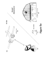
- FIG. 3 a illustrates a front angular perspective of a second REVLAR UAV configuration on the ground
- FIG. 3 b illustrates a front angular perspective of the second REVLAR UAV configuration in a first transitional phase
- FIG. 3 c illustrates a front angular perspective of the second REVLAR UAV configuration in a second transitional phase
- FIG. 3 d illustrates a front angular perspective of the second REVLAR UAV configuration in flight
- FIG. 4 a illustrates a front angular perspective of a third REVLAR UAV configuration on the ground
- FIG. 4 b illustrates a front angular perspective of the third REVLAR UAV configuration in a first transitional phase
- FIG. 4 c illustrates a front angular perspective of the third REVLAR UAV configuration in a second transitional phase
- FIG. 4 d illustrates a front angular perspective of the third REVLAR UAV configuration in flight
- FIG. 5 a illustrates an exemplary avionics system diagram for controlling a REVLAR UAV
- FIG. 5 b illustrates an exemplary component diagram of the avionics system diagram of FIG. 5 a.
- An objective of the present application is to provide a tier 2-sized long-endurance Robust Efficient Vertical Launch and Recovery (REVLAR) UAV, a form of VTOL UAV. Additionally, the present application shall illustrate how a design may be scaled and shall identify exemplary size, weight, and endurance limits for a REVLAR UAV. Particular attention shall be paid to control strategies, especially in the VTOL mode, and associated transition to long-endurance flight. While the techniques and subject matter of the present disclosure may be described in relation to USAF Tier 2 UAVs, said techniques and subject matter may be readily applied to UAVs from the other USAF UAV tiers. For further information on the USAF tier system, see, for example, Major William W. Bierbaum's article entitled “UAV”, available at http://www.airpower.maxwell.af.mil/airchronicles/cc/uay.html.
- organic UAV deployment can eliminate the need for a centralized command center.
- the REVLAR UAVs of the present application may be readily used and deployed by personnel in the field without requiring an advanced infrastructure.
- the REVLAR UAV may even be locally controlled via a hand-held remote controller or mobile command center.
- the REVLAR UAV may be configured to be controlled from a greater distance using, for example, existing communication systems, such as, for example, L-Band, LAN, WLAN, cellular phone infrastructures, etc.
- a REVLAR UAV may even employ (i) canted wings and/or (ii) tiltwing configurations.
- Canted wings may be accomplished by integrating a hinge or other joint within the wing, thereby permitting it to flex, curve, and/or pivot in the wind. Accordingly, canted hinges allow for a UAV to avoid dynamic transition by remaining trimmed at all flight conditions, from forward flight to hovering flight.
- Canted wings may be used for a variety of purposes, including, for example, reducing the angle of attack of the wing when deflected due to gusts or other disturbances.
- a first exemplary wing is disclosed by commonly owned U.S. Patent Publication No. 2010/0213309, entitled Non-Planar Adaptive Wing Solar Aircraft, by Robert Parks (the “'309 Publication”).
- the '309 Publication discloses an aircraft having wings comprising one or more modular constituent wing panels.
- Each wing panel of the '309 Publication includes at least one hinge interface that is configured to rotationally interface with a complementary hinge interface on another wing panel.
- FIGS. 1 a and 1 b Another exemplary aircraft equipped with canted wing hinges is illustrated in FIGS. 1 a and 1 b .
- FIG. 1 a illustrates an aircraft 100 with both wings 102 a , 102 b in their normal state (i.e., forming a substantially straight wing), without interference from, for example, a wind gust.
- FIG. 1 b illustrates the aircraft 100 of FIG. 1 a with the port-side wing 102 b flexing via the canted hinge to form a canted wing in response to, for example, a wind gust. Ignoring the thrust vectoring aspect of the design, as illustrated in FIG. 1 b , the wing 102 b , while in the canted wing configuration, effectively rejects gusts by maintaining constant moment at the canted hinge point 104 , thus delivering constant lift to the aircraft 100 in the face of gusts.
- a tiltwing aircraft typically features a wing that is horizontal for conventional forward flight and rotates up for vertical takeoff and landing. It is similar to a tiltrotor design where only the propeller and engine rotate. Tiltwing aircraft are often capable of VTOL operations.
- a tiltwing design offers certain advantages in vertical flight relative to a tiltrotor. Because the slipstream from the rotor strikes the wing on its smallest dimension, the tiltwing is able to apply more of its engine power to lifting the aircraft. For comparison, the V-22 Osprey tiltrotor loses about 10% of its thrust to interference from the wings.
- the fixed wing of a tiltrotor aircraft offers a superior angle of attack—thus more lift and a shorter takeoff roll—when performing STOL/STOVL operations.
- a drawback of the tiltwing is control during hover, because the wing tilted vertically represents a large surface area for crosswinds to push.
- nominal target requirements include a 10 ft wingspan, 5 hour endurance, 70 lbs gross take-off weight, and 70 mph cruise speed.
- the REVLAR UAV should also be enabled to launch and/or recover within a cylindrical area having a 3 meter radius and at least 5 meters tall (i.e., 5 meters off the ground). For example, as the vehicle enters the landing area from about 5 meters off the ground, the REVLAR UAV should be configured to transition and land without breaching the cylindrical area. Likewise during take-off it must stay inside this cylinder until it reaches 5 meters.
- the REVLAR UAV should be able to operate safely in a confined space around people under field conditions. Accordingly, there are several potential applications for such a REVLAR UAV, including, for example, equipping it with a sensor payload for intelligence, surveillance, and reconnaissance (ISR).
- ISR intelligence, surveillance, and reconnaissance
- V-Bat An exemplary VTOL UAV that appears to meet the above nominal target requirements is MLB Company's V-Bat (“V-Bat”).
- the V-Bat is a tail-sitter aircraft having a ducted fan in a pusher configuration powered by a gasoline engine.
- the V-Bat UAV has a wingspan of 10 feet, weighs 70 pounds, can fly for up to 5 hours, and is capable of launching and recovering in an area as small as 6 ⁇ 6 meters.
- the V-Bat also has a high aspect ratio straight wing mounted far aft on the fuselage.
- V-Bat Additional advantages include its low center of gravity, the fact that the rear-mounted duct has a good moment arm with respect to center of gravity to improve control power in hover, and potential benefits in drag due to duct ingestion of the fuselage boundary layer.
- the size, weight, payload, and duration of the V-Bat make it a suitable VTOL UAV, the V-Bat still suffers from shortcomings that may be overcome by the teachings of the present application.
- a first objective is to improve the efficiency of the propulsion system and reduce the engine power and weight required for hover by introducing a ducted fan, for instance using a mixer-ejector to improve hover thrust, and using a modern efficient heavy fuel engine.
- a second objective is to implement configuration modifications that simplify and stabilize the transition between hover and wing-borne flight. Once airborne, the aircraft transitions the thrust aft until a forward airspeed sufficient to support the aircraft is reached, at which point the aircraft is wing-borne and conventional aerodynamics may take over.
- a third objective is to employ full autonomy for takeoff and landing.
- the REVLAR UAV may employ a system capable of landing the UAV, remaining on the ground for a set period, and launching again in winds without any human intervention. This may be accomplished by combining a configuration that does not require dynamic transition between hover and forward flight (that is, it has a stable trim across the velocity envelope) with full-envelope flight control laws and robust recovery procedures.
- Exemplary REVLAR UAVs and configurations capable of accomplishing vertical takeoff or landing within a minimal area will now be described in greater detail.
- Said exemplary configurations include, for example: (i) resting the REVLAR UAV on a passively retractable pogo support; (ii) using canted hinges on the wing to allow the wing tips and tail to form a tripod support; and (iii) tiltwing configuration where the fuselage may be freely rotated from the wings and engines.
- wing maybe be used throughout this application, the wing may be composed of one or more wing portions, thus, for the purposes of this application, two wing portions joined together by a fuselage or other components shall be considered a single wing.
- Aspect ratio and planform can be used to predict the aerodynamic performance of a wing.
- the aspect ratio (AR) is defined as the square of the wingspan b divided by the area S of the wing planform—this is equal to the length-to-breadth ratio for constant breadth.
- AR aspect ratio
- the REVLAR UAV 200 is illustrated resting on a passively retractable pogo support 204 .
- the pogo support may be of a fixed length or telescopic (e.g., in direction B)—as illustrated in FIGS. 2 a and 2 b .
- the REVLAR UAV 200 of FIGS. 2 a and 2 b may be appear similar to a traditional UAV having a fixed wing 206 and engines 200
- the REVLAR UAV's 200 design and aerodynamics allows the aircraft to have reduced trim drag in cruise.
- the UAV 200 may comprise one or more inlets for reducing trim drag.
- the REVLAR UAV 200 may be angled toward the sky using a predetermined stand-up angle, thereby eliminating the need for a runway.
- the REVLAR UAV's 200 stand-up angle e.g., launch angle
- the launch configuration may be referred to as an efficient tripod launch and recovery configuration. This configuration also facilitated increased stability at all velocities from zero to cruise (e.g., wingborne).
- the REVLAR UAV 200 may be equipped with, for example, twin counter-rotating engines 202 .
- REVLAR UAV 200 may utilize twin ducted fans 202 (e.g., shrouded mixer-ejector fans) mounted on either side of the fuselage 208 , bringing the center of gravity forward and allowing the incorporation of a empennage (i.e., tail assembly) for reducing trim drag during cruise and hover.
- twin ducted fans 202 e.g., shrouded mixer-ejector fans mounted on either side of the fuselage 208 , bringing the center of gravity forward and allowing the incorporation of a empennage (i.e., tail assembly) for reducing trim drag during cruise and hover.
- the propulsion system could comprise a FloDesign Inc. Fan and Mixer-Ejector combination, driven by an XRD Inc. 12 hp heavy fuel engine.
- the empennage 210 generally comprises two fixed parts, the horizontal stabilizer 210 b and the vertical stabilizer 210 a .
- the horizontal stabilizer 210 b may be used to prevent the REVLAR UAV 200 from pitching up or down.
- the rear portion of the horizontal stabilizer 210 b may employ an elevator, which is usually hinged to the horizontal stabilizer 210 b .
- an elevator is a movable airfoil that may be used to control the up-and-down motion of an aircraft's nose during wing-borne flight.
- the vertical tail structure may be divided into the vertical stabilizer 210 a and the rudder.
- the vertical stabilizer 210 a is the fixed front section and may be used to prevent the aircraft from yawing back and forth.
- the vertical stabilizer 210 a may also be used to offset the tendency of the UAV to roll in the opposite direction in which the propeller is rotating.
- the rear section of the vertical structure often includes a rudder—a movable airfoil that may be used to turn an aircraft during wing-borne flight.
- an all-moving horizontal stabilizer is sometimes referred to as a stabilator.
- an all-moving stabilizer is an aircraft control surface that combines the functions of an elevator and a horizontal stabilizer. Specifically, while most fixed-wing aircraft control pitch using a hinged horizontal flap—the elevator—attached to the back of the fixed horizontal stabilizer, some aircraft make the entire stabilizer movable. Because it involves a large moving surface, a stabilator can allow the pilot to generate greater pitching moment with little effort.
- the wing can sometimes present a problem when it is stalled (e.g., during VTOL and/or transition)—vortex shedding off the wing can be non-uniform (especially in gusts), and for a high aspect ratio wing, this can lead to wing rock. Accordingly, if it is determined, e.g., by an onboard computer or operator, that these forces cannot be stabilized with the duct vane surfaces alone, the empennage's all-moving wing tips can be implemented to counter the instability. In certain aspects, both the horizontal and vertical stabilizers may be all-moving.
- a VTOL vehicle Upon liftoff, a VTOL vehicle transitions to hover via a continuous set of trim points, reducing forward speed as more of its weight becomes supported by vectored thrust. Attitude during vertical descent is typically about 90 degrees, necessitating quaternion-based attitude control.
- the pogo support 204 may deploy from and/or re-stowed (e.g., retracted) into or alongside the fuselage 208 in the directions of motion A.
- the pogo support 204 may be spring-loaded, thereby enabling quick deployment from the fuselage 208 .
- Duct flaps may be used to provide control to smoothly rotate the vehicle forward, into a stable tripod launch and recovery configuration on the ground 212 .
- the tripod attitude and overall weight-and-balance must be such that for takeoff the duct flaps can cause the vehicle to rotate about the tail 210 and achieve a vertical attitude with the thrust well below the lift-off value.
- this transition from horizontal to vertical flight is expected to be a smooth transition through a set of trim states.
- the set of trim states may be actively stabilized. Avoiding dynamic transitions is a tenet that may be employed to increase robustness.
- the pogo 204 landing support can be re-stowed using a simple pinion mechanism that overcomes the spring loads in the deployment mechanism—this simple positive-deploy/servo stow approach is used on general aviation gear to ensure reliability, since flying with gear deployed is much safer than landing without gear deployed.
- other mechanical methods known in the art could be used to re-stow the pogo 204 inside of along side the fuselage 204 (e.g., retracted or swung). Exemplary mechanical methods may take advantage of, for example, one or more of the following gear systems; pinion, worm drives, sun and planet gears, and the like.
- FIG. 2 c and Equation 2 the diagram illustrates exemplary target requirements for a non-skittering rotation capable of launch, or takeoff.
- torque T about the pivot point is computed.
- Torque T for the vectored component of thrust must overcome the torque of the vehicle weight.
- the minimum stand-up angle ⁇ shown here assumes that thrust (T/mg) is maintained below 80% weight to prevent skittering, and the application of thrust is at the center of gravity. More specifically, T is the thrust of the engines, dt is angle that the thrust can be deflected with respect to the fuselage using flaps or other thrust-vectoring techniques, L T and L g are the distances from the pivot point on the ground to the point of thrust application and the center of gravity, respectively.
- m is the mass of the vehicle
- g is the acceleration of gravity
- ⁇ is the angle that the vehicle make with the ground.
- thrust T should be well below (for instance, 80 percent of) the weight (mg) to maintain friction at the pivot point, and the ratio L T /L g is approximately one due to the proximity of the center of gravity to the engines.
- thrust vectoring of about 30 degrees can be achieved. As illustrated by Equation 2, this results in a minimum ⁇ value (stand-up angle) of 66 degrees for the on-ground attitude of the vehicle.
- a design trade-off in determining the best overall configuration for a particular application is to understand the best landing altitude for stability on the ground, as well as ease of transition back to hover.
- the autonomous take-off phase is prone to complex ground interaction involving ‘skittering’ across the ground or otherwise accelerating in unwanted ways during transition from weight-on-skids to air.
- thrust vectoring is sufficient to rotate the vehicle to vertical while significant weight (perhaps 20% of the vehicle weight) is still supported by the tail, these effects can be virtually eliminated.
- Higher attitudes require either less thrust (T) or less thrust vectoring (dt) to rotate based on Equation 2, but provide less resistance to tip-over from gusts.
- an example stand-up angle value between 45 and 90 degrees may be suitable; more preferably between 60 and 80 degrees, and most preferably between 66 and 75 degrees.
- a REVLAR UAV 300 may be equipped with canted hinges 308 on the wings 306 , thereby enabling the wing tips, or distal ends of the wing structure, and tail 312 to form a tripod launch and recovery configuration.
- the REVLAR UAV 300 of FIGS. 3 a -3 d is otherwise substantially similar to the REVLAR UAV of FIGS. 2 a -2 c . Accordingly, the same propulsion techniques, airfoil designs, angle calculations, techniques, and the like make be applied.
- the distal ends of the REVLAR UAV's 300 wing 306 may include retractable pogo supports 304 to widen the UAV's 300 stance on the ground and to increase the stand-up angle without requiring a longer wing.
- pogo supports 304 may be deployed from the wing tips (e.g., distal ends), so that the fully folded wing plus pogo supports 304 form a tripod launch and recovery configuration when combined with the empennage 312 .
- FIGS. 3 a through 3 d illustrate four exemplary wing-droop settings encountered when transitioning from ground to wing-borne flight.
- FIG. 3 a illustrates the REVLAR UAV 300 on the ground with the wing 306 in a canted wing configuration. This may be accomplished by bending the canted hinges 308 to a predefined maximum bend angle. As illustrated, the resulting REVLAR UAV 300 has a wide stance and low center of pressure on the ground—both characteristics assist in preventing the REVLAR UAV 300 from tipping over. As previously mentioned, the stance may be widened by including retractable pogo supports 304 . The retractable pogo supports 304 also provide the added benefit of increasing the stand-up angle ⁇ without requiring that the wing 306 be lengthened. As in the REVLAR UAV 200 of FIG. 2 b , depending on the design needs of the REVLAR UAV 300 , the retractable pogo support 304 may be of a fixed length or telescopic.
- the REVLAR UAV 300 is shown as having entered the second phase of the take-off transition—the wing's 306 canted hinges 308 have begun to straighten out.
- the retractable pogo supports 304 have been re-stowed (e.g., retracted) into the wing 306 to avoid, for instance, unnecessary drag.
- the pogo supports 304 may be retracted using, for example, a pinion mechanism that overcomes the spring loads in the deployment mechanism.
- electromagnets, solenoids, or other similar means may even be used to provide a retracting pulling force.
- the outboard wing portions may be maintained at a low angle of attack (alpha) during the steady-state transition to hover.
- FIG. 3 c illustrates the third phase of the take-off transition where the canted wing 306 has continued to straighten out via the cant hinges 308 as the REVLAR UAV 300 gains altitude.
- FIG. 3 d illustrates the fourth and final phase where the wing 306 and cant hinges 308 have fully extended and are said to have been straightened out. In other words, the wing 306 has transformed to a substantially straight wing configuration. At this point, the REVLAR UAV 300 may enter a horizontal, wing-borne state.
- alpha refers to the angle of attack—the angle between a reference line on a lifting body (often the chord line of an airfoil) and the vector representing the relative motion between the lifting body and the air/fluid through which it is moving.
- wing 306 which are immediately outboard of the engines (e.g., propulsors) 302 , are used to overcome these difficulties.
- the cant (or bend) in the hinge 308 causes the angle of attack of the outboard section of the wing 306 to be reduced.
- FIGS. 3 a -3 d at each vehicle attitude there exists a hinge bend angle that brings the wing into a low-alpha, lift producing configuration. Together with the all-moving horizontal tail empennage, this approach enables the REVLAR UAV 300 to achieve trim while minimizing wing stall down to very low speed.
- the canted wing geometry can be used for active gust load alleviation in up-and-away flight.
- the pogo supports 304 may be deployed from the wing 306 at the tips as described and illustrated in FIG. 3 a.
- canted hinges 308 in a wing 306 assists in avoiding the necessity for a dynamic transition (e.g., untrimmed flight requiring precise maneuvering) during the takeoff of a REVLAR UAV, while also providing a stable base for the REVLAR UAV ‘tail-sitter’ take-off and landing configuration show in FIG. 3 a .
- Advantageous features of a REVLAR UAV 300 having canted hinges include, for example: (1) VTOL takeoff can be accomplished by rotating the vehicle about the tail boom/ground contact point using thrust vectoring while transitioning from stationary to vertical flight; (2) on the ground, the canted hinge-pogo design provides a broad, stable base with low center of pressure to help prevent tip over; (3) during landing, outboard panels remain at low angle of attack, providing trim at low speed.
- FIGS. 4 a -4 d A third REVLAR UAV configuration involves a modification of the free wing concept, and is shown in FIGS. 4 a -4 d —this type of wing configuration being more commonly known as tiltwing.
- FIGS. 4 a through 4 d a third REVLAR configuration is shown that uses a form of tiltwing that involves rotating the fuselage 404 freely from the wings 406 and engines 402 to enable ground recovery and re-launch.
- the concept of operations are substantially the same as the REVLAR UAV of the previous examples, except for lack of pogo and launch and recovery.
- a mechanical latch device is released to enable the tiltwing configuration (e.g., the ability to transition from a vertical configuration to a horizontal configuration).
- the wings 406 are in the vertical configuration.
- the nose end of the fuselage begins to lift off the ground 408 while the tail end initially remains on or near the ground 408 , thereby causing to fuselage 404 to be non-parallel to the ground 408 .
- a second phase of takeoff as the engine 402 thrust continues to increase and the wing 406 begins to transition from the vertical configuration to the horizontal configuration (e.g., the fuselage 404 freely rotates) until the fuselage 404 has achieved a predetermined stand-up angle.
- the standup angle may be calculated using the methods of FIG. 2 c or the standup angle may simple be substantially vertical to the ground 408 (e.g., ⁇ 90 degrees).
- the wings are nearing the horizontal configuration.
- the wing 406 had achieved the horizontal configuration and the aircraft is capable of wingborne flight. Once the wings are in their horizontal configuration, the mechanical latch device is enabled, thereby locking the wings in the horizontal configuration and preventing the fuselage 404 from freely rotating.
- the REVLAR UAV 400 performs substantially the same phase sequence as the launching procedure, but in reverse order. Specifically, when the REVLAR UAV 400 contacts the ground 408 , whether vertically or at an angle, and as thrust is reduced, the mechanical latch device is released, thereby re-enabling the tiltwing configuration and allowing the fuselage 404 to rotate with respect to the wings 406 . Thrust continues to reduce to a value required to support the wing structure 406 , but not the fuselage 404 . At this point, the wings 406 begin to drop, and the fuselage 404 rotates or slides out from under the wings 406 . The fuselage 404 at the completion of touchdown is horizontal to the ground 408 , but the wings 406 and engines 402 remain oriented vertically.
- the tiltwing configuration includes a mechanism for mechanically unlatching-latching that will lock the wing positively in place during takeoff/wingborne flight, and allow the wing to unlock during landing or transition.
- a tapered pin that is actuated to protrude from the fuselage.
- the tapered pin may be configured to engage a hole in the root spar of the wing that would both align the wing with the fuselage and hold it in place.
- Other mechanisms are possible, including, for example, direct servo-drive of the wing tilt axis, a spring-loaded latch mounted on the wing which engages a release mechanism in the fuselage.
- FIG. 4 a illustrates the REVLAR UAV 400 on the ground, in a take-off position where the portions of the wings 406 between the fuselage 404 and the distal ends of the wings 406 are vertically oriented with respect to the fuselage.
- the pivoting wing portions may be pivotally coupled either to the remaining portion of the wing, or directly to a fuselage using one or more known techniques.
- a rotating shaft may be employed.
- a rotating shaft that is co-located with the main spar may be employed.
- the shaft may be rigidly and/or internally mounted to either the outboard or inboard portion of the wing or the fuselage, and rotating on roller bearings on the other portion.
- the REVLAR UAV 400 has an extremely low center of gravity and is laying substantially flat on the ground, thereby virtually eliminating any risk of the REVLAR UAV 400 from tipping over.
- the fuselage 404 Prior to liftoff, the fuselage 404 is substantially perpendicular to the wings 406 and the pivotable combination of engine 402 and wing portion are vertical—pointing upward, toward the sky.
- FIG. 4 b the second phase of the take-off transition is illustrated.
- the engines 402 and wing portions 406 begin to vertically lift off of the ground 408 , causing the nose portion of the fuselage 404 to point upward, wherein the tail 412 section is still in contact with, or closer to, the ground 408 .
- FIG. 4 c illustrates the third phase of the take-off transition where the fuselage 404 has continued to pivot and is now almost parallel with the wings' 406 direction and the direction of engine thrust. In other words, the outer portions of the wings 406 are approaching the horizontal configuration.
- FIG. 4 d illustrates the fourth and final phase where the wings 406 portions have fully pivoted and are horizontal with respect to the fuselage 404 ; in other words, the wing is substantially parallel with the fuselage 404 .
- the REVLAR UAV 400 has achieved wing-borne state.
- the weight of the REVLAR UAV should be about the same, regardless of configuration. Specifically, the weight breakdown of an exemplary REVLAR UAV is provided in Table 1 below.
- FIGS. 5 a and 5 b illustrate an exemplary avionics system 500 component diagram for controlling a REVLAR UAV 502 .
- an exemplary avionics system 500 generally comprises three primary components: a REVLAR UAV 502 ; a ground control station 504 ; and a ground service module 506 .
- the REVLAR UAV 502 may include any one of the UAVs disclosed in FIGS. 2 a -4 d .
- the REVLAR UAV 502 typically includes an on-board vehicle computer 524 that is responsible for controlling the various aircraft components and functions.
- the vehicle computer 524 may be communicatively coupled with a remote input/output unit 530 (e.g., Power DNA Cube—DNA-PPC5), a Inertial Navigation System (INS) 522 (e.g, Raytheon Advanced Protection Technology Receiver (RAPToR)) that is communicatively coupled with an inertial measurement unit 526 and GPS receiver, a user interface panel 532 , an on-board memory device 560 (e.g., hard drive, flash memory, or the like), or other services 520 .
- INS Inertial Navigation System
- RPToR Raytheon Advanced Protection Technology Receiver
- the remote input/output unit 530 may be communicatively coupled with Microair UAV Transponder 534 , engine control unit (ECU) 536 , Power Switching 538 , Power System Status 540 and an Airdata/Mag unit 542 .
- the remote input/output unit 530 may be communicatively coupled with the user interface panel 532 for maintenance and with a payload 528 (e.g., SMEP DRS) for control.
- a payload 528 e.g., SMEP DRS
- the REVLAR UAV 502 further comprises an air communication link 510 enabled to transmit (TX) and receive (RX) power using one or more antennas (e.g., top and bottom) via a circulator 516 , LNE 512 and RFE 514 .
- the REVLAR UAV may be equipped with a traditional ISR surveillance payload.
- the REVLAR UAV 502 may be equipped with one or more cameras 508 , audio devices, and the like. Any video, or other data, collected by the REVLAR UAV 502 may be wirelessly communicated to the ground control station 504 in real time.
- the REVLAR UAV 502 may be further equipped to store said video and data to the on-board memory device 560 . If the REVLAR UAV 502 is operated in an unfriendly zone, it may be advantageous to implement a data self-destruction protocol.
- the REVLAR UAV 502 may be programmed to erase, or otherwise destroy, the on-board memory device 560 if the REVLAR UAV 502 determines that it may have fallen into an enemy's possession. For example, the REVLAR UAV's 502 on-board memory device 560 may automatically erase upon touching down in a location outside of a predefined radius from the launch area, based on GPS calculations, or if a crash is detected, e.g., based upon a sudden impact.
- the ground control station 504 is used to wirelessly control the operation of one or more REVLAR UAVs 502 , including, at least, launch, recovery, and flight.
- the ground control station 504 may be a portable station such as, for example, a mobile command center, remote controller, and the like.
- a portable ground control station 504 may be advantageous in that it enables UAV 502 deployment from nearly any location with minimal preparation.
- the ground control station 504 may be stationary, such as those found in substantially permanent structures and buildings, whether local, or remotely controlled from a distance via a communication network (e.g., the internet, wireless phone network, etc.).
- a communication network e.g., the internet, wireless phone network, etc.
- An exemplary ground control station 504 may comprise a vehicle control station 552 to a ground communication link 550 for communication with a REVLAR UAV 502 .
- An exemplary ground communication link 550 may include the EnerLinksIIITM Intelligence, Surveillance and Reconnaissance (ISR) system, available form ViaSat, Inc. at http://www.viasat.com/government-communications/isr-data-links/enerlinks.
- the vehicle control station 552 which is communicatively coupled to the exemplary ground communication link 550 , may include one or more user interface devices, thereby allowing a person to operate and monitor the REVLAR UAV 502 from the ground control station 504 .
- Exemplary interface devices may include, for example, one or more joysticks, throttles, buttons, and any other controllers that may be useful in controlled flight and/or surveillance.
- the vehicle control station 552 may also include one or more audio/visual devices, thereby permitting the user to monitor the REVLAR UAV 502 from a distance.
- the video signal from the camera 508 or any other data, including location may be wirelessly communicated to the ground control station and displayed using said audio/visual devices.
- An exemplary Vehicle Control Station 552 may employ or incorporate CDL Systems Ltd.'s VCS-4586.
- VCS-4586 For additional information on the VCS-4586, see, for example, CDL Systems Ltd website at http://www.cdlsystems.com/index.php/vcs4586.
- the ground communication link 550 may communicate with the REVLAR UAV 502 using four or more radio interface modules 546 and pointing systems 544 .
- the ground control station 504 preferably communicates with the REVLAR UAV, using L band or another spectrum reserved for military use.
- L band refers to four different bands of the electromagnetic spectrum: 40 to 60 GHz (NATO), 1 to 2 GHz (IEEE), 1565 nm to 1625 nm (optical), and around 3.5 micrometers (infrared astronomy). In the United States and overseas territories, the L band is generally held by the military for telemetry.
- a real-time kinematic (RTK) system 548 may also be coupled to the ground communication link 550 to provide positioning information in cooperation with a GPS transmitter and antenna.
- RTK satellite navigation is a technique used for land and hydrographic survey.
- RTK technology may be based on the use of carrier phase measurements of the GPS, Globalnaya navigatsionnaya sputnikovaya ista (GLONASS) and/or Galileo signals where a single reference station provides the real-time corrections, providing up to centimeter-level accuracy.
- the ground service module 506 is primarily used for ground maintenance.
- Ground maintenance may include, for example, updating the REVLAR UAV's 502 software, firmware, diagnostics, battery charging, and the like.
- the ground service module 506 may be portable or stationary, depending on the needs of the particular user. However, because the ground service module 506 is often connected to the REVLAR UAV 502 using a wired connection, the ground service module 506 is preferably accessible to the launch and/or recovery location.
- the ground service module 506 generally comprises a battery charger 554 , AC-DC converter 556 , and ENET switch 558 .
- the AC-DC converter 556 is enabled to receive AC current from a ground power source (e.g., 120 VAC) and covert it to a usable DC power (e.g., 28 volts).
- the AC-DC converter 556 may be used to provide power to the REVLAR UAV 502 and/or the battery charger 554 .
- the REVLAR UAV 502 is typically connected to the ground service module 504 via a wired connection, such as a cable bundle or umbilical. This wired connection may be used to carry both current and data signals.
- One or more switches or relays may be used to selectively connect the battery charger 554 and AC-DC converter 556 to the REVLAR UAV 502 .
- the REVLAR UAV 502 may receive power directly from the AC-DC converter 556 or use the battery charger 554 to charge any on-board batteries.
- the ENET switch 558 may be used for maintenance (e.g., diagnostics) and other data transfers (e.g., software updates or backup).
- avionics systems may be specifically designed for use in the above REVLAR configurations
- existing avionics systems may be adapted for REVLAR configurations.
- existing avionics systems such as those used for the Aurora GE-50, GE-80, Excalibur, Orion, Vulture, and Skate, might be adapted for use with a REVLAR UAV.
- Avionics components in these architectures may include the flight control system (GPS-INS and flight computer), communications, ground servicing equipment, and ground control station (GCS).
- GCS ground control station
- Many of Aurora's systems use the TRL 9 VCS-4586 Vehicle Control Station software from CDL systems for the GCS, and employ an on-board vehicle management computer that houses a STANAG-4586 compliant Vehicle Specific Module (VSM).
- VSM Vehicle Specific Module
- Lower cost implementations such as Skate use Aurora's miniature Autopilot, which has been adapted to a number of low-cost flight test efforts, and is part of Skate's military-ready product.
- Verifying the control strategy for the REVLAR vehicle a medium fidelity simulation can adequately predict behavior in the regime from hover to low-speed flight. Trim, stability, and controllability properties may use the resulting vehicle aerodynamics, combined with test stand-verified models of ducted fan performance and control effectors in duct flows.
- Torque commands from the vehicle control laws are subsequently passed through control allocation software that performs control surface mixing in the face of saturation and nonlinearities.
- nonlinearities arise from kinematic effects at high angles of attack, large thrust vectoring angles, and from the duct vanes themselves. Saturations are a primary concern during hover-to-land operations; winds typically cause saturation in the axis, which must turn the vehicle into the wind to maintain position.
- Trim calculations, linearizations, and control law designs should be calculated at a number of representative conditions across the flight envelope to demonstrate the feasibility of robust control, for the down-selected REVLAR configuration. For instance, steady winds from various headings, superimposed with Dryden gust spectra, may be used to demonstrate the robustness of the vehicle-controller combination, the adequacy of the control power, and the repeatability of recovery. Transition from air to ground may be modeled using ground-interaction approaches developed for other auto-land programs for VTOL vehicles. Controlled rotation (vehicle weight balanced at all times) and ‘gravity-assisted’ rotation (vehicle allowed to accelerate about the touchdown point) may also be applied to tripod landing.
- the first method is to descend quickly.
- Certain aircraft may be configured to execute a deep stall to affect a precipitous recovery to a relatively small area. While this approach is not viable for vehicles much larger than the REVLAR, because this maneuver can cause catastrophic damage on impact, a controlled vertical descent at 5 to 10 meters per second (depending on the prevailing winds and gusts), terminating in a hard, positive landing, should be robust and repeatable without incurring undue wear-and-tear on the vehicle.
- the second method is to measure and reject winds and gusts. While this approach is more complicated in that it requires additional sensors, this approach provides greater accuracy. For instance, in very severe wind and gust situations, not only will alpha and/or beta measurements be extremely useful, but in some cases distributed measurement, e.g., left vs. right wing, will significantly improve accuracy and effectiveness.
- Exemplary sensors suitable for incorporation are available through Aeroprobe Corporation. For additional information, see, for example, Aeroprobe Corporation's website at http://www.aeroprobe.com and their line of air data probes, available at http://www.aeroprobe.com/uploads/Air-Data-Applications-for-web.pdf.
Abstract
Description
| TABLE 1 | |||
| Structure (20% GTOW) | 14 | ||
| Payload | 5 | ||
| Twin Ducted Fans | 10 | ||
| XRDi 12 HP Engine | 16 | ||
| Three Gearboxes | 11 | ||
| Fuel | 14 | ||
| Total | 70 | ||
Claims (22)
Priority Applications (1)
| Application Number | Priority Date | Filing Date | Title |
|---|---|---|---|
| US14/507,198 US9540101B2 (en) | 2012-02-15 | 2014-10-06 | System, apparatus and method for long endurance vertical takeoff and landing vehicle |
Applications Claiming Priority (2)
| Application Number | Priority Date | Filing Date | Title |
|---|---|---|---|
| US13/397,569 US20130206921A1 (en) | 2012-02-15 | 2012-02-15 | System, apparatus and method for long endurance vertical takeoff and landing vehicle |
| US14/507,198 US9540101B2 (en) | 2012-02-15 | 2014-10-06 | System, apparatus and method for long endurance vertical takeoff and landing vehicle |
Related Parent Applications (1)
| Application Number | Title | Priority Date | Filing Date |
|---|---|---|---|
| US13/397,569 Division US20130206921A1 (en) | 2012-02-15 | 2012-02-15 | System, apparatus and method for long endurance vertical takeoff and landing vehicle |
Publications (2)
| Publication Number | Publication Date |
|---|---|
| US20150336666A1 US20150336666A1 (en) | 2015-11-26 |
| US9540101B2 true US9540101B2 (en) | 2017-01-10 |
Family
ID=48944819
Family Applications (4)
| Application Number | Title | Priority Date | Filing Date |
|---|---|---|---|
| US13/397,569 Abandoned US20130206921A1 (en) | 2012-02-15 | 2012-02-15 | System, apparatus and method for long endurance vertical takeoff and landing vehicle |
| US14/507,198 Active US9540101B2 (en) | 2012-02-15 | 2014-10-06 | System, apparatus and method for long endurance vertical takeoff and landing vehicle |
| US14/507,313 Active US9682774B2 (en) | 2012-02-15 | 2014-10-06 | System, apparatus and method for long endurance vertical takeoff and landing vehicle |
| US14/507,228 Abandoned US20150021430A1 (en) | 2012-02-15 | 2014-10-06 | System, apparatus and method for long endurance vertical takeoff and landing vehicle |
Family Applications Before (1)
| Application Number | Title | Priority Date | Filing Date |
|---|---|---|---|
| US13/397,569 Abandoned US20130206921A1 (en) | 2012-02-15 | 2012-02-15 | System, apparatus and method for long endurance vertical takeoff and landing vehicle |
Family Applications After (2)
| Application Number | Title | Priority Date | Filing Date |
|---|---|---|---|
| US14/507,313 Active US9682774B2 (en) | 2012-02-15 | 2014-10-06 | System, apparatus and method for long endurance vertical takeoff and landing vehicle |
| US14/507,228 Abandoned US20150021430A1 (en) | 2012-02-15 | 2014-10-06 | System, apparatus and method for long endurance vertical takeoff and landing vehicle |
Country Status (1)
| Country | Link |
|---|---|
| US (4) | US20130206921A1 (en) |
Cited By (13)
| Publication number | Priority date | Publication date | Assignee | Title |
|---|---|---|---|---|
| US20180086462A1 (en) * | 2016-09-28 | 2018-03-29 | Airbus Defence and Space GmbH | Fixed-wing aircraft and method for operating a fixed-wing aircraft |
| US10234872B2 (en) * | 2016-09-05 | 2019-03-19 | Zerotech (Chongqing) Intelligence Technc | Method and apparatus for launching unmanned aerial vehicle and unmanned aerial vehicle incorporating the same |
| US10464668B2 (en) | 2015-09-02 | 2019-11-05 | Jetoptera, Inc. | Configuration for vertical take-off and landing system for aerial vehicles |
| US10526065B2 (en) * | 2016-04-26 | 2020-01-07 | Airbus Helicopters | Drone having at least three lift and propulsion rotors |
| US10562623B1 (en) * | 2016-10-21 | 2020-02-18 | Birdseyeview Aerobotics, Llc | Remotely controlled VTOL aircraft |
| US10815008B2 (en) * | 2017-07-27 | 2020-10-27 | Bell Helicopter Textron Inc. | Lift propulsion module for a tiltrotor aircraft |
| US10875658B2 (en) | 2015-09-02 | 2020-12-29 | Jetoptera, Inc. | Ejector and airfoil configurations |
| US11001378B2 (en) | 2016-08-08 | 2021-05-11 | Jetoptera, Inc. | Configuration for vertical take-off and landing system for aerial vehicles |
| US11148801B2 (en) | 2017-06-27 | 2021-10-19 | Jetoptera, Inc. | Configuration for vertical take-off and landing system for aerial vehicles |
| US11260972B2 (en) * | 2018-01-24 | 2022-03-01 | Arizona Board Of Regents On Behalf Of Arizona State University | Systems and methods for a foldable unmanned aerial vehicle having a laminate structure |
| WO2022095207A1 (en) * | 2020-11-09 | 2022-05-12 | 深圳市大疆创新科技有限公司 | Tripod and unmanned aerial vehicle |
| US11591076B2 (en) * | 2019-06-26 | 2023-02-28 | Toyota Motor Engineering & Manufacturing North America, Inc. | Inflatable drone with shape memory alloy wires |
| US11603197B2 (en) * | 2016-09-12 | 2023-03-14 | Israel Aerospace Industries Ltd. | Modular vehicle system |
Families Citing this family (74)
| Publication number | Priority date | Publication date | Assignee | Title |
|---|---|---|---|---|
| WO2013105926A1 (en) | 2011-03-22 | 2013-07-18 | Aerovironment Inc. | Invertible aircraft |
| US20130233964A1 (en) * | 2012-03-07 | 2013-09-12 | Aurora Flight Sciences Corporation | Tethered aerial system for data gathering |
| US9384668B2 (en) | 2012-05-09 | 2016-07-05 | Singularity University | Transportation using network of unmanned aerial vehicles |
| US20140025230A1 (en) * | 2012-07-17 | 2014-01-23 | Elwha LLC, a limited liability company of the State of Delaware | Unmanned device interaction methods and systems |
| US20140024999A1 (en) * | 2012-07-17 | 2014-01-23 | Elwha LLC, a limited liability company of the State of Delaware | Unmanned device utilization methods and systems |
| CA2822665C (en) * | 2012-07-31 | 2018-07-17 | Gabor Devenyi | Aircraft wing having continuously rotating wing tips |
| US9085354B1 (en) | 2013-04-23 | 2015-07-21 | Google Inc. | Systems and methods for vertical takeoff and/or landing |
| US9428257B2 (en) | 2013-09-18 | 2016-08-30 | William Edmund Nelson | Extended endurance air vehicle |
| US9567088B2 (en) | 2013-10-15 | 2017-02-14 | Swift Engineering, Inc. | Vertical take-off and landing aircraft |
| US9174732B2 (en) * | 2013-12-30 | 2015-11-03 | Google Inc. | Methods and systems for transitioning an aerial vehicle between crosswind flight and hover flight |
| EP3116781B1 (en) | 2014-03-13 | 2019-05-22 | Endurant Systems LLC | Direct current power supply system for a multi-rotor vehicle |
| US9481457B2 (en) * | 2014-04-02 | 2016-11-01 | Sikorsky Aircraft Corporation | Vertical take-off and landing aircraft with variable wing geometry |
| US10011350B2 (en) * | 2014-05-20 | 2018-07-03 | Sikorsky Aircraft Corporation | Vertical take-off and landing drag rudder |
| US9971354B2 (en) * | 2014-06-10 | 2018-05-15 | Sikorsky Aircraft Corporation | Tail-sitter flight management system |
| US9879655B1 (en) * | 2014-06-30 | 2018-01-30 | X Development Llc | Attachment apparatus for an aerial vehicle |
| US9550567B1 (en) | 2014-10-27 | 2017-01-24 | Amazon Technologies, Inc. | In-flight reconfigurable hybrid unmanned aerial vehicle |
| US9731816B2 (en) * | 2014-12-08 | 2017-08-15 | The Boeing Company | Multi-position landing gear |
| FR3030451A1 (en) * | 2014-12-22 | 2016-06-24 | Parrot | ACCESSORY TO MAKE AN AMPHIBIOUS DRONE |
| US20160236775A1 (en) * | 2015-02-18 | 2016-08-18 | Siniger LLC | Vertical takeoff and landing aircraft |
| US10343774B2 (en) * | 2015-07-14 | 2019-07-09 | Jeremy Duque | Quad rotor aircraft with fixed wing and variable tail surfaces |
| US20170021924A1 (en) * | 2015-07-23 | 2017-01-26 | Sikorsky Aircraft Corporation | Control system and strategy for tail sitter |
| RU2599270C2 (en) * | 2015-08-20 | 2016-10-10 | Дмитрий Дмитриевич Кожевников | Cruise missile-surface effect craft (cmsec) |
| WO2017042291A1 (en) * | 2015-09-08 | 2017-03-16 | Swiss Aerobotics Ag | Aircraft for transport and delivery of payloads |
| US10513332B2 (en) * | 2015-10-05 | 2019-12-24 | Sikorsky Aircraft Corporation | Tiltwing aircraft |
| WO2017131834A2 (en) * | 2015-11-07 | 2017-08-03 | Renteria Joseph Raymond | Pivoting wing system for vtol aircraft |
| WO2017083406A1 (en) * | 2015-11-10 | 2017-05-18 | Matternet, Inc. | Methods and systems for transportation using unmanned aerial vehicles |
| US9630713B1 (en) | 2015-12-17 | 2017-04-25 | Qualcomm Incorporated | Unmanned aerial vehicle with adjustable aiming component |
| USD859280S1 (en) * | 2015-12-18 | 2019-09-10 | Leonardo S.P.A. | Combined aircraft and scale model |
| US10926874B2 (en) * | 2016-01-15 | 2021-02-23 | Aurora Flight Sciences Corporation | Hybrid propulsion vertical take-off and landing aircraft |
| JP6590173B2 (en) * | 2016-03-22 | 2019-10-16 | 株式会社Ihi | Vertical take-off and landing aircraft |
| US9821909B2 (en) * | 2016-04-05 | 2017-11-21 | Swift Engineering, Inc. | Rotating wing assemblies for tailsitter aircraft |
| US9975632B2 (en) | 2016-04-08 | 2018-05-22 | Drona, LLC | Aerial vehicle system |
| RU2656934C2 (en) * | 2016-04-25 | 2018-06-07 | Андрей Иванович Глухов | Method of vertical displacement and aircraft hovering in air |
| USD800843S1 (en) * | 2016-09-01 | 2017-10-24 | Unmanned Innovation Inc. | Airframe |
| CN106347657B (en) * | 2016-09-30 | 2019-02-19 | 扬州锐德飞科技有限公司 | A kind of unmanned plane and its working method for geography information exploration |
| USD854967S1 (en) * | 2016-10-25 | 2019-07-30 | Beijing Jingdong Shangke Information Technology Co., Ltd. | Unmanned aerial vehicle |
| USD831124S1 (en) * | 2016-11-16 | 2018-10-16 | X Development Llc | Wind energy kite tail |
| USD816547S1 (en) * | 2016-12-09 | 2018-05-01 | Beijing Jingdong Shangke Information Technology Co., Ltd. | Drone |
| CA3057560A1 (en) * | 2017-03-22 | 2019-09-27 | DZYNE Technologies Incorporated | Vertical takeoff and landing aircraft |
| USD822579S1 (en) * | 2017-04-24 | 2018-07-10 | AFS-DV VTOL Technologies Corporation | Aircraft |
| US10252798B2 (en) * | 2017-04-27 | 2019-04-09 | Pterodynamics | Vertical takeoff and landing airframe |
| CN107176286B (en) * | 2017-05-16 | 2023-08-22 | 华南理工大学 | Double-duct fan power system-based foldable fixed wing vertical take-off and landing unmanned aerial vehicle |
| TWI620688B (en) * | 2017-05-19 | 2018-04-11 | 林瑤章 | Lightweightaircraft |
| WO2018222388A1 (en) * | 2017-05-31 | 2018-12-06 | The Regents Of The University Of California | Tilt-frame uav for agricultural air sampling with a propeller-thrust-governing system that facilitates vtol capability |
| EP3632796B1 (en) | 2017-06-04 | 2021-10-20 | Aeronext Inc. | Aerial vehicle |
| WO2019147196A2 (en) * | 2017-07-06 | 2019-08-01 | Istanbul Teknik Universitesi | Autonomous unmanned aerial vehicle |
| US10822101B2 (en) | 2017-07-21 | 2020-11-03 | General Electric Company | Vertical takeoff and landing aircraft having a forward thrust propulsor |
| USD843889S1 (en) * | 2017-10-04 | 2019-03-26 | Elroy Air, Inc. | Unmanned cargo delivery aircraft |
| USD852092S1 (en) * | 2017-10-12 | 2019-06-25 | Wing Aviation Llc | Unmanned aerial vehicle |
| RU2681464C1 (en) * | 2017-11-07 | 2019-03-06 | Александр Викторович Атаманов | Small-sized vertical take-off/landing aircraft with an increased flight distance |
| GB2568737A (en) * | 2017-11-27 | 2019-05-29 | Airbus Operations Ltd | A curved interface between an outer end of a wing and a moveable wing tip device |
| CN108263603B (en) * | 2018-01-25 | 2020-12-01 | 杨曙铭 | Four rotor unmanned aerial vehicle take-off power-assisted devices |
| CN108313281B (en) * | 2018-03-19 | 2021-07-16 | 西北工业大学 | Variable-configuration unmanned aerial vehicle |
| DE102018116167B4 (en) | 2018-07-04 | 2024-03-21 | Dr. Ing. H.C. F. Porsche Aktiengesellschaft | aircraft |
| GB201811400D0 (en) * | 2018-07-12 | 2018-08-29 | Rolls Royce Plc | VTOL aircraft |
| US11046416B2 (en) * | 2018-08-03 | 2021-06-29 | Aurora Flight Sciences Corporation | Combination flight and ground apparatus for a vehicle |
| US20200079492A1 (en) | 2018-09-11 | 2020-03-12 | Swift Engineering, Inc. | Systems and methods for aerodynamic deployment of wing structures |
| US11079760B2 (en) * | 2018-11-28 | 2021-08-03 | The Boeing Company | Methods for maintaining difficult-to-access structures using unmanned aerial vehicles |
| CN109606609A (en) * | 2018-12-29 | 2019-04-12 | 成都纵横大鹏无人机科技有限公司 | A kind of unmanned plane |
| US11091258B2 (en) | 2019-06-14 | 2021-08-17 | Bell Textron Inc. | VTOL aircraft with tilting rotors and tilting ducted fans |
| US11097838B2 (en) * | 2019-06-14 | 2021-08-24 | Bell Textron Inc. | Duct with optimized horizontal stator shape |
| JP7153351B2 (en) * | 2019-08-02 | 2022-10-14 | 株式会社エアロネクスト | Airplane flight method |
| JP7438523B2 (en) * | 2019-08-02 | 2024-02-27 | 株式会社エアロネクスト | Aircraft and flight methods for aircraft |
| WO2021053829A1 (en) * | 2019-09-20 | 2021-03-25 | 株式会社エアロネクスト | Flying body |
| US11106221B1 (en) | 2019-11-25 | 2021-08-31 | Kitty Hawk Corporation | Multicopter with self-adjusting rotors |
| US10913547B1 (en) | 2020-03-31 | 2021-02-09 | Kitty Hawk Corporation | Charging station for self-balancing multicopter |
| US10926654B1 (en) | 2020-03-31 | 2021-02-23 | Kitty Hawk Corporation | Electric vertical take-off and landing vehicle with wind turbine |
| EP3901034A1 (en) * | 2020-04-20 | 2021-10-27 | Air Taxi Science and Technology Company Limited | Compound rotor aircraft |
| IL298177A (en) * | 2020-05-14 | 2023-01-01 | Pterodynamics Inc | Control of aircraft with vertical take-off and landing capabilities |
| US20230331408A1 (en) * | 2020-05-19 | 2023-10-19 | Aigen, Inc. | Weather-resistant unmanned aerial vehicles, and associated systems and methods |
| EP4178857A1 (en) * | 2020-07-10 | 2023-05-17 | HW Aviation AG | Hybrid drone for landing on vertical structures |
| FR3113399B1 (en) * | 2020-08-13 | 2023-03-31 | Fleasy | Aerodynamic device for aircraft and aircraft fitted with such a device |
| WO2022245474A2 (en) * | 2021-04-26 | 2022-11-24 | Aigen Inc. | Walking vtol drone and related systems and methods |
| CN113486438B (en) * | 2021-05-18 | 2023-03-28 | 中国人民解放军95840部队 | Stall-tail-spin real-time flight simulation modeling and stall-tail-spin flight simulation method |
Citations (62)
| Publication number | Priority date | Publication date | Assignee | Title |
|---|---|---|---|---|
| US1875267A (en) | 1932-08-30 | Umberto savoja | ||
| US2095734A (en) * | 1933-01-16 | 1937-10-12 | Dornier Claude | Rotor flying machine |
| US2481379A (en) * | 1945-07-26 | 1949-09-06 | Charles H Zimmerman | Aircraft having extensible landing gear positionable for horizontal and vertical take-off |
| US2575647A (en) * | 1948-01-13 | 1951-11-20 | William R Winslow | Aircraft landing gear |
| US2578578A (en) * | 1946-03-04 | 1951-12-11 | Myers George Francis | Convertible aircraft landing gear |
| US2622826A (en) * | 1946-06-27 | 1952-12-23 | Gen Electric | Helicopter-airplane |
| US2668026A (en) * | 1949-10-12 | 1954-02-02 | Lockheed Aircraft Corp | Orientable jet-propulsion system for aircraft |
| US2678783A (en) * | 1940-04-15 | 1954-05-18 | Myers George Francis | Convertible aircraft |
| US2712420A (en) * | 1951-12-01 | 1955-07-05 | Northrop Aircraft Inc | Vertical take-off airplane and control system therefor |
| US2825514A (en) | 1954-02-19 | 1958-03-04 | Ministerio Da Aeronautica | Combined airplane-helicopter flying machine |
| US2837302A (en) * | 1953-11-27 | 1958-06-03 | Anthony L M Pirrone | Flying machine |
| US2868477A (en) * | 1953-09-22 | 1959-01-13 | Fairey Aviat Co Ltd | Jet-propelled vertical take-off aircraft |
| US2881989A (en) | 1955-12-12 | 1959-04-14 | Flettner Anton | Air vehicle with rotary wing |
| US2929580A (en) | 1956-06-18 | 1960-03-22 | Piasecki Aircraft Corp | Aircraft for vertical or short takeoff, and integrated propulsion lifting and propeller slip stream deflecting unit therefor |
| US2994492A (en) * | 1954-07-30 | 1961-08-01 | Dobson | Convertiplane, and method of operating an aircraft |
| US3096952A (en) * | 1961-04-19 | 1963-07-09 | Clarence L Roppel | Vertical take off aircraft |
| US3149800A (en) | 1962-10-26 | 1964-09-22 | Sintes Julio Fernandez | Flying machine and apparatus thereof |
| US3326498A (en) * | 1965-03-29 | 1967-06-20 | Corning Gerald | Zero field length aircraft |
| US3366347A (en) | 1964-12-09 | 1968-01-30 | Nord Aviation | Lifting device employing aerodynamic lift |
| US3410506A (en) | 1967-02-06 | 1968-11-12 | Hayes Thomas | Extensible rotor airplane |
| US3426982A (en) * | 1967-02-03 | 1969-02-11 | Ronald L Markwood | Vertiplane vtol aircraft |
| US3559921A (en) | 1969-04-24 | 1971-02-02 | Eugene L Timperman | Standing take-off and landing vehicle (a gem/stol vehicle) |
| US3582021A (en) | 1969-08-13 | 1971-06-01 | David R Pender | Vertical takeoff and landing aircraft and method of operation |
| US4457479A (en) | 1982-02-15 | 1984-07-03 | Martine Daude | Winglets for aircraft wing tips |
| US5056737A (en) * | 1989-04-05 | 1991-10-15 | Gec-Marconi Limited | Vtol aircraft with movable undercarriage |
| US5086993A (en) | 1989-02-09 | 1992-02-11 | Aca Industries | Airplane with variable-incidence wing |
| US5289994A (en) | 1989-10-10 | 1994-03-01 | Juan Del Campo Aguilera | Equipment carrying remote controlled aircraft |
| US5381985A (en) * | 1992-04-23 | 1995-01-17 | Mcdonnell Douglas Helicopter Co. | Wingtip mounted, counter-rotating proprotor for tiltwing aircraft |
| US5395073A (en) * | 1992-03-13 | 1995-03-07 | Freewing Aerial Robotics Corporation | STOL/VTOL free wing aircraft with articulated tail boom |
| US5758844A (en) | 1996-05-28 | 1998-06-02 | Boeing North American, Inc. | Vertical/short take-off and landing (V/STOL) air vehicle capable of providing high speed horizontal flight |
| US5765783A (en) | 1994-03-04 | 1998-06-16 | The Boeing Company | Vertically launchable and recoverable winged aircraft |
| US5765777A (en) * | 1991-11-20 | 1998-06-16 | Freewing Aerial Robotics Corporation | STOL/VTOL free wing aircraft with variable pitch propulsion means |
| US5769359A (en) * | 1993-01-22 | 1998-06-23 | Freewing Aerial Robotics Corporation | Active feedback loop to control body pitch in STOL/VTOL free wing aircraft |
| US5839691A (en) | 1996-05-22 | 1998-11-24 | Lariviere; Jean Soulez | Vertical takeoff and landing aircraft |
| US5863013A (en) * | 1991-11-20 | 1999-01-26 | Freewing Aerial Robotics Corporation | STOL/VTOL free wing aircraft with improved shock dampening and absorbing means |
| US5865399A (en) * | 1996-12-09 | 1999-02-02 | Cartercopters, L.L.C. | Tail Boom for aircraft |
| US5941478A (en) * | 1998-04-28 | 1999-08-24 | Freewing Aerial Robotics Corporation | STOL/VTOL free wing aircraft with modular wing and tail |
| USRE36487E (en) | 1989-02-09 | 2000-01-11 | Freewing Aerial Robotics Corporation | Airplane with variable-incidence wing |
| US20030094537A1 (en) | 2000-07-28 | 2003-05-22 | Austen-Brown John Frederick | Personal hoverplane with four tiltmotors |
| IL140421A (en) | 1999-12-29 | 2003-11-23 | Westland Helicopters | Aircraft |
| US20050133662A1 (en) | 2003-12-23 | 2005-06-23 | Eric Magre | Convertible aircraft provided with two tilt fans on either side of the fuselage and with a third tilt fan arranged on the tail of the aircraft |
| US7070145B2 (en) | 2003-10-24 | 2006-07-04 | Baldwin G Douglas | Tailboom-stabilized VTOL aircraft |
| US20060226281A1 (en) | 2004-11-17 | 2006-10-12 | Walton Joh-Paul C | Ducted fan vertical take-off and landing vehicle |
| US7137589B2 (en) | 2005-01-28 | 2006-11-21 | Northrop Grumman Corporation | Compound helicopter with combined wings and landing struts |
| US20070018035A1 (en) | 2005-07-20 | 2007-01-25 | Saiz Manuel M | Lifting and Propulsion System For Aircraft With Vertical Take-Off and Landing |
| US7267300B2 (en) | 2005-02-25 | 2007-09-11 | The Boeing Company | Aircraft capable of vertical and short take-off and landing |
| US20080223994A1 (en) | 2007-03-12 | 2008-09-18 | Peter Greenley | Moveable wings on a flying/hovering vehicle |
| US7520466B2 (en) | 2005-03-17 | 2009-04-21 | Nicolae Bostan | Gyro-stabilized air vehicle |
| US20090121074A1 (en) | 2007-06-13 | 2009-05-14 | Aurora Flight Sciences Corporation | Wing load alleviation structure |
| US20100078526A1 (en) | 2006-07-03 | 2010-04-01 | Instituto Nacional De Technica Aeroespacial "Esteban Terradas" | Aircraft with a convertible flight system |
| US20100120321A1 (en) | 2005-09-30 | 2010-05-13 | Rehco Llc | Vertical take off plane |
| US7731125B2 (en) * | 2008-03-06 | 2010-06-08 | Abe Karem | Compact stowage of transport aircraft |
| US20100213309A1 (en) | 2007-09-14 | 2010-08-26 | Robert Parks | Non-planar adaptive wing solar aircraft |
| US20100243821A1 (en) | 2007-12-03 | 2010-09-30 | Chaeho Lim | Taking off and landing airplane using variable rotary wings |
| WO2010137016A2 (en) | 2009-05-27 | 2010-12-02 | Israel Aerospace Industries Ltd. | Air vehicle |
| US20110001001A1 (en) | 2008-02-01 | 2011-01-06 | Ashley Christopher Bryant | Flying-wing aircraft |
| US7874513B1 (en) * | 2005-10-18 | 2011-01-25 | Smith Frick A | Apparatus and method for vertical take-off and landing aircraft |
| US20110036955A1 (en) | 2005-08-15 | 2011-02-17 | Abe Karem | Aircraft with Integrated Lift and Propulsion System |
| US20110042508A1 (en) | 2009-08-24 | 2011-02-24 | Bevirt Joeben | Controlled take-off and flight system using thrust differentials |
| US20120248259A1 (en) | 2011-03-24 | 2012-10-04 | Mark Allan Page | Long endurance vertical takeoff and landing aircraft |
| US8434710B2 (en) * | 2007-11-21 | 2013-05-07 | Qinetiq Limited | Aircraft |
| US20150028151A1 (en) | 2013-07-25 | 2015-01-29 | Joby Aviation, Inc. | Aerodynamically Efficient Lightweight Vertical Take-Off And Landing Aircraft With Multi-Configuration Wing Tip Mounted Rotors |
Family Cites Families (1)
| Publication number | Priority date | Publication date | Assignee | Title |
|---|---|---|---|---|
| DE102010021022A1 (en) * | 2010-05-19 | 2011-11-24 | Eads Deutschland Gmbh | Flipper aircraft |
-
2012
- 2012-02-15 US US13/397,569 patent/US20130206921A1/en not_active Abandoned
-
2014
- 2014-10-06 US US14/507,198 patent/US9540101B2/en active Active
- 2014-10-06 US US14/507,313 patent/US9682774B2/en active Active
- 2014-10-06 US US14/507,228 patent/US20150021430A1/en not_active Abandoned
Patent Citations (67)
| Publication number | Priority date | Publication date | Assignee | Title |
|---|---|---|---|---|
| US1875267A (en) | 1932-08-30 | Umberto savoja | ||
| US2095734A (en) * | 1933-01-16 | 1937-10-12 | Dornier Claude | Rotor flying machine |
| US2678783A (en) * | 1940-04-15 | 1954-05-18 | Myers George Francis | Convertible aircraft |
| US2481379A (en) * | 1945-07-26 | 1949-09-06 | Charles H Zimmerman | Aircraft having extensible landing gear positionable for horizontal and vertical take-off |
| US2578578A (en) * | 1946-03-04 | 1951-12-11 | Myers George Francis | Convertible aircraft landing gear |
| US2622826A (en) * | 1946-06-27 | 1952-12-23 | Gen Electric | Helicopter-airplane |
| US2575647A (en) * | 1948-01-13 | 1951-11-20 | William R Winslow | Aircraft landing gear |
| US2668026A (en) * | 1949-10-12 | 1954-02-02 | Lockheed Aircraft Corp | Orientable jet-propulsion system for aircraft |
| US2712420A (en) * | 1951-12-01 | 1955-07-05 | Northrop Aircraft Inc | Vertical take-off airplane and control system therefor |
| US2868477A (en) * | 1953-09-22 | 1959-01-13 | Fairey Aviat Co Ltd | Jet-propelled vertical take-off aircraft |
| US2837302A (en) * | 1953-11-27 | 1958-06-03 | Anthony L M Pirrone | Flying machine |
| US2825514A (en) | 1954-02-19 | 1958-03-04 | Ministerio Da Aeronautica | Combined airplane-helicopter flying machine |
| US2994492A (en) * | 1954-07-30 | 1961-08-01 | Dobson | Convertiplane, and method of operating an aircraft |
| US2881989A (en) | 1955-12-12 | 1959-04-14 | Flettner Anton | Air vehicle with rotary wing |
| US2929580A (en) | 1956-06-18 | 1960-03-22 | Piasecki Aircraft Corp | Aircraft for vertical or short takeoff, and integrated propulsion lifting and propeller slip stream deflecting unit therefor |
| US3096952A (en) * | 1961-04-19 | 1963-07-09 | Clarence L Roppel | Vertical take off aircraft |
| US3149800A (en) | 1962-10-26 | 1964-09-22 | Sintes Julio Fernandez | Flying machine and apparatus thereof |
| US3366347A (en) | 1964-12-09 | 1968-01-30 | Nord Aviation | Lifting device employing aerodynamic lift |
| US3326498A (en) * | 1965-03-29 | 1967-06-20 | Corning Gerald | Zero field length aircraft |
| US3426982A (en) * | 1967-02-03 | 1969-02-11 | Ronald L Markwood | Vertiplane vtol aircraft |
| US3410506A (en) | 1967-02-06 | 1968-11-12 | Hayes Thomas | Extensible rotor airplane |
| US3559921A (en) | 1969-04-24 | 1971-02-02 | Eugene L Timperman | Standing take-off and landing vehicle (a gem/stol vehicle) |
| US3582021A (en) | 1969-08-13 | 1971-06-01 | David R Pender | Vertical takeoff and landing aircraft and method of operation |
| US4457479A (en) | 1982-02-15 | 1984-07-03 | Martine Daude | Winglets for aircraft wing tips |
| US5086993A (en) | 1989-02-09 | 1992-02-11 | Aca Industries | Airplane with variable-incidence wing |
| USRE36487E (en) | 1989-02-09 | 2000-01-11 | Freewing Aerial Robotics Corporation | Airplane with variable-incidence wing |
| US5056737A (en) * | 1989-04-05 | 1991-10-15 | Gec-Marconi Limited | Vtol aircraft with movable undercarriage |
| US5289994A (en) | 1989-10-10 | 1994-03-01 | Juan Del Campo Aguilera | Equipment carrying remote controlled aircraft |
| US5863013A (en) * | 1991-11-20 | 1999-01-26 | Freewing Aerial Robotics Corporation | STOL/VTOL free wing aircraft with improved shock dampening and absorbing means |
| US5765777A (en) * | 1991-11-20 | 1998-06-16 | Freewing Aerial Robotics Corporation | STOL/VTOL free wing aircraft with variable pitch propulsion means |
| US5395073A (en) * | 1992-03-13 | 1995-03-07 | Freewing Aerial Robotics Corporation | STOL/VTOL free wing aircraft with articulated tail boom |
| US5381985A (en) * | 1992-04-23 | 1995-01-17 | Mcdonnell Douglas Helicopter Co. | Wingtip mounted, counter-rotating proprotor for tiltwing aircraft |
| US5769359A (en) * | 1993-01-22 | 1998-06-23 | Freewing Aerial Robotics Corporation | Active feedback loop to control body pitch in STOL/VTOL free wing aircraft |
| US5765783A (en) | 1994-03-04 | 1998-06-16 | The Boeing Company | Vertically launchable and recoverable winged aircraft |
| US5839691A (en) | 1996-05-22 | 1998-11-24 | Lariviere; Jean Soulez | Vertical takeoff and landing aircraft |
| US5758844A (en) | 1996-05-28 | 1998-06-02 | Boeing North American, Inc. | Vertical/short take-off and landing (V/STOL) air vehicle capable of providing high speed horizontal flight |
| US5865399A (en) * | 1996-12-09 | 1999-02-02 | Cartercopters, L.L.C. | Tail Boom for aircraft |
| US5941478A (en) * | 1998-04-28 | 1999-08-24 | Freewing Aerial Robotics Corporation | STOL/VTOL free wing aircraft with modular wing and tail |
| IL140421A (en) | 1999-12-29 | 2003-11-23 | Westland Helicopters | Aircraft |
| US6655631B2 (en) * | 2000-07-28 | 2003-12-02 | John Frederick Austen-Brown | Personal hoverplane with four tiltmotors |
| US20030094537A1 (en) | 2000-07-28 | 2003-05-22 | Austen-Brown John Frederick | Personal hoverplane with four tiltmotors |
| US7070145B2 (en) | 2003-10-24 | 2006-07-04 | Baldwin G Douglas | Tailboom-stabilized VTOL aircraft |
| US20070114325A1 (en) | 2003-10-24 | 2007-05-24 | Baldwin G D | Tailboom-stabilized VTOL aircraft |
| US20050133662A1 (en) | 2003-12-23 | 2005-06-23 | Eric Magre | Convertible aircraft provided with two tilt fans on either side of the fuselage and with a third tilt fan arranged on the tail of the aircraft |
| US20060226281A1 (en) | 2004-11-17 | 2006-10-12 | Walton Joh-Paul C | Ducted fan vertical take-off and landing vehicle |
| US7137589B2 (en) | 2005-01-28 | 2006-11-21 | Northrop Grumman Corporation | Compound helicopter with combined wings and landing struts |
| US7267300B2 (en) | 2005-02-25 | 2007-09-11 | The Boeing Company | Aircraft capable of vertical and short take-off and landing |
| US7520466B2 (en) | 2005-03-17 | 2009-04-21 | Nicolae Bostan | Gyro-stabilized air vehicle |
| US20100012790A1 (en) | 2005-03-17 | 2010-01-21 | Nicolae Bostan | Gyro-stabilized air vehicle |
| US20070018035A1 (en) | 2005-07-20 | 2007-01-25 | Saiz Manuel M | Lifting and Propulsion System For Aircraft With Vertical Take-Off and Landing |
| US20110036955A1 (en) | 2005-08-15 | 2011-02-17 | Abe Karem | Aircraft with Integrated Lift and Propulsion System |
| US20100120321A1 (en) | 2005-09-30 | 2010-05-13 | Rehco Llc | Vertical take off plane |
| US7874513B1 (en) * | 2005-10-18 | 2011-01-25 | Smith Frick A | Apparatus and method for vertical take-off and landing aircraft |
| US20100078526A1 (en) | 2006-07-03 | 2010-04-01 | Instituto Nacional De Technica Aeroespacial "Esteban Terradas" | Aircraft with a convertible flight system |
| US7997526B2 (en) * | 2007-03-12 | 2011-08-16 | Peter Greenley | Moveable wings on a flying/hovering vehicle |
| US20080223994A1 (en) | 2007-03-12 | 2008-09-18 | Peter Greenley | Moveable wings on a flying/hovering vehicle |
| US20090121074A1 (en) | 2007-06-13 | 2009-05-14 | Aurora Flight Sciences Corporation | Wing load alleviation structure |
| US20100213309A1 (en) | 2007-09-14 | 2010-08-26 | Robert Parks | Non-planar adaptive wing solar aircraft |
| US8434710B2 (en) * | 2007-11-21 | 2013-05-07 | Qinetiq Limited | Aircraft |
| US20100243821A1 (en) | 2007-12-03 | 2010-09-30 | Chaeho Lim | Taking off and landing airplane using variable rotary wings |
| US20110001001A1 (en) | 2008-02-01 | 2011-01-06 | Ashley Christopher Bryant | Flying-wing aircraft |
| US7731125B2 (en) * | 2008-03-06 | 2010-06-08 | Abe Karem | Compact stowage of transport aircraft |
| WO2010137016A2 (en) | 2009-05-27 | 2010-12-02 | Israel Aerospace Industries Ltd. | Air vehicle |
| US20120091257A1 (en) | 2009-05-27 | 2012-04-19 | Israel Aerospace Industries Ltd. | Air vehicle |
| US20110042508A1 (en) | 2009-08-24 | 2011-02-24 | Bevirt Joeben | Controlled take-off and flight system using thrust differentials |
| US20120248259A1 (en) | 2011-03-24 | 2012-10-04 | Mark Allan Page | Long endurance vertical takeoff and landing aircraft |
| US20150028151A1 (en) | 2013-07-25 | 2015-01-29 | Joby Aviation, Inc. | Aerodynamically Efficient Lightweight Vertical Take-Off And Landing Aircraft With Multi-Configuration Wing Tip Mounted Rotors |
Non-Patent Citations (26)
| Title |
|---|
| 3 I/O slot Power DNA Cube, Advance-Tech: The Technology Group, retrieved from <http://www.advancetech.in/ourbusiness/details/857/369/mil-aero-&-defence> on Jan. 26, 2012. |
| 3 I/O slot Power DNA Cube, Advance-Tech: The Technology Group, retrieved from on Jan. 26, 2012. |
| Aerovel Corporation-Developers of Miniature Robotic Aircraft retrieved from <http://www.aerovelco.com/> on Jan. 26, 2012. |
| Aerovel Corporation-Developers of Miniature Robotic Aircraft retrieved from on Jan. 26, 2012. |
| Aerovel Corporation-Flexrotor-Tabletop sized Robotic Long Range Aircraft retrieved from <http://www.aerovelco.com/Flexrotor.html> on Jan. 26, 2012. |
| Aerovel Corporation-Flexrotor-Tabletop sized Robotic Long Range Aircraft retrieved from on Jan. 26, 2012. |
| Air-Data Applications: Engineering Flow-Management Solutions from Aeroprobe. |
| ISR Data Links-EnerLinksIII(TM)-Secure LOS Data Links to the Horizon, retrieved from on Jan. 26, 2012. |
| ISR Data Links-EnerLinksIII™-Secure LOS Data Links to the Horizon, retrieved from <http://www.viasat.com/government-communications/isr-data-links/enerlinks> on Jan. 26, 2012. |
| Rack and pinion from Wikipedia, the free encyclopedia, retrieved from , on Jan. 28, 2012. |
| Rack and pinion from Wikipedia, the free encyclopedia, retrieved from <http://en.wikipedia.org/wiki/Rack-and-pinion>, on Jan. 28, 2012. |
| Stabilator from Wikipedia, the free encyclopedia, retrieved from <http://en.wikipedia.org/wiki/Stabilator> on Jan. 28, 2012. |
| Stabilator from Wikipedia, the free encyclopedia, retrieved from on Jan. 28, 2012. |
| Stephen Trimble, Boeing looks ahead to a 'V-23' Osprey, from The DEW Line, "Distant Early Warning" for the global defense industry, Jun. 22, 2009, retrieved from . |
| Stephen Trimble, Boeing looks ahead to a 'V-23' Osprey, from The DEW Line, "Distant Early Warning" for the global defense industry, Jun. 22, 2009, retrieved from <http://www.flightglobal.com/blogs/the-dewline/2009/06/boeing-looks-ahead-to-a-v-23-o/>. |
| Sun and planet gear from Wikipedia, the free encyclopedia, retrieved from <http://en.wikipedia.org/wiki/Sun-and-planet-gear> on Jan. 28, 2012. |
| Sun and planet gear from Wikipedia, the free encyclopedia, retrieved from on Jan. 28, 2012. |
| The MLB V Bat Brochure, copyright 2011, retrieved from <http://spyplanes.com/products-v-bat/> on Jan. 25, 2012. |
| The MLB V Bat Brochure, copyright 2011, retrieved from on Jan. 25, 2012. |
| Tiltwing from Wikipedia, the free encyclopedia, retrieved from <http://en.wikipedia.org/wiki/Tiltwing> on Jan. 28, 2012. |
| Tiltwing from Wikipedia, the free encyclopedia, retrieved from on Jan. 28, 2012. |
| VCS-4586: Unmanning the future, retrieved from <http://www.cdlsystems.com/index.php/vcs4586> on Jan. 26, 2012. |
| VCS-4586: Unmanning the future, retrieved from on Jan. 26, 2012. |
| William W. Bierbaum, "UAVs", Air & Space Power Journal-Chronicles Online Journal. |
| Worm drive from Wikipedia, the free encyclopedia, retrieved from <http://en.wikipedia.org/wiki/Worm-drive> on Jan. 28, 2012. |
| Worm drive from Wikipedia, the free encyclopedia, retrieved from on Jan. 28, 2012. |
Cited By (14)
| Publication number | Priority date | Publication date | Assignee | Title |
|---|---|---|---|---|
| US10464668B2 (en) | 2015-09-02 | 2019-11-05 | Jetoptera, Inc. | Configuration for vertical take-off and landing system for aerial vehicles |
| US10875658B2 (en) | 2015-09-02 | 2020-12-29 | Jetoptera, Inc. | Ejector and airfoil configurations |
| US10526065B2 (en) * | 2016-04-26 | 2020-01-07 | Airbus Helicopters | Drone having at least three lift and propulsion rotors |
| US11001378B2 (en) | 2016-08-08 | 2021-05-11 | Jetoptera, Inc. | Configuration for vertical take-off and landing system for aerial vehicles |
| US10234872B2 (en) * | 2016-09-05 | 2019-03-19 | Zerotech (Chongqing) Intelligence Technc | Method and apparatus for launching unmanned aerial vehicle and unmanned aerial vehicle incorporating the same |
| US11603197B2 (en) * | 2016-09-12 | 2023-03-14 | Israel Aerospace Industries Ltd. | Modular vehicle system |
| US20180086462A1 (en) * | 2016-09-28 | 2018-03-29 | Airbus Defence and Space GmbH | Fixed-wing aircraft and method for operating a fixed-wing aircraft |
| US10562623B1 (en) * | 2016-10-21 | 2020-02-18 | Birdseyeview Aerobotics, Llc | Remotely controlled VTOL aircraft |
| US11084584B2 (en) * | 2016-10-21 | 2021-08-10 | Birdseyeview Aerobotics, Llc | Remotely controlled VTOL aircraft |
| US11148801B2 (en) | 2017-06-27 | 2021-10-19 | Jetoptera, Inc. | Configuration for vertical take-off and landing system for aerial vehicles |
| US10815008B2 (en) * | 2017-07-27 | 2020-10-27 | Bell Helicopter Textron Inc. | Lift propulsion module for a tiltrotor aircraft |
| US11260972B2 (en) * | 2018-01-24 | 2022-03-01 | Arizona Board Of Regents On Behalf Of Arizona State University | Systems and methods for a foldable unmanned aerial vehicle having a laminate structure |
| US11591076B2 (en) * | 2019-06-26 | 2023-02-28 | Toyota Motor Engineering & Manufacturing North America, Inc. | Inflatable drone with shape memory alloy wires |
| WO2022095207A1 (en) * | 2020-11-09 | 2022-05-12 | 深圳市大疆创新科技有限公司 | Tripod and unmanned aerial vehicle |
Also Published As
| Publication number | Publication date |
|---|---|
| US20150021430A1 (en) | 2015-01-22 |
| US20130206921A1 (en) | 2013-08-15 |
| US9682774B2 (en) | 2017-06-20 |
| US20150336666A1 (en) | 2015-11-26 |
| US20150336663A1 (en) | 2015-11-26 |
Similar Documents
| Publication | Publication Date | Title |
|---|---|---|
| US9540101B2 (en) | System, apparatus and method for long endurance vertical takeoff and landing vehicle | |
| US11420737B2 (en) | High speed multi-rotor vertical takeoff and landing aircraft | |
| US20230393572A1 (en) | Free Wing Multirotor with Vertical and Horizontal Rotors | |
| US10538321B2 (en) | Tri-rotor aircraft capable of vertical takeoff and landing and transitioning to forward flight | |
| US9919796B2 (en) | Convertiplane with new aerodynamic and technical solutions which make the aircraft safe and usable | |
| US20150136897A1 (en) | Aircraft, preferably unmanned | |
| US20160244159A1 (en) | Controlled Take-Off And Flight System Using Thrust Differentials | |
| EP3087003B1 (en) | An unmanned aerial vehicle | |
| CN112004746A (en) | Autonomous flight ambulance | |
| CN103979104B (en) | One can variant X-type wing vertical landing minute vehicle | |
| WO2010036419A2 (en) | Vtol aerial vehicle | |
| CA3057560A1 (en) | Vertical takeoff and landing aircraft | |
| CN106005371B (en) | Difference directly drives dynamic three rudder face unmanned planes entirely | |
| CN112722264B (en) | Tail sitting type vertical take-off and landing unmanned aerial vehicle | |
| WO2016135554A1 (en) | Unmanned/manned aerial vehicle with self-governing wing |
Legal Events
| Date | Code | Title | Description |
|---|---|---|---|
| AS | Assignment |
Owner name: ENLIGHTENMENT CAPITAL SOLUTIONS FUND II, L.P., AS AGENT, MARYLAND Free format text: NOTICE OF GRANT OF SECURITY INTEREST IN PATENTS;ASSIGNOR:AURORA FLIGHT SCIENCES CORPORATION;REEL/FRAME:038090/0092 Effective date: 20160311 Owner name: PNC BANK, NATIONAL ASSOCIATION, PENNSYLVANIA Free format text: SECURITY INTEREST;ASSIGNORS:AURORA FLIGHT SCIENCES CORPORATION;AURORA FLIGHT SCIENCES OF WEST VIRGINIA, INC.;REEL/FRAME:038089/0074 Effective date: 20160311 Owner name: ENLIGHTENMENT CAPITAL SOLUTIONS FUND II, L.P., AS Free format text: NOTICE OF GRANT OF SECURITY INTEREST IN PATENTS;ASSIGNOR:AURORA FLIGHT SCIENCES CORPORATION;REEL/FRAME:038090/0092 Effective date: 20160311 |
|
| AS | Assignment |
Owner name: PNC BANK, NATIONAL ASSOCIATION, PENNSYLVANIA Free format text: CORRECTIVE ASSIGNMENT TO CORRECT THE INDICATION THAT THE DOCUMENT SERVES AS AN OATH/DECLARATION (37 CFR 1.63) PREVIOUSLY RECORDED ON REEL 038089 FRAME 0074. ASSIGNOR(S) HEREBY CONFIRMS THE DOCUMENT DOES NOT SERVE AS AN OATH/DECLARATION (37 CFR 1.63);ASSIGNORS:AURORA FLIGHT SCIENCES CORPORATION;AURORA FLIGHT SCIENCES OF WEST VIRGINIA, INC.;REEL/FRAME:038357/0631 Effective date: 20160311 |
|
| AS | Assignment |
Owner name: AURORA FLIGHT SCIENCES CORPORATION, VIRGINIA Free format text: ASSIGNMENT OF ASSIGNORS INTEREST;ASSIGNORS:PADUANO, JAMES;WISSLER, JOHN;DAHLSTRAND, PAUL;REEL/FRAME:038423/0996 Effective date: 20120227 |
|
| FEPP | Fee payment procedure |
Free format text: PAT HOLDER NO LONGER CLAIMS SMALL ENTITY STATUS, ENTITY STATUS SET TO UNDISCOUNTED (ORIGINAL EVENT CODE: STOL); ENTITY STATUS OF PATENT OWNER: LARGE ENTITY |
|
| STCF | Information on status: patent grant |
Free format text: PATENTED CASE |
|
| AS | Assignment |
Owner name: AURORA FLIGHT SCIENCES CORPORATION, VIRGINIA Free format text: ASSIGNMENT OF ASSIGNORS INTEREST;ASSIGNOR:WOODWORTH, ADAM;REEL/FRAME:040828/0518 Effective date: 20161210 |
|
| AS | Assignment |
Owner name: AURORA FLIGHT SCIENCES CORPORATION, VIRGINIA Free format text: RELEASE BY SECURED PARTY;ASSIGNOR:ENLIGHTENMENT CAPITAL SOLUTIONS FUND II, L.P., AS AGENT;REEL/FRAME:044573/0926 Effective date: 20171103 |
|
| MAFP | Maintenance fee payment |
Free format text: PAYMENT OF MAINTENANCE FEE, 4TH YEAR, LARGE ENTITY (ORIGINAL EVENT CODE: M1551); ENTITY STATUS OF PATENT OWNER: LARGE ENTITY Year of fee payment: 4 |