US9524271B2 - Distributed computation of linear combinations in a network - Google Patents
Distributed computation of linear combinations in a network Download PDFInfo
- Publication number
- US9524271B2 US9524271B2 US14/152,518 US201414152518A US9524271B2 US 9524271 B2 US9524271 B2 US 9524271B2 US 201414152518 A US201414152518 A US 201414152518A US 9524271 B2 US9524271 B2 US 9524271B2
- Authority
- US
- United States
- Prior art keywords
- nodes
- linear operation
- vectors
- destination
- source
- Prior art date
- Legal status (The legal status is an assumption and is not a legal conclusion. Google has not performed a legal analysis and makes no representation as to the accuracy of the status listed.)
- Active, expires
Links
Images


Classifications
-
- G—PHYSICS
- G06—COMPUTING; CALCULATING OR COUNTING
- G06F—ELECTRIC DIGITAL DATA PROCESSING
- G06F17/00—Digital computing or data processing equipment or methods, specially adapted for specific functions
- G06F17/10—Complex mathematical operations
-
- H—ELECTRICITY
- H04—ELECTRIC COMMUNICATION TECHNIQUE
- H04L—TRANSMISSION OF DIGITAL INFORMATION, e.g. TELEGRAPHIC COMMUNICATION
- H04L67/00—Network arrangements or protocols for supporting network services or applications
- H04L67/01—Protocols
- H04L67/12—Protocols specially adapted for proprietary or special-purpose networking environments, e.g. medical networks, sensor networks, networks in vehicles or remote metering networks
Definitions
- the present disclosure relates generally to communication networks and, more particularly, to combining information from multiple nodes in a communication network.
- the destination nodes may then combine the results to produce the desired output.
- the overhead required to transmit all of the individual results over the edges of the network may severely tax the resources of the network. For example, a significant portion (or all) of the bandwidth of the communication links may be consumed by transmitting the information produced at the source nodes to the destination nodes, which may result in lags, transmission failures, inefficient power consumption, and the like.
- FIG. 1 is a block diagram of a communication network according to some embodiments.
- FIG. 2 is a diagram of a butterfly network with two source nodes (s 1 , s 2 ) and two destination nodes (d 1 , d 2 ) according to some embodiments.
- FIG. 3 is a diagram of a double butterfly network that includes two source nodes (s 1 , s 2 ) and three destination nodes (d 1 , d 2 , d 3 ) according to some embodiments.
- FIG. 4 is a diagram that illustrates conversion of a multiple sums computation problem over the communication network shown in FIG. 1 into a standard form according to some embodiments.
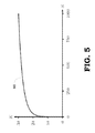
- FIG. 5 is a plot of the block length (K) for messages transmitted over a network as a function of network size (S) according to some embodiments.
- FIG. 6 is a flow diagram of a method for performing a multiple sums computation in a network according to some embodiments.
- the network resources needed to produce a predetermined linear combination of input data (which is available at a plurality of source nodes) at a plurality of destination nodes can be reduced by pre-coding the messages transmitted from the source nodes so that linear operations performed at intermediate nodes in the network automatically produce the desired linear combinations at the destination nodes.
- An additional benefit is that the interference between the messages is also canceled by choosing the pre-coding appropriately.
- a vector of input values from the source nodes is pre-coded using an invertible transfer function that relates the vectors transmitted by each source node to the vectors received by each destination node. For example, each of the source nodes can precode a vector of input values by multiplying the vector of input values with the inverse of the invertible transfer function.
- the source node can then transmit the resulting vector towards intermediate nodes in the network.
- Each intermediate node performs a linear operation to generate a linear combination of received vectors and then transmits the resulting vector to other nodes in the network.
- the invertible transfer function is determined by the linear operation performed by the intermediate nodes.
- the linear operation is chosen so that propagation of messages from the source nodes through the intermediate nodes that perform the linear operation produces the predetermined linear combination of the input values at the destination nodes.
- the linear operation may be random or deterministic.
- each of the intermediate nodes may randomly select a set of weights to perform a linear combination of the received vectors over a finite field, e.g., 2 K .
- the length K of a block of information that is transmitted by each source node is selected to be large enough that the resulting transfer function is (with high probability) invertible.
- the intermediate nodes may perform a predetermined linear combination of the received signals such as binary addition (e.g., exclusive-OR or XOR) of the received signals over the finite field, 2 .
- the predetermined linear combination is chosen such that an invertible transfer function is produced by the combined effects of the intermediate nodes. Precoding the vectors transmitted from the source nodes using the invertible transfer function results in the destination nodes receiving the predetermined linear combination of the vector of input values while also canceling interference produced by other vectors transmitted from the source nodes.
- FIG. 1 is a block diagram of a communication network 100 according to some embodiments.
- the network 100 includes a plurality of source nodes (s 1 , s 2 ) and a plurality of destination nodes (d 1 , d 2 , d 3 ).
- the source nodes (s 1 , s 2 ) and the destination nodes (d 1 , d 2 , d 3 ) communicate with each other over a network of intermediate nodes 105 .
- the terms “node” or “vertex” may be used interchangeably and refer to entities that are able to generate, transmit, receive, or process messages.
- a server may be a node or a vertex in a data mining network
- a base station may be a node or vertex in a wireless communication network
- a sensor may be a node or vertex in a sensor network.
- the source nodes (s 1 , s 2 ) and the destination nodes (d 1 , d 2 , d 3 ) are interconnected by a plurality of communication links or edges 110 (only one edge is indicated by a reference numeral in FIG. 1 in the interest of clarity).
- the terms “link” or “edge” may be used interchangeably and refer to the medium that conveys messages between nodes in the network 100 .
- the links or edges may have a direction that indicates the direction of information flow along the link or edge, e.g., the link 110 is directed from an intermediate node to the destination node d 3 .
- the communication links or edges may be wired communication links, wireless communication links, or a combination thereof.
- Each of the source nodes (s 1 , s 2 ) is able to generate a vector of input values and each of the destination nodes (d 1 , d 2 , d 3 ) is to receive a predetermined linear combination of the input values.
- the source node (s 1 ) may generate a vector of input values (a 1 , a 2 , a 3 ) and the source node (s 2 ) may generate a vector of input values (b 1 , b 2 , b 3 ).
- the destination nodes (d 1 , d 2 , d 3 ) may need to receive a predetermined linear combination of the input values such as sums of the input values over a finite field such as the finite field 2 .
- the destination node (d 1 ) may need to receive the finite field sum a 1 ⁇ b 1
- the destination node (d 2 ) may need to receive the finite field sum a 2 ⁇ b 2
- the destination node (d 2 ) may need to receive the finite field sum a 3 ⁇ b 3 .
- the intermediate nodes in the network of intermediate nodes 105 may each perform a linear operation on received vectors to generate a vector for transmission to other nodes.
- the linear operation may also be referred to as the network code for the network of intermediate nodes 105 .
- the linear operations are chosen so that propagation of the messages from source nodes (s 1 , s 2 ) through the network of intermediate nodes 105 produces the predetermined linear combinations at the destination nodes (d 1 , d 2 , d 3 ).
- the linear operations may be determined by the individual intermediate nodes in the network of intermediate nodes 105 or they may be determined by another entity such as a network controller 115 and then provided to the network of intermediate nodes 105 .
- the linear operation may be deterministic (e.g., each intermediate node may perform an addition of its received vectors over the finite field), non-deterministic, or random (e.g., each intermediate node may apply randomly selected weights to its received vectors before performing an addition of the weighted vectors over the finite field).
- Transfer functions may be defined for each of the source nodes (s 1 , s 2 ) based on the linear operations performed in the network of intermediate nodes 105 .
- each of the source nodes (s 1 , s 2 ) may transmit a pilot signal to the network of intermediate nodes 105 to the destination nodes (d 1 , d 2 , d 3 ).
- the destination nodes (d 1 , d 2 , d 3 ) may return corresponding feedback signals to the source nodes (s 1 , s 2 ) via the network of intermediate nodes 105 .
- Each of the source nodes (s 1 , s 2 ) can then compare its transmitted pilot signal to the received feedback signal to determine a transfer function that represents the effects of propagation of signals or messages through the network of intermediate nodes to each of the destination nodes (d 1 , d 2 , d 3 ).
- the transfer function for each source node (s 1 , s 2 ) may therefore relate values of the vectors transmitted from the source nodes (s 1 , s 2 ) to values of the vectors received at the destination nodes (d 1 , d 2 , d 3 ).
- Deterministic network codes may be chosen such that the transfer function is guaranteed to be invertible.
- the block size for messages transmitted by the source nodes can be selected so that the transfer function is invertible with high probability, as discussed herein.
- the network code may be modified if the transfer function is not invertible until an invertible transfer function is found.
- Messages transmitted by the source nodes (s 1 , s 2 ) can be precoded by multiplying the message by an inverse of the transfer function.
- the source nodes (s 1 , s 2 ) may then transmit the resulting precoded transmission vector towards the destination nodes (d 1 , d 2 , d 3 ) via the network of intermediate nodes 105 .
- precoding the messages using the inverse of the transfer function that is determined based on the network code implemented in the network of intermediate nodes 105 causes the network of intermediate nodes 105 to produce the predetermined linear combination of input values at the destination nodes (d 1 , d 2 , d 3 ).
- the network of intermediate nodes 105 computes the predetermined linear combination of input values at the destination nodes (d 1 , d 2 , d 3 ) as it conveys the information used to compute the linear combination. Additionally, as discussed in detail below, the network of intermediate nodes 105 cancels interference between the messages transmitted by the source nodes (s 1 , s 2 ).
- FIG. 2 is a diagram of a butterfly network 200 with two source nodes (s 1 , s 2 ) and two destination nodes (d 1 , d 2 ) according to some embodiments.
- the source nodes (s 1 , s 2 ) communicate with the two destination nodes (d 1 , d 2 ) via intermediate nodes 201 , 202 , 203 , 204 (collectively referred to herein as the intermediate nodes 201 - 204 ) and edges 210 , 211 , 212 , 213 , 214 , 215 , 216 , 217 , 218 (collectively referred to herein as the edges 210 - 218 ).
- messages transmitted by the source node (s 1 ) are denoted a d and messages transmitted by the source node (s 2 ) are denoted b d .
- the network code implemented in the butterfly network 200 is a sum or addition over the finite field 2 performed by each of the intermediate nodes 201 - 204 .
- Each intermediate node 201 - 204 sums all signals received on its incoming edges and transmits the sum over its outgoing edges.
- the network code for the butterfly network can be constructed to produce a predetermined linear combination at the destination nodes (d 1 , d 2 ).
- the destination node (d 1 ) is to receive predetermined linear combination a 1 ⁇ b 1
- the destination node (d 2 ) is to receive predetermined linear combination a 2 ⁇ b 2 .
- Each of the intermediate vertices 201 - 204 in the butterfly network 200 may therefore be configured to perform the linear operation of addition ( ⁇ ) of all incoming signals.
- the transfer matrices from the sources (s 1 , s 2 ) to the destination nodes (d 1 , d 2 ) can be defined as H s ⁇ 2 2 ⁇ 2 .
- the transfer matrices for the butterfly network 200 can be defined as:
- the signals in the butterfly network 200 are therefore aligned to perform the desired computation and cancel interference.
- the first source s 1 sends a 1 ⁇ a 2 over its first outgoing edge 212 and a 2 over its second outgoing edge 210 .
- the second source s 2 sends b 2 over its first outgoing edge 211 and b 1 ⁇ b 2 over its second outgoing edge 214 .
- the intermediate vertex 203 with edge 212 to the first destination d 1 receives two signals a 1 ⁇ a 2 and a 2 ⁇ b 1 over its incoming edges 212 , 215 .
- the second signal from the first source a 2 is not required at the first destination d 1 and hence can be considered interference.
- the interference a 2 is present in both signals a 1 ⁇ a 2 and a 2 ⁇ b 1 and is consequently removed by the vertex 203 when the vertex 203 performs the linear operation of addition over the finite field 2 .
- Performing the linear operation of addition over the finite field 2 at the vertex 203 also generates the desired sum a 1 ⁇ b 1 of the signals provided by the two sources, which can then be provided to the first destination d 1 .
- the desired signal and the interference are therefore aligned.
- the sum that is desired at the second destination d 2 is also calculated by the network 200 .
- the interference b 1 is present in both signals a 2 ⁇ b 1 and b 1 ⁇ b 2 and is consequently removed by the vertex 204 when the vertex performs the linear operation of addition over the finite field 2 .
- Performing the linear operation of addition over the finite field 2 at the vertex 204 also generates the desired sum a 2 ⁇ b 2 of the signals provided by the two sources, which can then be provided to the first destination d 1 .
- This example illustrates that the proposed solution to the problem of distributed computation of multiple sums over a network satisfies an end-to-end principle.
- the network itself is “dumb” and only performs simple linear combinations of all incoming signals at each vertex.
- the “smart” operations happen at the edge of the network, where the sources have to invert the transfer matrix to the destinations and precode transmitted messages using the inverted transfer matrix.
- FIG. 3 is a diagram of a double butterfly network 300 that includes two source nodes (s 1 , s 2 ) and three destination nodes (d 1 , d 2 , d 3 ) according to some embodiments.
- the source nodes (s 1 , s 2 ) communicate with the destination nodes (d 1 , d 2 , d 3 ) via intermediate nodes 301 , 302 , 303 , 304 , 305 , 306 , 307 , (collectively referred to herein as the intermediate nodes 301 - 307 ) and edges 310 , 311 , 312 , 313 , 314 , 315 , 316 , 317 , 318 , 319 , 320 , 321 , 322 , 323 , 324 (collectively referred to herein as the edges 310 - 324 ).
- messages transmitted by the first source are denoted a d and messages transmitted by the second source are denoted b d .
- Each intermediate vertex 301 - 307 in the double butterfly network 300 sums all signals received on the incoming edges 310 - 324 and transmits the sum over all outgoing edges 310 - 324 .
- the network code for the double butterfly network 300 can be constructed to produce a predetermined linear combination at the destination nodes (d 1 , d 2 , d 3 ).
- the destination node (d 1 ) is to receive predetermined linear combination a 1 ⁇ b 1
- the destination node (d 2 ) is to receive predetermined linear combination a 2 ⁇ b 2
- the destination node (d 3 ) is to receive predetermined linear combination a 3 ⁇ b 3
- Each of the intermediate vertices 301 - 307 in the double butterfly network 300 may therefore be configured to perform the linear operation of addition ( ⁇ ) of all incoming signals.
- the transfer matrices from the source s to the destinations can then be defined as H s ⁇ 2 3 ⁇ 3 .
- the transfer matrices for the double butterfly network 300 can be defined as:
- the network code embodied in the double butterfly network 300 exhibits alignment.
- the first source s 1 sends the message a 1 ⁇ a 2 ⁇ a 3 over its first outgoing edge 310 , a 1 ⁇ a 2 over its second outgoing edge 311 , and a 2 over its third outgoing edge 312 .
- the second source s 2 sends b 2 over its first outgoing edge 313 , b 1 ⁇ b 2 over its second outgoing edge 314 , and b 1 ⁇ b 2 ⁇ b 3 over its third outgoing edge 315 .
- the intermediate vertex 305 with an edge 322 to the first destination d 1 receives a 1 ⁇ a 2 ⁇ a 3 and b 1 ⁇ a 2 ⁇ a 3 over its two incoming edges 310 , 318 .
- the portion a 2 ⁇ a 3 is interference. Since this term is present in both the received signals, the interference is aligned and can be removed through the addition operation performed at the vertex 305 according to the network code.
- the desired signals a 1 and b 1 at the vertex 305 are also aligned and adding the signals according to the network code performs the desired linear operation a 1 ⁇ b 1 .
- Alignment of the interference and the desired signals is also visible at the other two intermediate vertices 306 , 307 connected to the destinations d 2 and d 3 .
- the linear combination b 1 ⁇ a 3 is interference while a 2 and b 2 are desired signals.
- the same signal b 1 ⁇ a 2 ⁇ a 3 is received from the vertex 303 by the vertex 305 connected to d 1 over the edge 318 and the vertex 306 connected to d 2 over the edge 319 .
- different parts of the signal are interference and desired signal.
- the signal b 1 ⁇ a 2 ⁇ a 3 should be aligned with respect to both of these vertices 305 , 306 .
- the signal received by the vertices 305 , 306 is thus over constrained. However, both alignment constraints can be satisfied simultaneously. Feasibility of the simultaneous alignment is due to the judicious choice of the signal injected by the sources, as discussed below.
- FIG. 2 and FIG. 3 illustrate the process of configuring and operating the butterfly network 200 and the double butterfly network 300 , respectively, other embodiments can generalize the technique to arbitrary linear functions over the finite field q and edge signals over the finite field q K .
- the extension of the computation to arbitrary linear operations or linear functions follows by pre-multiplying every message from the source s by the appropriate coefficient as determined by the linear combinations of the input data requested or expected by destination d.
- a subset S ⁇ V of the vertices are source nodes and a disjoint subset D ⁇ V are destination nodes.
- the notation may be simplified by setting: S
- the number of source nodes S and the number of destination nodes D may not necessarily be the same in all embodiments.
- Each source node s ⁇ S has access to K messages w sd [1], w sd [2], . . .
- Each destination node d in the illustrated embodiment aims to compute a linear combination represented by the K sums:
- Each edge in the network is able to carry a signal in 2 K between the two vertices that are connected by the edge.
- the signal is carried in the direction of the orientation of the edge.
- a network code describes the linear operations performed at the vertices in the network by specifying how each vertex maps the signals received over its incoming edges to signals that are sent over its outgoing edges. For a fixed value of the block size K, the network code solves the multiple sums computation problem over the network G if the destination vertices D are able to compute predetermined linear combinations (e.g., the multiple sums) for every possible value of the KDS binary messages.
- the multiple sums computation problem over the network G is feasible if there exists a value of the block size K and a network code of length K that solves this problem over the network G.
- Some embodiments discussed herein illustrate the computation and communication of signals over the binary field 2 . However, embodiments of these techniques may be extended to general fields q . Some embodiments may also be used to compute arbitrary linear combinations (with potentially different coefficients at each destination node) instead of computing simple sums or additions.
- the multiple sums computation is performed over the network G with S sources S and D destinations D assuming that for every source s ⁇ S and every subset of destination nodes ⁇ tilde over (D) ⁇ D the (vertex) min cut between s and D is at least
- This may be referred to as a cut condition.
- the graph G may represent the network 100 shown in FIG. 1 , which satisfies a cut condition so that a network code exists to perform the multiple sums computation problem described herein.
- the general graph G can then be converted or transformed into a standardized form and a network code can be constructed for the standardized form of the graph.
- FIG. 4 is a diagram that illustrates conversion of a multiple sums computation problem over the communication network 100 shown in FIG. 1 into a standard form 400 according to some embodiments.
- each source node s ⁇ S has exactly D outgoing edges and that each destination node d ⁇ D has exactly one incoming edge.
- some embodiments may have different numbers of outgoing edges from some or all of the source nodes or different numbers of in going edges to each destination node.
- the cut condition implies that each source node has at least D outgoing edges. Consider a source s with strictly more than D outgoing edges. Add D+1 additional vertices (as depicted in FIG.
- the cut condition implies that each destination node d has at least one incoming edge.
- a destination node d with more than one incoming edge can be converted into a destination node with a single incoming edge.
- one additional vertex d′ (as depicted in FIG. 4 by the solid circles connected to the destinations d 1 and d 3 ) may be added to the graph and declare the new vertex to be the new destination node, as shown in FIG. 4 .
- the modified graph also satisfies the cut condition.
- a network which may be referred to as a “normalized” network, includes sources such that every source has exactly D outgoing edges and every destination node has exactly one incoming edge.
- the block length K may be fixed to a particular value so that the network edges carry symbols over the finite field 2 K .
- the intermediate vertices perform random linear network coding over the finite field. For example, assume a vertex v ⁇ tilde over (V) ⁇ as in-degree i and out-degree o. Let y v ⁇ 2 K i and x v ⁇ 2 K o be the input and output vectors of that vertex.
- the coefficients of the matrices A v for all intermediate vertices v ⁇ V ⁇ S ⁇ D ⁇ are chosen independently and uniformly at random from the finite field 2 K.
- the end-to-end mapping of the signals sent by the source nodes to the signals received by the destination nodes can be considered.
- source node s ⁇ S transmits the signal x s ⁇ 2 K D , noting that, by the normalization assumption, all source vectors have the same number of elements D.
- y d ⁇ 2 K be the signal received by the destination nodes d ⁇ D, noting that by the normalization assumption each destination node observes a scalar signal.
- FIG. 5 is a plot 500 of the block length (K) for messages transmitted over a network having a size (S) according to some embodiments.
- the block length satisfying equation (2) is shown on the vertical axis and the system size in arbitrary units is shown on the horizontal axis.
- the plot 500 shows that the scaling of block length with the network size is quite benign and this is assumed to be the case in the following discussion.
- each source s knows its transfer matrix, e.g. based on feedback received in response to pilot signals transmitted by each source s, as discussed herein.
- Sums can be computed over the network-coded system using linear operations performed by the intermediate nodes. Since the linear operations of the intermediate nodes are fixed, only the operations of the source nodes in the destination nodes are left to describe or specify.
- the symbols y d and w sd and the sum operation in equation (3) are performed in the extension field 2 K .
- the aim of each destination node is to recover the sums ⁇ s ⁇ S w sd [k] over the base field 2 .
- the mapping from the message bits w sd [k] ⁇ 2 to the finite field symbol w sd ⁇ 2 K needs to be done with some care.
- the extension field 2 K can be constructed as 2 [ ⁇ ]/ ⁇ ( ⁇ ), i.e., the congruence classes of polynomials (in the indeterminate ⁇ ) over 2 modulo the irreducible polynomial ⁇ ( ⁇ ) of degree K.
- equation (3) can be rewritten as:
- y d ⁇ ⁇ s ⁇ S ⁇ w sd ⁇ ⁇ ( ⁇ s ⁇ S ⁇ w sd ⁇ [ 1 ] ) + ( ⁇ s ⁇ S ⁇ w sd ⁇ [ 2 ] ) ⁇ ⁇ + ( ⁇ s ⁇ S ⁇ w sd ⁇ [ 3 ] ) ⁇ ⁇ 2 + ... + ⁇ ( ⁇ s ⁇ S ⁇ w sd ⁇ [ K ] ) ⁇ ⁇ K - 1 ⁇ ( mod ⁇ ⁇ p ⁇ ( ⁇ ) .
- each destination node can recover the desired sums of the message bits over 2 from the K coefficients of y d .
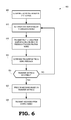
- FIG. 6 is a flow diagram of a method 600 for performing a multiple sums computation in a network according to some embodiments.
- the method 600 may be implemented in a network controller, one or more source nodes, one or more intermediate nodes, one or more destination nodes, or combinations thereof. Examples of these entities are shown in FIGS. 1-3 .
- a block size for messages transmitted to the network is determined based on a system size, which may be estimated based on a number of source nodes, a number of intermediate nodes, a number of destination nodes, a number of edges, and the like.
- the block size may be determined using equation (2) or a representation of the block size as a function of system size such as the plot 500 shown in FIG. 5 .
- the linear operation performed by the intermediate nodes may be set.
- the linear operation may be set deterministically, non-deterministically, or randomly, as discussed herein.
- the linear operation may be determined by an external entity such as a network controller or may be determined by the individual intermediate nodes.
- source nodes transmit (or re-transmit during subsequent iterations if a non-invertible transfer matrix was found) pilot signals through the network and then receive feedback signals from the destination nodes.
- the source nodes determine their transfer matrices by comparing the translated pilot signals to the feedback signals received from the destination nodes in response to the pilot signals.
- the source nodes may determine whether the transfer matrices are invertible. If not, the method 600 flows back to block 610 and the linear operation performed by the intermediate nodes is modified or reset, e.g., by selecting a new set of random weights, and the pilot signal is re-transmitted at block 615 . Once the source nodes determine that the transfer matrices are invertible, the source node can precode (at block 630 ) messages based on the invertible transfer matrices and then transmit the messages over the network at block 635 .
- certain aspects of the techniques described above may be implemented by one or more processors of a processing system executing software.
- the software comprises one or more sets of executable instructions stored or otherwise tangibly embodied on a non-transitory computer readable storage medium.
- the software can include the instructions and certain data that, when executed by the one or more processors, manipulate the one or more processors to perform one or more aspects of the techniques described above.
- the non-transitory computer readable storage medium can include, but is not limited to, optical media (e.g., compact disc (CD), digital versatile disc (DVD), Blu-Ray disc), magnetic media (e.g., floppy disc, magnetic tape, or magnetic hard drive), volatile memory (e.g., random access memory (RAM) or cache), non-volatile memory (e.g., read-only memory (ROM) or Flash memory), or microelectromechanical systems (MEMS)-based storage media.
- optical media e.g., compact disc (CD), digital versatile disc (DVD), Blu-Ray disc
- magnetic media e.g., floppy disc, magnetic tape, or magnetic hard drive
- volatile memory e.g., random access memory (RAM) or cache
- non-volatile memory e.g., read-only memory (ROM) or Flash memory
- MEMS microelectromechanical systems
- the computer readable storage medium may be embedded in the computing system (e.g., system RAM or ROM), fixedly attached to the computing system (e.g., a magnetic hard drive), removably attached to the computing system (e.g., an optical disc or Universal Serial Bus (USB)-based Flash memory), or coupled to the computer system via a wired or wireless network (e.g., network accessible storage (NAS)).
- the executable instructions stored on the non-transitory computer readable storage medium may be in source code, assembly language code, object code, or other instruction format that is interpreted or otherwise executable by one or more processors.
Abstract
Description
H 1 x 1 ⊕H 2 x 2
over their incoming edges. Adopting the convention that the edges coming out of the sources are labeled from left to right, the transfer matrices for the
If the source s1 transmits:
and the source s2 transmits:
then the destination nodes (d1, d2) receive the desired sums:
If the source s1 transmits:
and the source s2 transmits:
then the destinations received the desired sums:
S
D
The number of source nodes S and the number of destination nodes D may not necessarily be the same in all embodiments. Each source node sεS has access to K messages wsd[1], wsd[2], . . . , wsd[K] for each destination node dεD. Each of these messages has a value defined over the binary field
with kε{1, 2, . . . , K} and where the sum is over the binary field
x v =A v y v,
where Avε
y
of received signal at the destination nodes. Since all operations of the network are linear, the mapping between (xs)sεS and y is also linear. Thus, the input-output relationship is:
y=Σ sεS H s x s (1)
with transfer matrix Hsε
where E represents the edge set of the network. Using the union bound, one can show:
As K→∞, the right-hand side of the above expression approaches zero. More precisely, for block length:
with probability at least 1−δ that all transfer matrices Hs are invertible.
w s
Each source s uses a linear precoder to map the message vector ws to the vector:
x s =H s −1 w s
of signals injected into the network. This operation is possible because Hs is invertible by construction.
where the sum is over the finite field
y d=ΣsεS w sd. (3)
The symbols yd and wsd and the sum operation in equation (3) are performed in the extension field
w sd ≡w sd[1]+w sd[2]α+w sd[3]α2 + . . . +w sd [K]α K-1(mod ρ(α)).
Using this expression, equation (3) can be rewritten as:
In the above expression, the first (upper) sum is over the extension field
Claims (20)
Priority Applications (1)
| Application Number | Priority Date | Filing Date | Title |
|---|---|---|---|
| US14/152,518 US9524271B2 (en) | 2014-01-10 | 2014-01-10 | Distributed computation of linear combinations in a network |
Applications Claiming Priority (1)
| Application Number | Priority Date | Filing Date | Title |
|---|---|---|---|
| US14/152,518 US9524271B2 (en) | 2014-01-10 | 2014-01-10 | Distributed computation of linear combinations in a network |
Publications (2)
| Publication Number | Publication Date |
|---|---|
| US20150201000A1 US20150201000A1 (en) | 2015-07-16 |
| US9524271B2 true US9524271B2 (en) | 2016-12-20 |
Family
ID=53522379
Family Applications (1)
| Application Number | Title | Priority Date | Filing Date |
|---|---|---|---|
| US14/152,518 Active 2035-01-25 US9524271B2 (en) | 2014-01-10 | 2014-01-10 | Distributed computation of linear combinations in a network |
Country Status (1)
| Country | Link |
|---|---|
| US (1) | US9524271B2 (en) |
Families Citing this family (2)
| Publication number | Priority date | Publication date | Assignee | Title |
|---|---|---|---|---|
| US9817751B2 (en) * | 2014-09-03 | 2017-11-14 | Apple Inc. | Multi-phase programming schemes for nonvolatile memories |
| CN110059731B (en) * | 2019-03-27 | 2022-08-23 | 南京邮电大学 | Node importance evaluation method based on weighted K-order propagation number |
Citations (5)
| Publication number | Priority date | Publication date | Assignee | Title |
|---|---|---|---|---|
| US20020122470A1 (en) * | 2000-12-29 | 2002-09-05 | Heikkila Markku J. | Method and apparatus for providing blind adaptive estimation and reception |
| US20110103402A1 (en) * | 2009-11-05 | 2011-05-05 | Canon Kabushiki Kaisha | Method and Device for Decoding, Corresponding Computer Program Product, Storage Means and Destination Node |
| US20110116581A1 (en) * | 2008-07-28 | 2011-05-19 | Ryota Yamada | Communication system, reception device, and communication method |
| US20120218891A1 (en) * | 2009-08-28 | 2012-08-30 | Jay Kumar Sundararajan | Method and apparatus providing network coding based flow control |
| US20140222748A1 (en) * | 2013-02-05 | 2014-08-07 | Cisco Technology, Inc. | Traffic-based inference of influence domains in a network by using learning machines |
-
2014
- 2014-01-10 US US14/152,518 patent/US9524271B2/en active Active
Patent Citations (5)
| Publication number | Priority date | Publication date | Assignee | Title |
|---|---|---|---|---|
| US20020122470A1 (en) * | 2000-12-29 | 2002-09-05 | Heikkila Markku J. | Method and apparatus for providing blind adaptive estimation and reception |
| US20110116581A1 (en) * | 2008-07-28 | 2011-05-19 | Ryota Yamada | Communication system, reception device, and communication method |
| US20120218891A1 (en) * | 2009-08-28 | 2012-08-30 | Jay Kumar Sundararajan | Method and apparatus providing network coding based flow control |
| US20110103402A1 (en) * | 2009-11-05 | 2011-05-05 | Canon Kabushiki Kaisha | Method and Device for Decoding, Corresponding Computer Program Product, Storage Means and Destination Node |
| US20140222748A1 (en) * | 2013-02-05 | 2014-08-07 | Cisco Technology, Inc. | Traffic-based inference of influence domains in a network by using learning machines |
Non-Patent Citations (2)
| Title |
|---|
| Ralf Koetter, Muriel Medard An algebraic approach to network codin, IEEE/ACM Transactions on Networking (TON) archive, vol. 11 Issue 5, Oct. 2003, pp. 782-795. * |
| Tracy Ho et al., "A Random Linear Network Coding Approach to Multicast", IEEE Transactions on Information Theory, Oct. 2006, 18 pages. |
Also Published As
| Publication number | Publication date |
|---|---|
| US20150201000A1 (en) | 2015-07-16 |
Similar Documents
| Publication | Publication Date | Title |
|---|---|---|
| Khan et al. | Federated learning for internet of things: Recent advances, taxonomy, and open challenges | |
| Sharma et al. | Fundamental bound on the reliability of quantum information transmission | |
| Tamo et al. | Access versus bandwidth in codes for storage | |
| CN107979409B (en) | Inter-orbit satellite communication routing method and device | |
| Shanmugam et al. | Bounding multiple unicasts through index coding and locally repairable codes | |
| WO2017020680A1 (en) | Uplink data sending method, receiving method and device | |
| Li et al. | Communication-aware computing for edge processing | |
| JP5004869B2 (en) | Network route selection method and communication system | |
| US9524271B2 (en) | Distributed computation of linear combinations in a network | |
| KR101199292B1 (en) | Method for Controlling Multi-Sink/Multi-Path Routing Sensor Network and Sensor Network System using the same | |
| US11362810B2 (en) | Method and system for rateless and pollution-attack-resilient network coding | |
| EP2487799B1 (en) | Apparatus and method for bidirectional communication between multi-nodes using relay node | |
| Badia-Sampera et al. | Towards more realistic network models based on graph neural networks | |
| US20240048157A1 (en) | Encoding method, decoding method, electronic device and storage medium | |
| Li et al. | Sparse random linear network coding with precoded band codes | |
| de Beaudrap et al. | Quantum linear network coding for entanglement distribution in restricted architectures | |
| KR20190117186A (en) | Learning-based channel code decoding method and apparatus | |
| US11728977B2 (en) | Method for efficient and practical key distribution in network coding systems | |
| EP3086515A1 (en) | Transmission method and transmission device for data packet | |
| US20170317986A1 (en) | Method and system for rateless and pollution-attack-resilient network coding including decoder(s) | |
| JP5936073B2 (en) | Multicast quantum network coding method | |
| JP6597231B2 (en) | Arithmetic device, program, information processing method | |
| Lvov et al. | Initialization algorithms for convolutional network coding | |
| JP5388716B2 (en) | Distributed information generating apparatus, secret information restoring apparatus, shared information generating method, secret information restoring method, and program | |
| Nóbrega et al. | On multiplicative matrix channels over finite chain rings |
Legal Events
| Date | Code | Title | Description |
|---|---|---|---|
| AS | Assignment |
Owner name: ALCATEL-LUCENT USA INC., NEW JERSEY Free format text: ASSIGNMENT OF ASSIGNORS INTEREST;ASSIGNORS:NIESEN, URS;GUPTA, PIYUSH;REEL/FRAME:032360/0498 Effective date: 20140129 |
|
| AS | Assignment |
Owner name: CREDIT SUISSE AG, NEW YORK Free format text: SECURITY INTEREST;ASSIGNOR:ALCATEL LUCENT USA, INC.;REEL/FRAME:032845/0558 Effective date: 20140506 |
|
| AS | Assignment |
Owner name: ALCATEL-LUCENT USA INC., NEW JERSEY Free format text: RELEASE OF SECURITY INTEREST;ASSIGNOR:CREDIT SUISSE AG;REEL/FRAME:033654/0693 Effective date: 20140819 |
|
| AS | Assignment |
Owner name: ALCATEL LUCENT, FRANCE Free format text: ASSIGNMENT OF ASSIGNORS INTEREST;ASSIGNOR:ALCATEL-LUCENT USA INC.;REEL/FRAME:035053/0670 Effective date: 20150224 |
|
| STCF | Information on status: patent grant |
Free format text: PATENTED CASE |
|
| FEPP | Fee payment procedure |
Free format text: PAYER NUMBER DE-ASSIGNED (ORIGINAL EVENT CODE: RMPN); ENTITY STATUS OF PATENT OWNER: LARGE ENTITY Free format text: PAYOR NUMBER ASSIGNED (ORIGINAL EVENT CODE: ASPN); ENTITY STATUS OF PATENT OWNER: LARGE ENTITY |
|
| MAFP | Maintenance fee payment |
Free format text: PAYMENT OF MAINTENANCE FEE, 4TH YEAR, LARGE ENTITY (ORIGINAL EVENT CODE: M1551); ENTITY STATUS OF PATENT OWNER: LARGE ENTITY Year of fee payment: 4 |