US9520790B2 - Interleaved LLC converters and current sharing method thereof - Google Patents
Interleaved LLC converters and current sharing method thereof Download PDFInfo
- Publication number
- US9520790B2 US9520790B2 US14/206,743 US201414206743A US9520790B2 US 9520790 B2 US9520790 B2 US 9520790B2 US 201414206743 A US201414206743 A US 201414206743A US 9520790 B2 US9520790 B2 US 9520790B2
- Authority
- US
- United States
- Prior art keywords
- llc power
- llc
- power converters
- output voltage
- power converter
- Prior art date
- Legal status (The legal status is an assumption and is not a legal conclusion. Google has not performed a legal analysis and makes no representation as to the accuracy of the status listed.)
- Active, expires
Links
- 238000000034 method Methods 0.000 title claims abstract description 32
- 230000001965 increasing effect Effects 0.000 claims abstract description 16
- 239000003990 capacitor Substances 0.000 claims description 12
- 238000004804 winding Methods 0.000 claims description 7
- 230000008878 coupling Effects 0.000 claims description 6
- 238000010168 coupling process Methods 0.000 claims description 6
- 238000005859 coupling reaction Methods 0.000 claims description 6
- 238000010586 diagram Methods 0.000 description 2
- 230000000694 effects Effects 0.000 description 1
- 230000005669 field effect Effects 0.000 description 1
- 230000001939 inductive effect Effects 0.000 description 1
- 229910044991 metal oxide Inorganic materials 0.000 description 1
- 150000004706 metal oxides Chemical class 0.000 description 1
- 239000004065 semiconductor Substances 0.000 description 1
Images


Classifications
-
- H—ELECTRICITY
- H02—GENERATION; CONVERSION OR DISTRIBUTION OF ELECTRIC POWER
- H02M—APPARATUS FOR CONVERSION BETWEEN AC AND AC, BETWEEN AC AND DC, OR BETWEEN DC AND DC, AND FOR USE WITH MAINS OR SIMILAR POWER SUPPLY SYSTEMS; CONVERSION OF DC OR AC INPUT POWER INTO SURGE OUTPUT POWER; CONTROL OR REGULATION THEREOF
- H02M3/00—Conversion of dc power input into dc power output
- H02M3/22—Conversion of dc power input into dc power output with intermediate conversion into ac
- H02M3/24—Conversion of dc power input into dc power output with intermediate conversion into ac by static converters
- H02M3/28—Conversion of dc power input into dc power output with intermediate conversion into ac by static converters using discharge tubes with control electrode or semiconductor devices with control electrode to produce the intermediate ac
- H02M3/285—Single converters with a plurality of output stages connected in parallel
-
- H—ELECTRICITY
- H02—GENERATION; CONVERSION OR DISTRIBUTION OF ELECTRIC POWER
- H02M—APPARATUS FOR CONVERSION BETWEEN AC AND AC, BETWEEN AC AND DC, OR BETWEEN DC AND DC, AND FOR USE WITH MAINS OR SIMILAR POWER SUPPLY SYSTEMS; CONVERSION OF DC OR AC INPUT POWER INTO SURGE OUTPUT POWER; CONTROL OR REGULATION THEREOF
- H02M1/00—Details of apparatus for conversion
- H02M1/0048—Circuits or arrangements for reducing losses
- H02M1/0054—Transistor switching losses
- H02M1/0058—Transistor switching losses by employing soft switching techniques, i.e. commutation of transistors when applied voltage is zero or when current flow is zero
-
- H02M2001/0058—
-
- H02M2003/1586—
-
- H—ELECTRICITY
- H02—GENERATION; CONVERSION OR DISTRIBUTION OF ELECTRIC POWER
- H02M—APPARATUS FOR CONVERSION BETWEEN AC AND AC, BETWEEN AC AND DC, OR BETWEEN DC AND DC, AND FOR USE WITH MAINS OR SIMILAR POWER SUPPLY SYSTEMS; CONVERSION OF DC OR AC INPUT POWER INTO SURGE OUTPUT POWER; CONTROL OR REGULATION THEREOF
- H02M3/00—Conversion of dc power input into dc power output
- H02M3/02—Conversion of dc power input into dc power output without intermediate conversion into ac
- H02M3/04—Conversion of dc power input into dc power output without intermediate conversion into ac by static converters
- H02M3/10—Conversion of dc power input into dc power output without intermediate conversion into ac by static converters using discharge tubes with control electrode or semiconductor devices with control electrode
- H02M3/145—Conversion of dc power input into dc power output without intermediate conversion into ac by static converters using discharge tubes with control electrode or semiconductor devices with control electrode using devices of a triode or transistor type requiring continuous application of a control signal
- H02M3/155—Conversion of dc power input into dc power output without intermediate conversion into ac by static converters using discharge tubes with control electrode or semiconductor devices with control electrode using devices of a triode or transistor type requiring continuous application of a control signal using semiconductor devices only
- H02M3/156—Conversion of dc power input into dc power output without intermediate conversion into ac by static converters using discharge tubes with control electrode or semiconductor devices with control electrode using devices of a triode or transistor type requiring continuous application of a control signal using semiconductor devices only with automatic control of output voltage or current, e.g. switching regulators
- H02M3/158—Conversion of dc power input into dc power output without intermediate conversion into ac by static converters using discharge tubes with control electrode or semiconductor devices with control electrode using devices of a triode or transistor type requiring continuous application of a control signal using semiconductor devices only with automatic control of output voltage or current, e.g. switching regulators including plural semiconductor devices as final control devices for a single load
- H02M3/1584—Conversion of dc power input into dc power output without intermediate conversion into ac by static converters using discharge tubes with control electrode or semiconductor devices with control electrode using devices of a triode or transistor type requiring continuous application of a control signal using semiconductor devices only with automatic control of output voltage or current, e.g. switching regulators including plural semiconductor devices as final control devices for a single load with a plurality of power processing stages connected in parallel
- H02M3/1586—Conversion of dc power input into dc power output without intermediate conversion into ac by static converters using discharge tubes with control electrode or semiconductor devices with control electrode using devices of a triode or transistor type requiring continuous application of a control signal using semiconductor devices only with automatic control of output voltage or current, e.g. switching regulators including plural semiconductor devices as final control devices for a single load with a plurality of power processing stages connected in parallel switched with a phase shift, i.e. interleaved
-
- H—ELECTRICITY
- H02—GENERATION; CONVERSION OR DISTRIBUTION OF ELECTRIC POWER
- H02M—APPARATUS FOR CONVERSION BETWEEN AC AND AC, BETWEEN AC AND DC, OR BETWEEN DC AND DC, AND FOR USE WITH MAINS OR SIMILAR POWER SUPPLY SYSTEMS; CONVERSION OF DC OR AC INPUT POWER INTO SURGE OUTPUT POWER; CONTROL OR REGULATION THEREOF
- H02M3/00—Conversion of dc power input into dc power output
- H02M3/22—Conversion of dc power input into dc power output with intermediate conversion into ac
- H02M3/24—Conversion of dc power input into dc power output with intermediate conversion into ac by static converters
- H02M3/28—Conversion of dc power input into dc power output with intermediate conversion into ac by static converters using discharge tubes with control electrode or semiconductor devices with control electrode to produce the intermediate ac
- H02M3/325—Conversion of dc power input into dc power output with intermediate conversion into ac by static converters using discharge tubes with control electrode or semiconductor devices with control electrode to produce the intermediate ac using devices of a triode or a transistor type requiring continuous application of a control signal
- H02M3/335—Conversion of dc power input into dc power output with intermediate conversion into ac by static converters using discharge tubes with control electrode or semiconductor devices with control electrode to produce the intermediate ac using devices of a triode or a transistor type requiring continuous application of a control signal using semiconductor devices only
-
- Y—GENERAL TAGGING OF NEW TECHNOLOGICAL DEVELOPMENTS; GENERAL TAGGING OF CROSS-SECTIONAL TECHNOLOGIES SPANNING OVER SEVERAL SECTIONS OF THE IPC; TECHNICAL SUBJECTS COVERED BY FORMER USPC CROSS-REFERENCE ART COLLECTIONS [XRACs] AND DIGESTS
- Y02—TECHNOLOGIES OR APPLICATIONS FOR MITIGATION OR ADAPTATION AGAINST CLIMATE CHANGE
- Y02B—CLIMATE CHANGE MITIGATION TECHNOLOGIES RELATED TO BUILDINGS, e.g. HOUSING, HOUSE APPLIANCES OR RELATED END-USER APPLICATIONS
- Y02B70/00—Technologies for an efficient end-user side electric power management and consumption
- Y02B70/10—Technologies improving the efficiency by using switched-mode power supplies [SMPS], i.e. efficient power electronics conversion e.g. power factor correction or reduction of losses in power supplies or efficient standby modes
-
- Y02B70/1425—
-
- Y02B70/1491—
Definitions
- the field of the invention relates generally to power converters, and more specifically, to interleaved inductor-inductor-capacitor (LLC) converters.
- LLC interleaved inductor-inductor-capacitor
- a method for current sharing between a first LLC power converter interleaved with a second LLC power converter.
- the method includes determining an expected output voltage for at least one of the first and second LLC power converters and measuring an output voltage of at least one of the first and second LLC power converters.
- the method also includes increasing a dead-time of at least one of the first and second LLC power converters when the measured output voltage exceeds the expected output voltage.
- the method includes interleaving the first and second LLC power converters, wherein an output current of the first LLC power converter is substantially equal to an output current of the second LLC power converter.
- a system in another embodiment, includes a first LLC power converter, and a second LLC power converter interleaved with the first LLC power converter.
- a dead-time of at least one of the first and the second LLC power converters is configured such that an output current of the first LLC power converter is substantially equal to an output current of the second LLC power converter.
- a method is provided of interleaving a first LLC power converter and a second LLC power converter.
- the method includes calibrating a dead-time for at least one of the first and second LLC power converters such that an output current of the first LLC power converter is substantially equal to an output current of the second LLC power converter.
- the method also includes coupling the first and second LLC power converters to a common load and coupling the first LLC power converter to a first power source and the second LLC power converter to a second power source.
- FIG. 1 is a block diagram of an exemplary system for an interleaving of a first LLC power converter and a second LLC power converter.
- FIG. 2 is a graph of output currents of the exemplary interleaved LLC power converters shown in FIG. 1 without dead-time control.
- FIG. 3 is a graph of output currents of the exemplary interleaved LLC power converters shown in FIG. 1 with dead-time control.
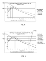
- FIG. 4 is a graph of gain curves for the first and second LLC power converters shown in FIG. 1 for a fixed input and a fixed load.
- FIG. 5 is a graph of gain curves for the first and second LLC power converters shown in FIG. 1 with dead-time control.
- FIG. 1 is a block diagram of one embodiment of a system 200 for interleaving a first LLC power converter 201 and a second LLC power converter 241 .
- first LLC power converter 201 includes a first power source 205 that acts as an LLC power converter voltage source. More specifically, in an exemplary embodiment, first power source 205 is an equivalent Thevenin voltage source that generates a square wave voltage output. The square wave voltage output of first power source 205 may be measured across a junction of two Metal Oxide Semiconductor Field Effect Transistors (“MOSFETs”) (not shown) of a bridge circuit.
- MOSFETs Metal Oxide Semiconductor Field Effect Transistors
- First LLC power converter 201 also includes a first resonant inductor 210 coupled to first voltage source 205 , and a first resonant capacitor 215 coupled to first resonant inductor 210 .
- First LLC power converter 201 also includes a first transformer 220 having a first magnetic inductor 224 coupled to first resonant capacitor 215 and is a primary winding of first transformer 220 .
- First magnetic inductor 224 is also coupled to first power source 205 .
- First transformer 220 also includes a secondary winding 228 .
- second LLC power converter 241 includes a second power source 270 . More specifically, in an exemplary embodiment, second power source 270 is an equivalent Thevenin voltage source that generates a square wave voltage output. The square wave voltage output of second power source 270 may be measured across a junction of two MOSFETs of a bridge circuit. Second LLC power converter 241 includes a second resonant inductor 260 coupled to second power source 270 , and a second resonant capacitor 250 coupled to second resonant inductor 260 . Second LLC power converter 241 also includes a second transformer 240 having a second magnetic inductor 244 coupled to second resonant capacitor 250 and is a primary winding of second transformer 240 .
- secondary winding 228 of first transformer 220 is coupled in parallel to a common load 230 .
- Secondary winding 248 of second transformer 240 is also coupled in parallel to common load 230 .
- Common load 230 is magnetically couplable to first and second LLC power converters 201 and 241 .
- first LLC power converter 201 and second LLC power converter 241 should output substantially the same amount of current so that common load 230 is driven by both LLC power converters 201 and 241 .
- High inductive variation creates difficulties in interleaving LLC power converters.
- system 200 interleaves LLC power converters 201 and 241 to operate at a substantially equal output current.
- dead-time may be defined as a wait time between powering transformers 220 and 240 in a first direction and powering transformers 220 and 240 in a second direction to prevent a short of one of power sources 205 and 270 .
- dead-time may also be defined as a time when there are no active signals between the MOSFETs of the bridge circuit. The dead-time is obtained during calibration by comparing an open-loop response of each of LLC power converters 201 and 241 at nominal resonant frequency. The dead-time is increased for whichever of the first and second LLC power converters measures a higher output voltage when tested in open-loop.
- configuring LLC power converters 201 and 241 to current share includes determining an expected output voltage for at least one of LLC power converters 201 and 241 . Determining an expected output voltage may include predicting an output voltage using a predetermined input voltage, a predetermined frequency, and/or a known load applied to each LLC power converter 201 and 241 . An output voltage of one of LLC power converter 201 and LLC power converter 241 is then is measured. In some embodiments, measuring an output voltage includes measuring respective output voltages of each of first and second LLC power converters 201 and 241 . The measured respective output voltages are compared to the expected values. When the measured output voltage exceeds the expected output voltage, the dead-time of the converter is increased. This process is repeated until the measured output voltage is substantially equal to the expected output voltage.
- the output voltages of each of first and second LLC power converters 201 and 241 are measured and compared to each other.
- the dead-time is increased for whichever of first and second LLC power converters 201 and 241 measures a higher output voltage. Increasing the dead-time of a particular LLC power converter effectively lowers a gain for that converter.
- interleaving of LLC power converters 201 and 241 may occur by reducing variation of a ripple current between an output current of each of LLC power converters 201 and 241 .
- Such a reduction enables system 200 to support a higher overall output current (i.e., through common load 230 ) through the interleaving of matched LLC power converters, than is generally available with conventional LLC power converters.
- FIG. 2 is a graph of output currents of exemplary interleaved LLC power converters 201 and 241 (shown in FIG. 1 ) without dead-time control.
- FIG. 3 is a graph of output currents of exemplary interleaved LLC power converters 201 and 241 with dead-time control.
- Output of first LLC power converter 201 is represented by curve 290 and output of second LLC power converter 241 is represented by curve 295 .
- first resonant inductor L 1 210 has a value of 1.08 ⁇ Lr and second resonant inductor L 2 260 has a value of 0.92 ⁇ Lr, wherein Lr is a given a value of a resonant inductance from which these inductance values vary.
- L 1 and C 1 are configured to have a dead-time of 150 nanoseconds.
- L 2 and C 2 are configured to have a dead-time of 600 nanoseconds.
- an interleaving of LLC power converters 201 and 241 having substantially matched resonances shows that the current characteristics of the LLC power converter current waveforms are substantially similar, thereby enabling interleaving of LLC power converters 201 and 241 .
- the interleaving of LLC power converters 201 and 241 lowers a variation of an aggregate output ripple current through a load in proportion to the number of interleaved LLC power converters 201 and 241 .
- the similar waveforms are out of phase from one another by a fixed phase, which contributes to reducing average variation of current output. Having similar output current amplitudes results in system 200 having higher efficiency and higher current densities.
- FIG. 4 is a graph of gain curves for first and second LLC power converters 201 and 241 (shown in FIG. 1 ) for a fixed input and a fixed load.
- FIG. 5 is a graph of gain curves for first and second LLC power converters 201 and 241 (shown in FIG. 1 ) with dead-time control.
- the gain curves correspond to normalized DC output voltages and include a first normalized gain curve 400 associated with first LLC power converter 201 and a second normalized gain curve 405 associated with second LLC power converter 241 .
- First and second normalized gain curves 400 and 405 include dead-times of 150 nanoseconds.
- FIG. 5 includes a third normalized gain curve 410 associated with LLC power converter 241 .
- Third normalized gain curve 410 includes a dead-time of 600 nanoseconds. As illustrated in FIG. 5 , applying a determined dead-time brings the gain curves closer together for LLC power converters 201 and 241 . For a frequency range between about 125 kHz and 220 kHz, gain curves 400 and 410 are substantially equal.
- a technical effect of the systems and methods described herein includes at least one of: (a) determining an expected output voltage for at least one of a first and a second LLC power converter for a predetermined set of operating conditions; (b) measuring an actual output voltage of at least one of the first and second LLC power converters by applying the operating conditions; (c) increasing a dead-time of at least one of the first and second LLC power converters when the actual output voltage exceeds the expected output voltage; and (d) interleaving the first and second LLC power converters, wherein an output current of the first LLC power converter is substantially equal to an output current of the second LLC power converter.
- Exemplary embodiments of systems and methods for current sharing between a first inductor-inductor-capacitor (LLC) power converter interleaved with a second LLC power converter are described above in detail.
- the systems and methods are not limited to the specific embodiments described herein but, rather, components of the systems and/or operations of the methods may be utilized independently and separately from other components and/or operations described herein. Further, the described components and/or operations may also be defined in, or used in combination with, other systems, methods, and/or devices, and are not limited to practice with only the systems described herein.
Landscapes
- Engineering & Computer Science (AREA)
- Power Engineering (AREA)
- Dc-Dc Converters (AREA)
- Inverter Devices (AREA)
Abstract
Description
Claims (16)
Priority Applications (4)
| Application Number | Priority Date | Filing Date | Title |
|---|---|---|---|
| US14/206,743 US9520790B2 (en) | 2013-03-15 | 2014-03-12 | Interleaved LLC converters and current sharing method thereof |
| PCT/US2014/028608 WO2014144273A1 (en) | 2013-03-15 | 2014-03-14 | Interleaved llc converters and current sharing method thereof |
| DE112014001392.7T DE112014001392T5 (en) | 2013-03-15 | 2014-03-14 | Phase shifted LLC converters and current sharing methods thereof |
| CN201480016119.6A CN105122630B (en) | 2013-03-15 | 2014-03-14 | Staggered LLC converter and its current sharing method |
Applications Claiming Priority (2)
| Application Number | Priority Date | Filing Date | Title |
|---|---|---|---|
| US201361793848P | 2013-03-15 | 2013-03-15 | |
| US14/206,743 US9520790B2 (en) | 2013-03-15 | 2014-03-12 | Interleaved LLC converters and current sharing method thereof |
Publications (2)
| Publication Number | Publication Date |
|---|---|
| US20140268906A1 US20140268906A1 (en) | 2014-09-18 |
| US9520790B2 true US9520790B2 (en) | 2016-12-13 |
Family
ID=51526384
Family Applications (1)
| Application Number | Title | Priority Date | Filing Date |
|---|---|---|---|
| US14/206,743 Active 2034-11-23 US9520790B2 (en) | 2013-03-15 | 2014-03-12 | Interleaved LLC converters and current sharing method thereof |
Country Status (4)
| Country | Link |
|---|---|
| US (1) | US9520790B2 (en) |
| CN (1) | CN105122630B (en) |
| DE (1) | DE112014001392T5 (en) |
| WO (1) | WO2014144273A1 (en) |
Citations (15)
| Publication number | Priority date | Publication date | Assignee | Title |
|---|---|---|---|---|
| US20070086224A1 (en) * | 2005-10-14 | 2007-04-19 | Vijay Phadke | Multiphase DC to DC converter |
| US7391194B2 (en) | 2004-02-20 | 2008-06-24 | International Rectifier Corporation | Apparatus and method for minimizing power loss associated with dead time |
| US20100020569A1 (en) * | 2008-07-25 | 2010-01-28 | Melanson John L | Resonant switching power converter with adaptive dead time control |
| US20100123450A1 (en) | 2008-11-19 | 2010-05-20 | Lineage Power Corporation | Interleaved llc power converters and method of manufacture thereof |
| US20100328968A1 (en) | 2009-06-24 | 2010-12-30 | Stmicroelectronics S.R.I. | Multi-phase resonant converter and method of controlling it |
| US20110090720A1 (en) | 2009-10-15 | 2011-04-21 | Fuji Electric Holdings Co., Ltd. | Unit inverter system |
| US20110234191A1 (en) * | 2010-03-26 | 2011-09-29 | Yeon Jae-Eul | Switch control device, multi-channel converter including the same, and switch controlling method |
| US20120153730A1 (en) | 2010-12-17 | 2012-06-21 | Lineage Power Corporation | Interleaved llc converter employing active balancing |
| US20120236610A1 (en) * | 2011-03-15 | 2012-09-20 | Tai Keung Lee | Resonant converter apparatus and method thereof |
| US8274799B2 (en) | 2007-01-22 | 2012-09-25 | Power Integrations, Inc. | Control arrangement for a resonant mode power converter |
| US20120262953A1 (en) | 2011-04-12 | 2012-10-18 | Flextronics Ap, Llc | Multi-phase resonant converter |
| US20120262955A1 (en) | 2009-02-27 | 2012-10-18 | Delta Electronics (Shanghai) Co., Ltd. | Converter with input voltage balance circuit |
| US8300429B2 (en) | 2007-01-22 | 2012-10-30 | Power Integrations, Inc. | Cascaded PFC and resonant mode power converters |
| US20120287680A1 (en) * | 2011-05-13 | 2012-11-15 | Yuwei Luo | Systems and methods for constant current control in an llc resonant power regulator |
| US20130003431A1 (en) | 2011-06-28 | 2013-01-03 | Raghothama Reddy | Multilevel power converter and methods of manufacturing and operation thereof |
-
2014
- 2014-03-12 US US14/206,743 patent/US9520790B2/en active Active
- 2014-03-14 WO PCT/US2014/028608 patent/WO2014144273A1/en active Application Filing
- 2014-03-14 CN CN201480016119.6A patent/CN105122630B/en active Active
- 2014-03-14 DE DE112014001392.7T patent/DE112014001392T5/en active Pending
Patent Citations (16)
| Publication number | Priority date | Publication date | Assignee | Title |
|---|---|---|---|---|
| US7391194B2 (en) | 2004-02-20 | 2008-06-24 | International Rectifier Corporation | Apparatus and method for minimizing power loss associated with dead time |
| US20070086224A1 (en) * | 2005-10-14 | 2007-04-19 | Vijay Phadke | Multiphase DC to DC converter |
| US8274799B2 (en) | 2007-01-22 | 2012-09-25 | Power Integrations, Inc. | Control arrangement for a resonant mode power converter |
| US8300429B2 (en) | 2007-01-22 | 2012-10-30 | Power Integrations, Inc. | Cascaded PFC and resonant mode power converters |
| US20100020569A1 (en) * | 2008-07-25 | 2010-01-28 | Melanson John L | Resonant switching power converter with adaptive dead time control |
| US8553430B2 (en) * | 2008-07-25 | 2013-10-08 | Cirrus Logic, Inc. | Resonant switching power converter with adaptive dead time control |
| US20100123450A1 (en) | 2008-11-19 | 2010-05-20 | Lineage Power Corporation | Interleaved llc power converters and method of manufacture thereof |
| US20120262955A1 (en) | 2009-02-27 | 2012-10-18 | Delta Electronics (Shanghai) Co., Ltd. | Converter with input voltage balance circuit |
| US20100328968A1 (en) | 2009-06-24 | 2010-12-30 | Stmicroelectronics S.R.I. | Multi-phase resonant converter and method of controlling it |
| US20110090720A1 (en) | 2009-10-15 | 2011-04-21 | Fuji Electric Holdings Co., Ltd. | Unit inverter system |
| US20110234191A1 (en) * | 2010-03-26 | 2011-09-29 | Yeon Jae-Eul | Switch control device, multi-channel converter including the same, and switch controlling method |
| US20120153730A1 (en) | 2010-12-17 | 2012-06-21 | Lineage Power Corporation | Interleaved llc converter employing active balancing |
| US20120236610A1 (en) * | 2011-03-15 | 2012-09-20 | Tai Keung Lee | Resonant converter apparatus and method thereof |
| US20120262953A1 (en) | 2011-04-12 | 2012-10-18 | Flextronics Ap, Llc | Multi-phase resonant converter |
| US20120287680A1 (en) * | 2011-05-13 | 2012-11-15 | Yuwei Luo | Systems and methods for constant current control in an llc resonant power regulator |
| US20130003431A1 (en) | 2011-06-28 | 2013-01-03 | Raghothama Reddy | Multilevel power converter and methods of manufacturing and operation thereof |
Non-Patent Citations (2)
| Title |
|---|
| Hyeon et al., "A Half Bridge LC Resonant Converter with Reduced Current Ripple of the Output Capacitor", undated, 5 pages, Seoul , Korea. |
| International Search Report and Written Opinion from PCT Application No. PCT/US2014/028608 dated Jul. 28, 2014. |
Also Published As
| Publication number | Publication date |
|---|---|
| CN105122630A (en) | 2015-12-02 |
| WO2014144273A1 (en) | 2014-09-18 |
| US20140268906A1 (en) | 2014-09-18 |
| CN105122630B (en) | 2019-03-01 |
| DE112014001392T5 (en) | 2015-12-03 |
Similar Documents
| Publication | Publication Date | Title |
|---|---|---|
| US8542501B2 (en) | Switching power-supply apparatus | |
| US9281753B2 (en) | LLC converter with dynamic gain transformation for wide input and output range | |
| JP5434370B2 (en) | Resonant switching power supply | |
| US10892687B2 (en) | Asymmetric power converter, power converters, and operating power converters | |
| Jiang et al. | A triple active bridge DC-DC converter capable of achieving full-range ZVS | |
| US20130063982A1 (en) | Soft Transition Apparatus and Method for Switching Power Converters | |
| US9143044B2 (en) | Apparatus and method for pulse width modulation control for switching power converters | |
| CN111492568B (en) | Interleaved LLC Resonant Converter | |
| US8564976B2 (en) | Interleaved LLC power converters and method of manufacture thereof | |
| US20170063216A1 (en) | Power conversion device | |
| US20220052613A1 (en) | Synchronous rectification control system and method for quasi-resonant flyback converter | |
| US7075801B2 (en) | Dc converter | |
| US20150070942A1 (en) | Dc-dc converter | |
| JP5888016B2 (en) | Full bridge type DC / DC converter | |
| WO2013061800A1 (en) | Inverter device | |
| JP4689648B2 (en) | Switching power supply | |
| Ortiz et al. | Application of the magnetic ear for flux balancing of a 160kW/20kHz DC-DC converter transformer | |
| US9520790B2 (en) | Interleaved LLC converters and current sharing method thereof | |
| US9407150B2 (en) | High efficiency zero-voltage switching (ZVS) assistance circuit for power converter | |
| WO2018203544A1 (en) | Quasiresonant flyback converter | |
| US11342858B2 (en) | Power converter apparatus including LLC resonant circuits and wide range of output voltage with higher efficiency | |
| US20150117069A1 (en) | Power supply apparatus and method of controlling the same | |
| Friebe et al. | High-side driver supply with reduced coupling capacitance | |
| JP2016158422A (en) | Forward type dc-dc converter circuit | |
| CN104991117B (en) | The method of testing of intelligent router direct current component resonant frequency |
Legal Events
| Date | Code | Title | Description |
|---|---|---|---|
| AS | Assignment |
Owner name: GENERAL ELECTRIC COMPANY, NEW YORK Free format text: ASSIGNMENT OF ASSIGNORS INTEREST;ASSIGNOR:REDDY, RAGHOTHAMA;REEL/FRAME:032419/0149 Effective date: 20140312 |
|
| STCF | Information on status: patent grant |
Free format text: PATENTED CASE |
|
| AS | Assignment |
Owner name: ABB SCHWEIZ AG, SWITZERLAND Free format text: ASSIGNMENT OF ASSIGNORS INTEREST;ASSIGNOR:GENERAL ELECTRIC COMPANY;REEL/FRAME:050207/0405 Effective date: 20180720 |
|
| AS | Assignment |
Owner name: ABB POWER ELECTRONICS INC., TEXAS Free format text: ASSIGNMENT OF ASSIGNORS INTEREST;ASSIGNOR:ABB SCHWEIZ AG;REEL/FRAME:052430/0136 Effective date: 20200207 |
|
| MAFP | Maintenance fee payment |
Free format text: PAYMENT OF MAINTENANCE FEE, 4TH YEAR, LARGE ENTITY (ORIGINAL EVENT CODE: M1551); ENTITY STATUS OF PATENT OWNER: LARGE ENTITY Year of fee payment: 4 |
|
| AS | Assignment |
Owner name: ABB SCHWEIZ AG, SWAZILAND Free format text: ASSIGNMENT OF ASSIGNORS INTEREST;ASSIGNOR:ABB POWER ELECTRONICS INC.;REEL/FRAME:063410/0501 Effective date: 20230119 |
|
| AS | Assignment |
Owner name: ABB SCHWEIZ AG, SWITZERLAND Free format text: CORRECTIVE ASSIGNMENT TO CORRECT THE THE ADDRESS OF THE ASSIGNEE PREVIOUSLY RECORDED AT REEL: 063410 FRAME: 0501. ASSIGNOR(S) HEREBY CONFIRMS THE ASSIGNMENT;ASSIGNOR:ABB POWER ELECTRONICS INC.;REEL/FRAME:064671/0156 Effective date: 20230119 |
|
| AS | Assignment |
Owner name: ACLEAP POWER INC., TAIWAN Free format text: ASSIGNMENT OF ASSIGNORS INTEREST;ASSIGNOR:ABB SCHWEIZ AG;REEL/FRAME:064819/0383 Effective date: 20230703 |
|
| MAFP | Maintenance fee payment |
Free format text: PAYMENT OF MAINTENANCE FEE, 8TH YEAR, LARGE ENTITY (ORIGINAL EVENT CODE: M1552); ENTITY STATUS OF PATENT OWNER: LARGE ENTITY Year of fee payment: 8 |