US9517399B1 - Portable golf impact practice mat - Google Patents
Portable golf impact practice mat Download PDFInfo
- Publication number
- US9517399B1 US9517399B1 US14/737,391 US201514737391A US9517399B1 US 9517399 B1 US9517399 B1 US 9517399B1 US 201514737391 A US201514737391 A US 201514737391A US 9517399 B1 US9517399 B1 US 9517399B1
- Authority
- US
- United States
- Prior art keywords
- golf
- sensor bar
- impact
- wire
- club head
- Prior art date
- Legal status (The legal status is an assumption and is not a legal conclusion. Google has not performed a legal analysis and makes no representation as to the accuracy of the status listed.)
- Expired - Fee Related
Links
Images


Classifications
-
- A—HUMAN NECESSITIES
- A63—SPORTS; GAMES; AMUSEMENTS
- A63B—APPARATUS FOR PHYSICAL TRAINING, GYMNASTICS, SWIMMING, CLIMBING, OR FENCING; BALL GAMES; TRAINING EQUIPMENT
- A63B69/00—Training appliances or apparatus for special sports
- A63B69/36—Training appliances or apparatus for special sports for golf
- A63B69/3661—Mats for golf practice, e.g. mats having a simulated turf, a practice tee or a green area
-
- A—HUMAN NECESSITIES
- A63—SPORTS; GAMES; AMUSEMENTS
- A63B—APPARATUS FOR PHYSICAL TRAINING, GYMNASTICS, SWIMMING, CLIMBING, OR FENCING; BALL GAMES; TRAINING EQUIPMENT
- A63B24/00—Electric or electronic controls for exercising apparatus of preceding groups; Controlling or monitoring of exercises, sportive games, training or athletic performances
- A63B24/0003—Analysing the course of a movement or motion sequences during an exercise or trainings sequence, e.g. swing for golf or tennis
-
- A—HUMAN NECESSITIES
- A63—SPORTS; GAMES; AMUSEMENTS
- A63B—APPARATUS FOR PHYSICAL TRAINING, GYMNASTICS, SWIMMING, CLIMBING, OR FENCING; BALL GAMES; TRAINING EQUIPMENT
- A63B71/00—Games or sports accessories not covered in groups A63B1/00 - A63B69/00
- A63B71/06—Indicating or scoring devices for games or players, or for other sports activities
- A63B71/0619—Displays, user interfaces and indicating devices, specially adapted for sport equipment, e.g. display mounted on treadmills
- A63B71/0622—Visual, audio or audio-visual systems for entertaining, instructing or motivating the user
-
- G—PHYSICS
- G06—COMPUTING; CALCULATING OR COUNTING
- G06T—IMAGE DATA PROCESSING OR GENERATION, IN GENERAL
- G06T7/00—Image analysis
- G06T7/20—Analysis of motion
-
- A—HUMAN NECESSITIES
- A63—SPORTS; GAMES; AMUSEMENTS
- A63B—APPARATUS FOR PHYSICAL TRAINING, GYMNASTICS, SWIMMING, CLIMBING, OR FENCING; BALL GAMES; TRAINING EQUIPMENT
- A63B2208/00—Characteristics or parameters related to the user or player
- A63B2208/02—Characteristics or parameters related to the user or player posture
- A63B2208/0204—Standing on the feet
-
- A—HUMAN NECESSITIES
- A63—SPORTS; GAMES; AMUSEMENTS
- A63B—APPARATUS FOR PHYSICAL TRAINING, GYMNASTICS, SWIMMING, CLIMBING, OR FENCING; BALL GAMES; TRAINING EQUIPMENT
- A63B2210/00—Space saving
- A63B2210/50—Size reducing arrangements for stowing or transport
-
- A—HUMAN NECESSITIES
- A63—SPORTS; GAMES; AMUSEMENTS
- A63B—APPARATUS FOR PHYSICAL TRAINING, GYMNASTICS, SWIMMING, CLIMBING, OR FENCING; BALL GAMES; TRAINING EQUIPMENT
- A63B2220/00—Measuring of physical parameters relating to sporting activity
- A63B2220/10—Positions
- A63B2220/16—Angular positions
-
- A—HUMAN NECESSITIES
- A63—SPORTS; GAMES; AMUSEMENTS
- A63B—APPARATUS FOR PHYSICAL TRAINING, GYMNASTICS, SWIMMING, CLIMBING, OR FENCING; BALL GAMES; TRAINING EQUIPMENT
- A63B2220/00—Measuring of physical parameters relating to sporting activity
- A63B2220/30—Speed
-
- A—HUMAN NECESSITIES
- A63—SPORTS; GAMES; AMUSEMENTS
- A63B—APPARATUS FOR PHYSICAL TRAINING, GYMNASTICS, SWIMMING, CLIMBING, OR FENCING; BALL GAMES; TRAINING EQUIPMENT
- A63B2220/00—Measuring of physical parameters relating to sporting activity
- A63B2220/80—Special sensors, transducers or devices therefor
- A63B2220/801—Contact switches
-
- A—HUMAN NECESSITIES
- A63—SPORTS; GAMES; AMUSEMENTS
- A63B—APPARATUS FOR PHYSICAL TRAINING, GYMNASTICS, SWIMMING, CLIMBING, OR FENCING; BALL GAMES; TRAINING EQUIPMENT
- A63B2220/00—Measuring of physical parameters relating to sporting activity
- A63B2220/80—Special sensors, transducers or devices therefor
- A63B2220/83—Special sensors, transducers or devices therefor characterised by the position of the sensor
- A63B2220/833—Sensors arranged on the exercise apparatus or sports implement
-
- A—HUMAN NECESSITIES
- A63—SPORTS; GAMES; AMUSEMENTS
- A63B—APPARATUS FOR PHYSICAL TRAINING, GYMNASTICS, SWIMMING, CLIMBING, OR FENCING; BALL GAMES; TRAINING EQUIPMENT
- A63B2225/00—Miscellaneous features of sport apparatus, devices or equipment
- A63B2225/74—Miscellaneous features of sport apparatus, devices or equipment with powered illuminating means, e.g. lights
Definitions
- the present invention relates to a portable golf swing practice mat and, more particularly, to an attachable correct impact practice mat including three indicators to inform three impact conditions, indicating a path of the golf club head, indicating a detected fat shot and displaying a swing speed.
- the game of golf is to put a golf ball into a series of the hole cups, starting from certain points known as a “tee box” located on various distances.
- the player uses various golf clubs in as few strokes as possible, during the game.
- a longer and more accurate golf shot is extremely important.
- many amateur golfers are focusing on a swing technique for power rather than a swing technique of how to make a correct impact. For example, some teenage boys and girls who want to be professional golfers are hitting a ball farther and more accurate than general adult golfers do, even though they are physically weaker. This proves the point that it is more important for a swing technique focusing on correct impact rather than a swing technique of power. Without realizing this point, most amateur golfers are practicing a lot to improve their swings but it is not improve because they are still focus on the swing technique of hitting the ball more powerfully.
- the club head must hit the ball in a parallel direction to the target point. (refer to FIG. 3B )
- the club head must hit the ball directly without hitting the ground, first. (refer to FIG. 4B )
- the club face must contact with the ball at the right angle to the target direction. (refer to FIG. 5B )
- First, second and third are required conditions to achieve a perfect impact.
- First, second, third and fourth are required conditions to send a ball more accurate and farther.
- the present invention has three indicators to inform the golfer of three extremely important impact conditions. One of them indicates a path of the golf club head as that how the golf club head moves toward the target. Another indicates if the club head hits the golf mat before contact with the ball. Lastly, a third displays the club head speed. These indicators will show user's swing conditions accurately and will provide direction to where they need to adjust, by disclosing flaws in their swing. This would especially help golfers who do not see improvements despite the countless hours they exert in practicing the golf swing. The present invention would be an absolute must for novice golfers as they can leverage this invention to learn the correct swing from the beginning. This invention was designed with portability in mind to provide a practical device that is simple to use and convenient.
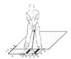
- FIG. 1 is a perspective view of a golfer practicing by attaching the present invention to the general practice golf mat.
- FIG. 2 is a perspective view of the folded shape of the present invention.
- FIG. 3A is a top view showing incorrect impact.
- the golf club head makes an in-to-out path.
- FIG. 3B is a top view showing one of the perfect impact conditions which the club head must hit the ball in a parallel direction to the target point.
- FIG. 3C is a top view showing incorrect impact.
- the golf club head makes an out-to-in path.
- FIG. 4A is a side view showing incorrect impact. The golf club head hit the golf mat first.
- FIG. 4B is a side view showing one of the perfect impact conditions which the golf club head must hit the ball directly without contacting the golf mat, first.
- FIG. 4C is a side view showing incorrect impact.
- the golf club head makes a topping ball.
- FIG. 5A is a top view showing incorrect impact.
- the golf club face is open.
- FIG. 5B is a top view showing one of the perfect impact conditions which the club face must contact with the ball at the right angle to the target direction.
- FIG. 5C is a top view showing incorrect impact. The golf club face is closed.
- FIG. 6 is a side view for explaining a process in which the wire-activating switch is activated when the golf club head hit the detecting-wire, and it is showing a state before the detecting-wire is activated.
- FIG. 6A is a side view showing a state that the detecting-wire is activated by the golf club head passed through the impact area.
- FIG. 7 is a top view for explaining a process in which the wire-activating switch is activated when the golf club head hit the detecting-wire, and it is showing a state before the detecting-wire is activated.
- FIG. 7A is a top view showing a process that the LED lights are emitting after the club head passed through the swing path sensor assembly and these are indicating the swing path accurately by emitted lights from front sensor bar and rear sensor bar.
- FIG. 8 is a fragmentary side view for explaining that the wire-activating switch is activated when the golf club head hit the detecting-wire, and it is showing inside the wire-activating switch with the detecting wire which is sticking out the golf mat.
- FIG. 8A is a fragmentary side view to explain a process that the LED light is emitted when the golf club head is hitting the detecting wire, and it is showing a movement of the flexible terminal.
- FIG. 9 is a fragmentary side view for explaining a process that the fat shot sensor assembly is detecting when the golf club head hits the golf mat in front of the ball and it is showing inside of the fat shot sensor assembly with two limit switches.
- FIG. 9A is a fragmentary side view showing that the limit switches in the fat shot sensor assembly are activating when the golf club head is hitting the golf mat in front of the ball and the lights on the control box are emitting.
- FIG. 9B is a perspective view, showing where the fat shot sensor assemblies is located.
- FIG. 10 is a side view showing a process of measuring a speed of the golf club head and indicating it. It measures accurately the speed of the club head by difference of the touching time between the front detecting-wires and the rear detecting-wires.
- FIG. 11 is a schematic drawing to illustrate the structure of the present invention and the location of all parts.
- FIG. 11A is a perspective view of the wire-activating switch.
- FIG. 11B is a perspective view showing a process of forming a sensor bar by connecting the wire-activating switches consecutively.
- the present invention is made with similar material as the mats provided at the public golf driving range. Golfers will be find this invention familiar and will adjust to it quickly.
- This invention is designed to be used by attaching to the general golf practice mat or a private golf mat and is designed to fold in half so as to be easily carried with in hand. (refer to FIG. 1 and FIG. 2 )
- the portable golf impact practice mat comprising:
- the two critical components in the game of golf are the swing and the moment of impact in a swing.
- the key features of the present invention is to indicate immediately and accurately three important impact conditions through the light emitting device and the digital display, and these devices are mounted inside the control box 75 and underneath the golf mat 54 around the impact area 54 - 1 . Indicating the critical information about the swing, this invention will help improve the swing technique of many golfers.
- Portability is another key feature of this invention. It was designed to be portable because every golfer should be able to use it easily. It would not be feasible for this invention to be the same size as the mats found in public/private driving ranges so this invention was designed to be folded in half. Even though it is smaller than the traditional golf mat, it retains similar attributes as a traditional golf mat. This invention retains similar material and similar height to a traditional mat. It is designed not to be a replacement to a traditional golf mat but rather an add-on device that attaches itself to a golf mat. The easy integration to a traditional mat will provide familiarity and an illusion that the invention is a part of the golf mat. The material for the invention is flexible and can be scale with any new material developed for golf mats.
- the present invention is divided by the impact area side part and the other side part, by the folding part of the bisected-frame members 55 .
- Most of the sensors are mounted in the bottom layer of the impact area side part.
- the bottom layer of the other side part is a residual extra space, can use the space as a container to store some extra tools and related parts, by creating a box with the same height as the sensors height of the impact area part.
- the upper layer is conforms with same material as general golf mats that using at public golf driving ranges and the mats on the impact area side part have a plurality of perforated holes 53 for sticking out the detecting-wires 63 from the swing path sensor assembly, and have a plurality of perforated holes 53 for emitting LED lights 64 .
- a plurality of holes 53 on the mat should be the elongated shape in order to do not affect the movement of the detecting-wires 63 because the detecting-wires 63 move to the target direction by hitting with the club head.
- the area around the perforated holes 53 should be strengthened because the holes 53 are too close to each other, and the frequently hitting area by the club. Thus, it needs to be reinforced this area with a very strong and flexible materials a kind of polyurethane or a stronger and soft similar materials.
- a ball position 52 needs to be constant because it is related in determining the swing path.
- a rubber golf tee can be mounted in the middle of the impact area 54 - 1 , or it needs to mark a ball position 52 in the center of the impact area 54 - 1 .
- the golf mat 54 of the impact area 54 - 1 is easy to be worn out, should be designed to be able to replace easily using the Velcro.
- the sensor assemblies that needed to analyze a golf impact conditions using the present invention are the swing path sensor assembly and the fat shot sensor assembly 61 .
- the swing path sensor assembly also has a function of detecting a golf club head speed.
- FIG. 11A is a perspective view showing the structure of the wire-activating switch 62 .
- the wire-activating switch 62 is the primary sensor of the present invention.
- a LED (light emitting diode) 64 and a resistor which are light emitting elements are mounted inside of the wire-activating switch 62 and it will emit the light when the detecting-wire 63 is activated by hitting with the club head 71 .
- the detecting-wire 63 is connected from inside of the wire-activating switch 62 toward to upper direction, and sticking out through a perforated hole 53 on the golf mat 54 . It is moved 72 to the target direction by hitting it with the club head 71 and it is activated a swing path signal lights, and measure the club head speed.
- the first switching operation of the wire-activating switch 62 is as shown in the FIG. 8 , FIG. 8A , when the club head 71 hits the detecting-wires 63 , the detecting-wire 63 is moved to the target direction, the sliding-parts 70 is moved along the detecting-wires 63 , and a thin flexible terminal 68 is connected with the bottom terminal 67 through the thin curved passage of the sliding parts 70 , and the LED light 64 emit by contact.
- the flexible terminal 68 and the bottom terminal 67 should be used a high electrical conductivity metals which can be go through the electricity very well, like a copper or a brass because it has a weak contact by structural characteristics of this switch.
- the thin flexible-terminal 68 should be moved smoothly along the thin curved passage of the sliding parts 70 , so it should be used very good resilience and electrical conductivity metals.
- the sensor bar 60 comprises a series of the wire-activating switches 62 connected consecutively, and a pair of the sensor bars 60 composes a swing path sensor assembly, will indicate the path of the club head 71 .
- One sensor bar 60 is disposed in front of the impact area 54 - 1 based on the target direction and the other is disposed behind the impact area 54 - 1 , both are covered with the golf mat 54 .
- the detecting-wires 63 are sticking out from the inside of the wire-activating switches 62 toward to upper direction through a plurality of perforated holes 53 on the golf mat, will detects a golf club head 71 .
- the club head hits the detecting-wires 63 from the front sensor bar 60 , the ball, and then the detecting-wires 63 from the rear sensor bar 60 .
- the detecting-wires 63 By hitting the detecting-wires 63 with the club head 71 during the swing, the corresponding LED lights 64 are emitted, and the front and rear emitted LED lights 64 show the club head 71 movements accurately.
- the club head 71 In order to create a perfect impact that I mentioned earlier, the club head 71 must be traveled in a parallel direction to the target point. ( FIG. 3B ) If the club head 71 makes an out-to-in path ( FIG. 3A ), or in-to-out path, ( FIG. 3C ), it will make a spin a ball and the ball flight will be fade/slice or draw/hook respectively. And it tends to lose distance if the ball is not hit in a parallel to the target point.
- the other switching operation of the wire-activating switch 62 is to measure the club head speed. It measures accurately the speed of the club head 71 by the difference of the touching time between the front sensor bar 60 and the rear sensor bar 60 . Obviously, the faster club head moves, further the ball flies. The first shot from the tee box is very important, and it will be advantageous to send a ball accurate and farther.
- the wire-activating switches 62 are fully protected underneath the golf mat, these are located in around a frequently hitting area. Therefore, the wire-activating switch 62 should be made of the material that is sturdy, abrasion durable and withstanding from hitting hard.
- the detecting-wires 63 connected from the wire-activating switches 62 are hit frequently and strongly by the golf club. Thus, they should make of a very strong and a good elasticity/soft material such as a fishing wire and should designed to replace easily in case of broken.
- the fat shot sensor assembly 61 that detects a fat shot, is located underneath the golf mat around the impact area 54 - 1 . It will activate the signal generating unit by the sensors 74 in the fat shot sensor assembly 61 , if the club head 71 hits the golf mat 54 before it makes contact with the ball known as a fat shot.
- the signal generating unit includes a speaker for generating a sound signal, the notification lamp 76 for generating a light signal using light.
- the signal generating unit is provided with both the notification lamp 76 and the speaker or may be provided with either one of the notification lamp 76 and the speaker.
- This fat shot sensor assembly 61 is required a device that allows to adjust the sensing intensity of the sensors 74 . Considering the rough area, It must be designed not to be affected, even if hit very strongly by a club head 71 or accidentally stepping on. The goal here is to hit the ball first before the club head hits the golf mat. Therefore, one should practice not to generate this notification lamp 74 .
- a fat shot greatly reduces the speed of the club, which reduces the speed of the ball and in turn decreases the distance the ball will travel.
- the present invention thus shows the swing path, club head speed, and fat impact condition at the same time.
- Another thing that must be executed to achieve a perfect impact is that the club face must contact the ball at the right angle to the target point. (refer to FIG. 5 ) And it should find a golfer's grip by changing the grip by itself to make the club face at a right angle. It is also an extremely important point. Besides these, it can be reset simply by pushing the reset button 78 , or by auto reset function that automatically reset under specific conditions set by the golfer for his/her convenience.
- the battery and a power source such as a secondary battery is built in the control box 75 , and for the apparatus used in the indoor golf driving range is preferably formed to be connected with a separate adapter.
Landscapes
- Engineering & Computer Science (AREA)
- Health & Medical Sciences (AREA)
- General Health & Medical Sciences (AREA)
- Physical Education & Sports Medicine (AREA)
- Multimedia (AREA)
- Human Computer Interaction (AREA)
- Computer Vision & Pattern Recognition (AREA)
- Physics & Mathematics (AREA)
- General Physics & Mathematics (AREA)
- Theoretical Computer Science (AREA)
- Golf Clubs (AREA)
Abstract
The portable golf impact practice mat is a golf practice mat that provides visual indicators to inform of three extremely important impact conditions using a digital display, a signal generating unit and a plurality of LED (light emitting diode). One of them indicates the swing path in reference to how the golf club head moves toward the target. Another detects and indicates if the club head hits the golf mat in front of the ball also known as a “fat shot”. Lastly, the third displays a club head speed upon impact. The present invention is designed to be used by attaching to the general golf practice mats widely found in public golf driving ranges or personal golf practice mats. The present invention is compact, folds in half and fits in one-hand providing portability.
Description
The present invention relates to a portable golf swing practice mat and, more particularly, to an attachable correct impact practice mat including three indicators to inform three impact conditions, indicating a path of the golf club head, indicating a detected fat shot and displaying a swing speed.
The game of golf is to put a golf ball into a series of the hole cups, starting from certain points known as a “tee box” located on various distances. The player uses various golf clubs in as few strokes as possible, during the game. To achieve this goal and place the ball into a hole in as few strokes as possible, a longer and more accurate golf shot is extremely important. In fact, many amateur golfers are focusing on a swing technique for power rather than a swing technique of how to make a correct impact. For example, some teenage boys and girls who want to be professional golfers are hitting a ball farther and more accurate than general adult golfers do, even though they are physically weaker. This proves the point that it is more important for a swing technique focusing on correct impact rather than a swing technique of power. Without realizing this point, most amateur golfers are practicing a lot to improve their swings but it is not improve because they are still focus on the swing technique of hitting the ball more powerfully.
Many golfers have no idea what their swing flaws are, because they don't have any information about the moment of contact in when the club head meets the ball. Most would follow instructions from a golf teaching professional without fully understanding the reason behind it.
The opportunity to invent this apparatus was derived from the idea that if there was a device that could provide accurate indication during the golf ball impact of the golf swing, many golfers will improve the techniques efficiently in a short period of time. Golfers, who use the present invention, will improve their swing easily by receiving feedback of the golf swing immediately through the indicators. The present invention also will help augment any adjustments from golf teaching professionals in order to create the “perfect swing”.
According to science, there must be four conditions met to achieve the perfect impact on the golf swing:
First, the club head must hit the ball in a parallel direction to the target point. (refer to FIG. 3B )
Second, the club head must hit the ball directly without hitting the ground, first. (refer to FIG. 4B )
Third, the club face must contact with the ball at the right angle to the target direction. (refer to FIG. 5B )
Fourth, faster head speed will give a greater distance to the ball travel.
First, second and third are required conditions to achieve a perfect impact.
First, second, third and fourth are required conditions to send a ball more accurate and farther.
All golfers aspire to send a ball farther away or accurately to the desired distance and most golfers expend a lot of time and effort in developing a golf swing in order to obtain this result. But, it does not effectively improve, because most of them do not realize of the fact that there are many difference between the imagined swing that they wanted to do and an actual performed swing.
The present invention has three indicators to inform the golfer of three extremely important impact conditions. One of them indicates a path of the golf club head as that how the golf club head moves toward the target. Another indicates if the club head hits the golf mat before contact with the ball. Lastly, a third displays the club head speed. These indicators will show user's swing conditions accurately and will provide direction to where they need to adjust, by disclosing flaws in their swing. This would especially help golfers who do not see improvements despite the countless hours they exert in practicing the golf swing. The present invention would be an absolute must for novice golfers as they can leverage this invention to learn the correct swing from the beginning. This invention was designed with portability in mind to provide a practical device that is simple to use and convenient.
Some prior art were developed with a method of indicating the movement of golf club head using the mat made by special materials, but It was durable for prolonged use. Other prior art utilizes complicated apparatus and is only provided in specialized facilities. One prior art, in the case of video analyzer, which provides a way to calibrate and analyze a swing by reviewing the recorded information recorded with the video analyzer can provide similar results but it less effective because the swing can't be checked in real-time.
The present invention is made with similar material as the mats provided at the public golf driving range. Golfers will be find this invention familiar and will adjust to it quickly. This invention is designed to be used by attaching to the general golf practice mat or a private golf mat and is designed to fold in half so as to be easily carried with in hand. (refer to FIG. 1 and FIG. 2 )
The portable golf impact practice mat, comprising:
-
- 1. A swing path sensor assembly having two
equal sensor bar 60, thesensor bar 60 further comprises a series of the wire-activatingswitches 62 connected consecutively, onesensor bar 60 is disposed in front of the impact area 54-1 based on the target direction and the other is disposed behind, both are covered with thegolf mat 54. A plurality of the detectingwires 63 are sticking out from inside of the wire-activatingswitches 62, which are major members of the swing path sensor assembly, toward the upper direction through a plurality ofperforated holes 53 on thegolf mat 54, in purpose of detecting agolf club head 71. - 2. A fat
shot sensor assembly 61 having at least twosensors 74 detect that theclub head 71 hits thegolf mat 54 in front of the ball known as a fat shot, are disposed around theimpact area 51 and covered with thegolf mat 54. - 3. A head speed sensors detecting the speed of the
club head 71 by the difference of the touching time between the front detectingwires 63 and therear detecting wires 63, are disposed inside of the wire-activatingswitches 62. - 4. A
perforated golf mat 54 having a plurality ofholes 53 for sticking out the detecting-wires 63 from the swing path sensor assembly and for emitting LED lights 64, formed an artificial turf like a general golf mat and is disposed upper of the impact area 54-1. - 5. A
spacer plate 56 aligning equal height with other side, is disposed bottom layer of other side of the impact area 54-1, and may be created as a container used for storage to put some handy tools and extra related parts. - 6. A
golf mat 54 forming an artificial turf like a general golf mat, is disposed above thespacer plate 56 at the other side of the impact area 54-1. - 7. A pair of longer
side frame members 55 supporting both of longer sides of theentire golf mat 54, 54-1 which shaped a long rectangular, is approximately the same height as thegolf mat 54, and is made of a steel bar. Both are the bisected-frame members 55 which connected 59 to be able to fold in half, to make as a portable. - 8. A pair of shorter
side frame members extension bar 57 each including aclamp 58 in purpose of attaching on a general golf mat, is approximately the same height as thegolf mat 54, and is made of a thin steel bar. - 9. A
control box 75 having theclub head 71speed indicator 77, the fat shotindicator 76, areset button 78, batteries, a secondary battery,power switch 79, circuit, some control switches and the like.
- 1. A swing path sensor assembly having two
The two critical components in the game of golf are the swing and the moment of impact in a swing. The key features of the present invention is to indicate immediately and accurately three important impact conditions through the light emitting device and the digital display, and these devices are mounted inside the control box 75 and underneath the golf mat 54 around the impact area 54-1. Indicating the critical information about the swing, this invention will help improve the swing technique of many golfers.
Portability is another key feature of this invention. It was designed to be portable because every golfer should be able to use it easily. It would not be feasible for this invention to be the same size as the mats found in public/private driving ranges so this invention was designed to be folded in half. Even though it is smaller than the traditional golf mat, it retains similar attributes as a traditional golf mat. This invention retains similar material and similar height to a traditional mat. It is designed not to be a replacement to a traditional golf mat but rather an add-on device that attaches itself to a golf mat. The easy integration to a traditional mat will provide familiarity and an illusion that the invention is a part of the golf mat. The material for the invention is flexible and can be scale with any new material developed for golf mats.
The present invention is divided by the impact area side part and the other side part, by the folding part of the bisected-frame members 55. Most of the sensors are mounted in the bottom layer of the impact area side part. And the bottom layer of the other side part is a residual extra space, can use the space as a container to store some extra tools and related parts, by creating a box with the same height as the sensors height of the impact area part. The upper layer is conforms with same material as general golf mats that using at public golf driving ranges and the mats on the impact area side part have a plurality of perforated holes 53 for sticking out the detecting-wires 63 from the swing path sensor assembly, and have a plurality of perforated holes 53 for emitting LED lights 64. Especially, a plurality of holes 53 on the mat should be the elongated shape in order to do not affect the movement of the detecting-wires 63 because the detecting-wires 63 move to the target direction by hitting with the club head. The area around the perforated holes 53 should be strengthened because the holes 53 are too close to each other, and the frequently hitting area by the club. Thus, it needs to be reinforced this area with a very strong and flexible materials a kind of polyurethane or a stronger and soft similar materials.
A ball position 52 needs to be constant because it is related in determining the swing path. Thus, a rubber golf tee can be mounted in the middle of the impact area 54-1, or it needs to mark a ball position 52 in the center of the impact area 54-1. In particular, since the golf mat 54 of the impact area 54-1 is easy to be worn out, should be designed to be able to replace easily using the Velcro. The sensor assemblies that needed to analyze a golf impact conditions using the present invention are the swing path sensor assembly and the fat shot sensor assembly 61. The swing path sensor assembly also has a function of detecting a golf club head speed.
The sensor bar 60 comprises a series of the wire-activating switches 62 connected consecutively, and a pair of the sensor bars 60 composes a swing path sensor assembly, will indicate the path of the club head 71. One sensor bar 60 is disposed in front of the impact area 54-1 based on the target direction and the other is disposed behind the impact area 54-1, both are covered with the golf mat 54. The detecting-wires 63 are sticking out from the inside of the wire-activating switches 62 toward to upper direction through a plurality of perforated holes 53 on the golf mat, will detects a golf club head 71. As a golfer performs his/her swing, the club head hits the detecting-wires 63 from the front sensor bar 60, the ball, and then the detecting-wires 63 from the rear sensor bar 60. By hitting the detecting-wires 63 with the club head 71 during the swing, the corresponding LED lights 64 are emitted, and the front and rear emitted LED lights 64 show the club head 71 movements accurately.
In order to create a perfect impact that I mentioned earlier, the club head 71 must be traveled in a parallel direction to the target point. (FIG. 3B ) If the club head 71 makes an out-to-in path (FIG. 3A ), or in-to-out path, (FIG. 3C ), it will make a spin a ball and the ball flight will be fade/slice or draw/hook respectively. And it tends to lose distance if the ball is not hit in a parallel to the target point.
The other switching operation of the wire-activating switch 62 is to measure the club head speed. It measures accurately the speed of the club head 71 by the difference of the touching time between the front sensor bar 60 and the rear sensor bar 60. Obviously, the faster club head moves, further the ball flies. The first shot from the tee box is very important, and it will be advantageous to send a ball accurate and farther. Although the wire-activating switches 62 are fully protected underneath the golf mat, these are located in around a frequently hitting area. Therefore, the wire-activating switch 62 should be made of the material that is sturdy, abrasion durable and withstanding from hitting hard. Also, the detecting-wires 63 connected from the wire-activating switches 62 are hit frequently and strongly by the golf club. Thus, they should make of a very strong and a good elasticity/soft material such as a fishing wire and should designed to replace easily in case of broken.
Lastly, the fat shot sensor assembly 61 that detects a fat shot, is located underneath the golf mat around the impact area 54-1. It will activate the signal generating unit by the sensors 74 in the fat shot sensor assembly 61, if the club head 71 hits the golf mat 54 before it makes contact with the ball known as a fat shot.
The signal generating unit includes a speaker for generating a sound signal, the notification lamp 76 for generating a light signal using light. The signal generating unit is provided with both the notification lamp 76 and the speaker or may be provided with either one of the notification lamp 76 and the speaker. This fat shot sensor assembly 61 is required a device that allows to adjust the sensing intensity of the sensors 74. Considering the rough area, It must be designed not to be affected, even if hit very strongly by a club head 71 or accidentally stepping on. The goal here is to hit the ball first before the club head hits the golf mat. Therefore, one should practice not to generate this notification lamp 74. A fat shot greatly reduces the speed of the club, which reduces the speed of the ball and in turn decreases the distance the ball will travel.
The present invention thus shows the swing path, club head speed, and fat impact condition at the same time. One can self-analyze his/her swing, and therefore modify the swing immediately, and can be improved the swing much quickly and accurately, by repeating. Another thing that must be executed to achieve a perfect impact is that the club face must contact the ball at the right angle to the target point. (refer to FIG. 5 ) And it should find a golfer's grip by changing the grip by itself to make the club face at a right angle. It is also an extremely important point. Besides these, it can be reset simply by pushing the reset button 78, or by auto reset function that automatically reset under specific conditions set by the golfer for his/her convenience.
The battery and a power source such as a secondary battery is built in the control box 75, and for the apparatus used in the indoor golf driving range is preferably formed to be connected with a separate adapter.
In conclusion, with respect to the above description, it is to be understood that the optimal dimensional specifications for the parts of the invention, including variations in number, size, shape, form, placement, material and the method of fabrication and assembly are deemed readily apparent to persons skilled in the art upon a reading of the foregoing description, and all equivalent specifications to those illustrated in the drawings and detailed in the description are intended to be encompassed by the present invention. Furthermore, it will be obvious to those skilled in the art that various modifications and revisions can be made to the embodiment shown herein without departing from the spirit and essential characteristics of the invention. It is therefore intended by the appended claims to cover any and all such modifications and revisions within the scope of the present invention.
Claims (20)
1. A portable golf impact practice mat, comprising:
an impact area for placing a golf ball to be hit;
a first sensor bar and a second sensor bar for detecting swing path and swing speed of a golf club head that is hitting the golf ball, where the first sensor bar and the second sensor bar are placed on or close to two sides of the impact area and is configured in a way that when a golf ball and pass the second sensor bar in sequence;
at least one pressure sensor is placed beneath the impact area for detecting whether a fat shot occurred;
a control box that connects to the first sensor bar, the second sensor bar and the at least one pressure sensor, where the control box calculates and displays the swing speed of the golf club head and indicates whether a fat shot occurred; and
wherein the impact area further comprises plurality of perforated holes with LED lights that identifies the swing path of the golf club head.
2. The portable golf impact practice mat according to claim 1 , wherein the first sensor bar and the second sensor bar are parallel to each other and each comprises a series of wire-activating switches connected consecutively in a line, and each wire-activating switch has a wire that extends above the impact area.
3. The portable golf impact practice mat according to claim 2 , wherein the wire activates the wire-activating switch when the wire is contacted by the golf club head.
4. The portable golf impact practice mat according to claim 3 , wherein the swing path of the golf club head is detected based on the activation of wire-activating switch or switches on the first sensor bar and the second sensor bar.
5. The portable golf impact practice mat according to claim 3 , wherein each wire-activating switch is coupled with a LED light that emits light through on of the plurality of perforated holes when the wire-activating switch is being activated.
6. The portable golf impact practice mat according to claim 1 , wherein the control box further comprises a speed indicator, a fat shot indicator, a power switch and a reset button.
7. The portable golf impact practice mat according to claim 1 , wherein the first sensor bar, the second sensor bar, the at least one pressure sensor and the control box are powered by batteries in the control box or through a separate adapter.
8. The portable golf impact practice mat according to claim 1 , further comprises at least one clamp for clamping the portable golf impact practice mat to another golf mat.
9. The portable golf impact practice mat according to claim 3 , wherein the swing speed of a golf club head is calculated based on a distance between the first sensor bar and the second sensor bar, and based on a time between activation of wire-activating switch or switches on the first sensor bar and the activation of wire-activating switch or switches on the second sensor bar.
10. A portable golf impact practice mat, comprising:
an impact area for placing a golf ball to be hit;
a first sensor bar and a second sensor bar for detecting swing path and swing speed of a golf club head that is hitting the golf ball, where the first sensor bar and the second sensor bar are placed on or close to two sides of the impact area and is configured in a way that when a golf club swings at the golf ball, the golf club head will pass the first sensor bar, pass or hit the golf ball and pass the second sensor bar in sequence;
wherein the first sensor bar and the second sensor bar are parallel to each other and each comprises a series of wire-activating switches connected consecutively in a line, and each wire-activating switch is coupled to a LED light and has a wire that extends above the impact area,
wherein each wire-activating switch is activated when its wire is in contact with the golf club head and its LED light will emit light through a perforated hole on the impact area;
wherein the swing path of the golf club head is identified by LED lights based on which wire-activating switches are being activated in the first sensor bar and the second sensor bar;
at least one pressure sensor is placed beneath the impact area for detecting whether a fat shot occurred; and
a control box that connects to the first sensor bar, the second sensor bar and the at least one pressure sensor, where the control box calculates and displays the swing speed of the golf club head through a speed indicator and indicates whether a fat shot occurred through a fat shot indicator.
11. The portable golf impact practice mat according to claim 10 , wherein the control box further comprises a power switch and a reset button.
12. The portable golf impact practice mat according to claim 10 , wherein the first sensor bar, the second sensor bar, the at least one pressure sensor and the control box are powered by batteries in the control box.
13. The portable golf impact practice mat according to claim 10 , further comprises at least one clamp for clamping the portable golf impact practice mat to another golf mat.
14. The portable golf impact practice mat according to claim 10 , wherein the swing speed of a golf club head is calculated based on a distance between the first sensor bar and the second sensor bar, and based on a time between activation of wire-activating switch or switches on the first sensor bar and the activation of wire-activating switch or switches on the second sensor bar.
15. The portable golf impact practice mat according to claim 10 , further comprises a foldable golf mat that connects to the impact area through a hinge and is configured in a way that the foldable golf mat can be folded to the impact area or unfolded from the impact area.
16. A portable golf impact practice mat, comprising:
an impact area for placing a golf ball to be hit;
a first sensor bar and a second sensor bar for detecting swing path and swing speed of a golf club head that is hitting the golf ball, where the first sensor bar and the second sensor bar are placed on two sides of the impact area and is configured in a way that when a golf club swings at the golf ball, the golf club head will pass the first sensor bar, pass or hit the golf ball and pass the second sensor bar in sequence;
wherein the first sensor bar and the second sensor bar are parallel to each other and each comprises a series of wire-activating switches connected consecutively in a line, and each wire-activating switch is coupled to a LED light and has a wire that extends above the impact area;
wherein each wire-activating switch is activated when its wire is in contact with the golf club head and its LED light will emit light through a perforated hole on the impact area;
wherein the swing path of the golf club head is identified by LED lights based on which wire-activating switches are being activated in the first sensor bar and the second sensor bar;
at least one pressure sensor is placed beneath the impact area for detecting whether a fat shot occurred;
a control box that calculates and displays the swing speed of the golf club head and indicates whether a fat shot occurred; and
a foldable golf mat that connects to the impact area through a hinge and is configured in a way that the foldable golf mat can be folded to the impact area or unfolded from the impact area.
17. The portable golf impact practice mat according to claim 16 , wherein the control box further comprises a power switch and a reset button.
18. The portable golf impact practice mat according to claim 16 , wherein the first sensor bar, the second sensor bar, the at least one pressure sensor and the control box are powered by batteries in the control box.
19. The portable golf impact practice mat according to claim 16 , further comprises at least one clamp for clamping the portable golf impact practice mat to a general golf mat.
20. The portable golf impact practice mat according to claim 16 , wherein the swing speed of a golf club head is calculated based on a distance between the first sensor bar and the second sensor bar, and based on a time between activation of wire-activating switch or switches on the first sensor bar and the activation of wire-activating switch or switches on the second sensor bar.
Priority Applications (2)
| Application Number | Priority Date | Filing Date | Title |
|---|---|---|---|
| US14/737,391 US9517399B1 (en) | 2015-06-11 | 2015-06-11 | Portable golf impact practice mat |
| PCT/US2016/035932 WO2016200706A1 (en) | 2015-06-11 | 2016-06-04 | Portable golf impact practice mat |
Applications Claiming Priority (1)
| Application Number | Priority Date | Filing Date | Title |
|---|---|---|---|
| US14/737,391 US9517399B1 (en) | 2015-06-11 | 2015-06-11 | Portable golf impact practice mat |
Publications (2)
| Publication Number | Publication Date |
|---|---|
| US9517399B1 true US9517399B1 (en) | 2016-12-13 |
| US20160361618A1 US20160361618A1 (en) | 2016-12-15 |
Family
ID=57483892
Family Applications (1)
| Application Number | Title | Priority Date | Filing Date |
|---|---|---|---|
| US14/737,391 Expired - Fee Related US9517399B1 (en) | 2015-06-11 | 2015-06-11 | Portable golf impact practice mat |
Country Status (2)
| Country | Link |
|---|---|
| US (1) | US9517399B1 (en) |
| WO (1) | WO2016200706A1 (en) |
Citations (7)
| Publication number | Priority date | Publication date | Assignee | Title |
|---|---|---|---|---|
| US3601408A (en) * | 1969-10-13 | 1971-08-24 | Kenneth K Wright | Golf swing training apparatus |
| US3936055A (en) * | 1974-12-11 | 1976-02-03 | Joseph B. Michaelson | Golf practice device |
| US4254956A (en) * | 1978-11-21 | 1981-03-10 | Rusnak Thomas L | Golf swing training apparatus |
| US6135895A (en) * | 1999-08-23 | 2000-10-24 | Estivo; Robert | Golf training system |
| US6227984B1 (en) * | 1998-05-01 | 2001-05-08 | Charles H. Blankenship | Golf swing analysis methods |
| US20030054898A1 (en) * | 2001-09-14 | 2003-03-20 | Otten Leslie B. | Sport swing analysis system |
| US7704154B2 (en) * | 2008-01-09 | 2010-04-27 | Cheng Wah Loh | Golf swing trainer |
-
2015
- 2015-06-11 US US14/737,391 patent/US9517399B1/en not_active Expired - Fee Related
-
2016
- 2016-06-04 WO PCT/US2016/035932 patent/WO2016200706A1/en active Application Filing
Patent Citations (7)
| Publication number | Priority date | Publication date | Assignee | Title |
|---|---|---|---|---|
| US3601408A (en) * | 1969-10-13 | 1971-08-24 | Kenneth K Wright | Golf swing training apparatus |
| US3936055A (en) * | 1974-12-11 | 1976-02-03 | Joseph B. Michaelson | Golf practice device |
| US4254956A (en) * | 1978-11-21 | 1981-03-10 | Rusnak Thomas L | Golf swing training apparatus |
| US6227984B1 (en) * | 1998-05-01 | 2001-05-08 | Charles H. Blankenship | Golf swing analysis methods |
| US6135895A (en) * | 1999-08-23 | 2000-10-24 | Estivo; Robert | Golf training system |
| US20030054898A1 (en) * | 2001-09-14 | 2003-03-20 | Otten Leslie B. | Sport swing analysis system |
| US7704154B2 (en) * | 2008-01-09 | 2010-04-27 | Cheng Wah Loh | Golf swing trainer |
Also Published As
| Publication number | Publication date |
|---|---|
| WO2016200706A1 (en) | 2016-12-15 |
| US20160361618A1 (en) | 2016-12-15 |
Similar Documents
| Publication | Publication Date | Title |
|---|---|---|
| US7641565B2 (en) | Method and apparatus for detecting the placement of a golf ball for a launch monitor | |
| KR101967324B1 (en) | Divot detectable golf swing mat | |
| US7540500B2 (en) | Foldable launch monitor for golf | |
| US7497780B2 (en) | Integrated golf ball launch monitor | |
| US9586122B2 (en) | Golf putting trainer device | |
| US9604117B2 (en) | Golf stroke training device | |
| US20090082122A1 (en) | Sporting club swing trainer | |
| JPH03258273A (en) | Training gold device | |
| US10046200B2 (en) | Height target scoring device | |
| US8465377B1 (en) | Golf putting training aid | |
| EP2032220B1 (en) | Method and apparatus for detecting the placement of a golf ball for a launch monitor | |
| US3801108A (en) | Golfer{40 s wrist-release detector | |
| JP2008539847A (en) | Putting practice aids | |
| KR102019760B1 (en) | Apparatus for golf putting practice | |
| KR20020023720A (en) | Indicating system of portable golf swing trainer | |
| US9517399B1 (en) | Portable golf impact practice mat | |
| KR0129095B1 (en) | A golf swing analyzer | |
| KR101599408B1 (en) | Apparatus for practicing golf putting | |
| KR200398717Y1 (en) | Electronic Putting Trainer | |
| US20170326427A1 (en) | Golf swing teaching device | |
| KR200418102Y1 (en) | Switch box for golf range | |
| JP2017127542A (en) | Golf training device | |
| KR101570007B1 (en) | Swing training apparatus | |
| US11794086B2 (en) | Golf putting training system and method | |
| KR200376253Y1 (en) | Device for exercising swing golf |
Legal Events
| Date | Code | Title | Description |
|---|---|---|---|
| STCF | Information on status: patent grant |
Free format text: PATENTED CASE |
|
| FEPP | Fee payment procedure |
Free format text: MAINTENANCE FEE REMINDER MAILED (ORIGINAL EVENT CODE: REM.); ENTITY STATUS OF PATENT OWNER: SMALL ENTITY |
|
| LAPS | Lapse for failure to pay maintenance fees |
Free format text: PATENT EXPIRED FOR FAILURE TO PAY MAINTENANCE FEES (ORIGINAL EVENT CODE: EXP.); ENTITY STATUS OF PATENT OWNER: SMALL ENTITY |
|
| STCH | Information on status: patent discontinuation |
Free format text: PATENT EXPIRED DUE TO NONPAYMENT OF MAINTENANCE FEES UNDER 37 CFR 1.362 |
|
| FP | Lapsed due to failure to pay maintenance fee |
Effective date: 20201213 |