US9500453B2 - Wad with ignition chamber - Google Patents
Wad with ignition chamber Download PDFInfo
- Publication number
- US9500453B2 US9500453B2 US14/455,673 US201414455673A US9500453B2 US 9500453 B2 US9500453 B2 US 9500453B2 US 201414455673 A US201414455673 A US 201414455673A US 9500453 B2 US9500453 B2 US 9500453B2
- Authority
- US
- United States
- Prior art keywords
- ignition
- ignition chamber
- wad
- tube
- primer
- Prior art date
- Legal status (The legal status is an assumption and is not a legal conclusion. Google has not performed a legal analysis and makes no representation as to the accuracy of the status listed.)
- Active, expires
Links
- 239000003380 propellant Substances 0.000 claims abstract description 61
- 230000008901 benefit Effects 0.000 abstract description 10
- 239000000843 powder Substances 0.000 description 42
- 239000007789 gas Substances 0.000 description 28
- 229910000831 Steel Inorganic materials 0.000 description 17
- 239000010959 steel Substances 0.000 description 17
- 238000010304 firing Methods 0.000 description 13
- 239000008188 pellet Substances 0.000 description 11
- 239000000463 material Substances 0.000 description 10
- 230000001965 increasing effect Effects 0.000 description 9
- 230000009467 reduction Effects 0.000 description 5
- 241000272517 Anseriformes Species 0.000 description 4
- 239000000853 adhesive Substances 0.000 description 3
- 230000001070 adhesive effect Effects 0.000 description 3
- 230000003247 decreasing effect Effects 0.000 description 3
- 238000006073 displacement reaction Methods 0.000 description 3
- 230000002349 favourable effect Effects 0.000 description 3
- 238000013101 initial test Methods 0.000 description 3
- 238000007789 sealing Methods 0.000 description 3
- 229910001369 Brass Inorganic materials 0.000 description 2
- 230000001133 acceleration Effects 0.000 description 2
- 239000010951 brass Substances 0.000 description 2
- 238000010276 construction Methods 0.000 description 2
- 230000002708 enhancing effect Effects 0.000 description 2
- 239000011888 foil Substances 0.000 description 2
- 238000003306 harvesting Methods 0.000 description 2
- 239000002184 metal Substances 0.000 description 2
- 229910052751 metal Inorganic materials 0.000 description 2
- 239000004033 plastic Substances 0.000 description 2
- 229920003023 plastic Polymers 0.000 description 2
- XQMVBICWFFHDNN-UHFFFAOYSA-N 5-amino-4-chloro-2-phenylpyridazin-3-one;(2-ethoxy-3,3-dimethyl-2h-1-benzofuran-5-yl) methanesulfonate Chemical compound O=C1C(Cl)=C(N)C=NN1C1=CC=CC=C1.C1=C(OS(C)(=O)=O)C=C2C(C)(C)C(OCC)OC2=C1 XQMVBICWFFHDNN-UHFFFAOYSA-N 0.000 description 1
- 238000007792 addition Methods 0.000 description 1
- 229920002678 cellulose Polymers 0.000 description 1
- 239000001913 cellulose Substances 0.000 description 1
- 230000008859 change Effects 0.000 description 1
- 230000007423 decrease Effects 0.000 description 1
- 230000009977 dual effect Effects 0.000 description 1
- 230000000694 effects Effects 0.000 description 1
- 230000007613 environmental effect Effects 0.000 description 1
- 230000006870 function Effects 0.000 description 1
- 229920001903 high density polyethylene Polymers 0.000 description 1
- 239000004700 high-density polyethylene Substances 0.000 description 1
- 238000007689 inspection Methods 0.000 description 1
- 231100000225 lethality Toxicity 0.000 description 1
- 229920001684 low density polyethylene Polymers 0.000 description 1
- 239000004702 low-density polyethylene Substances 0.000 description 1
- 150000002739 metals Chemical class 0.000 description 1
- 238000000034 method Methods 0.000 description 1
- 238000012986 modification Methods 0.000 description 1
- 230000004048 modification Effects 0.000 description 1
- 230000008447 perception Effects 0.000 description 1
- 238000000926 separation method Methods 0.000 description 1
- 230000007480 spreading Effects 0.000 description 1
- 238000012360 testing method Methods 0.000 description 1
- 238000003466 welding Methods 0.000 description 1
Images


Classifications
-
- F—MECHANICAL ENGINEERING; LIGHTING; HEATING; WEAPONS; BLASTING
- F42—AMMUNITION; BLASTING
- F42B—EXPLOSIVE CHARGES, e.g. FOR BLASTING, FIREWORKS, AMMUNITION
- F42B7/00—Shotgun ammunition
- F42B7/02—Cartridges, i.e. cases with propellant charge and missile
- F42B7/08—Wads, i.e. projectile or shot carrying devices, therefor
-
- F—MECHANICAL ENGINEERING; LIGHTING; HEATING; WEAPONS; BLASTING
- F42—AMMUNITION; BLASTING
- F42C—AMMUNITION FUZES; ARMING OR SAFETY MEANS THEREFOR
- F42C19/00—Details of fuzes
- F42C19/02—Fuze bodies; Fuze housings
Definitions
- the present invention generally relates to shotshells with other applications related to systems requiring similar performance enhancements.
- the present invention relates to improvements in wads and/or basewads for shotshells, muzzle loading or specialty centerfire sabots and/or pusher wads, and other systems requiring similar performance characteristics.
- Shotshells typically include a tubular body with a primer at one end, a propellant powder ignited by the primer, and a payload such as a series of shot pellets or a slug in front of the propellant powder.
- Such shotshells further typically include a shotshell wad between the propellant powder and the payload for containing the payload as it moves down barrel after firing.
- FIG. 1A illustrates one type of conventional shotshell wad, here shown as Remington Arms Company, Inc. Model TGT12S Shotshell Wad
- FIG. 1B illustrates an additional embodiment of a conventional shotshell wad having an elongated tubular body with a series of petals or split sections that flare outwardly after firing and define a cup for containing the payload.
- the present invention generally relates to improvements in wads and/or basewads for use with various types of invention, including shotshell, centerfire, and rimfire ammunition, muzzle loading sabots, and/or other projectile/ammunition or firing systems that require similar performance characteristics.
- the invention can comprise a wad or basewad having an ignition chamber or tube that can be integrally formed with the wad or basewad or can be attached or affixed thereto.
- the tube or ignition chamber can be formed with or attached to a basewad extending forwardly therefrom toward a gas obturating wad.
- the tube or ignition chamber can be mounted to or formed with a gas obturating wad, extending rearwardly toward the primer.
- the ignition chamber can be formed in a variety of configurations and sizes, and defines a recess, chamber or cup toward or into which the primer blast is directed.
- the ignition chamber further can be of a length so as to contact or sealingly engage the primer, or can be spaced from the end of the primer at a location or distance sufficient to substantially direct the primer blast into the recess or chamber defined by the ignition chamber.
- the primer blast Upon firing, the primer blast is directed into the ignition chamber so as to contain the majority of the primer blast for an additional time. This generally aids in expediting ignition of the propellant powder by increasing the local pressure within the ignition chamber.
- the increased pressure generated by the containment of the primer blast within the ignition chamber or tube helps promote favorable pressure and temperature conditions and direct ember/particulate emission into the trapped propellant to enable quicker propellant ignition.
- the quicker propellant ignition increases the pressure further (in addition to the gas pressure generated by the primer blast) within the ignition chamber and accordingly provides an added thrust to the projectile of the ammunition system. Such added thrust in turn generally provides extra volume for the propellant to burn, effectively lowering the pressure. This further enables use of faster burning, more efficient powders to achieve higher than normal velocities while maintaining normal operating chamber pressures.
- the tube or ignition chamber also can be weakened, such as by cuts or prestressing areas of the tube or ignition chamber, in order to help control and facilitate controlled failure of the tube and expedite ignition of the propellant outside the tube.
- FIGS. 1A and 1B are side elevational views, taken in cross-section, of conventional prior art shotshell wads.
- FIG. 2A is a cross-sectional view illustrating one example embodiment of a wad with an ignition chamber for a shotgun shell according to the principles of the present invention, illustrated as a component base wad.
- FIG. 2B is a cross-sectional view illustrating another embodiment of the present invention including a gas obturating wad with an integral ignition chamber for a shotgun shell.
- FIGS. 3A and 3B are side elevational views, taken in cross-section, of additional embodiments of shotshell wads with an ignition chamber according to the present invention incorporated into conventional shotshell wads.
- FIG. 4 is a side elevational view, taken in cross section, of a further embodiment of the present invention, illustrating a shotshell basewad with an ignition chamber coupled to a gas obturation wad.
- FIG. 5 is a side elevational view, taken in a cross section of yet another embodiment of the present invention with a concentric tube arrangement of the ignition chamber.
- FIG. 6A is a cross sectional view of a wad according to the present invention traveling down the barrel after beginning the interior ballistic cycle.
- FIG. 6B is a cross sectional view illustrating a conventional wad at a down barrel location at a similar time increment after beginning the interior ballistic cycle, as shown in FIG. 6A .
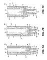
- FIGS. 7A-7C illustrate various configurations of an ignition chamber with a focused thrust design.
- FIG. 8 is a cross-sectional view of yet another alternative embodiment of the present invention, illustrating the ignition chamber being formed as part of a battery cup of the primer.
- the present invention is directed to improvements in the performance of ammunition including small arms ammunition such as shotshells, rimfire/centerfire cartridges, and other rounds, as well as for muzzle loading sabots, and other types of ammunition. Accordingly, while the present invention is illustrated herein in various example embodiments including use in shotshells, it will be understood that the wad of the present invention further can be used with a variety of other types and calibers of ammunition. Accordingly, as shown in FIGS. 2A-2B, 3A-3B and 4-5 , the present invention generally can include a shotshell or similar round of ammunition 10 having a wad 11 or similar structure having an additional inner tube or ignition chamber 12 located in a rearward portion or section 13 of the shotshell or in a firearm chamber 16 ( FIG.
- This ignition tube 12 can be formed in a variety of sizes and configurations such as circular, square, and/or other shapes or configurations, and typically is configured such that it generally is concentric to and is located within a practical separation/distance from the opening of the flash hole 19 of a primer 18 of the shell or round of ammunition 10 . Examples of a first embodiment of the present invention can be seen in FIGS. 2A-2B .
- a shotshell 10 can be provided with an ignition chamber as part of the obturating wad 11 ′ or with an ignition chamber integrally formed with the basewad 11 .
- the ignition chamber or tube portion is shown ( 12 & 12 ′).
- the shotshell typically can include a substantially 1-piece, unitary structure, or can be a multi-piece structure or construction, having a tubular hull or body 20 generally formed from plastic or similar material, that is sealed at a rearward end 13 within a head or base portion 21 , typically made from brass or other metal.
- a primer 18 generally will be received within the head or base 21 , projecting forwardly into the head and the body 20 of the shotshell, and the powder or propellant charge 17 for the shotshell generally will be located forwardly of the primer 18 .
- a gas sealing or obturating wad 11 ′ generally is shown received within the body or case 20 of the shotshell of the present embodiment, positioned in front of the propellant powder 17 and primer 18 , with a chamber 22 being defined forwardly of the wad and in which a payload P, such as a shot pellet payload 23 ( FIG. 2A ) or a slug 24 ( FIG. 2B ) of the shotshell is contained.
- a cupped basewad 11 structure is illustrated in use in the shotshell.
- the gas obturating wad 11 ′ will be integrally formed with the tube or ignition chamber 12 ′ extending rearwardly therefrom.
- This tube or ignition chamber generally defines a chamber 26 ′ in which at least a portion of the powder or propellant of the shotshell can be received.
- the tube or ignition chamber also typically can be aligned along a centerline of the shotshell and will extend for a predetermined distance toward the head 21 of the shotshell 10 .
- the length of the tube can be varied, but typically will extend from the rear 27 ′ of the gas obturating wad 11 ′ to a point terminating approximately in line with the forward end 28 of the primer 18 . As illustrated in FIGS.
- the tube or ignition chamber 12 / 12 ′ further generally will be of a diameter approximately equivalent to a diameter of the primer 18 or otherwise sufficient to substantially receive the exploding primer gases and embers therein.
- the tube or ignition chamber can be between about 0.7-0.2 inches, though greater or lesser size and/or other configuration tubes also can be used.
- a basewad 11 with an integral ignition chamber 12 is formed or molded within the base 21 of the shotshell, including a tube or ignition chamber 12 formed or defined therein and extending upwardly from the basewad 11 along the shotshell from the head or rear end 21 of the base, the ignition chamber 12 defining a chamber 26 and abutting or ending a short distance from the rear surface of a gas obturating wad 31 located adjacent the payload (i.e., the slug 24 ) of the shotshell.
- the primer generally will be contained within the basewad so as to be concentric and integral with the tube or ignition chamber defined by the basewad, and in which at least a portion of the powder is contained.
- the actuation of the primer and initial ignition of the propellant is directed into and along the tube or ignition chamber 26 defined by the basewad 11 , such that the tube or ignition chamber initially contains the primer blast after firing.
- the pressures generated by the ignition of the propellant powder of the shotshell from the primer blast are substantially contained within the tube or ignition chamber at least for an initial time or moment after firing and will create further thrust to drive or accelerate the movement of the gas obturating wad and thus the payload portion of the shotshell out of the case of the shotshell and down-bore along the barrel of the shotgun.
- FIG. 3A illustrates still another embodiment of the shotshell wad 40 with ignition chamber according to the principles of the present invention as applied to a conventional shotshell wad construction, here shown as a Remington Arms Company Inc. Model TGT12S Shotshell Wad, having a body 41 including a lower section of base 42 , and an upper section 43 defining a cup 44 in which a payload such as shot pellets or a slug (not shown) can be received.
- the shotshell wad 40 typically can be received within a shotshell body 20 having a base or head portion 21 in which a primer 18 is received.
- such a conventional shotshell wad 40 can be modified according to the principles of the present invention to include a tube or ignition chamber 46 shown as being integrally formed with the sealing wad base 42 so as to extend rearwardly therefrom.
- the tube generally engages or communicates with the primer 18 of the shotshell, and defines a central chamber 47 or recess in which at least a portion of the propellant powder can be initially ignited by the primer upon firing so as to initially contain and enable further effectiveness of the primer blast.
- the phantom lines 48 shown in FIG. 3A it is also possible, as illustrated by the phantom lines 48 shown in FIG. 3A , to include grooves or cuts formed into the wall 49 of the tube or ignition chamber 46 of the shotshell wad 40 of the present embodiment so as to facilitate a substantially symmetric failure of the tube or ignition chamber 46 at a desired rate.
- Such a generally controlled failure of the tube or ignition chamber will further help expedite the ignition of the remaining propellant powder outside of the tube or ignition chamber.
- the remaining propellant powder outside the tube or ignition chamber can be initiated or ignited more uniformly so as to ensure faster and/or more complete ignition of the entire propellant powder charge within the shotshell, thus further enhancing the acceleration or driving of the payload down-bore and out of the shotshell, as illustrated in FIGS. 6A-6B discussed below.
- FIG. 3B illustrates a further conventional type or style wad 50 such as for a shotshell, modified according to the principles of the present invention.
- the shotshell wad shown in FIG. 3B generally includes an elongated tubular body 51 formed from the series of petals or sections 52 defining a cup 55 and having slits or cuts 53 therebetween to enable the side walls or petals 52 of the wad 50 to flare outwardly after firing.
- the side walls of the wad body 51 terminate at a lower end at a cap or base 54 , which extends rearwardly therefrom and generally includes a recess or cavity 56 formed in its rear surface 57 .
- the shotshell wad 50 further includes an additional tube or ignition chamber 60 formed in the base 54 of the wad 50 , extending rearwardly therefrom and defining a recess or chamber 61 .
- the tube or ignition chamber 60 is generally shown as being substantially centrally located along the base, with the outer edges 62 of the recess or cavity formed in the base of the wad, overlapping or extending thereabout as indicated in FIG. 3B .
- FIGS. 3A and 3B both illustrate the use of a molded tube or ignition chamber integrally formed with the base of the wad, it also is possible to form the tube or ignition chamber separately from the wad, and attach it thereto via adhesives, welding or other attachment means, or to form the tube such as with a basewad as illustrated in FIG. 2A , wherein the tube will engage the rear portion of the wad in a contact or friction fit.
- FIG. 4 illustrates still a further design for a round of ammunition or shell 10 having a basewad 70 and gas sealing or gas obturating wad 71 incorporating the principles of the present invention.
- the gas obturating wad 71 and basewad 70 can be used with a shotshell 10 or similar round of ammunition having a shell body 72 and a base or head 73 , and can be formed so as to couple together, rather than being specifically molded together.
- the gas obturating wad 71 can be formed with a recess or notch 74 that is aligned with the upper end 75 of a tube or ignition chamber 76 formed in the basewad 70 .
- the tube or ignition chamber 76 includes a sidewall 77 that can be formed in cylindrical or other configurations and defines a recess or internal chamber 78 aligned with the primer 18 of the round of ammunition or shotshell. As the gas obturating wad is mounted within the shotshell case, this recess or notch portion 74 can be urged into tight frictional engagement with the upper end 75 of the tube or ignition chamber 76 so as to couple the gas obturating wad 71 to the basewad 70 as indicated in FIG. 4 .
- a better initial seal, indicated at 79 can be created, without having to mold the tube or ignition chamber of the basewad to the gas obturating wad, thus allowing for higher gas pressures upon firing before rupturing or failure of the tube or ignition chamber.
- various other attachment methods or means such as use of adhesives, friction fitting or other, similar attachments also can be used to send and otherwise maintain contact between the wad and basewad.
- FIG. 5 illustrates yet another embodiment of the wad 80 with an ignition chamber according to the principles of the present invention.
- a gas obturating wad 80 is formed with a first or primary tube or ignition chamber 81 , which is shown as generally being centrally aligned or located with respect to a primer 82 of the round of ammunition 10 .
- One or more secondary tubes or chambers 83 further are defined concentrically spaced from and surrounding the primary tube or ignition chamber 81 .
- the secondary tube(s) or chamber(s) 83 define recesses that contain propellant which ignites after the inner tube initial pressurization is relieved by the tube rupture and axial wad movement.
- the second chamber helps further contain the primer/propellant pressurization as needed to enable the desired rate of increase in volume behind the gas obturating wad 80 after firing.
- the proximal or rearward end 87 of the primary ignition chamber 81 can be in engagement with the primer 82 , including engaging the primer in a friction fit, while the forward or distal end 88 of the primary ignition chamber 81 can have a curved or hemispherical configuration to further assist in focusing the pressure waves from the primer blast.
- the tube or ignition chamber 12 / 12 ′ ( FIGS. 2A-2B ), 46 ( FIG. 3A ), 60 ( FIG. 3B ), 76 ( FIG. 4 ), and 81 ( FIG. 5 ) of the wad of each of the embodiments of the present invention acts as a small pressure vessel and helps direct the embers/powder into a confined volume.
- the increased pressure inside the tube or ignition chamber(s) of such wads results in favorable pressure and temperature conditions for powder ignition and is coupled with the tubes ability to confine and direct the particulate emission, allowing for improved initial gas generation.
- the payload i.e.
- shot, slug or other projectile experiences a larger acceleration that results in increased volume behind the payload P as it moves down the bore B of the barrel FB of a firearm, as shown by arrow A in FIG. 6A .
- Such an increase in the volume along the bore B of the barrel FB at a greater rate reduces the peak pressure experienced inside the bore as compared to normal shotshell interior ballistic cycles.
- FIGS. 6A and 6B illustrate the displacement of a payload P/P′ of a round of ammunition being fired utilizing a wad W with the tube or ignition chamber according to the present invention versus a conventional design wad W′.
- FIG. 6A illustrates the down-bore displacement of the payload P fired from a round of ammunition, such as a shotshell, as it proceeds along the barrel of a firearm after firing including the wad with ignition chamber of the present invention
- FIG. 6B illustrates the relative position of the payload P′ fired from a round of ammunition using the conventional wad at the same time “Delta T.”
- This type of system allows for gains in several distinctive areas related to the performance of ammunition, such as a shotshell.
- the first most obvious is a gain in velocity.
- By decreasing the peak pressure experienced in the system more powder can be loaded to restore the loss of pressure and a significant increase in velocity can result.
- This immediately provides opportunities for performance improvements on the steel loads commonly used to hunt waterfowl because of environmental concerns.
- steel loads are at a disadvantage because their density is lower than that of lead, meaning that a pellet of lead identical in size and shape to one of steel going the same velocity will have more energy because its mass will be higher.
- By increasing the speed of the steel load we can restore that missing energy to help compensate for the difference in mass/weight and help bridge the lethality gap between lead and steel shot pellets.
- a second potential gain is in the ability to use faster, cleaner burning powders.
- any one or a combination of the above discussed advantages can be implemented for enhancing the product in specific applications.
- FIGS. 2A-2B and 4-5 show a conceptual view of shotshell with an ignition chamber incorporated into either an obturating wad or a base wad in a shotshell.
- other wad components will be placed between this obturating wad and the payload (shot, buckshot, or slug).
- an advantage of the system of the present invention is that it can be incorporated into any wad system on the market as shown with a modified Remington TGT12S target wad in FIG. 3A , and another variant of a steel shot wad in FIG. 3B .
- the length of the tube can match the height necessary to substantially eliminate any gap between the base wad and beginning of the tube, although some gap can still be provided/used.
- the tube walls could be thickened to increase their ability to withstand pressure of expanding/igniting gases in the ignition chamber for better initial ignition.
- alternate materials that would add strength to the ignition chamber or alternatively provide brittleness to control the consistency of the ignition event further can be used.
- materials to make the ignition chamber such as metals, plastics, cellulose based products, etc., are envisioned as being possible.
- lower cost materials will be seen as providing a better economic choice, such as high and low density polyethylene or similar materials in preferred initial embodiments.
- the wad and/or basewad could also be geometrically designed to couple together by friction as shown in FIG. 4 to create a better initial seal forcing higher pressures before the tube bursts.
- Alternate fastening configurations other than by friction i.e., use of adhesive materials, etc. . . . ) also are possible.
- alternate ignition chamber geometries can be envisioned to provide either equivalent or enhanced ignition.
- a circular cross section other polygonal or star shaped cross sections may be advantageous for reducing the volume further to obtain greater thrust on the base of the wad.
- a substantially continuous curved surface such as shown in FIG. 5 , changing in diameter axially may be advantageous for focusing the primer pressure wave to a specific point.
- a nozzle geometry could be used to optimize thrust.
- FIGS. 7A-7C illustrate embodiments of an ignition chamber with different nozzle geometries.
- Each of FIGS. 7A, 7B, and 7C illustrates a longitudinal cross-section of a respective gas obturating or payload wad 100 a , 100 b , 100 c , each having a respective integrally formed ignition chamber 102 a , 102 b , 102 c extending rearwardly therefrom.
- Each of the wads 100 a , 100 b , 100 c generally includes an elongated tubular body 104 formed from a series of petals or sections 106 defining a cup 108 for at least partially containing a payload (e.g., shot pellets, a slug, etc.).
- a payload e.g., shot pellets, a slug, etc.
- the cup 108 can include slits or cuts 110 extending between the petals 106 to enable the petals 106 to flare outwardly after firing.
- the side walls of the wad body 104 terminate at a lower end at a cap or base 112 , which generally can include a recess or cavity 114 formed therein and extending at least partially about the circumference or periphery of the base. While the bodies 104 of the wads 100 a , 100 b , 100 c , shown in FIGS. 7A-7C , are shown with generally similar features, it will, however, be understood by those skilled in the art that any of these features could be omitted or otherwise configured and/or arranged without departing from the disclosure.
- each of the ignition chambers 102 a , 102 b , 102 c generally includes a respective proximal end 116 a , 116 b , 116 c that can be aligned with and positioned adjacent a forward end of a primer of a firearm cartridge or shell (not shown), and a respective distal end 118 a , 118 b , 118 c that is proximate the base 112 of its respective wad 100 a , 100 b , 100 c .
- Each of the ignition chambers 102 a , 102 b , 102 c further includes an ignition tube 120 a , 120 b , 120 c that can be integrally formed with or affixed to the base 112 of its payload wad, generally projecting rearwardly therefrom.
- the ignition tube 120 a defines an ignition recess 122 a that is open at the proximal end 116 a for receiving a primer blast from the primer (not shown).
- the ignition recess 122 a is shown in this embodiment as being widest (e.g., has a maximum cross-sectional area) at its proximal end 116 a and generally is narrower (e.g., has a reduced or minimum cross-sectional area) at its distal end 118 a .
- the nozzle geometry of the ignition chamber 102 a further is defined by an angled or tapering interior surface 124 a formed along the ignition tube 120 a .
- This interior surface 124 a can include a first portion 126 a that extends from the distal end 118 a of the ignition chamber 102 a and can have a generally wedge or conical shape as shown in the longitudinal cross-section of FIG. 7A .
- the first portion 126 a of the interior surface 124 a gradually widens or expands at a first angle from the distal end 118 a toward the proximal end 116 a .
- a second portion 128 a of the interior surface extends at a second angle from the first portion 126 a to the proximal end 116 a of the ignition chamber. Accordingly, the ignition recess 122 a gradually widens in a dual angle configuration from the narrowest portion at the distal end 118 a to the widest portion at the proximal end 116 a.
- the first and second angles of the first portion 126 a and second portion 128 a can be different.
- the first angle of the first portion 126 a is shown in FIG. 7A as being larger than the second angle of the second portion 128 a .
- the second angle can be larger than or substantially the same as the first angle.
- the ignition tube 120 a also can have a generally circular transverse cross-section so that the ignition recess 122 a is generally cone-shaped.
- the ignition tube 120 a can have any suitable cross-sectional shape.
- the ignition tube 120 b can define an ignition recess 122 b that is generally similar to the ignition recess 122 a of FIG. 7A , except while the first and second portions 126 a , 128 a of the interior surface 124 a are about the same length, the first potion 126 b of the interior surface 124 b of the ignition recess 122 b is shown in this embodiment as being somewhat longer than the second portion 128 b .
- the second portion of the interior surface of an ignition recess can be longer than the first portion.
- the ignition recess can widen from the distal end to the proximal end at a consistent slope (e.g., a single angle configuration), or the interior surface can include more than two portions having different angles (e.g., the multiple portions can have increasing angles or decreasing angles as the ignition recess widens, the multiple portions can have alternating angles, etc.).
- the ignition tube 120 b can define an ignition recess 122 c having a shaped—i.e., conical or substantially curved interior surface 124 c so that the longitudinal cross-section of the ignition recess 122 c generally forms a parabola or other shaped/focused surface at its distal end 118 c .
- the ignition recess can be alternatively shaped, arranged, configured, and/or disposed without departing from the disclosure.
- the wad 100 a can be incorporated into a shotshell or another type of ammunition so that the proximal end 116 a of the ignition chamber 102 a of the wad generally is aligned with and adjacent a forward end of a primer of an ammunition shell or cartridge.
- a propellant (not shown) can be contained in the ignition recess 122 a and in the base of the shell or cartridge exterior to the ignition tube 120 a .
- the primer blast can exit the forward end of the primer and will be received in the ignition chamber 102 a .
- the primer blast will ignite the propellant in the ignition chamber 102 a
- the shape of the ignition recess 122 a can help focus and contain the primer blast in the ignition chamber, including reducing or compressing the volume of the primer blast, which can foster faster ignition and ignition of more of the propellant within the ignition chamber, and resultingly provide an enhanced initial pressure in the ignition chamber prior to and/or during the ignition of the propellant to the exterior of the ignition chamber.
- the propellant in the ignition chamber also can be different from the propellant exterior to the ignition chamber.
- one propellant can be a fast-burning propellant that burns more quickly (producing higher initial pressure) and generally burns more completely
- the other propellant can be a relatively slow-burning propellant that may help avoid exceeding pressure tolerances in a chamber of a firearm.
- the faster burning propellant can be used within the ignition chamber, or outside the ignition chamber, with the slower burning propellant used in the ignition chamber, as needed depending upon the desired burning and performance characteristics of the shotshell or cartridge.
- the ignition chambers 102 b , 102 c can operate in a similar fashion as the ignition chamber 102 a to provide different focusing of the primer blast in the ignition chamber.
- FIG. 8 illustrates a longitudinal cross-section of a further alternative embodiment of a round of ammunition 200 (e.g. a shotshell) having a shell body 202 , a base 204 , and a gas obturating or payload wad 206 .
- a primer cup 210 having a battery cup 212 is received with the base 204 of the round/shell 200 .
- a paper foil 215 is assembled forward of an anvil 217 in the primer cup 210 .
- the forward end 213 of the battery cup further generally can be extended with an elongated ignition chamber 214 .
- the payload wad 206 can be alternatively configured without departing from the disclosure.
- a rearward end of the shell body 202 is disposed in the base (brass) 204 with the primer cup 210 and the battery cup 212 mounted within the base 204 and extending forwardly from the rearward end of the base 204 .
- the primer cup 210 also can generally include a primer, the paper foil 215 , and the anvil 217 , as well as other features, which can be received in the extended battery cup 212 with the ignition chamber 214 .
- the ignition chamber 214 comprises an ignition tube 216 that can be integrally formed with the battery cup 212 , or mounted thereto so that a proximal end 218 of the ignition chamber 214 is aligned with and extends/projects from the forward end 213 of the primer cup 210 adjacent the battery cup 212 .
- the ignition tube 216 can extend from the battery cup 212 toward the payload wad 206 and, in one embodiment, a distal end 220 of the ignition chamber 214 can abut a rearward surface 222 of the base of the payload wad 206 .
- a first propellant 224 generally can be contained in the ignition tube 216 and a second propellant 226 can be contained in the shell body 202 between the base wad 208 and the payload wad 206 along the exterior of the ignition tube 216 .
- the first propellant 224 and the second propellant 226 can include the same propellant material, or, alternatively, can be different propellant materials.
- the first propellant 224 can be a slower-burning propellant
- the second propellant 226 can be a relatively faster-burning propellant
- the first propellant can be a faster-burning propellant with the second propellant comprising the slower-burning propellant.
- the propellant can be otherwise configured and/or arranged without departing from the disclosure.
- Exemplary slower burning propellants can include the St. Marks 500 series of powders (e.g., the St. Marks 502 or 504 powders) manufactured by General Dynamics, or the AMS-10, AMS-20, or AMS-30 powders manufactured by Alliant Techsystems Inc.
- Faster burning propellants can include St. Marks 474 powder manufactured by General Dynamics or other powders with speeds between those of the Alliant 375 to AMS-40 powders manufactured by Alliant Techsystems Inc., for example.
- These propellants are included by way of example only. Any suitable propellants can be used inside and outside the ignition chamber without departing from the scope of the disclosure.
- the ignition chambers of the various embodiments can be incorporated into any suitable style or configuration of ammunition.
- the wad and shell body styles and configurations described above are included by way of example.
- the ignition chambers of the various embodiments could be formed separately to be affixed to a payload wad, a base wad, or a battery cup, or to be otherwise disposed in a round of ammunition.
- the primer battery cup could be extended to accomplish the same goal.
- the primer battery cup could be configured similar to an open ended flash tube and function similarly to the embodiment shown in FIG. 2A .
- a normal basewad could house a long version of a shotshell primer to provide a substantially equivalent configuration.
Abstract
Description
Claims (12)
Priority Applications (1)
| Application Number | Priority Date | Filing Date | Title |
|---|---|---|---|
| US14/455,673 US9500453B2 (en) | 2008-10-27 | 2014-08-08 | Wad with ignition chamber |
Applications Claiming Priority (5)
| Application Number | Priority Date | Filing Date | Title |
|---|---|---|---|
| US10867808P | 2008-10-27 | 2008-10-27 | |
| US11328608P | 2008-11-11 | 2008-11-11 | |
| US12/606,447 US8220393B2 (en) | 2008-10-27 | 2009-10-27 | Wad with ignition chamber |
| US13/548,464 US8800449B2 (en) | 2008-10-27 | 2012-07-13 | Wad with ignition chamber |
| US14/455,673 US9500453B2 (en) | 2008-10-27 | 2014-08-08 | Wad with ignition chamber |
Related Parent Applications (1)
| Application Number | Title | Priority Date | Filing Date |
|---|---|---|---|
| US13/548,464 Continuation US8800449B2 (en) | 2008-10-27 | 2012-07-13 | Wad with ignition chamber |
Publications (2)
| Publication Number | Publication Date |
|---|---|
| US20140345488A1 US20140345488A1 (en) | 2014-11-27 |
| US9500453B2 true US9500453B2 (en) | 2016-11-22 |
Family
ID=48803626
Family Applications (2)
| Application Number | Title | Priority Date | Filing Date |
|---|---|---|---|
| US13/548,464 Active 2030-01-06 US8800449B2 (en) | 2008-10-27 | 2012-07-13 | Wad with ignition chamber |
| US14/455,673 Active 2029-11-15 US9500453B2 (en) | 2008-10-27 | 2014-08-08 | Wad with ignition chamber |
Family Applications Before (1)
| Application Number | Title | Priority Date | Filing Date |
|---|---|---|---|
| US13/548,464 Active 2030-01-06 US8800449B2 (en) | 2008-10-27 | 2012-07-13 | Wad with ignition chamber |
Country Status (6)
| Country | Link |
|---|---|
| US (2) | US8800449B2 (en) |
| EP (1) | EP2872852A1 (en) |
| AU (1) | AU2013288690A1 (en) |
| CA (1) | CA2878589A1 (en) |
| MX (1) | MX2015000512A (en) |
| WO (1) | WO2014011628A1 (en) |
Cited By (74)
| Publication number | Priority date | Publication date | Assignee | Title |
|---|---|---|---|---|
| US10041777B1 (en) | 2016-03-09 | 2018-08-07 | True Velocity, Inc. | Three-piece primer insert having an internal diffuser for polymer ammunition |
| US10234249B2 (en) | 2010-11-10 | 2019-03-19 | True Velocity Ip Holdings, Llc | Polymer ammunition having a primer insert with a primer pocket groove |
| US10365074B2 (en) | 2017-11-09 | 2019-07-30 | True Velocity Ip Holdings, Llc | Multi-piece polymer ammunition cartridge |
| US10408592B2 (en) | 2010-11-10 | 2019-09-10 | True Velocity Ip Holdings, Llc | One piece polymer ammunition cartridge having a primer insert and methods of making the same |
| US10466022B2 (en) | 2016-03-25 | 2019-11-05 | Vista Outdoor Operations Llc | Reduced energy MSR system |
| US10612896B2 (en) | 2010-11-10 | 2020-04-07 | True Velocity Ip Holdings, Llc | Method of making a metal injection molded ammunition cartridge |
| USD881326S1 (en) | 2018-04-20 | 2020-04-14 | True Velocity Ip Holdings, Llc | Ammunition cartridge |
| USD881328S1 (en) | 2018-04-20 | 2020-04-14 | True Velocity Ip Holdings, Llc | Ammunition cartridge |
| USD881327S1 (en) | 2018-04-20 | 2020-04-14 | True Velocity Ip Holdings, Llc | Ammunition cartridge |
| USD881324S1 (en) | 2018-04-20 | 2020-04-14 | True Velocity Ip Holdings, Llc | Ammunition cartridge |
| USD881323S1 (en) | 2018-04-20 | 2020-04-14 | True Velocity Ip Holdings, Llc | Ammunition cartridge |
| USD881325S1 (en) | 2018-04-20 | 2020-04-14 | True Velocity Ip Holdings, Llc | Ammunition cartridge |
| USD882028S1 (en) | 2018-04-20 | 2020-04-21 | True Velocity Ip Holdings, Llc | Ammunition cartridge |
| USD882033S1 (en) | 2018-04-20 | 2020-04-21 | True Velocity Ip Holdings, Llc | Ammunition cartridge |
| USD882024S1 (en) | 2018-04-20 | 2020-04-21 | True Velocity Ip Holdings, Llc | Ammunition cartridge |
| USD882027S1 (en) | 2018-04-20 | 2020-04-21 | True Velocity Ip Holdings, Llc | Ammunition cartridge |
| USD882031S1 (en) | 2018-04-20 | 2020-04-21 | True Velocity Ip Holdings, Llc | Ammunition cartridge |
| USD882020S1 (en) | 2018-04-20 | 2020-04-21 | True Velocity Ip Holdings, Llc | Ammunition cartridge |
| USD882026S1 (en) | 2018-04-20 | 2020-04-21 | True Velocity Ip Holdings, Llc | Ammunition cartridge |
| USD882030S1 (en) | 2018-04-20 | 2020-04-21 | True Velocity Ip Holdings, Llc | Ammunition cartridge |
| USD882023S1 (en) | 2018-04-20 | 2020-04-21 | True Velocity Ip Holdings, Llc | Ammunition cartridge |
| USD882021S1 (en) | 2018-04-20 | 2020-04-21 | True Velocity Ip Holdings, Llc | Ammunition cartridge |
| USD882032S1 (en) | 2018-04-20 | 2020-04-21 | True Velocity Ip Holdings, Llc | Ammunition cartridge |
| USD882022S1 (en) | 2018-04-20 | 2020-04-21 | True Velocity Ip Holdings, Llc | Ammunition cartridge |
| USD882025S1 (en) | 2018-04-20 | 2020-04-21 | True Velocity Ip Holdings, Llc | Ammunition cartridge |
| USD882029S1 (en) | 2018-04-20 | 2020-04-21 | True Velocity Ip Holdings, Llc | Ammunition cartridge |
| USD882019S1 (en) | 2018-04-20 | 2020-04-21 | True Velocity Ip Holdings, Llc | Ammunition cartridge |
| USD882724S1 (en) | 2018-04-20 | 2020-04-28 | True Velocity Ip Holdings, Llc | Ammunition cartridge |
| USD882722S1 (en) | 2018-04-20 | 2020-04-28 | True Velocity Ip Holdings, Llc | Ammunition cartridge |
| USD882723S1 (en) | 2018-04-20 | 2020-04-28 | True Velocity Ip Holdings, Llc | Ammunition cartridge |
| USD882721S1 (en) | 2018-04-20 | 2020-04-28 | True Velocity Ip Holdings, Llc | Ammunition cartridge |
| USD882720S1 (en) | 2018-04-20 | 2020-04-28 | True Velocity Ip Holdings, Llc | Ammunition cartridge |
| USD884115S1 (en) | 2018-04-20 | 2020-05-12 | True Velocity Ip Holdings, Llc | Ammunition cartridge |
| USD886231S1 (en) | 2017-12-19 | 2020-06-02 | True Velocity Ip Holdings, Llc | Ammunition cartridge |
| USD886937S1 (en) | 2017-12-19 | 2020-06-09 | True Velocity Ip Holdings, Llc | Ammunition cartridge |
| US10704872B1 (en) | 2019-02-14 | 2020-07-07 | True Velocity Ip Holdings, Llc | Polymer ammunition and cartridge having a convex primer insert |
| US10704879B1 (en) | 2019-02-14 | 2020-07-07 | True Velocity Ip Holdings, Llc | Polymer ammunition and cartridge having a convex primer insert |
| US10704880B1 (en) | 2019-02-14 | 2020-07-07 | True Velocity Ip Holdings, Llc | Polymer ammunition and cartridge having a convex primer insert |
| US10704877B2 (en) | 2010-11-10 | 2020-07-07 | True Velocity Ip Holdings, Llc | One piece polymer ammunition cartridge having a primer insert and methods of making the same |
| US10704876B2 (en) | 2010-11-10 | 2020-07-07 | True Velocity Ip Holdings, Llc | One piece polymer ammunition cartridge having a primer insert and methods of making the same |
| USD891569S1 (en) | 2019-03-12 | 2020-07-28 | True Velocity Ip Holdings, Llc | Ammunition cartridge nose having an angled shoulder |
| USD891570S1 (en) | 2019-03-12 | 2020-07-28 | True Velocity Ip Holdings, Llc | Ammunition cartridge nose |
| USD891567S1 (en) | 2019-03-12 | 2020-07-28 | True Velocity Ip Holdings, Llc | Ammunition cartridge nose having an angled shoulder |
| USD891568S1 (en) | 2019-03-12 | 2020-07-28 | True Velocity Ip Holdings, Llc | Ammunition cartridge nose having an angled shoulder |
| US10731957B1 (en) | 2019-02-14 | 2020-08-04 | True Velocity Ip Holdings, Llc | Polymer ammunition and cartridge having a convex primer insert |
| USD892258S1 (en) | 2019-03-12 | 2020-08-04 | True Velocity Ip Holdings, Llc | Ammunition cartridge nose having an angled shoulder |
| USD893666S1 (en) | 2019-03-11 | 2020-08-18 | True Velocity Ip Holdings, Llc | Ammunition cartridge nose having an angled shoulder |
| USD893668S1 (en) | 2019-03-11 | 2020-08-18 | True Velocity Ip Holdings, Llc | Ammunition cartridge nose having an angled shoulder |
| USD893667S1 (en) | 2019-03-11 | 2020-08-18 | True Velocity Ip Holdings, Llc | Ammunition cartridge nose having an angled shoulder |
| USD893665S1 (en) | 2019-03-11 | 2020-08-18 | True Velocity Ip Holdings, Llc | Ammunition cartridge nose having an angled shoulder |
| USD894320S1 (en) | 2019-03-21 | 2020-08-25 | True Velocity Ip Holdings, Llc | Ammunition Cartridge |
| USD903038S1 (en) | 2018-04-20 | 2020-11-24 | True Velocity Ip Holdings, Llc | Ammunition cartridge |
| USD903039S1 (en) | 2018-04-20 | 2020-11-24 | True Velocity Ip Holdings, Llc | Ammunition cartridge |
| US10900760B2 (en) | 2010-11-10 | 2021-01-26 | True Velocity Ip Holdings, Llc | Method of making a polymer ammunition cartridge |
| US10914558B2 (en) | 2010-11-10 | 2021-02-09 | True Velocity Ip Holdings, Llc | Subsonic polymeric ammunition with diffuser |
| US10921106B2 (en) | 2019-02-14 | 2021-02-16 | True Velocity Ip Holdings, Llc | Polymer ammunition and cartridge having a convex primer insert |
| USD913403S1 (en) | 2018-04-20 | 2021-03-16 | True Velocity Ip Holdings, Llc | Ammunition cartridge |
| US11047663B1 (en) | 2010-11-10 | 2021-06-29 | True Velocity Ip Holdings, Llc | Method of coding polymer ammunition cartridges |
| US11047664B2 (en) | 2010-11-10 | 2021-06-29 | True Velocity Ip Holdings, Llc | Lightweight polymer ammunition cartridge casings |
| US11118851B2 (en) | 2016-03-25 | 2021-09-14 | Vista Outdoor Operations Llc | Reduced energy MSR system |
| US11118882B2 (en) | 2010-11-10 | 2021-09-14 | True Velocity Ip Holdings, Llc | Method of making a polymeric subsonic ammunition cartridge |
| US11209252B2 (en) | 2010-11-10 | 2021-12-28 | True Velocity Ip Holdings, Llc | Subsonic polymeric ammunition with diffuser |
| US11215430B2 (en) | 2010-11-10 | 2022-01-04 | True Velocity Ip Holdings, Llc | One piece polymer ammunition cartridge having a primer insert and methods of making the same |
| US11231257B2 (en) | 2010-11-10 | 2022-01-25 | True Velocity Ip Holdings, Llc | Method of making a metal injection molded ammunition cartridge |
| US11248885B2 (en) | 2010-11-10 | 2022-02-15 | True Velocity Ip Holdings, Llc | Subsonic polymeric ammunition cartridge |
| US11293732B2 (en) | 2010-11-10 | 2022-04-05 | True Velocity Ip Holdings, Llc | Method of making polymeric subsonic ammunition |
| US11300393B2 (en) | 2010-11-10 | 2022-04-12 | True Velocity Ip Holdings, Llc | Polymer ammunition having a MIM primer insert |
| US11313654B2 (en) | 2010-11-10 | 2022-04-26 | True Velocity Ip Holdings, Llc | Polymer ammunition having a projectile made by metal injection molding |
| US11340053B2 (en) | 2019-03-19 | 2022-05-24 | True Velocity Ip Holdings, Llc | Methods and devices metering and compacting explosive powders |
| US11435171B2 (en) | 2018-02-14 | 2022-09-06 | True Velocity Ip Holdings, Llc | Device and method of determining the force required to remove a projectile from an ammunition cartridge |
| US11448488B2 (en) | 2017-08-08 | 2022-09-20 | True Velocity Ip Holdings, Llc | Metal injection molded ammunition cartridge |
| US11543218B2 (en) | 2019-07-16 | 2023-01-03 | True Velocity Ip Holdings, Llc | Polymer ammunition having an alignment aid, cartridge and method of making the same |
| US11614314B2 (en) | 2018-07-06 | 2023-03-28 | True Velocity Ip Holdings, Llc | Three-piece primer insert for polymer ammunition |
| US11733015B2 (en) | 2018-07-06 | 2023-08-22 | True Velocity Ip Holdings, Llc | Multi-piece primer insert for polymer ammunition |
Families Citing this family (23)
| Publication number | Priority date | Publication date | Assignee | Title |
|---|---|---|---|---|
| US8800449B2 (en) * | 2008-10-27 | 2014-08-12 | Ra Brands, L.L.C. | Wad with ignition chamber |
| US10429156B2 (en) | 2010-11-10 | 2019-10-01 | True Velocity Ip Holdings, Llc | Subsonic polymeric ammunition cartridge |
| US10081057B2 (en) | 2010-11-10 | 2018-09-25 | True Velocity, Inc. | Method of making a projectile by metal injection molding |
| US10048052B2 (en) | 2010-11-10 | 2018-08-14 | True Velocity, Inc. | Method of making a polymeric subsonic ammunition cartridge |
| US10048049B2 (en) | 2010-11-10 | 2018-08-14 | True Velocity, Inc. | Lightweight polymer ammunition cartridge having a primer diffuser |
| US11118875B1 (en) | 2010-11-10 | 2021-09-14 | True Velocity Ip Holdings, Llc | Color coded polymer ammunition cartridge |
| US10190857B2 (en) | 2010-11-10 | 2019-01-29 | True Velocity Ip Holdings, Llc | Method of making polymeric subsonic ammunition |
| US10591260B2 (en) | 2010-11-10 | 2020-03-17 | True Velocity Ip Holdings, Llc | Polymer ammunition having a projectile made by metal injection molding |
| USD861118S1 (en) | 2011-11-09 | 2019-09-24 | True Velocity Ip Holdings, Llc | Primer insert |
| USD780283S1 (en) * | 2015-06-05 | 2017-02-28 | True Velocity, Inc. | Primer diverter cup used in polymer ammunition |
| US9587918B1 (en) | 2015-09-24 | 2017-03-07 | True Velocity, Inc. | Ammunition having a projectile made by metal injection molding |
| US9879957B2 (en) | 2015-10-15 | 2018-01-30 | Vista Outdoor Operations Llc | Shotshell having wad with enhanced fin deployment |
| US10422611B1 (en) | 2015-10-15 | 2019-09-24 | Vista Outdoor Operations Llc | Shotshell having wad with enhanced fin deployment |
| USD809622S1 (en) | 2016-01-28 | 2018-02-06 | Vista Outdoor Operations Llc | Shotgun wad |
| USD810226S1 (en) | 2016-02-04 | 2018-02-13 | Vista Outdoor Operations Llc | Shotgun wad |
| US9551557B1 (en) | 2016-03-09 | 2017-01-24 | True Velocity, Inc. | Polymer ammunition having a two-piece primer insert |
| US9518810B1 (en) | 2016-03-09 | 2016-12-13 | True Velocity, Inc. | Polymer ammunition cartridge having a two-piece primer insert |
| US9523563B1 (en) | 2016-03-09 | 2016-12-20 | True Velocity, Inc. | Method of making ammunition having a two-piece primer insert |
| US9506735B1 (en) | 2016-03-09 | 2016-11-29 | True Velocity, Inc. | Method of making polymer ammunition cartridges having a two-piece primer insert |
| USD1017756S1 (en) | 2018-02-23 | 2024-03-12 | Federal Cartridge Company | Shotgun wad |
| US10976144B1 (en) | 2018-03-05 | 2021-04-13 | Vista Outdoor Operations Llc | High pressure rifle cartridge with primer |
| USD903812S1 (en) * | 2018-11-15 | 2020-12-01 | Security Devices International Inc. | Wad for a shotgun shell |
| IT202000025438A1 (en) * | 2020-10-27 | 2022-04-27 | Fiocchi Munizioni Spa | BORAGE SYSTEM |
Citations (122)
| Publication number | Priority date | Publication date | Assignee | Title |
|---|---|---|---|---|
| US219840A (en) | 1879-09-23 | Improvement in methods of manufacturing bullets | ||
| US419220A (en) | 1890-01-14 | Speghtjgaiioh | ||
| US681091A (en) | 1901-04-11 | 1901-08-20 | Charles Ellsworth Adamson | Wad for cartridges. |
| US1659649A (en) | 1923-07-30 | 1928-02-21 | Western Cartridge Co | Wad for shot shells |
| US1771897A (en) | 1925-11-21 | 1930-07-29 | Western Cartridge Co | Cartridge wad and process of making the same |
| US1872107A (en) | 1927-01-09 | 1932-08-16 | Bond Mfg Corp | Gun wad |
| US1908314A (en) | 1930-12-11 | 1933-05-09 | Ici Ltd | Shotgun cartridge wad |
| US2476291A (en) | 1945-05-31 | 1949-07-19 | Thomas H Garber | Sealing wad |
| US2665635A (en) | 1949-06-30 | 1954-01-12 | Fr Des Munitions De Chasse De | Wad |
| US2788744A (en) | 1953-04-27 | 1957-04-16 | Soltam Ltd | Projectile for mortar |
| DE1808779U (en) | 1959-12-18 | 1960-03-31 | Alois Heine | ELECTRIC LUMINAIRE, PRESENTLY FOR ROOM LIGHTING FOR TELEVISION RECEPTION. |
| US2953816A (en) | 1955-08-31 | 1960-09-27 | Remington Arms Co Inc | Shot shell wad molding process |
| US2973711A (en) | 1959-02-04 | 1961-03-07 | Alcan Company Inc | Base wad overlay |
| FR1255993A (en) | 1960-02-01 | 1961-03-17 | Improvements to firearm cartridges | |
| US2986998A (en) | 1958-12-04 | 1961-06-06 | Alcan Company Inc | Obturating wad |
| US3022734A (en) | 1959-07-27 | 1962-02-27 | Remington Arms Co Inc | Shot shell wad |
| US3022731A (en) | 1959-05-12 | 1962-02-27 | Olin Mathieson | Shotshell wad structure |
| FR78417E (en) | 1960-02-01 | 1962-07-20 | Improvements to firearm cartridges | |
| US3053185A (en) | 1959-12-03 | 1962-09-11 | Phillips Petroleum Co | Expandable wads for shotgun shells |
| US3058420A (en) | 1960-04-26 | 1962-10-16 | Canadian Ind | Slug-loaded shotgun cartridge |
| US3095817A (en) | 1960-07-25 | 1963-07-02 | Alcan Company Inc | Wad column |
| US3120807A (en) | 1963-04-11 | 1964-02-11 | James E Lyon | Filler wad for shotgun shells |
| US3138102A (en) | 1962-11-13 | 1964-06-23 | Earl J Meyer | Shotgun projectile having slits |
| US3180265A (en) | 1963-03-01 | 1965-04-27 | R & K Plastic Ind Co | Shot shell wad and container |
| US3191534A (en) | 1962-01-20 | 1965-06-29 | Vecchiotti Ado | Adjustable wad device for hunting and shooting cartridges |
| US3211100A (en) | 1961-03-13 | 1965-10-12 | Alcan Company Inc | Wad column |
| US3215076A (en) | 1963-09-03 | 1965-11-02 | Remington Arms Co Inc | Shotshell |
| US3217648A (en) | 1962-10-08 | 1965-11-16 | Remington Arms Co Inc | Combination wad column and shot liner |
| US3221658A (en) | 1963-09-24 | 1965-12-07 | Devaux Raymond Henri Pierre | Shot-gun cartridge and wad therefor |
| US3234877A (en) | 1964-04-27 | 1966-02-15 | Herter Inc S | Shotgun shell wad with powder pocket |
| US3262392A (en) | 1964-04-06 | 1966-07-26 | Clarence J Becker | Shot shell wad |
| US3266421A (en) | 1962-06-25 | 1966-08-16 | Ronald W Comerford | Pouch-wad |
| US3279375A (en) | 1964-04-27 | 1966-10-18 | Herter Inc S | Shotgun shell wad |
| US3280745A (en) | 1964-05-22 | 1966-10-25 | Mattarelli Ennio | Cork filled plastic bag wad for shot gun shell |
| US3285174A (en) | 1965-05-28 | 1966-11-15 | Olin Mathieson | Wad and shot protector device |
| US3289586A (en) | 1964-11-09 | 1966-12-06 | Fed Cartridge Corp | Wad column |
| US3298313A (en) | 1964-04-06 | 1967-01-17 | Ronald W Comerford | Wad column device |
| US3299813A (en) | 1964-12-17 | 1967-01-24 | Remington Arms Co Inc | Water sealing shot container for shotshells |
| US3323456A (en) | 1965-08-09 | 1967-06-06 | Rothman Barry | Cartridge having flash and noise projectile |
| FR1534004A (en) | 1967-06-14 | 1968-07-26 | Subcaliber projectile, composite, stabilized by rotation | |
| US3402664A (en) | 1966-09-13 | 1968-09-24 | John E. Cramer | Shot holder and wad for shot shells |
| US3420178A (en) | 1967-03-09 | 1969-01-07 | Henry George Rempel | Wad for shotgun shells |
| US3422762A (en) | 1967-06-19 | 1969-01-21 | Alcan Co Inc | Unitary wad column and shot container |
| US3427920A (en) | 1967-06-19 | 1969-02-18 | Alcan Co Inc | Base wad |
| US3469527A (en) | 1968-03-07 | 1969-09-30 | Leland A Pace | Shotgun wad |
| US3503332A (en) | 1967-02-27 | 1970-03-31 | Misitano Ag Dr Ing | Wad |
| US3507221A (en) | 1966-07-21 | 1970-04-21 | Brevets Aero Mecaniques | Armor piercing,sabot shells |
| US3507220A (en) * | 1969-01-02 | 1970-04-21 | Clifton M Mcclure | Ammunition round |
| US3565010A (en) | 1968-06-10 | 1971-02-23 | Remington Arms Co Inc | Plastic wad column |
| US3598054A (en) | 1969-02-24 | 1971-08-10 | Avco Corp | Recoil attenuating munition |
| US3653326A (en) | 1969-02-12 | 1972-04-04 | Peter John Howsam | Wads for cartridges |
| US3662683A (en) | 1970-11-04 | 1972-05-16 | Federal Cartridge Corp | Shotgun shell wad |
| US3670650A (en) | 1970-06-10 | 1972-06-20 | Canadian Ind | Shotshell wad |
| US3707915A (en) | 1970-10-19 | 1973-01-02 | J Kerzman | Wad assembly for shotgun shell |
| US3720171A (en) | 1971-03-12 | 1973-03-13 | Olin Corp | Plastic shot shell wad |
| US3721197A (en) | 1970-12-04 | 1973-03-20 | Olin Corp | Injection-expansion molded shotshell wad and method of forming the same |
| US3722420A (en) | 1970-11-04 | 1973-03-27 | Herter Inc S | Tapered cup wad |
| US3727557A (en) | 1971-10-21 | 1973-04-17 | S Starcevich | Wad for shotgun shells |
| US3750579A (en) | 1971-09-09 | 1973-08-07 | L Bellington | Shotgun shell wad |
| US3750580A (en) | 1970-11-13 | 1973-08-07 | Asahi Chemical Ind | Wads for charging shot of shot gun |
| US3788224A (en) | 1966-06-24 | 1974-01-29 | Federal Cartridge Corp | Nested wad column and method of shot shell loading |
| US3804019A (en) | 1972-10-04 | 1974-04-16 | Hercules Inc | Shot shell and improved wadding therefor |
| US3812784A (en) | 1972-01-17 | 1974-05-28 | Herter Inc S | One piece wad column and shot cup |
| US3835783A (en) | 1972-12-04 | 1974-09-17 | Remington Arms Co Inc | Shot container wad for hard shot |
| US3974775A (en) | 1974-11-04 | 1976-08-17 | Kerzman Jack A | Wad unit for shotgun shell |
| US3978794A (en) | 1973-12-28 | 1976-09-07 | Giulio Fiocchi, S.P.A. | Base wad for shotshells |
| US4004522A (en) | 1974-09-26 | 1977-01-25 | Unit Wad Limited | Shot shell wadding |
| FR2343218A1 (en) | 1976-03-03 | 1977-09-30 | Bourlange Jean Georges | Bullet for hunting rifle - has reduced section and weight and is held in tulip:shaped wad held closed by sliding ring |
| US4103621A (en) | 1976-07-19 | 1978-08-01 | Fackler David G | Wad column for shotshells |
| US4151799A (en) | 1977-09-23 | 1979-05-01 | Jackson John W | Wad for shotgun shell |
| US4164903A (en) | 1977-09-08 | 1979-08-21 | Bouza Gordon F | Shotgun wad for use as a practice projectile |
| US4220090A (en) | 1978-09-05 | 1980-09-02 | Fackler David G | Shot wad column |
| US4291625A (en) | 1979-03-02 | 1981-09-29 | Stagg Jr George A | Shot gun shell construction |
| US4295426A (en) | 1978-03-22 | 1981-10-20 | Snia Viscosa Societa Nazionale Industria Applicazioni Viscosa S.P.A. | Plastic wads and wad assemblies for shot cartridges |
| US4307664A (en) | 1979-11-23 | 1981-12-29 | Merle Norman Cosmetics | Plastic shot shell wad |
| US4452144A (en) | 1980-04-15 | 1984-06-05 | Nagatoshi Maki | Shotgun cartridge and wad thereof |
| US4553481A (en) | 1984-04-11 | 1985-11-19 | Vero Ricci | Shot gun shell tracer wad |
| FR2568001A1 (en) | 1984-07-18 | 1986-01-24 | Baschieri Pellagri Spa | CARTRIDGE FOR HUNTING RIFLES |
| US4574701A (en) | 1982-10-12 | 1986-03-11 | Fiocchi Munizioni Spa | Wad for cartridges of hunting and shooting arms |
| US4587905A (en) | 1980-07-18 | 1986-05-13 | Nagatoshi Maki | Wad and slug for a shotgun cartridge |
| US4627356A (en) | 1985-06-11 | 1986-12-09 | Louis Buczkowski | Two-piece booster shot shell wad |
| US4669385A (en) | 1983-09-28 | 1987-06-02 | Nagatoshi Maki | Wad for shotgun shotshell |
| US4676170A (en) | 1984-07-16 | 1987-06-30 | Non-Toxic Components, Inc. | One-piece wad structure adapted for reloading of hard shot |
| US4733613A (en) | 1986-06-27 | 1988-03-29 | Olin Corporation | Adjustable volume shot wad structure and method of assembling the same |
| US4773329A (en) | 1985-11-25 | 1988-09-27 | Olin Corporation | Composite shot wad structure for steel and other hard shot |
| US4776279A (en) | 1987-09-17 | 1988-10-11 | Pejsa Arthur J | Expanding ballistic projectile |
| US4782759A (en) | 1987-06-30 | 1988-11-08 | Hawk Walter J | Dual sealed composite wad structure |
| US4815388A (en) | 1986-11-11 | 1989-03-28 | Olin Corporation | Shot charge and wad structure for a combat shotgun |
| US4860661A (en) | 1987-11-06 | 1989-08-29 | Diehl Gmbh & Co. | Saboted projectile with propellant cage |
| US4970959A (en) | 1989-08-15 | 1990-11-20 | Olin Corporation | Collapsible basewad |
| USD314806S (en) | 1986-09-08 | 1991-02-19 | Remington Arms Company | Shotgun cartridge wad or similar article |
| US5105713A (en) | 1991-03-11 | 1992-04-21 | The United States Of America As Represented By The Secretary Of The Army | Electromagnetically accelerated projectile |
| US5171934A (en) | 1990-12-24 | 1992-12-15 | Larry Moore | Shortened shotshell with double-cupped wadding |
| US5214238A (en) | 1992-03-23 | 1993-05-25 | Christopher Young | Sabot for chambering conventional bullets in a shotgun |
| FR2687217A1 (en) | 1992-02-11 | 1993-08-13 | Fn Engineerung Sa | Multiple ammunition and weapon for making use of such ammunition |
| US5235915A (en) | 1992-05-26 | 1993-08-17 | Stevens Robert D | Shotgun slug tracer round and improved shotgun slug |
| US5239928A (en) | 1992-09-14 | 1993-08-31 | Vero Ricci | Reloadable slug assembly and method for making same |
| US5339743A (en) | 1993-07-12 | 1994-08-23 | Remington Arms Company, Inc. | Ammunition system comprising slug holding sabot and slug type shot shell |
| US5347932A (en) | 1993-05-21 | 1994-09-20 | Olin Corporation | Shot wad with highly collapsible hinge portion |
| WO1995010752A1 (en) | 1993-10-12 | 1995-04-20 | Hamilton, Alistair | Recoil reducer wad for shotgun ammunition |
| US5471931A (en) | 1992-10-28 | 1995-12-05 | Olin Corporation | Water resistant shot wad |
| US5623118A (en) | 1996-03-01 | 1997-04-22 | Windjammer Tournament Wads, Inc. | Shot shell wad |
| US5792979A (en) | 1993-06-04 | 1998-08-11 | Pietro; Pedro Diaz | Two-element wad with pneumatic damping |
| US5837927A (en) | 1997-02-12 | 1998-11-17 | Olin Corporation | Reversible pellet orienting wad for shotshell |
| US5861572A (en) | 1997-06-02 | 1999-01-19 | Alltrista Corporation | Universal shotgun shell wad |
| US5970878A (en) | 1997-12-15 | 1999-10-26 | Olin Corporation | Universal shot wad |
| US5979330A (en) | 1998-01-23 | 1999-11-09 | Cornell; John S. | Integrated one-piece plastic shotshell wad |
| US6067909A (en) | 1998-04-03 | 2000-05-30 | Sabot Technologies, Inc. | Sabot pressure wad |
| US6161482A (en) | 1998-08-18 | 2000-12-19 | Clark; George D. | Multi-disk shell and wad |
| US6164209A (en) | 1998-12-21 | 2000-12-26 | Olin Corporation | Shotshell basewad |
| US6260484B1 (en) | 1999-05-17 | 2001-07-17 | Chris L. Billings | Shotgun cartridge and shotshell wad |
| US6367388B1 (en) | 2001-01-09 | 2002-04-09 | Chris Lee Billings | Ammunition cartridge with differently packed shotshell wad projectile chambers |
| US20040069177A1 (en) | 2000-09-28 | 2004-04-15 | Klein John M. | Non-lethal projectile ammunition |
| US20050039627A1 (en) | 2003-08-05 | 2005-02-24 | Walter Zanoletti | Wad, particularly for steel small shot for cartridges of smooth-bore shotguns or shooting rifles |
| US20050188882A1 (en) | 2000-06-09 | 2005-09-01 | Diller E. W. | Shotgun shell flight path indicator |
| US20070012212A1 (en) | 2005-07-12 | 2007-01-18 | Sheaffer Clifford G | Shot pattern control wad structure for shotshell |
| US20070119329A1 (en) * | 2005-11-09 | 2007-05-31 | Detlef Haeselich | Projectile with means for marking its strike point |
| US7481167B2 (en) | 2004-02-06 | 2009-01-27 | John Whitworth Engel | High-pressure fixed munition for low-pressure launching system |
| US20100101444A1 (en) | 2008-10-27 | 2010-04-29 | Schluckebier David K | Wad with ignition chamber |
| US8424456B2 (en) * | 2009-10-05 | 2013-04-23 | Amtec Corporation | Non-dud signature training cartridge and projectile |
| US8485102B2 (en) * | 2010-04-14 | 2013-07-16 | Alliant Techsystems, Inc. | Marking ammunition |
| WO2014011628A1 (en) | 2012-07-13 | 2014-01-16 | Ra Brands, L.L.C. | Wad with ignition chamber |
-
2012
- 2012-07-13 US US13/548,464 patent/US8800449B2/en active Active
-
2013
- 2013-07-09 WO PCT/US2013/049715 patent/WO2014011628A1/en active Application Filing
- 2013-07-09 CA CA2878589A patent/CA2878589A1/en not_active Abandoned
- 2013-07-09 EP EP13739336.9A patent/EP2872852A1/en not_active Withdrawn
- 2013-07-09 AU AU2013288690A patent/AU2013288690A1/en not_active Abandoned
- 2013-07-09 MX MX2015000512A patent/MX2015000512A/en unknown
-
2014
- 2014-08-08 US US14/455,673 patent/US9500453B2/en active Active
Patent Citations (126)
| Publication number | Priority date | Publication date | Assignee | Title |
|---|---|---|---|---|
| US419220A (en) | 1890-01-14 | Speghtjgaiioh | ||
| US219840A (en) | 1879-09-23 | Improvement in methods of manufacturing bullets | ||
| US681091A (en) | 1901-04-11 | 1901-08-20 | Charles Ellsworth Adamson | Wad for cartridges. |
| US1659649A (en) | 1923-07-30 | 1928-02-21 | Western Cartridge Co | Wad for shot shells |
| US1771897A (en) | 1925-11-21 | 1930-07-29 | Western Cartridge Co | Cartridge wad and process of making the same |
| US1872107A (en) | 1927-01-09 | 1932-08-16 | Bond Mfg Corp | Gun wad |
| US1908314A (en) | 1930-12-11 | 1933-05-09 | Ici Ltd | Shotgun cartridge wad |
| US2476291A (en) | 1945-05-31 | 1949-07-19 | Thomas H Garber | Sealing wad |
| US2665635A (en) | 1949-06-30 | 1954-01-12 | Fr Des Munitions De Chasse De | Wad |
| US2788744A (en) | 1953-04-27 | 1957-04-16 | Soltam Ltd | Projectile for mortar |
| US2953816A (en) | 1955-08-31 | 1960-09-27 | Remington Arms Co Inc | Shot shell wad molding process |
| US2986998A (en) | 1958-12-04 | 1961-06-06 | Alcan Company Inc | Obturating wad |
| US2973711A (en) | 1959-02-04 | 1961-03-07 | Alcan Company Inc | Base wad overlay |
| US3022731A (en) | 1959-05-12 | 1962-02-27 | Olin Mathieson | Shotshell wad structure |
| US3022734A (en) | 1959-07-27 | 1962-02-27 | Remington Arms Co Inc | Shot shell wad |
| US3053185A (en) | 1959-12-03 | 1962-09-11 | Phillips Petroleum Co | Expandable wads for shotgun shells |
| DE1808779U (en) | 1959-12-18 | 1960-03-31 | Alois Heine | ELECTRIC LUMINAIRE, PRESENTLY FOR ROOM LIGHTING FOR TELEVISION RECEPTION. |
| FR1255993A (en) | 1960-02-01 | 1961-03-17 | Improvements to firearm cartridges | |
| FR78417E (en) | 1960-02-01 | 1962-07-20 | Improvements to firearm cartridges | |
| US3058420A (en) | 1960-04-26 | 1962-10-16 | Canadian Ind | Slug-loaded shotgun cartridge |
| US3095817A (en) | 1960-07-25 | 1963-07-02 | Alcan Company Inc | Wad column |
| US3211100A (en) | 1961-03-13 | 1965-10-12 | Alcan Company Inc | Wad column |
| US3191534A (en) | 1962-01-20 | 1965-06-29 | Vecchiotti Ado | Adjustable wad device for hunting and shooting cartridges |
| US3266421A (en) | 1962-06-25 | 1966-08-16 | Ronald W Comerford | Pouch-wad |
| US3217648A (en) | 1962-10-08 | 1965-11-16 | Remington Arms Co Inc | Combination wad column and shot liner |
| US3138102A (en) | 1962-11-13 | 1964-06-23 | Earl J Meyer | Shotgun projectile having slits |
| US3180265A (en) | 1963-03-01 | 1965-04-27 | R & K Plastic Ind Co | Shot shell wad and container |
| US3120807A (en) | 1963-04-11 | 1964-02-11 | James E Lyon | Filler wad for shotgun shells |
| US3215076A (en) | 1963-09-03 | 1965-11-02 | Remington Arms Co Inc | Shotshell |
| US3221658A (en) | 1963-09-24 | 1965-12-07 | Devaux Raymond Henri Pierre | Shot-gun cartridge and wad therefor |
| US3262392A (en) | 1964-04-06 | 1966-07-26 | Clarence J Becker | Shot shell wad |
| US3298313A (en) | 1964-04-06 | 1967-01-17 | Ronald W Comerford | Wad column device |
| US3279375A (en) | 1964-04-27 | 1966-10-18 | Herter Inc S | Shotgun shell wad |
| US3234877A (en) | 1964-04-27 | 1966-02-15 | Herter Inc S | Shotgun shell wad with powder pocket |
| US3280745A (en) | 1964-05-22 | 1966-10-25 | Mattarelli Ennio | Cork filled plastic bag wad for shot gun shell |
| US3289586A (en) | 1964-11-09 | 1966-12-06 | Fed Cartridge Corp | Wad column |
| US3299813A (en) | 1964-12-17 | 1967-01-24 | Remington Arms Co Inc | Water sealing shot container for shotshells |
| US3285174A (en) | 1965-05-28 | 1966-11-15 | Olin Mathieson | Wad and shot protector device |
| US3323456A (en) | 1965-08-09 | 1967-06-06 | Rothman Barry | Cartridge having flash and noise projectile |
| US3788224A (en) | 1966-06-24 | 1974-01-29 | Federal Cartridge Corp | Nested wad column and method of shot shell loading |
| US3507221A (en) | 1966-07-21 | 1970-04-21 | Brevets Aero Mecaniques | Armor piercing,sabot shells |
| US3402664A (en) | 1966-09-13 | 1968-09-24 | John E. Cramer | Shot holder and wad for shot shells |
| US3503332A (en) | 1967-02-27 | 1970-03-31 | Misitano Ag Dr Ing | Wad |
| US3420178A (en) | 1967-03-09 | 1969-01-07 | Henry George Rempel | Wad for shotgun shells |
| FR1534004A (en) | 1967-06-14 | 1968-07-26 | Subcaliber projectile, composite, stabilized by rotation | |
| US3422762A (en) | 1967-06-19 | 1969-01-21 | Alcan Co Inc | Unitary wad column and shot container |
| US3427920A (en) | 1967-06-19 | 1969-02-18 | Alcan Co Inc | Base wad |
| US3469527A (en) | 1968-03-07 | 1969-09-30 | Leland A Pace | Shotgun wad |
| US3565010A (en) | 1968-06-10 | 1971-02-23 | Remington Arms Co Inc | Plastic wad column |
| US3507220A (en) * | 1969-01-02 | 1970-04-21 | Clifton M Mcclure | Ammunition round |
| US3653326A (en) | 1969-02-12 | 1972-04-04 | Peter John Howsam | Wads for cartridges |
| US3598054A (en) | 1969-02-24 | 1971-08-10 | Avco Corp | Recoil attenuating munition |
| US3670650A (en) | 1970-06-10 | 1972-06-20 | Canadian Ind | Shotshell wad |
| US3707915A (en) | 1970-10-19 | 1973-01-02 | J Kerzman | Wad assembly for shotgun shell |
| US3662683A (en) | 1970-11-04 | 1972-05-16 | Federal Cartridge Corp | Shotgun shell wad |
| US3722420A (en) | 1970-11-04 | 1973-03-27 | Herter Inc S | Tapered cup wad |
| US3750580A (en) | 1970-11-13 | 1973-08-07 | Asahi Chemical Ind | Wads for charging shot of shot gun |
| US3721197A (en) | 1970-12-04 | 1973-03-20 | Olin Corp | Injection-expansion molded shotshell wad and method of forming the same |
| US3720171A (en) | 1971-03-12 | 1973-03-13 | Olin Corp | Plastic shot shell wad |
| US3750579A (en) | 1971-09-09 | 1973-08-07 | L Bellington | Shotgun shell wad |
| US3727557A (en) | 1971-10-21 | 1973-04-17 | S Starcevich | Wad for shotgun shells |
| US3812784A (en) | 1972-01-17 | 1974-05-28 | Herter Inc S | One piece wad column and shot cup |
| US3804019A (en) | 1972-10-04 | 1974-04-16 | Hercules Inc | Shot shell and improved wadding therefor |
| US3835783A (en) | 1972-12-04 | 1974-09-17 | Remington Arms Co Inc | Shot container wad for hard shot |
| US3978794A (en) | 1973-12-28 | 1976-09-07 | Giulio Fiocchi, S.P.A. | Base wad for shotshells |
| US4004522A (en) | 1974-09-26 | 1977-01-25 | Unit Wad Limited | Shot shell wadding |
| US3974775A (en) | 1974-11-04 | 1976-08-17 | Kerzman Jack A | Wad unit for shotgun shell |
| FR2343218A1 (en) | 1976-03-03 | 1977-09-30 | Bourlange Jean Georges | Bullet for hunting rifle - has reduced section and weight and is held in tulip:shaped wad held closed by sliding ring |
| US4103621A (en) | 1976-07-19 | 1978-08-01 | Fackler David G | Wad column for shotshells |
| US4164903A (en) | 1977-09-08 | 1979-08-21 | Bouza Gordon F | Shotgun wad for use as a practice projectile |
| US4151799A (en) | 1977-09-23 | 1979-05-01 | Jackson John W | Wad for shotgun shell |
| US4295426A (en) | 1978-03-22 | 1981-10-20 | Snia Viscosa Societa Nazionale Industria Applicazioni Viscosa S.P.A. | Plastic wads and wad assemblies for shot cartridges |
| US4220090A (en) | 1978-09-05 | 1980-09-02 | Fackler David G | Shot wad column |
| US4291625A (en) | 1979-03-02 | 1981-09-29 | Stagg Jr George A | Shot gun shell construction |
| US4307664A (en) | 1979-11-23 | 1981-12-29 | Merle Norman Cosmetics | Plastic shot shell wad |
| US4452144A (en) | 1980-04-15 | 1984-06-05 | Nagatoshi Maki | Shotgun cartridge and wad thereof |
| US4587905A (en) | 1980-07-18 | 1986-05-13 | Nagatoshi Maki | Wad and slug for a shotgun cartridge |
| US4574701A (en) | 1982-10-12 | 1986-03-11 | Fiocchi Munizioni Spa | Wad for cartridges of hunting and shooting arms |
| US4669385A (en) | 1983-09-28 | 1987-06-02 | Nagatoshi Maki | Wad for shotgun shotshell |
| US4553481A (en) | 1984-04-11 | 1985-11-19 | Vero Ricci | Shot gun shell tracer wad |
| US4676170A (en) | 1984-07-16 | 1987-06-30 | Non-Toxic Components, Inc. | One-piece wad structure adapted for reloading of hard shot |
| FR2568001A1 (en) | 1984-07-18 | 1986-01-24 | Baschieri Pellagri Spa | CARTRIDGE FOR HUNTING RIFLES |
| US4627356A (en) | 1985-06-11 | 1986-12-09 | Louis Buczkowski | Two-piece booster shot shell wad |
| US4773329A (en) | 1985-11-25 | 1988-09-27 | Olin Corporation | Composite shot wad structure for steel and other hard shot |
| US4733613A (en) | 1986-06-27 | 1988-03-29 | Olin Corporation | Adjustable volume shot wad structure and method of assembling the same |
| USD314806S (en) | 1986-09-08 | 1991-02-19 | Remington Arms Company | Shotgun cartridge wad or similar article |
| US4815388A (en) | 1986-11-11 | 1989-03-28 | Olin Corporation | Shot charge and wad structure for a combat shotgun |
| US4782759A (en) | 1987-06-30 | 1988-11-08 | Hawk Walter J | Dual sealed composite wad structure |
| US4776279A (en) | 1987-09-17 | 1988-10-11 | Pejsa Arthur J | Expanding ballistic projectile |
| US4860661A (en) | 1987-11-06 | 1989-08-29 | Diehl Gmbh & Co. | Saboted projectile with propellant cage |
| US4970959A (en) | 1989-08-15 | 1990-11-20 | Olin Corporation | Collapsible basewad |
| US5171934A (en) | 1990-12-24 | 1992-12-15 | Larry Moore | Shortened shotshell with double-cupped wadding |
| US5105713A (en) | 1991-03-11 | 1992-04-21 | The United States Of America As Represented By The Secretary Of The Army | Electromagnetically accelerated projectile |
| FR2687217A1 (en) | 1992-02-11 | 1993-08-13 | Fn Engineerung Sa | Multiple ammunition and weapon for making use of such ammunition |
| US5214238A (en) | 1992-03-23 | 1993-05-25 | Christopher Young | Sabot for chambering conventional bullets in a shotgun |
| US5235915A (en) | 1992-05-26 | 1993-08-17 | Stevens Robert D | Shotgun slug tracer round and improved shotgun slug |
| US5239928A (en) | 1992-09-14 | 1993-08-31 | Vero Ricci | Reloadable slug assembly and method for making same |
| US5471931A (en) | 1992-10-28 | 1995-12-05 | Olin Corporation | Water resistant shot wad |
| US5347932A (en) | 1993-05-21 | 1994-09-20 | Olin Corporation | Shot wad with highly collapsible hinge portion |
| US5792979A (en) | 1993-06-04 | 1998-08-11 | Pietro; Pedro Diaz | Two-element wad with pneumatic damping |
| US5339743A (en) | 1993-07-12 | 1994-08-23 | Remington Arms Company, Inc. | Ammunition system comprising slug holding sabot and slug type shot shell |
| WO1995010752A1 (en) | 1993-10-12 | 1995-04-20 | Hamilton, Alistair | Recoil reducer wad for shotgun ammunition |
| US5623118A (en) | 1996-03-01 | 1997-04-22 | Windjammer Tournament Wads, Inc. | Shot shell wad |
| US5837927A (en) | 1997-02-12 | 1998-11-17 | Olin Corporation | Reversible pellet orienting wad for shotshell |
| US5861572A (en) | 1997-06-02 | 1999-01-19 | Alltrista Corporation | Universal shotgun shell wad |
| US5970878A (en) | 1997-12-15 | 1999-10-26 | Olin Corporation | Universal shot wad |
| US5979330A (en) | 1998-01-23 | 1999-11-09 | Cornell; John S. | Integrated one-piece plastic shotshell wad |
| US6067909A (en) | 1998-04-03 | 2000-05-30 | Sabot Technologies, Inc. | Sabot pressure wad |
| US6161482A (en) | 1998-08-18 | 2000-12-19 | Clark; George D. | Multi-disk shell and wad |
| US6164209A (en) | 1998-12-21 | 2000-12-26 | Olin Corporation | Shotshell basewad |
| US6260484B1 (en) | 1999-05-17 | 2001-07-17 | Chris L. Billings | Shotgun cartridge and shotshell wad |
| US20050188882A1 (en) | 2000-06-09 | 2005-09-01 | Diller E. W. | Shotgun shell flight path indicator |
| US20040069177A1 (en) | 2000-09-28 | 2004-04-15 | Klein John M. | Non-lethal projectile ammunition |
| US6367388B1 (en) | 2001-01-09 | 2002-04-09 | Chris Lee Billings | Ammunition cartridge with differently packed shotshell wad projectile chambers |
| US20050039627A1 (en) | 2003-08-05 | 2005-02-24 | Walter Zanoletti | Wad, particularly for steel small shot for cartridges of smooth-bore shotguns or shooting rifles |
| US7481167B2 (en) | 2004-02-06 | 2009-01-27 | John Whitworth Engel | High-pressure fixed munition for low-pressure launching system |
| US20070012212A1 (en) | 2005-07-12 | 2007-01-18 | Sheaffer Clifford G | Shot pattern control wad structure for shotshell |
| US20070119329A1 (en) * | 2005-11-09 | 2007-05-31 | Detlef Haeselich | Projectile with means for marking its strike point |
| US20100101444A1 (en) | 2008-10-27 | 2010-04-29 | Schluckebier David K | Wad with ignition chamber |
| WO2010062584A1 (en) | 2008-10-27 | 2010-06-03 | Ra Brands, L.L.C | Wad with ignition chamber |
| US8220393B2 (en) * | 2008-10-27 | 2012-07-17 | Ra Brands, L.L.C. | Wad with ignition chamber |
| US20140076187A1 (en) * | 2008-10-27 | 2014-03-20 | David K. Schluckebier | Wad With Ignition Chamber |
| US8800449B2 (en) * | 2008-10-27 | 2014-08-12 | Ra Brands, L.L.C. | Wad with ignition chamber |
| US8424456B2 (en) * | 2009-10-05 | 2013-04-23 | Amtec Corporation | Non-dud signature training cartridge and projectile |
| US8485102B2 (en) * | 2010-04-14 | 2013-07-16 | Alliant Techsystems, Inc. | Marking ammunition |
| WO2014011628A1 (en) | 2012-07-13 | 2014-01-16 | Ra Brands, L.L.C. | Wad with ignition chamber |
Non-Patent Citations (9)
| Title |
|---|
| English translation of foreign patent #FR 1 255 993 A. |
| English translation of foreign patent #FR 78 417 E. |
| International Preliminary Report on Patentability mailed Feb. 18, 2011 for PCT/US2009/062180, filed Oct. 27, 2009. |
| International Search Report dated Oct. 9, 2013 for PCT/US2013/049715, 4 pages. |
| International Search Report mailed Feb. 3, 2010 for PCT/US2009/062180, filed Oct. 27, 2009. |
| International Search Report mailed Mar. 5, 2010 for PCT/US2010/022523, filed Jan. 29, 2010. |
| Written Opinion dated Oct. 9, 2013 for PCT/US2013/049715, 4 pages. |
| Written Opinion mailed Feb. 3, 2010 for PCT/US2009/062180, filed Oct. 27, 2009. |
| Written Opinion mailed Mar. 5, 2010 for PCT/US2010/022523, filed Jan. 29, 2010. |
Cited By (164)
| Publication number | Priority date | Publication date | Assignee | Title |
|---|---|---|---|---|
| US11293732B2 (en) | 2010-11-10 | 2022-04-05 | True Velocity Ip Holdings, Llc | Method of making polymeric subsonic ammunition |
| US11047664B2 (en) | 2010-11-10 | 2021-06-29 | True Velocity Ip Holdings, Llc | Lightweight polymer ammunition cartridge casings |
| US11085740B2 (en) | 2010-11-10 | 2021-08-10 | True Velocity Ip Holdings, Llc | Subsonic polymeric ammunition with diffuser |
| US11085742B2 (en) | 2010-11-10 | 2021-08-10 | True Velocity Ip Holdings, Llc | Subsonic polymeric ammunition with diffuser |
| US11085741B2 (en) | 2010-11-10 | 2021-08-10 | True Velocity Ip Holdings, Llc | Subsonic polymeric ammunition with diffuser |
| US10234249B2 (en) | 2010-11-10 | 2019-03-19 | True Velocity Ip Holdings, Llc | Polymer ammunition having a primer insert with a primer pocket groove |
| US10240905B2 (en) | 2010-11-10 | 2019-03-26 | True Velocity Ip Holdings, Llc | Polymer ammunition having a primer insert with a primer pocket groove |
| US10274293B2 (en) | 2010-11-10 | 2019-04-30 | True Velocity Ip Holdings, Llc | Polymer cartridge having a primer insert with a primer pocket groove |
| US11085739B2 (en) | 2010-11-10 | 2021-08-10 | True Velocity Ip Holdings, Llc | Stamped primer insert for use in polymer ammunition |
| US11047654B1 (en) | 2010-11-10 | 2021-06-29 | True Velocity Ip Holdings, Llc | Subsonic polymeric ammunition with diffuser |
| US10345088B2 (en) | 2010-11-10 | 2019-07-09 | True Velocity Ip Holdings, Llc | Method of making a primer insert for use in polymer ammunition |
| US10352664B2 (en) | 2010-11-10 | 2019-07-16 | True Velocity Ip Holdings, Llc | Method of making a primer insert for use in polymer ammunition |
| US11300393B2 (en) | 2010-11-10 | 2022-04-12 | True Velocity Ip Holdings, Llc | Polymer ammunition having a MIM primer insert |
| US10408582B2 (en) | 2010-11-10 | 2019-09-10 | True Velocity Ip Holdings, Llc | Polymer cartridge having a primer insert with a primer pocket groove |
| US10408592B2 (en) | 2010-11-10 | 2019-09-10 | True Velocity Ip Holdings, Llc | One piece polymer ammunition cartridge having a primer insert and methods of making the same |
| US11047663B1 (en) | 2010-11-10 | 2021-06-29 | True Velocity Ip Holdings, Llc | Method of coding polymer ammunition cartridges |
| US10458762B2 (en) | 2010-11-10 | 2019-10-29 | True Velocity Ip Holdings, Llc | Polymer ammunition having a primer insert with a primer pocket groove |
| US10466021B2 (en) | 2010-11-10 | 2019-11-05 | True Velocity Ip Holdings, Llc | Polymer cartridge having a primer insert with a primer pocket groove |
| US10466020B2 (en) | 2010-11-10 | 2019-11-05 | True Velocity Ip Holdings, Llc | Primer insert having a primer pocket groove |
| US10996029B2 (en) | 2010-11-10 | 2021-05-04 | True Velocity Ip Holdings, Llc | Polymer ammunition and cartridge primer insert |
| US10480912B2 (en) | 2010-11-10 | 2019-11-19 | True Velocity Ip Holdings, Llc | Primer insert having a primer pocket groove |
| US10480911B2 (en) | 2010-11-10 | 2019-11-19 | True Velocity Ip Holdings, Llc | Primer insert having a primer pocket groove |
| US10488165B2 (en) | 2010-11-10 | 2019-11-26 | True Velocity Ip Holdings, Llc | Primer insert having a primer pocket groove |
| US10996030B2 (en) | 2010-11-10 | 2021-05-04 | True Velocity Ip Holdings, Llc | Polymer ammunition and cartridge primer insert |
| US10571229B2 (en) | 2010-11-10 | 2020-02-25 | True Velocity Ip Holdings, Llc | Polymer ammunition and cartridge primer insert |
| US10571228B2 (en) | 2010-11-10 | 2020-02-25 | True Velocity Ip Holdings, Llc | Polymer ammunition and cartridge primer insert |
| US10571230B2 (en) | 2010-11-10 | 2020-02-25 | True Velocity Ip Holdings, Llc | Polymer ammunition and cartridge primer insert |
| US10571231B2 (en) | 2010-11-10 | 2020-02-25 | True Velocity Ip Holdings, Llc | Polymer ammunition and cartridge primer insert |
| US10578409B2 (en) | 2010-11-10 | 2020-03-03 | True Velocity Ip Holdings, Llc | Polymer ammunition and cartridge primer insert |
| US10612896B2 (en) | 2010-11-10 | 2020-04-07 | True Velocity Ip Holdings, Llc | Method of making a metal injection molded ammunition cartridge |
| US10962338B2 (en) | 2010-11-10 | 2021-03-30 | True Velocity Ip Holdings, Llc | Polymer cartridge having a primer insert with a primer pocket groove |
| US11953303B2 (en) | 2010-11-10 | 2024-04-09 | True Velocity Ip Holdings, Llc | Subsonic polymeric ammunition cartridge |
| US11828580B2 (en) | 2010-11-10 | 2023-11-28 | True Velocity Ip Holdings, Llc | Diffuser for polymer ammunition cartridges |
| US11821722B2 (en) | 2010-11-10 | 2023-11-21 | True Velocity Ip Holdings, Llc | Diffuser for polymer ammunition cartridges |
| US11112224B2 (en) | 2010-11-10 | 2021-09-07 | True Velocity Ip Holdings, Llc | Multi-piece polymer ammunition cartridge |
| US11733010B2 (en) | 2010-11-10 | 2023-08-22 | True Velocity Ip Holdings, Llc | Method of making a metal injection molded ammunition cartridge |
| US11719519B2 (en) | 2010-11-10 | 2023-08-08 | True Velocity Ip Holdings, Llc | Subsonic polymeric ammunition with diffuser |
| US11112225B2 (en) | 2010-11-10 | 2021-09-07 | True Velocity Ip Holdings, Llc | Multi-piece polymer ammunition cartridge |
| US11614310B2 (en) | 2010-11-10 | 2023-03-28 | True Velocity Ip Holdings, Llc | Metal injection molded ammunition cartridge |
| US11592270B2 (en) | 2010-11-10 | 2023-02-28 | True Velocity Ip Holdings, Llc | Multi-piece polymer ammunition cartridge nose |
| US10914558B2 (en) | 2010-11-10 | 2021-02-09 | True Velocity Ip Holdings, Llc | Subsonic polymeric ammunition with diffuser |
| US10907944B2 (en) | 2010-11-10 | 2021-02-02 | True Velocity Ip Holdings, Llc | Method of making a polymer ammunition cartridge |
| US11486680B2 (en) | 2010-11-10 | 2022-11-01 | True Velocity Ip Holdings, Llc | Method of making a primer insert for use in polymer ammunition |
| US11454479B2 (en) | 2010-11-10 | 2022-09-27 | True Velocity Ip Holdings, Llc | Subsonic polymeric ammunition |
| US10900760B2 (en) | 2010-11-10 | 2021-01-26 | True Velocity Ip Holdings, Llc | Method of making a polymer ammunition cartridge |
| US10859352B2 (en) | 2010-11-10 | 2020-12-08 | True Velocity Ip Holdings, Llc | Polymer ammunition having a primer insert with a primer pocket groove |
| US10845169B2 (en) | 2010-11-10 | 2020-11-24 | True Velocity Ip Holdings, Llc | Polymer cartridge having a primer insert with a primer pocket groove |
| US11441881B2 (en) | 2010-11-10 | 2022-09-13 | True Velocity Ip Holdings, Llc | Polymer cartridge having a primer insert with a primer pocket groove |
| US11118876B2 (en) | 2010-11-10 | 2021-09-14 | True Velocity Ip Holdings, Llc | Multi-piece polymer ammunition cartridge |
| US11408714B2 (en) | 2010-11-10 | 2022-08-09 | True Velocity Ip Holdings, Llc | Polymer ammunition having an overmolded primer insert |
| US11340048B2 (en) | 2010-11-10 | 2022-05-24 | True Velocity Ip Holdings, Llc | Method of making a primer insert for use in polymer ammunition |
| US11340049B2 (en) | 2010-11-10 | 2022-05-24 | True Velocity Ip Holdings, Llc | Method of making a metal primer insert by injection molding |
| US11333470B2 (en) | 2010-11-10 | 2022-05-17 | True Velocity Ip Holdings, Llc | Polymer ammunition and cartridge primer insert |
| US11333469B2 (en) | 2010-11-10 | 2022-05-17 | True Velocity Ip Holdings, Llc | Polymer ammunition and cartridge primer insert |
| US11231258B2 (en) | 2010-11-10 | 2022-01-25 | True Velocity Ip Holdings, Llc | Polymer ammunition and cartridge primer insert |
| US10753713B2 (en) | 2010-11-10 | 2020-08-25 | True Velocity Ip Holdings, Llc | Method of stamping a primer insert for use in polymer ammunition |
| US11118882B2 (en) | 2010-11-10 | 2021-09-14 | True Velocity Ip Holdings, Llc | Method of making a polymeric subsonic ammunition cartridge |
| US11293727B2 (en) | 2010-11-10 | 2022-04-05 | True Velocity Ip Holdings, Llc | Primer insert having a primer pocket groove |
| US11209252B2 (en) | 2010-11-10 | 2021-12-28 | True Velocity Ip Holdings, Llc | Subsonic polymeric ammunition with diffuser |
| US11215430B2 (en) | 2010-11-10 | 2022-01-04 | True Velocity Ip Holdings, Llc | One piece polymer ammunition cartridge having a primer insert and methods of making the same |
| US11226179B2 (en) | 2010-11-10 | 2022-01-18 | True Velocity Ip Holdings, Llc | Polymer ammunition and cartridge primer insert |
| US10704878B2 (en) | 2010-11-10 | 2020-07-07 | True Velocity Ip Holdings, Llc | One piece polymer ammunition cartridge having a primer insert and method of making the same |
| US10731956B2 (en) | 2010-11-10 | 2020-08-04 | True Velocity Ip Holdings, Llc | Multi-piece polymer ammunition cartridge nose |
| US11280596B2 (en) | 2010-11-10 | 2022-03-22 | True Velocity Ip Holdings, Llc | Polymer cartridge having a primer insert with a primer pocket groove |
| US11313654B2 (en) | 2010-11-10 | 2022-04-26 | True Velocity Ip Holdings, Llc | Polymer ammunition having a projectile made by metal injection molding |
| US11255647B2 (en) | 2010-11-10 | 2022-02-22 | True Velocity Ip Holdings, Llc | Subsonic polymeric ammunition cartridge |
| US11231257B2 (en) | 2010-11-10 | 2022-01-25 | True Velocity Ip Holdings, Llc | Method of making a metal injection molded ammunition cartridge |
| US11255649B2 (en) | 2010-11-10 | 2022-02-22 | True Velocity Ip Holdings, Llc | Primer insert having a primer pocket groove |
| US10704877B2 (en) | 2010-11-10 | 2020-07-07 | True Velocity Ip Holdings, Llc | One piece polymer ammunition cartridge having a primer insert and methods of making the same |
| US10704876B2 (en) | 2010-11-10 | 2020-07-07 | True Velocity Ip Holdings, Llc | One piece polymer ammunition cartridge having a primer insert and methods of making the same |
| US11248885B2 (en) | 2010-11-10 | 2022-02-15 | True Velocity Ip Holdings, Llc | Subsonic polymeric ammunition cartridge |
| US11243059B2 (en) | 2010-11-10 | 2022-02-08 | True Velocity Ip Holdings, Llc | Primer insert having a primer pocket groove |
| US11243060B2 (en) | 2010-11-10 | 2022-02-08 | True Velocity Ip Holdings, Llc | Primer insert having a primer pocket groove |
| US10415943B2 (en) | 2016-03-09 | 2019-09-17 | True Velocity Ip Holdings, Llc | Polymer ammunition cartridge having a three-piece primer insert |
| US10302404B2 (en) | 2016-03-09 | 2019-05-28 | True Vilocity IP Holdings, LLC | Method of making polymer ammunition cartridge having a two-piece primer insert |
| US11098992B2 (en) | 2016-03-09 | 2021-08-24 | True Velocity Ip Holdings, Llc | Method of making polymer ammunition cartridge having a two-piece primer insert |
| US10101136B2 (en) | 2016-03-09 | 2018-10-16 | True Velocity Ip Holdings, Llc | Polymer ammunition cartridge having a three-piece primer insert |
| US11098991B2 (en) | 2016-03-09 | 2021-08-24 | True Velocity Ip Holdings, Llc | Method of making polymer ammunition cartridge having a two-piece primer insert |
| US10054413B1 (en) | 2016-03-09 | 2018-08-21 | True Velocity, Inc. | Polymer ammunition having a three-piece primer insert |
| US10101140B2 (en) | 2016-03-09 | 2018-10-16 | True Velocity Ip Holdings, Llc | Polymer ammunition having a three-piece primer insert |
| US11448489B2 (en) | 2016-03-09 | 2022-09-20 | True Velocity Ip Holdings, Llc | Two-piece primer insert for polymer ammunition |
| US10048050B1 (en) | 2016-03-09 | 2018-08-14 | True Velocity, Inc. | Polymer ammunition cartridge having a three-piece primer insert |
| US10948275B2 (en) | 2016-03-09 | 2021-03-16 | True Velocity Ip Holdings, Llc | Polymer ammunition cartridge having a three-piece primer insert |
| US10041777B1 (en) | 2016-03-09 | 2018-08-07 | True Velocity, Inc. | Three-piece primer insert having an internal diffuser for polymer ammunition |
| US11098993B2 (en) | 2016-03-09 | 2021-08-24 | True Velocity Ip Holdings, Llc | Method of making polymer ammunition cartridge having a two-piece primer insert |
| US11098990B2 (en) | 2016-03-09 | 2021-08-24 | True Velocity Ip Holdings, Llc | Method of making polymer ammunition cartridge having a two-piece primer insert |
| US10302403B2 (en) | 2016-03-09 | 2019-05-28 | True Velocity Ip Holdings, Llc | Method of making polymer ammunition cartridge having a two-piece primer insert |
| US11448490B2 (en) | 2016-03-09 | 2022-09-20 | True Velocity Ip Holdings, Llc | Two-piece primer insert for polymer ammunition |
| US11118851B2 (en) | 2016-03-25 | 2021-09-14 | Vista Outdoor Operations Llc | Reduced energy MSR system |
| US11713935B2 (en) | 2016-03-25 | 2023-08-01 | Federal Cartridge Company | Reduced energy MSR system |
| US10466022B2 (en) | 2016-03-25 | 2019-11-05 | Vista Outdoor Operations Llc | Reduced energy MSR system |
| US11448488B2 (en) | 2017-08-08 | 2022-09-20 | True Velocity Ip Holdings, Llc | Metal injection molded ammunition cartridge |
| US11047655B2 (en) | 2017-11-09 | 2021-06-29 | True Velocity Ip Holdings, Llc | Multi-piece polymer ammunition cartridge |
| US10704871B2 (en) | 2017-11-09 | 2020-07-07 | True Velocity Ip Holdings, Llc | Multi-piece polymer ammunition cartridge |
| US11768059B2 (en) | 2017-11-09 | 2023-09-26 | True Velocity Ip Holdings, Llc | Multi-piece polymer ammunition, cartridge and components |
| US10948273B2 (en) | 2017-11-09 | 2021-03-16 | True Velocity Ip Holdings, Llc | Multi-piece polymer ammunition, cartridge and components |
| US10921101B2 (en) | 2017-11-09 | 2021-02-16 | True Velocity Ip Holdings, Llc | Multi-piece polymer ammunition cartridge |
| US10612897B2 (en) | 2017-11-09 | 2020-04-07 | True Velocity Ip Holdings, Llc | Multi-piece polymer ammunition cartridge nose |
| US10533830B2 (en) | 2017-11-09 | 2020-01-14 | True Velocity Ip Holdings, Llc | Multi-piece polymer ammunition cartridge nose |
| US10704869B2 (en) | 2017-11-09 | 2020-07-07 | True Velocity Ip Holdings, Llc | Multi-piece polymer ammunition cartridge nose |
| US10704870B2 (en) | 2017-11-09 | 2020-07-07 | True Velocity Ip Holdings, Llc | Multi-piece polymer ammunition cartridge |
| US10852108B2 (en) | 2017-11-09 | 2020-12-01 | True Velocity Ip Holdings, Llc | Multi-piece polymer ammunition cartridge |
| US10365074B2 (en) | 2017-11-09 | 2019-07-30 | True Velocity Ip Holdings, Llc | Multi-piece polymer ammunition cartridge |
| US10921100B2 (en) | 2017-11-09 | 2021-02-16 | True Velocity Ip Holdings, Llc | Multi-piece polymer ammunition cartridge |
| US11079205B2 (en) | 2017-11-09 | 2021-08-03 | True Velocity Ip Holdings, Llc | Multi-piece polymer ammunition cartridge nose |
| US11118877B2 (en) | 2017-11-09 | 2021-09-14 | True Velocity Ip Holdings, Llc | Multi-piece polymer ammunition cartridge nose |
| US10677573B2 (en) | 2017-11-09 | 2020-06-09 | True Velocity Ip Holdings, Llc | Multi-piece polymer ammunition cartridge |
| US11209251B2 (en) | 2017-11-09 | 2021-12-28 | True Velocity Ip Holdings, Llc | Multi-piece polymer ammunition cartridge |
| US11506471B2 (en) | 2017-11-09 | 2022-11-22 | True Velocity Ip Holdings, Llc | Multi-piece polymer ammunition cartridge nose |
| USD886937S1 (en) | 2017-12-19 | 2020-06-09 | True Velocity Ip Holdings, Llc | Ammunition cartridge |
| USD886231S1 (en) | 2017-12-19 | 2020-06-02 | True Velocity Ip Holdings, Llc | Ammunition cartridge |
| US11435171B2 (en) | 2018-02-14 | 2022-09-06 | True Velocity Ip Holdings, Llc | Device and method of determining the force required to remove a projectile from an ammunition cartridge |
| USD882031S1 (en) | 2018-04-20 | 2020-04-21 | True Velocity Ip Holdings, Llc | Ammunition cartridge |
| USD882020S1 (en) | 2018-04-20 | 2020-04-21 | True Velocity Ip Holdings, Llc | Ammunition cartridge |
| USD881326S1 (en) | 2018-04-20 | 2020-04-14 | True Velocity Ip Holdings, Llc | Ammunition cartridge |
| USD903039S1 (en) | 2018-04-20 | 2020-11-24 | True Velocity Ip Holdings, Llc | Ammunition cartridge |
| USD903038S1 (en) | 2018-04-20 | 2020-11-24 | True Velocity Ip Holdings, Llc | Ammunition cartridge |
| USD881328S1 (en) | 2018-04-20 | 2020-04-14 | True Velocity Ip Holdings, Llc | Ammunition cartridge |
| USD881327S1 (en) | 2018-04-20 | 2020-04-14 | True Velocity Ip Holdings, Llc | Ammunition cartridge |
| USD881324S1 (en) | 2018-04-20 | 2020-04-14 | True Velocity Ip Holdings, Llc | Ammunition cartridge |
| USD881323S1 (en) | 2018-04-20 | 2020-04-14 | True Velocity Ip Holdings, Llc | Ammunition cartridge |
| USD881325S1 (en) | 2018-04-20 | 2020-04-14 | True Velocity Ip Holdings, Llc | Ammunition cartridge |
| USD882028S1 (en) | 2018-04-20 | 2020-04-21 | True Velocity Ip Holdings, Llc | Ammunition cartridge |
| USD882033S1 (en) | 2018-04-20 | 2020-04-21 | True Velocity Ip Holdings, Llc | Ammunition cartridge |
| USD882024S1 (en) | 2018-04-20 | 2020-04-21 | True Velocity Ip Holdings, Llc | Ammunition cartridge |
| USD882027S1 (en) | 2018-04-20 | 2020-04-21 | True Velocity Ip Holdings, Llc | Ammunition cartridge |
| USD913403S1 (en) | 2018-04-20 | 2021-03-16 | True Velocity Ip Holdings, Llc | Ammunition cartridge |
| USD882026S1 (en) | 2018-04-20 | 2020-04-21 | True Velocity Ip Holdings, Llc | Ammunition cartridge |
| USD882030S1 (en) | 2018-04-20 | 2020-04-21 | True Velocity Ip Holdings, Llc | Ammunition cartridge |
| USD882023S1 (en) | 2018-04-20 | 2020-04-21 | True Velocity Ip Holdings, Llc | Ammunition cartridge |
| USD882021S1 (en) | 2018-04-20 | 2020-04-21 | True Velocity Ip Holdings, Llc | Ammunition cartridge |
| USD882032S1 (en) | 2018-04-20 | 2020-04-21 | True Velocity Ip Holdings, Llc | Ammunition cartridge |
| USD882022S1 (en) | 2018-04-20 | 2020-04-21 | True Velocity Ip Holdings, Llc | Ammunition cartridge |
| USD884115S1 (en) | 2018-04-20 | 2020-05-12 | True Velocity Ip Holdings, Llc | Ammunition cartridge |
| USD882720S1 (en) | 2018-04-20 | 2020-04-28 | True Velocity Ip Holdings, Llc | Ammunition cartridge |
| USD882721S1 (en) | 2018-04-20 | 2020-04-28 | True Velocity Ip Holdings, Llc | Ammunition cartridge |
| USD882723S1 (en) | 2018-04-20 | 2020-04-28 | True Velocity Ip Holdings, Llc | Ammunition cartridge |
| USD882722S1 (en) | 2018-04-20 | 2020-04-28 | True Velocity Ip Holdings, Llc | Ammunition cartridge |
| USD882724S1 (en) | 2018-04-20 | 2020-04-28 | True Velocity Ip Holdings, Llc | Ammunition cartridge |
| USD882019S1 (en) | 2018-04-20 | 2020-04-21 | True Velocity Ip Holdings, Llc | Ammunition cartridge |
| USD882029S1 (en) | 2018-04-20 | 2020-04-21 | True Velocity Ip Holdings, Llc | Ammunition cartridge |
| USD882025S1 (en) | 2018-04-20 | 2020-04-21 | True Velocity Ip Holdings, Llc | Ammunition cartridge |
| US11733015B2 (en) | 2018-07-06 | 2023-08-22 | True Velocity Ip Holdings, Llc | Multi-piece primer insert for polymer ammunition |
| US11614314B2 (en) | 2018-07-06 | 2023-03-28 | True Velocity Ip Holdings, Llc | Three-piece primer insert for polymer ammunition |
| US11209256B2 (en) | 2019-02-14 | 2021-12-28 | True Velocity Ip Holdings, Llc | Polymer ammunition and cartridge having a convex primer insert |
| US10704880B1 (en) | 2019-02-14 | 2020-07-07 | True Velocity Ip Holdings, Llc | Polymer ammunition and cartridge having a convex primer insert |
| US11248886B2 (en) | 2019-02-14 | 2022-02-15 | True Velocity Ip Holdings, Llc | Polymer ammunition and cartridge having a convex primer insert |
| US10921106B2 (en) | 2019-02-14 | 2021-02-16 | True Velocity Ip Holdings, Llc | Polymer ammunition and cartridge having a convex primer insert |
| US10704879B1 (en) | 2019-02-14 | 2020-07-07 | True Velocity Ip Holdings, Llc | Polymer ammunition and cartridge having a convex primer insert |
| US10731957B1 (en) | 2019-02-14 | 2020-08-04 | True Velocity Ip Holdings, Llc | Polymer ammunition and cartridge having a convex primer insert |
| US10704872B1 (en) | 2019-02-14 | 2020-07-07 | True Velocity Ip Holdings, Llc | Polymer ammunition and cartridge having a convex primer insert |
| USD893665S1 (en) | 2019-03-11 | 2020-08-18 | True Velocity Ip Holdings, Llc | Ammunition cartridge nose having an angled shoulder |
| USD893667S1 (en) | 2019-03-11 | 2020-08-18 | True Velocity Ip Holdings, Llc | Ammunition cartridge nose having an angled shoulder |
| USD893666S1 (en) | 2019-03-11 | 2020-08-18 | True Velocity Ip Holdings, Llc | Ammunition cartridge nose having an angled shoulder |
| USD893668S1 (en) | 2019-03-11 | 2020-08-18 | True Velocity Ip Holdings, Llc | Ammunition cartridge nose having an angled shoulder |
| USD891569S1 (en) | 2019-03-12 | 2020-07-28 | True Velocity Ip Holdings, Llc | Ammunition cartridge nose having an angled shoulder |
| USD892258S1 (en) | 2019-03-12 | 2020-08-04 | True Velocity Ip Holdings, Llc | Ammunition cartridge nose having an angled shoulder |
| USD891568S1 (en) | 2019-03-12 | 2020-07-28 | True Velocity Ip Holdings, Llc | Ammunition cartridge nose having an angled shoulder |
| USD891567S1 (en) | 2019-03-12 | 2020-07-28 | True Velocity Ip Holdings, Llc | Ammunition cartridge nose having an angled shoulder |
| USD891570S1 (en) | 2019-03-12 | 2020-07-28 | True Velocity Ip Holdings, Llc | Ammunition cartridge nose |
| US11512936B2 (en) | 2019-03-19 | 2022-11-29 | True Velocity Ip Holdings, Llc | Methods and devices metering and compacting explosive powders |
| US11340053B2 (en) | 2019-03-19 | 2022-05-24 | True Velocity Ip Holdings, Llc | Methods and devices metering and compacting explosive powders |
| USD894320S1 (en) | 2019-03-21 | 2020-08-25 | True Velocity Ip Holdings, Llc | Ammunition Cartridge |
| US11543218B2 (en) | 2019-07-16 | 2023-01-03 | True Velocity Ip Holdings, Llc | Polymer ammunition having an alignment aid, cartridge and method of making the same |
Also Published As
| Publication number | Publication date |
|---|---|
| US20140345488A1 (en) | 2014-11-27 |
| MX2015000512A (en) | 2015-04-10 |
| AU2013288690A1 (en) | 2015-02-05 |
| US8800449B2 (en) | 2014-08-12 |
| EP2872852A1 (en) | 2015-05-20 |
| CA2878589A1 (en) | 2014-01-16 |
| US20140076187A1 (en) | 2014-03-20 |
| WO2014011628A1 (en) | 2014-01-16 |
Similar Documents
| Publication | Publication Date | Title |
|---|---|---|
| US9500453B2 (en) | Wad with ignition chamber | |
| US8220393B2 (en) | Wad with ignition chamber | |
| US11976911B2 (en) | Polymer-based cartridge casing for subsonic ammunition | |
| US9995561B2 (en) | Narrowing high strength polymer-based cartridge for blank and subsonic ammunition | |
| EP2872851B1 (en) | Narrowing high strength polymer-based cartridge casing for blank and subsonic ammunition | |
| EP2801784B1 (en) | A projectile | |
| EP2896928B1 (en) | High strength polymer-based cartridge casing for blank and subsonic ammunition | |
| US7814820B2 (en) | Method and apparatus for manufacturing wad-less ammunition | |
| JP6499649B2 (en) | Bullets for small or light weapons with projectile body | |
| US11668549B2 (en) | Muzzleloader systems | |
| AU2014280889A1 (en) | Wad with ignition chamber | |
| RU2602633C1 (en) | Round for grenade launchers | |
| US20230384070A1 (en) | Firearm ammunition component and method of use | |
| EP3569972A1 (en) | Cartridge arrangement for increased muzzle velocity of guns | |
| US20050193615A1 (en) | Combustion chamber for a muzzleloading firearm |
Legal Events
| Date | Code | Title | Description |
|---|---|---|---|
| AS | Assignment |
Owner name: RA BRANDS, L.L.C., NORTH CAROLINA Free format text: ASSIGNMENT OF ASSIGNORS INTEREST;ASSIGNORS:SCHLUCKEBIER, DAVID K., MR.;CROSS, KEVIN R., MR.;BUCKMASTER, RICKY J., MR.;AND OTHERS;SIGNING DATES FROM 20120706 TO 20120710;REEL/FRAME:033509/0188 |
|
| STCF | Information on status: patent grant |
Free format text: PATENTED CASE |
|
| AS | Assignment |
Owner name: BANK OF AMERICA, N.A., NEW YORK Free format text: SECURITY INTEREST;ASSIGNORS:FGI OPERATING COMPANY, LLC;REMINGTON ARMS COMPANY, LLC;BARNES BULLETS, LLC;AND OTHERS;REEL/FRAME:046380/0288 Effective date: 20180328 |
|
| AS | Assignment |
Owner name: ANKURA TRUST COMPANY, LLC, AS AGENT, NEW HAMPSHIRE Free format text: SECURITY INTEREST;ASSIGNORS:BARNES BULLETS, LLC;REMINGTON ARMS COMPANY, LLC;RA BRANDS, L.L.C.;AND OTHERS;REEL/FRAME:045820/0900 Effective date: 20180328 |
|
| AS | Assignment |
Owner name: TMRI, INC., NORTH CAROLINA Free format text: INTELLECTUAL PROPERTY DIP TERM LOAN SECURITY AGREEMENT RELEASE OF REEL/FRAME 045820/0900;ASSIGNOR:ANKURA TRUST COMPANY, LLC, AS AGENT (DIP CREDIT AGREEMENT);REEL/FRAME:046757/0726 Effective date: 20180515 Owner name: ANKURA TRUST COMPANY, LLC, AS AGENT, NEW HAMPSHIRE Free format text: SECURITY INTEREST - EXIT TERM;ASSIGNORS:FGI OPERATING COMPANY, LLC;BARNES BULLETS, LLC;REMINGTON ARMS COMPANY, LLC;AND OTHERS;REEL/FRAME:046758/0269 Effective date: 20180515 Owner name: RA BRANDS, L.L.C., NORTH CAROLINA Free format text: INTELLECTUAL PROPERTY DIP TERM LOAN SECURITY AGREEMENT RELEASE OF REEL/FRAME 045820/0900;ASSIGNOR:ANKURA TRUST COMPANY, LLC, AS AGENT (DIP CREDIT AGREEMENT);REEL/FRAME:046757/0726 Effective date: 20180515 Owner name: REMINGTON ARMS COMPANY, LLC, NORTH CAROLINA Free format text: INTELLECTUAL PROPERTY DIP TERM LOAN SECURITY AGREEMENT RELEASE OF REEL/FRAME 045820/0900;ASSIGNOR:ANKURA TRUST COMPANY, LLC, AS AGENT (DIP CREDIT AGREEMENT);REEL/FRAME:046757/0726 Effective date: 20180515 Owner name: BARNES BULLETS, LLC, NORTH CAROLINA Free format text: INTELLECTUAL PROPERTY DIP TERM LOAN SECURITY AGREEMENT RELEASE OF REEL/FRAME 045820/0900;ASSIGNOR:ANKURA TRUST COMPANY, LLC, AS AGENT (DIP CREDIT AGREEMENT);REEL/FRAME:046757/0726 Effective date: 20180515 Owner name: ANKURA TRUST COMPANY, LLC, AS AGENT, NEW HAMPSHIRE Free format text: SECURITY INTEREST - FILO;ASSIGNORS:FGI OPERATING COMPANY, LLC;BARNES BULLETS, LLC;REMINGTON ARMS COMPANY, LLC;AND OTHERS;REEL/FRAME:046758/0638 Effective date: 20180515 |
|
| AS | Assignment |
Owner name: BANK OF AMERICA, N.A., AS ADMINISTRATIVE AGENT AND Free format text: INTELLECTUAL PROPERTY SECURITY AGREEMENT;ASSIGNORS:REMINGTON ARMS COMPANY, LLC;RA BRANDS, L.L.C.;REEL/FRAME:046500/0071 Effective date: 20180515 |
|
| AS | Assignment |
Owner name: WILMINGTON TRUST, NATIONAL ASSOCIATION, AS SUCCESS Free format text: INTELLECTUAL PROPERTY SECURITY AGREEMENT ASSIGNMENT AND ASSUMPTION;ASSIGNOR:BANK OF AMERICA, N.A., AS ADMINISTRATIVE AGENT AND CO-COLLATERAL AGENT;REEL/FRAME:047447/0883 Effective date: 20180706 |
|
| AS | Assignment |
Owner name: CANTOR FITZGERALD SECURITIES, AS ADMINISTRATIVE AG Free format text: SECURITY INTEREST;ASSIGNORS:FGI OPERATING COMPANY, LLC;REMINGTON OUTDOOR COMPANY, INC.;REMINGTON ARMS COMPANY, LLC;AND OTHERS;REEL/FRAME:048951/0441 Effective date: 20190418 Owner name: CANTOR FITZGERALD SECURITIES, AS ADMINISTRATIVE AGENT, FLORIDA Free format text: SECURITY INTEREST;ASSIGNORS:FGI OPERATING COMPANY, LLC;REMINGTON OUTDOOR COMPANY, INC.;REMINGTON ARMS COMPANY, LLC;AND OTHERS;REEL/FRAME:048951/0441 Effective date: 20190418 |
|
| AS | Assignment |
Owner name: FGI FINANCE INC., NORTH CAROLINA Free format text: RELEASE BY SECURED PARTY;ASSIGNOR:WILMINGTON TRUST, NATIONAL ASSOCIATION, AS SUCCESSOR ADMINISTRATIVE AGENT;REEL/FRAME:049536/0483 Effective date: 20190418 Owner name: FGI HOLDING COMPANY, LLC, NORTH CAROLINA Free format text: RELEASE BY SECURED PARTY;ASSIGNOR:WILMINGTON TRUST, NATIONAL ASSOCIATION, AS SUCCESSOR ADMINISTRATIVE AGENT;REEL/FRAME:049536/0483 Effective date: 20190418 Owner name: REMINGTON OUTDOOR COMPANY, INC., NORTH CAROLINA Free format text: RELEASE BY SECURED PARTY;ASSIGNOR:WILMINGTON TRUST, NATIONAL ASSOCIATION, AS SUCCESSOR ADMINISTRATIVE AGENT;REEL/FRAME:049536/0483 Effective date: 20190418 Owner name: BARNES BULLETS, LLC, NORTH CAROLINA Free format text: RELEASE BY SECURED PARTY;ASSIGNOR:WILMINGTON TRUST, NATIONAL ASSOCIATION, AS SUCCESSOR ADMINISTRATIVE AGENT;REEL/FRAME:049536/0483 Effective date: 20190418 Owner name: TMRI, INC., NORTH CAROLINA Free format text: RELEASE BY SECURED PARTY;ASSIGNOR:WILMINGTON TRUST, NATIONAL ASSOCIATION, AS SUCCESSOR ADMINISTRATIVE AGENT;REEL/FRAME:049536/0483 Effective date: 20190418 Owner name: FGI OPERATING COMPANY, LLC, NORTH CAROLINA Free format text: RELEASE BY SECURED PARTY;ASSIGNOR:WILMINGTON TRUST, NATIONAL ASSOCIATION, AS SUCCESSOR ADMINISTRATIVE AGENT;REEL/FRAME:049536/0483 Effective date: 20190418 Owner name: REMINGTON ARMS DISTRIBUTION COMPANY, LLC, NORTH CA Free format text: RELEASE BY SECURED PARTY;ASSIGNOR:WILMINGTON TRUST, NATIONAL ASSOCIATION, AS SUCCESSOR ADMINISTRATIVE AGENT;REEL/FRAME:049536/0483 Effective date: 20190418 Owner name: REMINGTON ARMS COMPANY, LLC, NORTH CAROLINA Free format text: RELEASE BY SECURED PARTY;ASSIGNOR:WILMINGTON TRUST, NATIONAL ASSOCIATION, AS SUCCESSOR ADMINISTRATIVE AGENT;REEL/FRAME:049536/0483 Effective date: 20190418 Owner name: RA BRANDS, L.L.C., NORTH CAROLINA Free format text: RELEASE BY SECURED PARTY;ASSIGNOR:WILMINGTON TRUST, NATIONAL ASSOCIATION, AS SUCCESSOR ADMINISTRATIVE AGENT;REEL/FRAME:049536/0483 Effective date: 20190418 |
|
| MAFP | Maintenance fee payment |
Free format text: PAYMENT OF MAINTENANCE FEE, 4TH YEAR, LARGE ENTITY (ORIGINAL EVENT CODE: M1551); ENTITY STATUS OF PATENT OWNER: LARGE ENTITY Year of fee payment: 4 |
|
| AS | Assignment |
Owner name: BARNES BULLETS, LLC, NORTH CAROLINA Free format text: RELEASE BY SECURED PARTY;ASSIGNOR:CANTOR FITZGERALD SECURITIES, AS ADMINISTRATIVE AGENT;REEL/FRAME:054043/0536 Effective date: 20201012 Owner name: FGI HOLDING COMPANY, LLC, NORTH CAROLINA Free format text: RELEASE BY SECURED PARTY;ASSIGNOR:CANTOR FITZGERALD SECURITIES, AS ADMINISTRATIVE AGENT;REEL/FRAME:054043/0536 Effective date: 20201012 Owner name: HUNTSVILLE HOLDINGS LLC, NORTH CAROLINA Free format text: RELEASE BY SECURED PARTY;ASSIGNOR:CANTOR FITZGERALD SECURITIES, AS ADMINISTRATIVE AGENT;REEL/FRAME:054043/0536 Effective date: 20201012 Owner name: GREAT OUTDOORS HOLDCO, LLC, NORTH CAROLINA Free format text: RELEASE BY SECURED PARTY;ASSIGNOR:CANTOR FITZGERALD SECURITIES, AS ADMINISTRATIVE AGENT;REEL/FRAME:054043/0536 Effective date: 20201012 Owner name: FGI FINANCE INC., NORTH CAROLINA Free format text: RELEASE BY SECURED PARTY;ASSIGNOR:CANTOR FITZGERALD SECURITIES, AS ADMINISTRATIVE AGENT;REEL/FRAME:054043/0536 Effective date: 20201012 Owner name: 32E PRODUCTIONS, LLC, NORTH CAROLINA Free format text: RELEASE BY SECURED PARTY;ASSIGNOR:CANTOR FITZGERALD SECURITIES, AS ADMINISTRATIVE AGENT;REEL/FRAME:054043/0536 Effective date: 20201012 Owner name: REMINGTON OUTDOOR COMPANY, INC., NORTH CAROLINA Free format text: RELEASE BY SECURED PARTY;ASSIGNOR:CANTOR FITZGERALD SECURITIES, AS ADMINISTRATIVE AGENT;REEL/FRAME:054043/0536 Effective date: 20201012 Owner name: FGI OPERATING COMPANY, LLC, NORTH CAROLINA Free format text: RELEASE BY SECURED PARTY;ASSIGNOR:CANTOR FITZGERALD SECURITIES, AS ADMINISTRATIVE AGENT;REEL/FRAME:054043/0536 Effective date: 20201012 Owner name: OUTDOORS HOLDCO, LLC, NORTH CAROLINA Free format text: RELEASE BY SECURED PARTY;ASSIGNOR:CANTOR FITZGERALD SECURITIES, AS ADMINISTRATIVE AGENT;REEL/FRAME:054043/0536 Effective date: 20201012 Owner name: RA BRANDS, L.L.C., NORTH CAROLINA Free format text: RELEASE BY SECURED PARTY;ASSIGNOR:CANTOR FITZGERALD SECURITIES, AS ADMINISTRATIVE AGENT;REEL/FRAME:054043/0536 Effective date: 20201012 Owner name: OUTDOOR SERVICES, LLC, NORTH CAROLINA Free format text: RELEASE BY SECURED PARTY;ASSIGNOR:CANTOR FITZGERALD SECURITIES, AS ADMINISTRATIVE AGENT;REEL/FRAME:054043/0536 Effective date: 20201012 Owner name: REMINGTON ARMS COMPANY, LLC, NORTH CAROLINA Free format text: RELEASE BY SECURED PARTY;ASSIGNOR:CANTOR FITZGERALD SECURITIES, AS ADMINISTRATIVE AGENT;REEL/FRAME:054043/0536 Effective date: 20201012 Owner name: TMRI, INC., NORTH CAROLINA Free format text: RELEASE BY SECURED PARTY;ASSIGNOR:CANTOR FITZGERALD SECURITIES, AS ADMINISTRATIVE AGENT;REEL/FRAME:054043/0536 Effective date: 20201012 Owner name: REMINGTON ARMS DISTRIBUTION COMPANY, LLC, NORTH CAROLINA Free format text: RELEASE BY SECURED PARTY;ASSIGNOR:CANTOR FITZGERALD SECURITIES, AS ADMINISTRATIVE AGENT;REEL/FRAME:054043/0536 Effective date: 20201012 Owner name: VISTA OUTDOOR INC., MINNESOTA Free format text: RELEASE BY SECURED PARTY;ASSIGNORS:REMINGTON OUTDOOR COMPANY, INC.;FGI OPERATING COMPANY, LLC;BARNES BULLETS, LLC;AND OTHERS;REEL/FRAME:054076/0012 Effective date: 20201012 |
|
| AS | Assignment |
Owner name: AMMUNITION OPERATIONS LLC, MINNESOTA Free format text: ASSIGNMENT OF ASSIGNORS INTEREST;ASSIGNORS:REMINGTON OUTDOOR COMPANY, INC.;FGI OPERATING COMPANY, LLC;FGI HOLDING COMPANY, LLC;AND OTHERS;REEL/FRAME:054198/0427 Effective date: 20201012 |
|
| AS | Assignment |
Owner name: WELLS FARGO BANK, NATIONAL ASSOCIATION, AS ADMINISTRATIVE AGENT, CALIFORNIA Free format text: SECURITY INTEREST;ASSIGNOR:AMMUNITION OPERATIONS LLC;REEL/FRAME:054364/0944 Effective date: 20201106 |
|
| AS | Assignment |
Owner name: AMMUNITION OPERATIONS LLC, MINNESOTA Free format text: RELEASE OF ABL INTELLECTUAL PROPERTY SECURITY AGREEMENT;ASSIGNOR:WELLS FARGO BANK, NATIONAL ASSOCIATION, AS ADMINISTRATIVE AGENT;REEL/FRAME:055796/0430 Effective date: 20210331 Owner name: CAPITAL ONE, NATIONAL ASSOCIATION, AS ADMINISTRATIVE AGENT, MARYLAND Free format text: ABL INTELLECTUAL PROPERTY SECURITY AGREEMENT;ASSIGNORS:AMMUNITION OPERATIONS LLC;BEE STINGER, LLC;BELL SPORTS, INC.;AND OTHERS;REEL/FRAME:056033/0349 Effective date: 20210331 |
|
| AS | Assignment |
Owner name: JPMORGAN CHASE BANK, N.A., AS THE ADMINISTRATIVE AGENT, ILLINOIS Free format text: SECURITY INTEREST;ASSIGNORS:AMMUNITION OPERATIONS LLC;BEE STINGER, LLC;BELL SPORTS, INC.;AND OTHERS;REEL/FRAME:061521/0747 Effective date: 20220805 |
|
| AS | Assignment |
Owner name: SIMMS FISHING PRODUCTS LLC, MONTANA Free format text: TERMINATION AND RELEASE OF TERM LOAN INTELLECTUAL PROPERTY SECURITY AGREEMENT;ASSIGNOR:JPMORGAN CHASE BANK, N.A., AS ADMINISTRATIVE AGENT;REEL/FRAME:066959/0001 Effective date: 20240306 Owner name: FOX HEAD, INC., CALIFORNIA Free format text: TERMINATION AND RELEASE OF TERM LOAN INTELLECTUAL PROPERTY SECURITY AGREEMENT;ASSIGNOR:JPMORGAN CHASE BANK, N.A., AS ADMINISTRATIVE AGENT;REEL/FRAME:066959/0001 Effective date: 20240306 Owner name: WAWGD NEWCO, LLC, CALIFORNIA Free format text: TERMINATION AND RELEASE OF TERM LOAN INTELLECTUAL PROPERTY SECURITY AGREEMENT;ASSIGNOR:JPMORGAN CHASE BANK, N.A., AS ADMINISTRATIVE AGENT;REEL/FRAME:066959/0001 Effective date: 20240306 Owner name: VISTA OUTDOOR OPERATIONS LLC, MINNESOTA Free format text: TERMINATION AND RELEASE OF TERM LOAN INTELLECTUAL PROPERTY SECURITY AGREEMENT;ASSIGNOR:JPMORGAN CHASE BANK, N.A., AS ADMINISTRATIVE AGENT;REEL/FRAME:066959/0001 Effective date: 20240306 Owner name: STONE GLACIER, INC., MONTANA Free format text: TERMINATION AND RELEASE OF TERM LOAN INTELLECTUAL PROPERTY SECURITY AGREEMENT;ASSIGNOR:JPMORGAN CHASE BANK, N.A., AS ADMINISTRATIVE AGENT;REEL/FRAME:066959/0001 Effective date: 20240306 Owner name: MILLETT INDUSTRIES, INC., KANSAS Free format text: TERMINATION AND RELEASE OF TERM LOAN INTELLECTUAL PROPERTY SECURITY AGREEMENT;ASSIGNOR:JPMORGAN CHASE BANK, N.A., AS ADMINISTRATIVE AGENT;REEL/FRAME:066959/0001 Effective date: 20240306 Owner name: MICHAELS OF OREGON CO., KANSAS Free format text: TERMINATION AND RELEASE OF TERM LOAN INTELLECTUAL PROPERTY SECURITY AGREEMENT;ASSIGNOR:JPMORGAN CHASE BANK, N.A., AS ADMINISTRATIVE AGENT;REEL/FRAME:066959/0001 Effective date: 20240306 Owner name: LOGAN OUTDOOR PRODUCTS, LLC, UTAH Free format text: TERMINATION AND RELEASE OF TERM LOAN INTELLECTUAL PROPERTY SECURITY AGREEMENT;ASSIGNOR:JPMORGAN CHASE BANK, N.A., AS ADMINISTRATIVE AGENT;REEL/FRAME:066959/0001 Effective date: 20240306 Owner name: GOLD TIP, LLC, MISSISSIPPI Free format text: TERMINATION AND RELEASE OF TERM LOAN INTELLECTUAL PROPERTY SECURITY AGREEMENT;ASSIGNOR:JPMORGAN CHASE BANK, N.A., AS ADMINISTRATIVE AGENT;REEL/FRAME:066959/0001 Effective date: 20240306 Owner name: FEDERAL CARTRIDGE COMPANY, MINNESOTA Free format text: TERMINATION AND RELEASE OF TERM LOAN INTELLECTUAL PROPERTY SECURITY AGREEMENT;ASSIGNOR:JPMORGAN CHASE BANK, N.A., AS ADMINISTRATIVE AGENT;REEL/FRAME:066959/0001 Effective date: 20240306 Owner name: EAGLE INDUSTRIES UNLIMITED, INC., VIRGINIA Free format text: TERMINATION AND RELEASE OF TERM LOAN INTELLECTUAL PROPERTY SECURITY AGREEMENT;ASSIGNOR:JPMORGAN CHASE BANK, N.A., AS ADMINISTRATIVE AGENT;REEL/FRAME:066959/0001 Effective date: 20240306 Owner name: CAMELBAK PRODUCTS, LLC, CALIFORNIA Free format text: TERMINATION AND RELEASE OF TERM LOAN INTELLECTUAL PROPERTY SECURITY AGREEMENT;ASSIGNOR:JPMORGAN CHASE BANK, N.A., AS ADMINISTRATIVE AGENT;REEL/FRAME:066959/0001 Effective date: 20240306 Owner name: C PREME LIMITED LLC, CALIFORNIA Free format text: TERMINATION AND RELEASE OF TERM LOAN INTELLECTUAL PROPERTY SECURITY AGREEMENT;ASSIGNOR:JPMORGAN CHASE BANK, N.A., AS ADMINISTRATIVE AGENT;REEL/FRAME:066959/0001 Effective date: 20240306 Owner name: BUSHNELL INC., KANSAS Free format text: TERMINATION AND RELEASE OF TERM LOAN INTELLECTUAL PROPERTY SECURITY AGREEMENT;ASSIGNOR:JPMORGAN CHASE BANK, N.A., AS ADMINISTRATIVE AGENT;REEL/FRAME:066959/0001 Effective date: 20240306 Owner name: BUSHNELL HOLDINGS, INC., KANSAS Free format text: TERMINATION AND RELEASE OF TERM LOAN INTELLECTUAL PROPERTY SECURITY AGREEMENT;ASSIGNOR:JPMORGAN CHASE BANK, N.A., AS ADMINISTRATIVE AGENT;REEL/FRAME:066959/0001 Effective date: 20240306 Owner name: BELL SPORTS, INC., CALIFORNIA Free format text: TERMINATION AND RELEASE OF TERM LOAN INTELLECTUAL PROPERTY SECURITY AGREEMENT;ASSIGNOR:JPMORGAN CHASE BANK, N.A., AS ADMINISTRATIVE AGENT;REEL/FRAME:066959/0001 Effective date: 20240306 Owner name: AMMUNITION OPERATIONS LLC, MINNESOTA Free format text: TERMINATION AND RELEASE OF TERM LOAN INTELLECTUAL PROPERTY SECURITY AGREEMENT;ASSIGNOR:JPMORGAN CHASE BANK, N.A., AS ADMINISTRATIVE AGENT;REEL/FRAME:066959/0001 Effective date: 20240306 |