US9490579B2 - Flippable Electrical Connector - Google Patents
Flippable Electrical Connector Download PDFInfo
- Publication number
- US9490579B2 US9490579B2 US14/839,880 US201514839880A US9490579B2 US 9490579 B2 US9490579 B2 US 9490579B2 US 201514839880 A US201514839880 A US 201514839880A US 9490579 B2 US9490579 B2 US 9490579B2
- Authority
- US
- United States
- Prior art keywords
- mating
- customized
- plug connector
- receptacle connector
- protrusion
- Prior art date
- Legal status (The legal status is an assumption and is not a legal conclusion. Google has not performed a legal analysis and makes no representation as to the accuracy of the status listed.)
- Active
Links
Images


Classifications
-
- H—ELECTRICITY
- H01—ELECTRIC ELEMENTS
- H01R—ELECTRICALLY-CONDUCTIVE CONNECTIONS; STRUCTURAL ASSOCIATIONS OF A PLURALITY OF MUTUALLY-INSULATED ELECTRICAL CONNECTING ELEMENTS; COUPLING DEVICES; CURRENT COLLECTORS
- H01R13/00—Details of coupling devices of the kinds covered by groups H01R12/70 or H01R24/00 - H01R33/00
- H01R13/64—Means for preventing incorrect coupling
- H01R13/642—Means for preventing incorrect coupling by position or shape of contact members
-
- H—ELECTRICITY
- H01—ELECTRIC ELEMENTS
- H01R—ELECTRICALLY-CONDUCTIVE CONNECTIONS; STRUCTURAL ASSOCIATIONS OF A PLURALITY OF MUTUALLY-INSULATED ELECTRICAL CONNECTING ELEMENTS; COUPLING DEVICES; CURRENT COLLECTORS
- H01R13/00—Details of coupling devices of the kinds covered by groups H01R12/70 or H01R24/00 - H01R33/00
- H01R13/648—Protective earth or shield arrangements on coupling devices, e.g. anti-static shielding
- H01R13/658—High frequency shielding arrangements, e.g. against EMI [Electro-Magnetic Interference] or EMP [Electro-Magnetic Pulse]
- H01R13/6581—Shield structure
- H01R13/6585—Shielding material individually surrounding or interposed between mutually spaced contacts
- H01R13/6586—Shielding material individually surrounding or interposed between mutually spaced contacts for separating multiple connector modules
- H01R13/6587—Shielding material individually surrounding or interposed between mutually spaced contacts for separating multiple connector modules for mounting on PCBs
-
- H—ELECTRICITY
- H01—ELECTRIC ELEMENTS
- H01R—ELECTRICALLY-CONDUCTIVE CONNECTIONS; STRUCTURAL ASSOCIATIONS OF A PLURALITY OF MUTUALLY-INSULATED ELECTRICAL CONNECTING ELEMENTS; COUPLING DEVICES; CURRENT COLLECTORS
- H01R24/00—Two-part coupling devices, or either of their cooperating parts, characterised by their overall structure
- H01R24/60—Contacts spaced along planar side wall transverse to longitudinal axis of engagement
-
- H—ELECTRICITY
- H01—ELECTRIC ELEMENTS
- H01R—ELECTRICALLY-CONDUCTIVE CONNECTIONS; STRUCTURAL ASSOCIATIONS OF A PLURALITY OF MUTUALLY-INSULATED ELECTRICAL CONNECTING ELEMENTS; COUPLING DEVICES; CURRENT COLLECTORS
- H01R12/00—Structural associations of a plurality of mutually-insulated electrical connecting elements, specially adapted for printed circuits, e.g. printed circuit boards [PCB], flat or ribbon cables, or like generally planar structures, e.g. terminal strips, terminal blocks; Coupling devices specially adapted for printed circuits, flat or ribbon cables, or like generally planar structures; Terminals specially adapted for contact with, or insertion into, printed circuits, flat or ribbon cables, or like generally planar structures
- H01R12/70—Coupling devices
- H01R12/71—Coupling devices for rigid printing circuits or like structures
- H01R12/72—Coupling devices for rigid printing circuits or like structures coupling with the edge of the rigid printed circuits or like structures
- H01R12/722—Coupling devices for rigid printing circuits or like structures coupling with the edge of the rigid printed circuits or like structures coupling devices mounted on the edge of the printed circuits
- H01R12/724—Coupling devices for rigid printing circuits or like structures coupling with the edge of the rigid printed circuits or like structures coupling devices mounted on the edge of the printed circuits containing contact members forming a right angle
-
- H—ELECTRICITY
- H01—ELECTRIC ELEMENTS
- H01R—ELECTRICALLY-CONDUCTIVE CONNECTIONS; STRUCTURAL ASSOCIATIONS OF A PLURALITY OF MUTUALLY-INSULATED ELECTRICAL CONNECTING ELEMENTS; COUPLING DEVICES; CURRENT COLLECTORS
- H01R2107/00—Four or more poles
-
- H—ELECTRICITY
- H01—ELECTRIC ELEMENTS
- H01R—ELECTRICALLY-CONDUCTIVE CONNECTIONS; STRUCTURAL ASSOCIATIONS OF A PLURALITY OF MUTUALLY-INSULATED ELECTRICAL CONNECTING ELEMENTS; COUPLING DEVICES; CURRENT COLLECTORS
- H01R24/00—Two-part coupling devices, or either of their cooperating parts, characterised by their overall structure
- H01R24/28—Coupling parts carrying pins, blades or analogous contacts and secured only to wire or cable
-
- H—ELECTRICITY
- H05—ELECTRIC TECHNIQUES NOT OTHERWISE PROVIDED FOR
- H05K—PRINTED CIRCUITS; CASINGS OR CONSTRUCTIONAL DETAILS OF ELECTRIC APPARATUS; MANUFACTURE OF ASSEMBLAGES OF ELECTRICAL COMPONENTS
- H05K1/00—Printed circuits
- H05K1/02—Details
- H05K1/11—Printed elements for providing electric connections to or between printed circuits
- H05K1/117—Pads along the edge of rigid circuit boards, e.g. for pluggable connectors
-
- H—ELECTRICITY
- H05—ELECTRIC TECHNIQUES NOT OTHERWISE PROVIDED FOR
- H05K—PRINTED CIRCUITS; CASINGS OR CONSTRUCTIONAL DETAILS OF ELECTRIC APPARATUS; MANUFACTURE OF ASSEMBLAGES OF ELECTRICAL COMPONENTS
- H05K1/00—Printed circuits
- H05K1/18—Printed circuits structurally associated with non-printed electric components
- H05K1/182—Printed circuits structurally associated with non-printed electric components associated with components mounted in the printed circuit board, e.g. insert mounted components [IMC]
- H05K1/184—Components including terminals inserted in holes through the printed circuit board and connected to printed contacts on the walls of the holes or at the edges thereof or protruding over or into the holes
-
- H—ELECTRICITY
- H05—ELECTRIC TECHNIQUES NOT OTHERWISE PROVIDED FOR
- H05K—PRINTED CIRCUITS; CASINGS OR CONSTRUCTIONAL DETAILS OF ELECTRIC APPARATUS; MANUFACTURE OF ASSEMBLAGES OF ELECTRICAL COMPONENTS
- H05K2201/00—Indexing scheme relating to printed circuits covered by H05K1/00
- H05K2201/09—Shape and layout
- H05K2201/09009—Substrate related
- H05K2201/09063—Holes or slots in insulating substrate not used for electrical connections
-
- H—ELECTRICITY
- H05—ELECTRIC TECHNIQUES NOT OTHERWISE PROVIDED FOR
- H05K—PRINTED CIRCUITS; CASINGS OR CONSTRUCTIONAL DETAILS OF ELECTRIC APPARATUS; MANUFACTURE OF ASSEMBLAGES OF ELECTRICAL COMPONENTS
- H05K2201/00—Indexing scheme relating to printed circuits covered by H05K1/00
- H05K2201/10—Details of components or other objects attached to or integrated in a printed circuit board
- H05K2201/10007—Types of components
- H05K2201/10189—Non-printed connector
-
- Y—GENERAL TAGGING OF NEW TECHNOLOGICAL DEVELOPMENTS; GENERAL TAGGING OF CROSS-SECTIONAL TECHNOLOGIES SPANNING OVER SEVERAL SECTIONS OF THE IPC; TECHNICAL SUBJECTS COVERED BY FORMER USPC CROSS-REFERENCE ART COLLECTIONS [XRACs] AND DIGESTS
- Y10—TECHNICAL SUBJECTS COVERED BY FORMER USPC
- Y10T—TECHNICAL SUBJECTS COVERED BY FORMER US CLASSIFICATION
- Y10T29/00—Metal working
- Y10T29/49—Method of mechanical manufacture
- Y10T29/49002—Electrical device making
- Y10T29/49117—Conductor or circuit manufacturing
- Y10T29/49204—Contact or terminal manufacturing
- Y10T29/49208—Contact or terminal manufacturing by assembling plural parts
- Y10T29/4922—Contact or terminal manufacturing by assembling plural parts with molding of insulation
Definitions
- the present invention relates to an electrical connector, and more particularly to a flippable plug connector used with a receptacle connector.
- the plug connector is “flippable” whereas we turn the plug over and it functions the same top and bottom.
- a MUX or SS switch
- This can be costly and also cause some additional degredation in the super speed signals.
- USB Universal Serial Bus
- the metallic shield defines an identification protrusion extending into the mating cavity so as to preclude from mating with a standard plug connector, which has a contour compliant with said capsular mating cavity, but with a customized plug connector which also has a contour compliant with said capsular mating cavity and further with a corresponding slot to receive said identification protrusion.
- the plug connector comprises an insulative housing defining a receiving cavity, a plurality of contacts disposed in the housing with contacting sections exposed in said receiving cavity, and a metallic shell fitly enclosing said housing.
- the shell defines a capsular contour with a slot extending along a front-to-back direction from a front edge thereof so as to distinguish from a standard plug connector having the same capsular contour while without said slot; whereby the plug connector is allowed to be mated with a customized receptacle connector which forms a mating cavity complaint with said capsular contour while further equipped with an inward protrusion.
- FIG. 1 is an assembled perspective view of the mated receptacle connector on the printed circuit board and the plug connector of a first embodiment of the instant invention.
- FIG. 2(A) is a front exploded perspective view of the receptacle connector and the plug connector of FIG. 1 .
- FIG. 2(B) is a rear exploded perspective view of the receptacle connector and the plug connector of FIG. 1 .
- FIG. 3 is a front perspective view of the receptacle connector on the printed circuit board of FIG. 1 .
- FIG. 4 is a front perspective view of the receptacle connector spaced from the printed circuit board of FIG. 1 .
- FIG. 5(A) is a front partially exploded perspective view of the receptacle connector of FIG. 1 .
- FIG. 5(B) is a rear partially exploded perspective view of the receptacle connector of FIG. 1 .
- FIG. 6 is a front partially exploded perspective view of the receptacle connector of FIG. 1 without the shield thereof.
- FIG. 7(A) is a front partially exploded perspective view of the receptacle connector of FIG. 1 to show the housing and the contacts thereof.
- FIG. 7(B) is a rear partially exploded perspective view of the receptacle connector of FIG. 1 to show the housing and the contacts thereof.
- FIG. 8(A) is a front partially exploded perspective view of the receptacle connector of FIG. 1 wherein the housing and the contacts are pre-assembled together.
- FIG. 8(B) is a rear partially exploded perspective view of the receptacle connector of FIG. 1 wherein the housing and the contacts are pre-assembled together.
- FIG. 9 is a cross-sectional view of the receptacle connector on the printed circuit board of FIG. 1 to show the retention tang of the shield;
- FIG. 9(A) is a cross-sectional view of the receptacle connector to show the extending plate of the collar.
- FIG. 10 is a front assembled perspective view of the plug connector of FIG. 1 .
- FIG. 11(A) is a front partially exploded perspective view of the plug connector of FIG. 1 wherein the cover is removed away from the remainder.
- FIG. 11(B) is a front partially exploded perspective view of the plug connector of FIG. 11(A) wherein the front and rear over-moldings have been further removed.
- FIG. 12(A) is a front partially exploded perspective view of the plug connector of FIG. 1 without the cover thereof.
- FIG. 12(B) is a rear partially exploded perspective view of the plug connector of FIG. 12(A) .
- FIG. 13(A) is a front partially exploded perspective view of the plug connector of FIG. 12(A) by removal of additional parts therefrom.
- FIG. 13(B) is a rear partially exploded perspective view of the plug connector of FIG. 13(A) .
- FIG. 14 is a cross-sectional view of the mated plug connector and receptacle connector of FIG. 1 to show how the latch of the plug connector is lockable engaged with the shielding plate of the receptacle connector.
- FIG. 15(A) is a front perspective view of a second embodiment of the receptacle connector according to the invention.
- FIG. 15(B) is a rear perspective view of the receptacle connector of FIG. 15(A) .
- FIG. 16(A) is a front exploded perspective view of the receptacle connector of FIG. 15(A) .
- FIG. 16(B) is a rear exploded perspective view of the receptacle connector of FIG. 15(B)
- FIG. 17(A) is a further front exploded perspective view of the receptacle connector of FIG. 16 (A).
- FIG. 17(B) is a further rear exploded perspective view of the receptacle connector of FIG. 16(B) .
- FIG. 18(A) is a further front exploded perspective view of the receptacle connector of FIG. 17(A) .
- FIG. 18(B) is a further rear exploded perspective view of the receptacle connector of FIG. 17(B) .
- FIG. 19(A) is further front exploded perspective view of the receptacle connector of FIG. 18(A) .
- FIG. 19(B) is a further rear exploded perspective view of the receptacle connector of FIG. 18(B) .
- FIG. 20 is a cross-sectional view of the receptacle connector of FIG. 15(A) .
- FIG. 21(A) is a front assembled perspective view of the receptacle connector of FIG. 15(A) and the complementary plug connector mated with each other.
- FIG. 21(B) is a rear assembled perspective view of the receptacle connector and the plug connector of FIG. 21(A) .
- FIG. 22(A) is a front disassembled perspective view of the receptacle connector and the plug connector of FIG. 21(A) .
- FIG. 22(B) is another front disassembled perspective view of the receptacle connector and the plug connector of FIG. 21(A) .
- FIG. 22(C) is a rear disassembled perspective view of the receptacle connector and the plug connector of FIG. 22(A) .
- FIG. 23 is a front exploded perspective view of the plug connector of FIG. 21(A) .
- FIG. 24 is a further front exploded perspective view of the plug connector of FIG. 23 .
- FIG. 25 is a further front exploded perspective view of the plug connector of FIG. 24 .
- FIG. 26(A) is a further front exploded perspective view of the plug connector of FIG. 25 .
- FIG. 26(B) is a further rear exploded perspective view of the plug connector of FIG. 25 .
- FIG. 27(A) is a further front exploded perspective view of a front portion of the plug connector of FIG. 17(B) .
- FIG. 27(B) is a further rear exploded perspective view of the front portion of the plug connector of FIG. 27(A) .
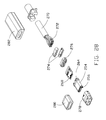
- FIG. 28 is a detailed front exploded perspective view of the plug connector of FIG. 21(A) .
- FIG. 29 is a cross-sectional view of the assembled receptacle connector and plug connector of FIG. 21(A) .
- FIG. 30(A) is a front assembled perspective view of a third embodiment of the receptacle connector mounted upon a printed circuit board according to the invention.
- FIG. 30(B) is a rear assembled perspective view of the receptacle connector mounted upon the printed circuit board of FIG. 30(A) .
- FIG. 31(A) is a front disassembled perspective view of the receptacle connector away from the printed circuit board of FIG. 30(A) .
- FIG. 31(B) is a rear disassembled perspective view of the receptacle connector away from the printed circuit board of FIG. 39(B) .
- FIG. 32(A) is a front exploded perspective view of the terminal module of the receptacle connector of FIG. 30(A) .
- FIG. 32(B) is a rear exploded perspective view of the terminal module of the receptacle connector of FIG. 32(A) .
- FIG. 33(A) is a front exploded perspective view of the receptacle connector of FIG. 30(A) .
- FIG. 33(B) is a rear exploded perspective view of the receptacle connector of FIG. 33(A) .
- FIG. 34(A) is a further front exploded perspective view of the receptacle connector of FIG. 33(A) .
- FIG. 34(B) is a further rear exploded perspective view of the receptacle connector of FIG. 33(B) .
- FIG. 35(A) is a further front exploded perspective view of the receptacle connector of FIG. 34(A) .
- FIG. 35(B) is a further rear exploded perspective view of the receptacle connector of FIG. 34(B) .
- FIG. 36 is a front view of the receptacle connector mounted upon the printed circuit board of FIG. 30(A) .
- FIG. 37 is a cross-sectional view of the receptacle connector mounted upon the printed circuit board of 30 (A).
- FIG. 38 is an assembled perspective view of the plug connector and the receptacle connector mounted upon the printed circuit board according to a fourth embodiment of the invention.
- FIG. 39 is a disassembled perspective view of the plug connector and the receptacle connector mounted upon the printed circuit board of FIG. 38 .
- FIG. 40 is a front perspective view of the plug connector of FIG. 38
- FIG. 41 is a front exploded perspective view of the plug connector of FIG. 40 .
- FIG. 42 is a further front exploded perspective view of the plug connector of FIG. 41 .
- FIG. 43 is a further front exploded perspective view of the front mating portion of the plug connector of FIG. 41 .
- FIG. 44 is a cross-section al view of the disassembled plug connector and receptacle connector of FIG. 39 .
- FIG. 45 is a cross-sectional view of the assembled plug connector and receptacle connector of FIG. 37 .
- FIG. 46 is an assembled perspective view of the plug connector and the receptacle connector mounted upon the printed circuit board according to a fifth embodiment of the invention.
- FIG. 47 is a disassembled perspective view of the plug connector and receptacle connector mounted upon the printed circuit board of FIG. 46 .
- FIG. 48 is a front perspective view of the plug connector of FIG. 46 .
- FIG. 49 is a front exploded perspective view of the plug connector of FIG. 48 .
- FIG. 50 is a further front exploded perspective view of the plug connector of FIG. 49 .
- FIG. 51 is a cross-sectional view of the disassembled plug connector and receptacle connector of FIG. 47 .
- FIG. 52 is a cross-sectional view of the assembled plug connector and receptacle connector of FIG. 46 .
- FIG. 53(A) is a perspective view of the shell of the plug connector of another embodiment of the invention.
- FIG. 53(B) is a cross-sectional view of the shell of the plug connector and the shield of the receptacle connector according to another embodiment of the invention.
- FIGS. 1 through 14 illustrate a first embodiment of the invention.
- FIGS. 1-2 (B) show a plug connector 10 mated with a receptacle connector 50 mounted in a notch 102 of a printed circuit board. 100 .
- the receptacle connector 50 includes an insulative housing 52 with a mating tongue 54 forwardly extending in a capsular mating cavity 57 of a metallic shield 56 which encloses the housing 52 .
- Opposite upper and lower rows of contacts 58 are disposed in the housing 52 with corresponding contacting sections 60 exposed upon opposite surfaces of the mating tongue 54 in a diagonally symmetrical arrangement mechanically and electrically so as to allow a so-called flappable insertion of the plug connector 10 thereinto.
- a step structure 62 is formed around a root of the mating tongue 54 .
- a one piece metallic EMI collar 64 includes a loop structure 66 intimately surrounding the step structure 62 .
- the collar 64 further includes an L-shaped extending plate 65 equipped with embossments 63 thereon and received in the recess 61 of the lower piece 72 of the housing 52 (illustrated later) for mechanically and electrically connecting to the shield 56 .
- the housing 52 is composed of the upper piece 70 and a lower piece 72 commonly sandwiching therebeween a middle piece 74 which forms the mating tongue 54 .
- the upper row contacts 58 are associated with the upper piece 70
- the lower row contacts 58 are associated with a lower piece 72
- the shielding plate 76 is associated with the middle piece 74 via an insert molding process wherein the contacting sections 60 of the upper row contacts 58 and those of the lower rows contacts 58 are seated upon opposite upper surface and lower surface of the mating tongue 54 , respectively, as mentioned before.
- the housing 52 and the associated contacts 58 may be deemed wholly as a so-called terminal module implying the terminals being integrally formed within an insulator.
- a rear portion of the step structure 62 is removed to have a front edge region 71 of the upper piece 70 and the front edge region 73 of the lower piece 72 sandwiched between the middle piece 74 and the loop structure 66 of the EMI collar 64 so as to enhance the strength during mating under some bending.
- the shielding plate 76 defines an opening 77 and a thinner area 78 for both securing and impedance consideration, and further a pair of mounting legs 79 so as to efficiently separate the upper row contacts 58 and the lower row contacts 58 from each other wherein the upper row contacts 58 form the surface mount type tail sections while the lower row contacts 58 form the through hole type tail sections.
- the thinner area 78 may be totally removed from the shielding plate 76 .
- the lower piece 72 includes a pair of mounting posts 80 receiving in the corresponding through hole for mounting the housing 52 to the printed circuit board 100 .
- the lower piece 72 further forms a pair of recessions 49 to receive the corresponding retention tangs 37 of the shield 56 .
- the middle piece 74 forms a pair of recesses 82 to respectively receive the corresponding protrusions 84 of the upper piece 70 and the lower piece 72 for securing the upper piece 70 , the lower piece 72 and the middle piece 74 therebetween in a stacked manner
- the upper piece 70 further include a pair of downward assembling poles 84 received in the corresponding alignment holes 86 of the middle piece 74
- the lower piece 72 further includes an upward assembling pole 85 received in the corresponding alignment holes 86 of the middle piece 74
- the lower piece 72 further forms a pair of upward locating posts 87 received within the corresponding recesses 89 in the upper piece 70 .
- the lower piece 72 defines a plurality of through holes 91 and 93 to receive the tail sections of the lower row contacts 58 and the mounting legs 79 of the shielding plate 76 to extend therethough as an alignment spacer.
- the shielding plate 76 forms a front edge section 69 extending forwardly beyond a front edge of the mating tongue 54 for anti-mismating consideration, and a pair of lateral edge sections 67 extending either beyond or behind the side edge of the mating tongue 54 for locking with a latch 39 of the plug connector 10 (illustrated later).
- the latch 39 may continuously contact the lateral edge sections 67 during the mating procedure from the initial mating position around the corner of the shielding plate 76 to the final locking position around a notch structure of the lateral edge section 67 .
- the shielding plate 76 is essentially multifunctional to perform shielding, grounding, reinforcing, anti-mis-mating and locking.
- a metallic bracket 95 is soldered under the shield 56 and forms a pair of supporting legs 97 mounted into the through hole 103 of the printed circuit board 100 for supporting the receptacle connector 50 within the notch 102 of the printed circuit board 100 .
- the shield 56 further includes an upside-down U-shaped structure (not labeled) on a rear portion covering the rear portion of the housing 52 with a pair of mounting legs 55 received in the through holes 104 for mounting to the printed circuit board 100 and a pair of locking tabs 59 received in the recesses 99 of the upper piece 70 after the shield 56 is rearwardly assembled to the housing 52 in a front-to-back direction.
- the mounting leg 79 of the shielding plate 76 share the same through hole with the neighboring grounding contact tail for enhancing grounding effect.
- the plug connector 10 includes an insulative housing 12 having a capsular front contour with a rectangular receiving cavity 14 therein and enclosed in a metallic shell 16 .
- Opposite upper and lower rows of contacts 18 are disposed in the corresponding passageways 32 of the housing with corresponding contacting sections 20 extending into the receiving cavity 14 wherein the upper and lower rows of contacts 18 are diagonally symmetrically arranged with each other in both electrical and mechanical arrangement so as to meet the so-called flappable mating, i.e., the dual opposite orientations.
- a pair of metallic upper and lower EMI (Electro-Magnetic Interference) spring plates 22 are enclosed in the shell 16 , and each of the EMI spring plates 22 is sandwiched between the shell 16 and the housing 12 and includes a front resilient region 24 extending inwardly toward and into the receiving cavity 14 and in front of the contacting sections 20 , a rear abutting region 26 to abut against the shell 16 , and a pair of side retention regions 28 retainably engaged within corresponding side portions of the housing 12 .
- a pair of tapes 30 are disposed upon two opposite sides of the housing 12 so as to isolate the contacting section 20 from the shell 16 .
- a spacer 34 is located behind the housing and defines a plurality of passages 35 through which the tail sections 21 of the contacts 18 rearwardly extend.
- a recessed region 36 is formed in a rear face of the spacer 34 to receive a front edge region of a paddle card 38 wherein the tail sections 21 of the contacts 18 extending through the corresponding passages 35 , are soldered upon the corresponding pads 37 .
- the spacer 34 forms a forward extending blade 31 with a pair of forward protrusions 33 on two sides to be commonly inserted into a back side of the housing 12 wherein the protrusions 33 of the blade 31 are essentially received in the side slots 13 of the housing 12 .
- a U-shaped metallic latch 39 of a blanking type received in the side slots 13 of the housing 12 with a pair of locking heads 40 extending into the two opposite lateral sides of the receiving cavity 14 to lock with the lateral edge sections 67 of the shielding plate 76 of the receptacle connector 50 during mating. Understandably, the latch 39 is restrained by the blade 31 , the comb structures on the blade 31 , the protrusions 33 of the blade 31 , the slots 13 and an interior rear face of the housing 12 .
- a cable 41 behind the paddle card 38 encloses a plurality of wires 42 regulated by a pair of organizer 43 to be soldered upon a rear region of the paddle card 38 .
- an auxiliary rear shell 17 grasps the shell 16 to shield the paddle card 38
- a clipper 44 grasps the rear shell 17 and further the cable 41 behind the paddle card 38 .
- Opposite front overcoat 45 and rear overcoat or strain relief 46 are overmolded upon the rear shell 17 and the clipper 44 , respectively.
- a cover 47 essentially fully covers the clipper 44 , the front overcoat 45 and the rear overcoat 46 .
- the mating tongue 54 is received in the receiving cavity 14 with the corresponding contacting sections 60 of the contacts 58 of the receptacle connector 50 connected to the contacting sections 20 of the contacts 18 of the plug connector 10 wherein the latch 39 is locked with the shielding plate 76 , and the front resilient region 24 of the spring plate 22 contacts the collar 64 .
- a customized receptacle connector 200 includes a terminal module 202 essentially composed of the upper part 204 , a lower part 206 and a middle part 208 sandwiched therebetween wherein the upper part 204 includes an upper insulator 210 with integrally formed upper contacts 212 via a first stage insert molding process, the lower part 206 includes a lower insulator 214 with integrally formed lower contacts 216 via another first stage insert molding process, and the middle part 208 includes a shielding plate 218 positioned between the upper part 204 and the lower part 206 and integrally formed with a middle insulator 220 which further binds the upper part 204 and the lower part 206 together.
- the shielding plate 218 forms a pair of lateral locking edges 222 to latch the locking head of the corresponding latch of the plug (illustrated later).
- a pair of collars 224 are attached to a root of the mating tongue 226 .
- a metallic shield 228 encloses and secures to the terminal module 202 .
- a metallic bracket 230 is secured to the shield 228 to mount the receptacle connector 200 upon the printed circuit board.
- the new feature of the embodiment is to forms an identification protrusion 229 around a front opening of the mating cavity 232 which is formed by the shield 228 and receives the mating tongue 226 therein.
- the identification protrusion 229 is in a shape of a tab, the tab is split the shield and bending into the mating cavity to function as the identification protrusion 229 , the tab extends in the front-to-back direction and runs through the front edge of the metallic shell.
- the customized plug connector 250 includes an insulative housing 252 enclosed within a metallic shell 254 to be commonly received within the mating cavity 232 of the receptacle connector 200 .
- the insulative housing 252 forms a receiving cavity 256 to receive the mating tongue 226 therein.
- Two rows of contacts 258 are disposed in the housing 252 with contacting sections exposed within the receiving cavity 256 .
- a U-shaped metallic latch 260 is assembled to the housing 252 with a pair of locking heads 262 extending into the receiving cavity 256 .
- a spacer 264 is located behind the housing 252 to allow tails of the contacts 258 to rearwardly extend.
- a pair of spring plates (not shown) are attached to the housing 252 and extending into the receiving cavity 256 .
- a pair of tapes 266 cover the corresponding spring plates for isolating the pair of spring plates from the shell 254 .
- a paddle card 268 is located behind the spacer 264 and the tails of the contacts 258 are soldered upon a front region of the paddle card 268 .
- a cable 270 includes a plurality of wires 272 regulated by a rear organizer 274 and a front organizer 276 and soldered upon a rear region of the paddle card 268 wherein the rear organizer 274 includes two parts assembled to each other in a vertical direction while the front organizer 276 is molded upon the rear region of the paddle card 268 .
- a rear shell 278 is attached to a rear side of the shell 254 with an inner mold 280 applied thereon, and an outer jacket 282 is formed upon the whole set to further cover the cable 270 , the rear organizer 274 , the front organizer 276 , the paddle card 268 and the rear shell 278 .
- the feature of the plug connector 250 is to form a slot 284 in a one primary wall of the shell 254 to receive the protrusion 229 of the shield 228 of the receptacle connector 200 during mating. Understandably, if a flippable mating is desired, another notch may be formed in another primary wall opposite to the existing slot 284 , as disclosed in the aforementioned application Ser. No. 14/273,559.
- the regular/standard plug connector which is not equipped with the slot in the shell as disclosed in the first embodiment of the instant invention, can not be incautiously inserted into the featured receptacle connector 200 of this embodiment even if the rough contour and dimension of the mating interface of these two embodiments are essentially same with each other except existence of the slot 280 , thus achieving an anti-mismating function.
- the plug connector 250 may be optionally inserted into the regular receptacle connector as disclosed in the first embodiment of the instant invention, thus allowing “one way” variable mating of the plug connector 250 to diversify mating applications among the standard type connector mating and non-standard but related type connector mating.
- FIGS. 30(A) - 37 show a third embodiment of the receptacle connector very similar to the second embodiment except the identification protrusion structure.
- the customized receptacle connector 300 is mounted upon the printed circuit board 350 and includes a terminal module 302 enclosed within the metallic shield 328 .
- the terminal module 302 includes an upper part 304 composed of the upper contacts 312 integrally formed with an upper insulator 310 via a first stage insert molding process, a lower part 306 composed of the lower contacts 316 integrally formed with the lower insulator 314 via another first stage inset molding process, and a middle part 308 sandwiched between the upper part 304 and the lower part 306 with a shielding plate 318 integrally formed with a middle insulator 320 via a second stage insert molding process wherein the middle insulator 320 is further secured with the upper part 304 and the lower part 306 .
- the shielding plate 318 is equipped with a pair of lateral edge sections 322 for locking with the latch of the plug (illustrated later).
- the terminal module 302 forms a mating tongue 326 within the mating cavity 332 defined by the shield 328 which forms a lump-like or dimple-like identification protrusion 329 in stead of the tab-like identification protrusion 229 shown in the previous embodiment.
- the lump-like protrusion 329 via the deforming process may keep completeness of the shield 328 , compared with the tab-lie protrusion 229 which is split from the shield 328 with a gap therebetween.
- the protrusion 229 / 329 may be formed on the top wall of the shield 228 / 328 instead of on the bottom wall thereof.
- the identification protrusion may be formed by the bracket 230 / 330 when the corresponding position of the shield leaves an enough space for allowing such an identification protrusion formed on the shield to extend therethrough into the mating cavity. It is also noted that in this embodiment the identification protrusion is essentially immovable. Anyhow, in other embodiments, such an identification protrusion may be formed at a distal end of the spring arm unitarily formed on either the shield or the bracket, and the corresponding non-standard or customized plug connector may be formed with a slot or other guiding surfaces to eventually outwardly deflect such an identification protrusion when fully mated while the standard plug connector lacking such a slot or guiding surfaces may not outwardly deflect such an identification protrusion but being stopped thereby.
- the customized plug connector 250 disclosed in the previous embodiment may be improperly inserted into the standard/regular receptacle connector disclosed in the first embodiment, unless the customized plug connector 250 is intentionally designed to mate with both the standard receptacle connector and the customized receptacle connector. To avoid this situation, the customized plug may be equipped with some features for not mating with the standard receptacle connector.
- FIGS. 38-45 show a fourth embodiment of the customized plug connector 400 for mating with the customized receptacle connector 450 mounted upon the printed circuit board 460 and having the identification protrusion 452 on the shield 454 .
- the plug connector 400 includes an insulative housing 402 defining a receiving cavity 404 therein. Two rows of contacts 406 are disposed in the housing 402 and by two sides of the receiving cavity 404 .
- a U-shaped latch 408 is assembled to the housing 402 with corresponding locking heads 410 extending into the receiving cavity 404 for locking to the corresponding lateral side edges of the shielding plate of the customized receptacle connector 450 .
- An insulative spacer 412 is located behind the latch 408 to receive the paddle 421 card and the tails of the contacts 406 .
- a pair of spring plates 414 and a pair of tapes 416 are disposed in the housing 402 similar to those in the aforementioned other embodiments.
- a metallic front shell 418 encloses the housing 402 with a slot 420 in the front edge region thereof.
- a cable 430 has a plurality of wires 432 soldered upon the paddle card 421 .
- An organizer 423 is seated upon the paddle card 421 to regulate the wires 432 , and a middle shell 422 and a rear shell 424 are further attached to the paddle card 421 and the cable 430 .
- An outer jacket 436 is applied upon the front shell 418 , the middle shell 422 and the rear shell 424 . Different from that in the previous embodiment, the outer jacket 436 further forms a forwardly protruding ring structure or protruding element 438 to enclose a front section of the corresponding receptacle connector 450 .
- the receptacle connector 450 is generally located behind a wall A (as shown in the dashed line in FIGS. 44 and 45 ) of the case such as a desktop computer, and such a wall with the customized receptacle connector 450 behind may be equipped with an opening to allow said ring structure 438 to extend during mating.
- the wall with the standard receptacle connector behind lacks such an opening so as not to allow the customized plug connector 400 to be fully inserted into the mating cavity 456 of the customized receptacle connector 450 .
- the standard plug connector as shown in the first embodiment without such a ring structure thereof may be fully inserted into the corresponding standard receptacle connector behind such a wall.
- the slot 439 formed in the ring structure 438 is for an orientation purpose when the plug connector 400 is not intended to be flippable with regard to the receptacle connector 450 .
- FIGS. 46-52 show a fifth embodiment of the plug connector 500 almost fully same with the plug connector 400 except the ring structure 438 is replaced with a protruding plate or protruding element 538 . Understandably, the wall of the case requires the opening only corresponding to the protruding plate 538 . In this embodiment, the protruding plate 538 also functions as the orientation means to guide mating between the plug connector and the receptacle connector.
- the previous embodiment may not only allow the customized plug connector to be mated with the corresponding customized receptacle but also preclude the standard plug connector from being inserted into the customized receptacle connector and the customized plug connector from being inserted into the standard receptacle connector. Anyhow, the previous embodiment requires to alter the outer jacket of the customized plug connector.
- FIGS. 53 (A)- 53 (B) show other approaches wherein in FIG. 53(A) the shell 700 of the customized plug connector can unitarily form a recess 702 and a protrusion 704 , and the customized receptacle connector may also form the similar structures correspondingly for coupling.
- FIG. 53(B) also shows the similar concept to implement the same function within a limited space, wherein the top wall 81 of the shield of the outer receptacle connector has a downward tab 811 split from the shield, the top wall 82 of the shield of the inner plug connector has an upward tab 821 split from the shield.
Abstract
A receptacle connector assembly includes an insulative housing defining base with a mating tongue forwardly extending therefrom in a front-to-back direction, a plurality of contacts disposed in the housing with contacting sections exposed upon the mating tongue, a metallic shield enclosing the housing to define a capsular mating cavity in which the mating tongue is disposed and a metallic shielding plate embedded within the mating tongue and defining a pair of lateral edge sections. The metallic shield defines an identification protrusion extending into the mating cavity so as to preclude from mating with a standard plug connector, which has a contour compliant with said capsular mating cavity, but with a customized plug connector which also has a contour compliant with said capsular mating cavity and further with a corresponding slot to receive said identification protrusion.
Description
This application is a continuation-in-part of the co-pending application Ser. No. 14/558,732 filed Dec. 3, 2014 and Ser. No. 14/688,993 filed Apr. 16, 2015 and the instant application further claims the benefit of, and priority to, U.S. Provisional Patent Application No. 62/044,195, filed Aug. 30, 2014, the contents of which are incorporated entirely herein by reference.
1. Field of the Invention
The present invention relates to an electrical connector, and more particularly to a flippable plug connector used with a receptacle connector.
2. Description of Related Art
In the previously filed provisional applications, the plug connector is “flippable” whereas we turn the plug over and it functions the same top and bottom. In order to be able to handle switching of the super speed signaling, a MUX (or SS switch) is built into the silicon. This can be costly and also cause some additional degredation in the super speed signals. Recently, a proposal for use with the future USB (Universal Serial Bus) was presented.
Hence, a new and simple electrical plug connector and the complementary receptacle connector are desired to improve those disclosed in the aforementioned proposal.
Accordingly, the object of the present invention is to provide a receptacle connector assembly for use with a plug comprises an insulative housing defining base with a mating tongue forwardly extending therefrom in a front-to-back direction, a plurality of contacts disposed in the housing with contacting sections exposed upon the mating tongue, a metallic shield enclosing the housing to define a capsular mating cavity in which said mating tongue is disposed and a metallic shielding plate embedded within said mating tongue and defining a pair of lateral edge sections configured to be adapted to be locked with a latch of the plug. The metallic shield defines an identification protrusion extending into the mating cavity so as to preclude from mating with a standard plug connector, which has a contour compliant with said capsular mating cavity, but with a customized plug connector which also has a contour compliant with said capsular mating cavity and further with a corresponding slot to receive said identification protrusion.
The plug connector comprises an insulative housing defining a receiving cavity, a plurality of contacts disposed in the housing with contacting sections exposed in said receiving cavity, and a metallic shell fitly enclosing said housing. The shell defines a capsular contour with a slot extending along a front-to-back direction from a front edge thereof so as to distinguish from a standard plug connector having the same capsular contour while without said slot; whereby the plug connector is allowed to be mated with a customized receptacle connector which forms a mating cavity complaint with said capsular contour while further equipped with an inward protrusion.
Other objects, advantages and novel features of the invention will become more apparent from the following detailed description when taken in conjunction with the accompanying drawings.
Reference will now be made in detail to the preferred embodiment of the present invention. FIGS. 1 through 14 illustrate a first embodiment of the invention. FIGS. 1-2 (B) show a plug connector 10 mated with a receptacle connector 50 mounted in a notch 102 of a printed circuit board. 100. Referring to FIGS. 3-9 , the receptacle connector 50 includes an insulative housing 52 with a mating tongue 54 forwardly extending in a capsular mating cavity 57 of a metallic shield 56 which encloses the housing 52. Opposite upper and lower rows of contacts 58 are disposed in the housing 52 with corresponding contacting sections 60 exposed upon opposite surfaces of the mating tongue 54 in a diagonally symmetrical arrangement mechanically and electrically so as to allow a so-called flappable insertion of the plug connector 10 thereinto. A step structure 62 is formed around a root of the mating tongue 54. A one piece metallic EMI collar 64 includes a loop structure 66 intimately surrounding the step structure 62. The collar 64 further includes an L-shaped extending plate 65 equipped with embossments 63 thereon and received in the recess 61 of the lower piece 72 of the housing 52 (illustrated later) for mechanically and electrically connecting to the shield 56.
The housing 52 is composed of the upper piece 70 and a lower piece 72 commonly sandwiching therebeween a middle piece 74 which forms the mating tongue 54. The upper row contacts 58 are associated with the upper piece 70, the lower row contacts 58 are associated with a lower piece 72 and the shielding plate 76 is associated with the middle piece 74 via an insert molding process wherein the contacting sections 60 of the upper row contacts 58 and those of the lower rows contacts 58 are seated upon opposite upper surface and lower surface of the mating tongue 54, respectively, as mentioned before. Understandably, the housing 52 and the associated contacts 58 may be deemed wholly as a so-called terminal module implying the terminals being integrally formed within an insulator. A rear portion of the step structure 62 is removed to have a front edge region 71 of the upper piece 70 and the front edge region 73 of the lower piece 72 sandwiched between the middle piece 74 and the loop structure 66 of the EMI collar 64 so as to enhance the strength during mating under some bending. In this embodiment, the shielding plate 76 defines an opening 77 and a thinner area 78 for both securing and impedance consideration, and further a pair of mounting legs 79 so as to efficiently separate the upper row contacts 58 and the lower row contacts 58 from each other wherein the upper row contacts 58 form the surface mount type tail sections while the lower row contacts 58 form the through hole type tail sections. In an alternate embodiment, the thinner area 78 may be totally removed from the shielding plate 76. The lower piece 72 includes a pair of mounting posts 80 receiving in the corresponding through hole for mounting the housing 52 to the printed circuit board 100. The lower piece 72 further forms a pair of recessions 49 to receive the corresponding retention tangs 37 of the shield 56.
In this embodiment, the middle piece 74 forms a pair of recesses 82 to respectively receive the corresponding protrusions 84 of the upper piece 70 and the lower piece 72 for securing the upper piece 70, the lower piece 72 and the middle piece 74 therebetween in a stacked manner wherein the upper piece 70 further include a pair of downward assembling poles 84 received in the corresponding alignment holes 86 of the middle piece 74, and the lower piece 72 further includes an upward assembling pole 85 received in the corresponding alignment holes 86 of the middle piece 74, and the lower piece 72 further forms a pair of upward locating posts 87 received within the corresponding recesses 89 in the upper piece 70. In this embodiment, the lower piece 72 defines a plurality of through holes 91 and 93 to receive the tail sections of the lower row contacts 58 and the mounting legs 79 of the shielding plate 76 to extend therethough as an alignment spacer. Notably, the shielding plate 76 forms a front edge section 69 extending forwardly beyond a front edge of the mating tongue 54 for anti-mismating consideration, and a pair of lateral edge sections 67 extending either beyond or behind the side edge of the mating tongue 54 for locking with a latch 39 of the plug connector 10 (illustrated later). Understandably, the latch 39 may continuously contact the lateral edge sections 67 during the mating procedure from the initial mating position around the corner of the shielding plate 76 to the final locking position around a notch structure of the lateral edge section 67. In brief, the shielding plate 76 is essentially multifunctional to perform shielding, grounding, reinforcing, anti-mis-mating and locking. A metallic bracket 95 is soldered under the shield 56 and forms a pair of supporting legs 97 mounted into the through hole 103 of the printed circuit board 100 for supporting the receptacle connector 50 within the notch 102 of the printed circuit board 100. The shield 56 further includes an upside-down U-shaped structure (not labeled) on a rear portion covering the rear portion of the housing 52 with a pair of mounting legs 55 received in the through holes 104 for mounting to the printed circuit board 100 and a pair of locking tabs 59 received in the recesses 99 of the upper piece 70 after the shield 56 is rearwardly assembled to the housing 52 in a front-to-back direction. Notably, the mounting leg 79 of the shielding plate 76 share the same through hole with the neighboring grounding contact tail for enhancing grounding effect.
Referring to FIGS. 10-13 (B) and further FIG. 14 , the plug connector 10 includes an insulative housing 12 having a capsular front contour with a rectangular receiving cavity 14 therein and enclosed in a metallic shell 16. Opposite upper and lower rows of contacts 18 are disposed in the corresponding passageways 32 of the housing with corresponding contacting sections 20 extending into the receiving cavity 14 wherein the upper and lower rows of contacts 18 are diagonally symmetrically arranged with each other in both electrical and mechanical arrangement so as to meet the so-called flappable mating, i.e., the dual opposite orientations. A pair of metallic upper and lower EMI (Electro-Magnetic Interference) spring plates 22 are enclosed in the shell 16, and each of the EMI spring plates 22 is sandwiched between the shell 16 and the housing 12 and includes a front resilient region 24 extending inwardly toward and into the receiving cavity 14 and in front of the contacting sections 20, a rear abutting region 26 to abut against the shell 16, and a pair of side retention regions 28 retainably engaged within corresponding side portions of the housing 12. A pair of tapes 30 are disposed upon two opposite sides of the housing 12 so as to isolate the contacting section 20 from the shell 16. A spacer 34 is located behind the housing and defines a plurality of passages 35 through which the tail sections 21 of the contacts 18 rearwardly extend. A recessed region 36 is formed in a rear face of the spacer 34 to receive a front edge region of a paddle card 38 wherein the tail sections 21 of the contacts 18 extending through the corresponding passages 35, are soldered upon the corresponding pads 37. The spacer 34 forms a forward extending blade 31 with a pair of forward protrusions 33 on two sides to be commonly inserted into a back side of the housing 12 wherein the protrusions 33 of the blade 31 are essentially received in the side slots 13 of the housing 12. A U-shaped metallic latch 39 of a blanking type received in the side slots 13 of the housing 12 with a pair of locking heads 40 extending into the two opposite lateral sides of the receiving cavity 14 to lock with the lateral edge sections 67 of the shielding plate 76 of the receptacle connector 50 during mating. Understandably, the latch 39 is restrained by the blade 31, the comb structures on the blade 31, the protrusions 33 of the blade 31, the slots 13 and an interior rear face of the housing 12.
A cable 41 behind the paddle card 38, encloses a plurality of wires 42 regulated by a pair of organizer 43 to be soldered upon a rear region of the paddle card 38. Via the protrusions and openings (not labeled), an auxiliary rear shell 17 grasps the shell 16 to shield the paddle card 38, and a clipper 44 grasps the rear shell 17 and further the cable 41 behind the paddle card 38. Opposite front overcoat 45 and rear overcoat or strain relief 46 are overmolded upon the rear shell 17 and the clipper 44, respectively. Finally, a cover 47 essentially fully covers the clipper 44, the front overcoat 45 and the rear overcoat 46. During mating, the mating tongue 54 is received in the receiving cavity 14 with the corresponding contacting sections 60 of the contacts 58 of the receptacle connector 50 connected to the contacting sections 20 of the contacts 18 of the plug connector 10 wherein the latch 39 is locked with the shielding plate 76, and the front resilient region 24 of the spring plate 22 contacts the collar 64.
Referring to FIGS. 15-20 , according to a second embodiment similar to the first embodiment and much closer to the second embodiment of the aforementioned provisional application 62/001,084 filed May 21, 2014, a customized receptacle connector 200 includes a terminal module 202 essentially composed of the upper part 204, a lower part 206 and a middle part 208 sandwiched therebetween wherein the upper part 204 includes an upper insulator 210 with integrally formed upper contacts 212 via a first stage insert molding process, the lower part 206 includes a lower insulator 214 with integrally formed lower contacts 216 via another first stage insert molding process, and the middle part 208 includes a shielding plate 218 positioned between the upper part 204 and the lower part 206 and integrally formed with a middle insulator 220 which further binds the upper part 204 and the lower part 206 together.
Similar to the embodiments disclosed in the aforementioned applications, the shielding plate 218 forms a pair of lateral locking edges 222 to latch the locking head of the corresponding latch of the plug (illustrated later). A pair of collars 224 are attached to a root of the mating tongue 226. A metallic shield 228 encloses and secures to the terminal module 202. A metallic bracket 230 is secured to the shield 228 to mount the receptacle connector 200 upon the printed circuit board. The new feature of the embodiment is to forms an identification protrusion 229 around a front opening of the mating cavity 232 which is formed by the shield 228 and receives the mating tongue 226 therein. The identification protrusion 229 is in a shape of a tab, the tab is split the shield and bending into the mating cavity to function as the identification protrusion 229, the tab extends in the front-to-back direction and runs through the front edge of the metallic shell.
Correspondingly, referring to FIGS. 21(A) -29, the customized plug connector 250 includes an insulative housing 252 enclosed within a metallic shell 254 to be commonly received within the mating cavity 232 of the receptacle connector 200. The insulative housing 252 forms a receiving cavity 256 to receive the mating tongue 226 therein. Two rows of contacts 258 are disposed in the housing 252 with contacting sections exposed within the receiving cavity 256. A U-shaped metallic latch 260 is assembled to the housing 252 with a pair of locking heads 262 extending into the receiving cavity 256. A spacer 264 is located behind the housing 252 to allow tails of the contacts 258 to rearwardly extend. A pair of spring plates (not shown) are attached to the housing 252 and extending into the receiving cavity 256. A pair of tapes 266 cover the corresponding spring plates for isolating the pair of spring plates from the shell 254.
A paddle card 268 is located behind the spacer 264 and the tails of the contacts 258 are soldered upon a front region of the paddle card 268. A cable 270 includes a plurality of wires 272 regulated by a rear organizer 274 and a front organizer 276 and soldered upon a rear region of the paddle card 268 wherein the rear organizer 274 includes two parts assembled to each other in a vertical direction while the front organizer 276 is molded upon the rear region of the paddle card 268. A rear shell 278 is attached to a rear side of the shell 254 with an inner mold 280 applied thereon, and an outer jacket 282 is formed upon the whole set to further cover the cable 270, the rear organizer 274, the front organizer 276, the paddle card 268 and the rear shell 278.
The feature of the plug connector 250 is to form a slot 284 in a one primary wall of the shell 254 to receive the protrusion 229 of the shield 228 of the receptacle connector 200 during mating. Understandably, if a flippable mating is desired, another notch may be formed in another primary wall opposite to the existing slot 284, as disclosed in the aforementioned application Ser. No. 14/273,559. Differently, the regular/standard plug connector which is not equipped with the slot in the shell as disclosed in the first embodiment of the instant invention, can not be incautiously inserted into the featured receptacle connector 200 of this embodiment even if the rough contour and dimension of the mating interface of these two embodiments are essentially same with each other except existence of the slot 280, thus achieving an anti-mismating function. Oppositely, the plug connector 250 may be optionally inserted into the regular receptacle connector as disclosed in the first embodiment of the instant invention, thus allowing “one way” variable mating of the plug connector 250 to diversify mating applications among the standard type connector mating and non-standard but related type connector mating.
The terminal module 302 forms a mating tongue 326 within the mating cavity 332 defined by the shield 328 which forms a lump-like or dimple-like identification protrusion 329 in stead of the tab-like identification protrusion 229 shown in the previous embodiment. Understandably, the lump-like protrusion 329 via the deforming process may keep completeness of the shield 328, compared with the tab-lie protrusion 229 which is split from the shield 328 with a gap therebetween. As mentioned earlier, the protrusion 229/329 may be formed on the top wall of the shield 228/328 instead of on the bottom wall thereof. Under such a situation, the identification protrusion may be formed by the bracket 230/330 when the corresponding position of the shield leaves an enough space for allowing such an identification protrusion formed on the shield to extend therethrough into the mating cavity. It is also noted that in this embodiment the identification protrusion is essentially immovable. Anyhow, in other embodiments, such an identification protrusion may be formed at a distal end of the spring arm unitarily formed on either the shield or the bracket, and the corresponding non-standard or customized plug connector may be formed with a slot or other guiding surfaces to eventually outwardly deflect such an identification protrusion when fully mated while the standard plug connector lacking such a slot or guiding surfaces may not outwardly deflect such an identification protrusion but being stopped thereby.
It is noted that the customized plug connector 250 disclosed in the previous embodiment may be improperly inserted into the standard/regular receptacle connector disclosed in the first embodiment, unless the customized plug connector 250 is intentionally designed to mate with both the standard receptacle connector and the customized receptacle connector. To avoid this situation, the customized plug may be equipped with some features for not mating with the standard receptacle connector.
A cable 430 has a plurality of wires 432 soldered upon the paddle card 421. An organizer 423 is seated upon the paddle card 421 to regulate the wires 432, and a middle shell 422 and a rear shell 424 are further attached to the paddle card 421 and the cable 430. An outer jacket 436 is applied upon the front shell 418, the middle shell 422 and the rear shell 424. Different from that in the previous embodiment, the outer jacket 436 further forms a forwardly protruding ring structure or protruding element 438 to enclose a front section of the corresponding receptacle connector 450. Understandably, the receptacle connector 450 is generally located behind a wall A (as shown in the dashed line in FIGS. 44 and 45 ) of the case such as a desktop computer, and such a wall with the customized receptacle connector 450 behind may be equipped with an opening to allow said ring structure 438 to extend during mating. In opposite, the wall with the standard receptacle connector behind lacks such an opening so as not to allow the customized plug connector 400 to be fully inserted into the mating cavity 456 of the customized receptacle connector 450. On the other hand, the standard plug connector as shown in the first embodiment without such a ring structure thereof may be fully inserted into the corresponding standard receptacle connector behind such a wall. Notably, the slot 439 formed in the ring structure 438 is for an orientation purpose when the plug connector 400 is not intended to be flippable with regard to the receptacle connector 450.
Understandably, the previous embodiment may not only allow the customized plug connector to be mated with the corresponding customized receptacle but also preclude the standard plug connector from being inserted into the customized receptacle connector and the customized plug connector from being inserted into the standard receptacle connector. Anyhow, the previous embodiment requires to alter the outer jacket of the customized plug connector. FIGS. 53 (A)-53(B) show other approaches wherein in FIG. 53(A) the shell 700 of the customized plug connector can unitarily form a recess 702 and a protrusion 704, and the customized receptacle connector may also form the similar structures correspondingly for coupling. Because the recess and the protrusion are simultaneously formed on the shield of the customized receptacle connector and the customized plug connector, the standard plug connector and standard receptacle connector can no longer mis-mated therewith. FIG. 53(B) also shows the similar concept to implement the same function within a limited space, wherein the top wall 81 of the shield of the outer receptacle connector has a downward tab 811 split from the shield, the top wall 82 of the shield of the inner plug connector has an upward tab 821 split from the shield.
It is to be understood, however, that even though numerous characteristics and advantages of the present invention have been set forth in the foregoing description, together with details of the structure and function of the invention, the disclosure is illustrative only, and changes may be made in detail, especially in matters of shape, size, and arrangement of parts within the principles of the invention to the full extent indicated by the broad general meaning of the terms in which the appended claims are expressed. It is noted that the flippable arrangement, i.e., the dual-orientation application, is essentially the prior art with regard to the instant invention, and the invention is to provide the customized arrangement of both the plug connector and the receptacle connector wherein such customized arrangement is preferred to be used in only one orientation application.
Claims (15)
1. A receptacle connector assembly for use with a plug, comprising:
an insulative housing defining base with a mating tongue forwardly extending therefrom in a front-to-back direction;
a plurality of contacts disposed in the housing with contacting sections exposed upon the mating tongue;
a metallic shield enclosing the housing to define a capsular mating cavity in which said mating tongue is disposed; and
a metallic shielding plate embedded within said mating tongue and defining a pair of lateral edge sections configured to be adapted to be locked with a latch of the plug;
wherein the metallic shield defines an identification protrusion extending inwardly into the mating cavity so as to be precluded from mating with a standard plug connector, which has a contour compliant with said capsular mating cavity, but being adapted to be mated with a customized plug connector which also has a contour compliant with said capsular mating cavity and further with a corresponding slot to receive said identification protrusion;
wherein the shield defines a lump or dimple deformed from the shield and protruding into the mating cavity to function as the identification protrusion.
2. The receptacle connector assembly as claimed in claim 1 , wherein the shield defines a tab split therefrom and bending into the mating cavity to function as the identification protrusion, the tab extending in the front-to-back direction and running through the front edge of the metallic shell.
3. The receptacle connector assembly as claimed in claim 1 , wherein said metallic shield further forms another identification protrusion extending outwardly away from the mating cavity and neighboring with said inwardly extending identification protrusion.
4. The receptacle connector assembly as claimed in claim 3 , wherein said another identification protrusion is either a tab or a dimple.
5. A plug connector comprising:
an insulative housing defining a receiving cavity;
a plurality of contacts disposed in the housing with contacting sections exposed in said receiving cavity;
a metallic shell fitly enclosing said housing;
wherein the shell defines a capsular contour with a slot extending along a front-to-back direction from a front edge thereof so as to distinguish from a standard plug connector having the same capsular contour while without said slot; whereby the plug connector is allowed to be mated with a customized receptacle connector which forms a mating cavity compliant with said capsular contour while being further equipped with an inward protrusion;
wherein said plug connector further includes a protrusion preventing said plug connector from being inserted into a standard receptacle connector which defines a mating cavity compliant with said capsular contour;
wherein said protrusion is formed on an outer jacket enclosing said shell;
wherein said protrusion is or a ring structure forwardly extending to surround the shell;
wherein said ring structure forms forwardly extending a slot therein.
6. The plug connector as claimed in claim 5 , wherein said protrusion is a plate forwardly extending in parallel with the shell.
7. The plug connector as claimed in claim 5 , wherein said shell extends forwardly beyond the ring structure.
8. An arrangement for preventing mis-mating between different type receptacle connector and plug connector, comprising:
a standard receptacle connector including a first receptacle housing having a plurality of standard contacts therein and enclosed within a first metallic shield which defines a standard mating cavity therein;
a standard plug connector including a first plug housing having a plurality of standard terminals therein and enclosed within a first metallic shell which is adapted to be received with the standard mating cavity in a flippable manner;
a customized receptacle connector including a second receptacle housing having a plurality of customized contacts therein and enclosed within a second metallic shield which defines a customized mating cavity;
a customized plug connector including a second plug housing having a plurality of customized terminals therein and enclosed within a second metallic shell which is adapted to be received within the customized mating cavity in only one orientation way; wherein
the first metallic shield and the second metallic shield define commonly a same contour so as to have both the standard mating cavity and the customized mating cavity configured same with each other except that said second metallic shield further forms a protrusion inwardly extending into the customized mating cavity; wherein
the first metallic shell and the second metallic shell define a same contour except the second metallic shell further forms a slot to comply with the protrusion; wherein
only the customized plug connector can be mated with the customized receptacle connector due to coupling between the protrusion and the slot while the standard plug connector can not be mated with the customized receptacle connector due to interference between the second metallic shell and the protrusion.
9. The arrangement as claimed in claim 8 , wherein said customized plug connector further includes a protruding element extending around the second metallic shell, and the customized receptacle connector provides space around the first metallic shield to accommodate said protruding element while the standard receptacle connector lacks any accommodation function thereabouts so as to assure that the customized plug connector can not be mated with the standard receptacle connector.
10. The arrangement as claimed in claim 9 , wherein said protruding element is a plate extending forwardly in parallel with the second metallic shell.
11. The arrangement as claimed in claim 9 , wherein said protruding element is unitarily formed with an jacket enclosing said second metallic shell.
12. The arrangement as claimed in claim 9 , wherein said protrusion is either a tab or a dimple.
13. The arrangement as claimed in claim 9 , wherein each of said standard receptacle connector and said customized receptacle connector includes a mating tongue extending forwardly in the corresponding mating cavity, and a metallic shield plate is embedded within the mating tongue with a pair of locking notches in two opposite lateral side edges.
14. The arrangement as claimed in claim 9 , wherein said protruding element is of a ring structure extending forwardly to surround the second metallic shell.
15. The arrangement as claimed in claim 14 , wherein said ring structure is equipped with a forwardly extending slot.
Priority Applications (5)
| Application Number | Priority Date | Filing Date | Title |
|---|---|---|---|
| US14/839,880 US9490579B2 (en) | 2013-07-19 | 2015-08-28 | Flippable Electrical Connector |
| US15/346,642 US9912111B2 (en) | 2013-07-19 | 2016-11-08 | Flippable electrical connector |
| US15/496,002 US9997853B2 (en) | 2013-07-19 | 2017-04-25 | Flippable electrical connector |
| US15/688,920 US10170870B2 (en) | 2013-07-19 | 2017-08-29 | Flippable electrical connector |
| US16/236,357 US10693261B2 (en) | 2013-07-19 | 2018-12-29 | Flippable electrical connector |
Applications Claiming Priority (27)
| Application Number | Priority Date | Filing Date | Title |
|---|---|---|---|
| US201361856077P | 2013-07-19 | 2013-07-19 | |
| US201361857687P | 2013-07-23 | 2013-07-23 | |
| US201361863896P | 2013-08-08 | 2013-08-08 | |
| US201361866037P | 2013-08-14 | 2013-08-14 | |
| US201361867584P | 2013-08-19 | 2013-08-19 | |
| US201361875096P | 2013-09-08 | 2013-09-08 | |
| US201361899276P | 2013-11-03 | 2013-11-03 | |
| US201361916147P | 2013-12-14 | 2013-12-14 | |
| US201361917363P | 2013-12-18 | 2013-12-18 | |
| US201361919681P | 2013-12-20 | 2013-12-20 | |
| US201461926270P | 2014-01-11 | 2014-01-11 | |
| US201461940815P | 2014-02-17 | 2014-02-17 | |
| US201461943310P | 2014-02-22 | 2014-02-22 | |
| US201461949232P | 2014-03-06 | 2014-03-06 | |
| US201461981217P | 2014-04-18 | 2014-04-18 | |
| US201461989508P | 2014-05-06 | 2014-05-06 | |
| US201462001084P | 2014-05-21 | 2014-05-21 | |
| US14/337,180 US9318853B2 (en) | 2013-07-19 | 2014-07-21 | Flippable electrical connector |
| US14/454,737 US9525227B2 (en) | 2012-07-21 | 2014-08-08 | Flippable electrical connector |
| US201462044195P | 2014-08-30 | 2014-08-30 | |
| US14/477,889 US9525223B2 (en) | 2013-07-19 | 2014-09-05 | Flippable electrical connector |
| US14/497,205 US9472910B2 (en) | 2013-07-19 | 2014-09-25 | Flippable electrical connector |
| US14/517,941 US9496662B2 (en) | 2013-07-19 | 2014-10-20 | Flippable electrical connector |
| US14/542,550 US9350126B2 (en) | 2013-07-19 | 2014-11-15 | Electrical connector having a receptacle with a shielding plate and a mating plug with metallic side arms |
| US14/558,732 US9490594B2 (en) | 2013-07-19 | 2014-12-03 | Flippable electrical connector |
| US14/688,993 US9496664B2 (en) | 2013-07-19 | 2015-04-16 | Flippable electrical connector |
| US14/839,880 US9490579B2 (en) | 2013-07-19 | 2015-08-28 | Flippable Electrical Connector |
Related Parent Applications (7)
| Application Number | Title | Priority Date | Filing Date |
|---|---|---|---|
| US14/337,180 Continuation-In-Part US9318853B2 (en) | 2013-07-19 | 2014-07-21 | Flippable electrical connector |
| US14/454,737 Continuation-In-Part US9525227B2 (en) | 2012-07-21 | 2014-08-08 | Flippable electrical connector |
| US14/477,889 Continuation-In-Part US9525223B2 (en) | 2013-07-19 | 2014-09-05 | Flippable electrical connector |
| US14/517,941 Continuation-In-Part US9496662B2 (en) | 2013-07-19 | 2014-10-20 | Flippable electrical connector |
| US14/542,550 Continuation-In-Part US9350126B2 (en) | 2013-07-19 | 2014-11-15 | Electrical connector having a receptacle with a shielding plate and a mating plug with metallic side arms |
| US14/558,732 Continuation-In-Part US9490594B2 (en) | 2013-07-19 | 2014-12-03 | Flippable electrical connector |
| US14/688,993 Continuation-In-Part US9496664B2 (en) | 2013-07-19 | 2015-04-16 | Flippable electrical connector |
Related Child Applications (1)
| Application Number | Title | Priority Date | Filing Date |
|---|---|---|---|
| US15/346,642 Continuation-In-Part US9912111B2 (en) | 2013-07-19 | 2016-11-08 | Flippable electrical connector |
Publications (2)
| Publication Number | Publication Date |
|---|---|
| US20150372424A1 US20150372424A1 (en) | 2015-12-24 |
| US9490579B2 true US9490579B2 (en) | 2016-11-08 |
Family
ID=54870504
Family Applications (1)
| Application Number | Title | Priority Date | Filing Date |
|---|---|---|---|
| US14/839,880 Active US9490579B2 (en) | 2013-07-19 | 2015-08-28 | Flippable Electrical Connector |
Country Status (1)
| Country | Link |
|---|---|
| US (1) | US9490579B2 (en) |
Cited By (14)
| Publication number | Priority date | Publication date | Assignee | Title |
|---|---|---|---|---|
| US20160197443A1 (en) * | 2015-01-06 | 2016-07-07 | Molex, Llc | Electrical connector |
| US20160352047A1 (en) * | 2015-06-01 | 2016-12-01 | Foxconn Interconnect Technology Limited | Cable connector assembly with anti-mismating structure |
| US20160380389A1 (en) * | 2014-02-21 | 2016-12-29 | Lotes Co., Ltd | Electrical connector |
| US20170085021A1 (en) * | 2015-09-23 | 2017-03-23 | Advanced-Connectek Inc. | Electrical receptacle connector |
| US20170149164A1 (en) * | 2014-06-03 | 2017-05-25 | Japan Aviation Electronics Industry, Limited | Connector |
| US20170194750A1 (en) * | 2016-01-06 | 2017-07-06 | Foxconn Interconnect Technology Limited | Electrical connector with device securing shielding plate and insulator together before molding |
| US9893468B2 (en) * | 2016-05-25 | 2018-02-13 | Foxconn Interconnect Technology Limited | Electrical connector assembly having improved shielding shell |
| US10170870B2 (en) * | 2013-07-19 | 2019-01-01 | Foxconn Interconnect Technology Limited | Flippable electrical connector |
| US20190237912A1 (en) * | 2013-07-19 | 2019-08-01 | Foxconn Interconnect Technology Limited | Flippable electrical connector |
| US10992088B2 (en) | 2018-08-25 | 2021-04-27 | Foxconn (Kunshan) Computer Connector Co., Ltd. | Universal Serial Bus Type-C electrical connector having a reduced length |
| US20220037843A1 (en) * | 2020-07-31 | 2022-02-03 | Advanced-Connectek Inc. | Electrical receptacle connector |
| US11296450B2 (en) * | 2019-07-25 | 2022-04-05 | Foxconn (Kunshan) Computer Connector Co., Ltd. | Electrical connector assembly |
| EP4138230A1 (en) * | 2021-08-20 | 2023-02-22 | Japan Aviation Electronics Industry, Limited | Connector assembly |
| EP4177704A4 (en) * | 2020-07-29 | 2024-01-03 | Samsung Electronics Co Ltd | Electronic device comprising reinforcement structure for damage prevention |
Families Citing this family (13)
| Publication number | Priority date | Publication date | Assignee | Title |
|---|---|---|---|---|
| US9350126B2 (en) * | 2013-07-19 | 2016-05-24 | Foxconn Interconnect Technology Limited | Electrical connector having a receptacle with a shielding plate and a mating plug with metallic side arms |
| US9905944B2 (en) * | 2013-07-19 | 2018-02-27 | Foxconn Interconnect Technology Limited | Flippable electrical connector |
| CN204216267U (en) * | 2014-07-15 | 2015-03-18 | 番禺得意精密电子工业有限公司 | Electric connector |
| CN105703137B (en) * | 2014-11-25 | 2018-10-02 | 富士康(昆山)电脑接插件有限公司 | Micro coaxial cable connector assembly and its manufacturing method |
| US10096947B2 (en) * | 2016-04-13 | 2018-10-09 | Foxconn Interconnect Technology Limited | Electrical connector and electrical device assembled with the same therein |
| CN105186179A (en) * | 2015-09-23 | 2015-12-23 | 连展科技(深圳)有限公司 | Socket electric connector |
| CN205178104U (en) * | 2015-11-26 | 2016-04-20 | 连展科技(深圳)有限公司 | Socket electric connector |
| US9525241B1 (en) * | 2015-12-28 | 2016-12-20 | Cheng Uei Precision Industry Co., Ltd. | Electrical connector |
| US9711887B1 (en) * | 2016-08-29 | 2017-07-18 | Cheng Uei Precision Industry Co., Ltd. | Electrical connector |
| CN206524433U (en) * | 2016-12-29 | 2017-09-26 | 富誉电子科技(淮安)有限公司 | Electric connector |
| JP6801570B2 (en) * | 2017-04-28 | 2020-12-16 | 株式会社オートネットワーク技術研究所 | Board connector |
| JP2020035530A (en) * | 2018-08-27 | 2020-03-05 | 京セラ株式会社 | Terminal component and electronic equipment |
| CN111446575A (en) * | 2019-01-16 | 2020-07-24 | 泰科电子(上海)有限公司 | Plug assembly, electrical connector, connector assembly and method of making plug assembly |
Citations (50)
| Publication number | Priority date | Publication date | Assignee | Title |
|---|---|---|---|---|
| US5073130A (en) | 1989-12-04 | 1991-12-17 | Hosiden Corporation | Electrical Connector |
| US6139363A (en) * | 1999-07-09 | 2000-10-31 | Hon Hai Precision Ind. Co., Ltd. | Micro connector assembly and method of making the same |
| US6358089B1 (en) | 1999-07-26 | 2002-03-19 | J.S.T. Mfg. Co., Ltd | Connector for printed wiring board |
| US6489563B1 (en) * | 2001-10-02 | 2002-12-03 | Hon Hai Precision Ind. Co., Ltd. | Electrical cable with grounding sleeve |
| US6755689B2 (en) | 2002-07-26 | 2004-06-29 | Hon Hai Precision Ind. Co., Ltd. | Miniature electrical connector having power pair on side surface of a tongue of a housing thereof |
| US20050202727A1 (en) | 2004-03-12 | 2005-09-15 | Apple Computer, Inc., A California Corporation | DC connector assembly |
| TWM288035U (en) | 2005-09-12 | 2006-02-21 | Hon Hai Prec Ind Co Ltd | Electrical connector |
| CN201029143Y (en) | 2007-01-31 | 2008-02-27 | 富士康(昆山)电脑接插件有限公司 | Electrical connector |
| US7364464B2 (en) | 2006-06-23 | 2008-04-29 | Hon Hai Precision Ind. Co., Ltd. | Electrical docking connector |
| US7524213B2 (en) | 2004-07-07 | 2009-04-28 | Molex Incorporated | Keyed housing for use with small size plug connectors |
| CN201230066Y (en) | 2008-07-02 | 2009-04-29 | 富士康(昆山)电脑接插件有限公司 | Electric connector |
| TWM357077U (en) | 2008-12-18 | 2009-05-11 | Advanced Connectek Inc | Socket connector |
| US7534150B2 (en) * | 2006-10-09 | 2009-05-19 | Hon Hai Precision Ind. Co., Ltd. | Electrical connector with improved housing |
| CN101573840A (en) | 2006-11-24 | 2009-11-04 | Fci连接器新加坡有限公司 | Electrical connector having ground contacts formed by ground shields |
| WO2009147791A1 (en) | 2008-06-04 | 2009-12-10 | ホシデン株式会社 | Electric connector |
| US7758379B2 (en) | 2007-11-16 | 2010-07-20 | Wonten Technology Co., Ltd. | Electrical connector with first and second terminal assemblies |
| US20100267261A1 (en) | 2009-04-20 | 2010-10-21 | Hon Hai Precision Industry Co., Ltd. | Usb/esata combo receptable featured with ground layer retarding interfaces therebetween |
| CN201623280U (en) | 2010-02-09 | 2010-11-03 | 东莞煜森精密端子有限公司 | Electric connector |
| US20100297885A1 (en) * | 2009-05-20 | 2010-11-25 | Hon Hai Precision Industry Co., Ltd. | Electrical connector having passageways protected from contamination |
| CN201741937U (en) | 2010-06-23 | 2011-02-09 | 泰科电子(上海)有限公司 | Electrical connector |
| CN201741935U (en) | 2009-12-10 | 2011-02-09 | 富士康(昆山)电脑接插件有限公司 | Electric connector and terminal module of same |
| CN201868687U (en) | 2010-10-19 | 2011-06-15 | 富士康(昆山)电脑接插件有限公司 | Electric connector |
| TWM414692U (en) | 2011-01-17 | 2011-10-21 | Hon Hai Prec Ind Co Ltd | Electrical connector |
| US8087944B2 (en) | 2009-10-15 | 2012-01-03 | Fujitsu Component Limited | Connector and connector combination for balanced transmission |
| CN102437482A (en) | 2010-08-23 | 2012-05-02 | 富士康(昆山)电脑接插件有限公司 | Electrical connector |
| CN102544812A (en) | 2010-12-29 | 2012-07-04 | 富士康(昆山)电脑接插件有限公司 | Electric connector |
| CN202423735U (en) | 2011-12-28 | 2012-09-05 | 实盈电子(东莞)有限公司 | Electric connector |
| TWM443957U (en) | 2012-08-31 | 2012-12-21 | Octekconn Inc | Electrical connector |
| CN202737282U (en) | 2012-04-27 | 2013-02-13 | 艾恩特精密工业股份有限公司 | Communication adaption connector, socket connector and electronic device |
| WO2013020359A1 (en) | 2011-08-05 | 2013-02-14 | 上海莫仕连接器有限公司 | Plug electric connector, socket electric connector and electric connector combination |
| US20130089291A1 (en) | 2010-06-18 | 2013-04-11 | Eric S. Jol | Dual orientation connector with side contacts |
| US20130095701A1 (en) | 2010-06-21 | 2013-04-18 | Apple Inc. | External contact plug connector |
| US20130095702A1 (en) | 2010-06-21 | 2013-04-18 | Apple Inc. | External contact plug connector |
| TWM454654U (en) | 2012-12-07 | 2013-06-01 | Suyin Corp | Contracted electrical connector |
| US8517773B2 (en) | 2008-12-18 | 2013-08-27 | Apacer Technology Inc. | SATA connector capable of transmitting electric power |
| CN203242848U (en) | 2013-03-25 | 2013-10-16 | 番禺得意精密电子工业有限公司 | Electrical connector |
| US20140024257A1 (en) | 2012-07-20 | 2014-01-23 | Speed Tech Corp. | High density connector structure for transmitting high frequency signals |
| TWI427870B (en) | 2009-12-03 | 2014-02-21 | Hon Hai Prec Ind Co Ltd | Photoelectric connector assembly |
| CN203481540U (en) | 2013-08-20 | 2014-03-12 | 嘉基电子科技(苏州)有限公司 | Electric connector |
| US20140335729A1 (en) | 2013-05-09 | 2014-11-13 | Hon Hai Precision Industry Co., Ltd. | Dual orientation connector and assembly of the same |
| US8961235B2 (en) | 2012-10-19 | 2015-02-24 | Hon Hai Precision Industry Co., Ltd. | Electrical connector with improved mating member having anti-mismating portion for preventing incorrect insertion |
| US8968031B2 (en) | 2012-06-10 | 2015-03-03 | Apple Inc. | Dual connector having ground planes in tongues |
| US20150155657A1 (en) | 2010-05-28 | 2015-06-04 | Apple Inc. | Dual orientation connector with external contacts |
| US20150162684A1 (en) | 2013-11-17 | 2015-06-11 | Apple Inc. | Connector receptacle having a tongue |
| US20150171562A1 (en) | 2013-11-17 | 2015-06-18 | Apple Inc. | Connector receptacle having a shield |
| US20150214673A1 (en) | 2013-12-19 | 2015-07-30 | Apple Inc. | Connector retention features |
| US20150295362A1 (en) | 2014-04-14 | 2015-10-15 | Apple Inc. | Durable connector receptacles |
| US20150340825A1 (en) | 2014-05-26 | 2015-11-26 | Apple Inc. | Connector insert assembly |
| US20150340813A1 (en) | 2014-05-26 | 2015-11-26 | Apple Inc. | Connector insert assembly |
| US20150340815A1 (en) | 2014-05-26 | 2015-11-26 | Apple Inc. | Additional ground paths for connectors having reduced pin counts |
-
2015
- 2015-08-28 US US14/839,880 patent/US9490579B2/en active Active
Patent Citations (57)
| Publication number | Priority date | Publication date | Assignee | Title |
|---|---|---|---|---|
| US5073130A (en) | 1989-12-04 | 1991-12-17 | Hosiden Corporation | Electrical Connector |
| US6139363A (en) * | 1999-07-09 | 2000-10-31 | Hon Hai Precision Ind. Co., Ltd. | Micro connector assembly and method of making the same |
| US6358089B1 (en) | 1999-07-26 | 2002-03-19 | J.S.T. Mfg. Co., Ltd | Connector for printed wiring board |
| US6489563B1 (en) * | 2001-10-02 | 2002-12-03 | Hon Hai Precision Ind. Co., Ltd. | Electrical cable with grounding sleeve |
| US6755689B2 (en) | 2002-07-26 | 2004-06-29 | Hon Hai Precision Ind. Co., Ltd. | Miniature electrical connector having power pair on side surface of a tongue of a housing thereof |
| US20050202727A1 (en) | 2004-03-12 | 2005-09-15 | Apple Computer, Inc., A California Corporation | DC connector assembly |
| US7094089B2 (en) | 2004-03-12 | 2006-08-22 | Apple Computer, Inc. | DC connector assembly |
| US7524213B2 (en) | 2004-07-07 | 2009-04-28 | Molex Incorporated | Keyed housing for use with small size plug connectors |
| TWM288035U (en) | 2005-09-12 | 2006-02-21 | Hon Hai Prec Ind Co Ltd | Electrical connector |
| US7364464B2 (en) | 2006-06-23 | 2008-04-29 | Hon Hai Precision Ind. Co., Ltd. | Electrical docking connector |
| US7534150B2 (en) * | 2006-10-09 | 2009-05-19 | Hon Hai Precision Ind. Co., Ltd. | Electrical connector with improved housing |
| CN101573840A (en) | 2006-11-24 | 2009-11-04 | Fci连接器新加坡有限公司 | Electrical connector having ground contacts formed by ground shields |
| CN201029143Y (en) | 2007-01-31 | 2008-02-27 | 富士康(昆山)电脑接插件有限公司 | Electrical connector |
| US7758379B2 (en) | 2007-11-16 | 2010-07-20 | Wonten Technology Co., Ltd. | Electrical connector with first and second terminal assemblies |
| WO2009147791A1 (en) | 2008-06-04 | 2009-12-10 | ホシデン株式会社 | Electric connector |
| CN201230066Y (en) | 2008-07-02 | 2009-04-29 | 富士康(昆山)电脑接插件有限公司 | Electric connector |
| TWM357077U (en) | 2008-12-18 | 2009-05-11 | Advanced Connectek Inc | Socket connector |
| US8517773B2 (en) | 2008-12-18 | 2013-08-27 | Apacer Technology Inc. | SATA connector capable of transmitting electric power |
| US20100267261A1 (en) | 2009-04-20 | 2010-10-21 | Hon Hai Precision Industry Co., Ltd. | Usb/esata combo receptable featured with ground layer retarding interfaces therebetween |
| US20100297885A1 (en) * | 2009-05-20 | 2010-11-25 | Hon Hai Precision Industry Co., Ltd. | Electrical connector having passageways protected from contamination |
| US8087944B2 (en) | 2009-10-15 | 2012-01-03 | Fujitsu Component Limited | Connector and connector combination for balanced transmission |
| TWI427870B (en) | 2009-12-03 | 2014-02-21 | Hon Hai Prec Ind Co Ltd | Photoelectric connector assembly |
| CN201741935U (en) | 2009-12-10 | 2011-02-09 | 富士康(昆山)电脑接插件有限公司 | Electric connector and terminal module of same |
| CN201623280U (en) | 2010-02-09 | 2010-11-03 | 东莞煜森精密端子有限公司 | Electric connector |
| US20150155657A1 (en) | 2010-05-28 | 2015-06-04 | Apple Inc. | Dual orientation connector with external contacts |
| US20130089291A1 (en) | 2010-06-18 | 2013-04-11 | Eric S. Jol | Dual orientation connector with side contacts |
| US8882524B2 (en) | 2010-06-21 | 2014-11-11 | Apple Inc. | External contact plug connector |
| US8911260B2 (en) | 2010-06-21 | 2014-12-16 | Apple Inc. | External contact plug connector |
| CN103081253A (en) | 2010-06-21 | 2013-05-01 | 苹果公司 | External contact plug connector |
| US20130095702A1 (en) | 2010-06-21 | 2013-04-18 | Apple Inc. | External contact plug connector |
| US20130095701A1 (en) | 2010-06-21 | 2013-04-18 | Apple Inc. | External contact plug connector |
| CN201741937U (en) | 2010-06-23 | 2011-02-09 | 泰科电子(上海)有限公司 | Electrical connector |
| CN102437482A (en) | 2010-08-23 | 2012-05-02 | 富士康(昆山)电脑接插件有限公司 | Electrical connector |
| CN201868687U (en) | 2010-10-19 | 2011-06-15 | 富士康(昆山)电脑接插件有限公司 | Electric connector |
| CN102544812A (en) | 2010-12-29 | 2012-07-04 | 富士康(昆山)电脑接插件有限公司 | Electric connector |
| TWM414692U (en) | 2011-01-17 | 2011-10-21 | Hon Hai Prec Ind Co Ltd | Electrical connector |
| WO2013020359A1 (en) | 2011-08-05 | 2013-02-14 | 上海莫仕连接器有限公司 | Plug electric connector, socket electric connector and electric connector combination |
| TWM453995U (en) | 2011-08-05 | 2013-05-21 | Molex Inc | Electrical connector of plug, electrical connector of socket, and electrical connector assembly |
| US20150056839A1 (en) | 2011-08-05 | 2015-02-26 | Molex Incorporated | Electrical connector with power terminals |
| CN202423735U (en) | 2011-12-28 | 2012-09-05 | 实盈电子(东莞)有限公司 | Electric connector |
| CN202737282U (en) | 2012-04-27 | 2013-02-13 | 艾恩特精密工业股份有限公司 | Communication adaption connector, socket connector and electronic device |
| US20150214674A1 (en) | 2012-06-10 | 2015-07-30 | Apple Inc. | Dual connector having ground planes in tongues |
| US8968031B2 (en) | 2012-06-10 | 2015-03-03 | Apple Inc. | Dual connector having ground planes in tongues |
| US20140024257A1 (en) | 2012-07-20 | 2014-01-23 | Speed Tech Corp. | High density connector structure for transmitting high frequency signals |
| TWM443957U (en) | 2012-08-31 | 2012-12-21 | Octekconn Inc | Electrical connector |
| US8961235B2 (en) | 2012-10-19 | 2015-02-24 | Hon Hai Precision Industry Co., Ltd. | Electrical connector with improved mating member having anti-mismating portion for preventing incorrect insertion |
| TWM454654U (en) | 2012-12-07 | 2013-06-01 | Suyin Corp | Contracted electrical connector |
| CN203242848U (en) | 2013-03-25 | 2013-10-16 | 番禺得意精密电子工业有限公司 | Electrical connector |
| US20140335729A1 (en) | 2013-05-09 | 2014-11-13 | Hon Hai Precision Industry Co., Ltd. | Dual orientation connector and assembly of the same |
| CN203481540U (en) | 2013-08-20 | 2014-03-12 | 嘉基电子科技(苏州)有限公司 | Electric connector |
| US20150162684A1 (en) | 2013-11-17 | 2015-06-11 | Apple Inc. | Connector receptacle having a tongue |
| US20150171562A1 (en) | 2013-11-17 | 2015-06-18 | Apple Inc. | Connector receptacle having a shield |
| US20150214673A1 (en) | 2013-12-19 | 2015-07-30 | Apple Inc. | Connector retention features |
| US20150295362A1 (en) | 2014-04-14 | 2015-10-15 | Apple Inc. | Durable connector receptacles |
| US20150340825A1 (en) | 2014-05-26 | 2015-11-26 | Apple Inc. | Connector insert assembly |
| US20150340813A1 (en) | 2014-05-26 | 2015-11-26 | Apple Inc. | Connector insert assembly |
| US20150340815A1 (en) | 2014-05-26 | 2015-11-26 | Apple Inc. | Additional ground paths for connectors having reduced pin counts |
Non-Patent Citations (3)
| Title |
|---|
| Universal Serial Bus Type-C Cable and Connector Specification Revision 0.7 Working Draft Jan. xx, 2014. |
| Universal Serial Bus Type-C Cable and Connector Specification Revision 1.0 Aug. 11, 2014. |
| USB Type-C Specification 0.9c05-20140518. |
Cited By (22)
| Publication number | Priority date | Publication date | Assignee | Title |
|---|---|---|---|---|
| US20190237912A1 (en) * | 2013-07-19 | 2019-08-01 | Foxconn Interconnect Technology Limited | Flippable electrical connector |
| US10170870B2 (en) * | 2013-07-19 | 2019-01-01 | Foxconn Interconnect Technology Limited | Flippable electrical connector |
| US10693261B2 (en) * | 2013-07-19 | 2020-06-23 | Foxconn Interconnect Technology Limited | Flippable electrical connector |
| US20160380389A1 (en) * | 2014-02-21 | 2016-12-29 | Lotes Co., Ltd | Electrical connector |
| US9728885B2 (en) * | 2014-06-03 | 2017-08-08 | Japan Aviation Electronics Industry, Limited | Connector |
| US20170149164A1 (en) * | 2014-06-03 | 2017-05-25 | Japan Aviation Electronics Industry, Limited | Connector |
| US20160197443A1 (en) * | 2015-01-06 | 2016-07-07 | Molex, Llc | Electrical connector |
| US9673569B2 (en) * | 2015-01-06 | 2017-06-06 | Molex, Llc | Electrical connector with central grounding plate |
| US9780490B2 (en) * | 2015-06-01 | 2017-10-03 | Foxconn Interconnect Technology Limited | Cable connector having a metal shell with a metal cage at its rear end enclosed by an outer housing |
| US20160352047A1 (en) * | 2015-06-01 | 2016-12-01 | Foxconn Interconnect Technology Limited | Cable connector assembly with anti-mismating structure |
| US9647369B2 (en) * | 2015-09-23 | 2017-05-09 | Advanced-Connectek Inc. | Electrical receptacle connector |
| US20170085021A1 (en) * | 2015-09-23 | 2017-03-23 | Advanced-Connectek Inc. | Electrical receptacle connector |
| US20170194750A1 (en) * | 2016-01-06 | 2017-07-06 | Foxconn Interconnect Technology Limited | Electrical connector with device securing shielding plate and insulator together before molding |
| US10199775B2 (en) * | 2016-01-06 | 2019-02-05 | Foxconn Interconnect Technology Limited | Electrical connector with device securing shielding plate and insulator together before molding |
| US9893468B2 (en) * | 2016-05-25 | 2018-02-13 | Foxconn Interconnect Technology Limited | Electrical connector assembly having improved shielding shell |
| US10992088B2 (en) | 2018-08-25 | 2021-04-27 | Foxconn (Kunshan) Computer Connector Co., Ltd. | Universal Serial Bus Type-C electrical connector having a reduced length |
| US11296450B2 (en) * | 2019-07-25 | 2022-04-05 | Foxconn (Kunshan) Computer Connector Co., Ltd. | Electrical connector assembly |
| EP4177704A4 (en) * | 2020-07-29 | 2024-01-03 | Samsung Electronics Co Ltd | Electronic device comprising reinforcement structure for damage prevention |
| US20220037843A1 (en) * | 2020-07-31 | 2022-02-03 | Advanced-Connectek Inc. | Electrical receptacle connector |
| US11735877B2 (en) * | 2020-07-31 | 2023-08-22 | Advanced-Connectek Inc. | Electrical receptacle connector |
| EP4138230A1 (en) * | 2021-08-20 | 2023-02-22 | Japan Aviation Electronics Industry, Limited | Connector assembly |
| TWI825863B (en) * | 2021-08-20 | 2023-12-11 | 日商日本航空電子工業股份有限公司 | Connector assembly |
Also Published As
| Publication number | Publication date |
|---|---|
| US20150372424A1 (en) | 2015-12-24 |
Similar Documents
| Publication | Publication Date | Title |
|---|---|---|
| US9490579B2 (en) | Flippable Electrical Connector | |
| US9912111B2 (en) | Flippable electrical connector | |
| US9490584B2 (en) | Flippable electrical connector | |
| US10158197B2 (en) | Flippable electrical connector | |
| US10312646B2 (en) | Flippable electrical connector | |
| US9466930B2 (en) | Flippable electrical connector | |
| US9490595B2 (en) | Flippable electrical connector | |
| US9905944B2 (en) | Flippable electrical connector | |
| US9525227B2 (en) | Flippable electrical connector | |
| US9502841B2 (en) | Flippable electrical connector | |
| US9472911B2 (en) | Flippable electrical connector with concentric inner and outer mating ports | |
| US9490594B2 (en) | Flippable electrical connector | |
| US9997853B2 (en) | Flippable electrical connector | |
| US9496653B2 (en) | Flippable electrical connector | |
| US8961235B2 (en) | Electrical connector with improved mating member having anti-mismating portion for preventing incorrect insertion | |
| US8579519B2 (en) | Cable assembly transmitting with electrical and optical signals | |
| US20170194749A1 (en) | Flippable electrical plug connector mounted upon printed circuit board | |
| US10720734B2 (en) | Flippable electrical connector | |
| US10992088B2 (en) | Universal Serial Bus Type-C electrical connector having a reduced length | |
| US10826255B2 (en) | Flippable electrical connector |
Legal Events
| Date | Code | Title | Description |
|---|---|---|---|
| AS | Assignment |
Owner name: FOXCONN INTERCONNECT TECHNOLOGY LIMITED, CAYMAN IS Free format text: ASSIGNMENT OF ASSIGNORS INTEREST;ASSIGNORS:LITTLE, TERRANCE F.;CHENG, CHIH-PI;ZHANG, YUAN;SIGNING DATES FROM 20150730 TO 20150804;REEL/FRAME:036453/0629 |
|
| STCF | Information on status: patent grant |
Free format text: PATENTED CASE |
|
| MAFP | Maintenance fee payment |
Free format text: PAYMENT OF MAINTENANCE FEE, 4TH YEAR, LARGE ENTITY (ORIGINAL EVENT CODE: M1551); ENTITY STATUS OF PATENT OWNER: LARGE ENTITY Year of fee payment: 4 |