US9489959B2 - Device and method for bandwidth extension for audio signals - Google Patents

Device and method for bandwidth extension for audio signals Download PDF

Info

Publication number
US9489959B2
US9489959B2 US14/894,062 US201414894062A US9489959B2 US 9489959 B2 US9489959 B2 US 9489959B2 US 201414894062 A US201414894062 A US 201414894062A US 9489959 B2 US9489959 B2 US 9489959B2
Authority
US
United States
Prior art keywords
frequency
spectrum
harmonic
high frequency
frequency spectrum
Prior art date
Legal status (The legal status is an assumption and is not a legal conclusion. Google has not performed a legal analysis and makes no representation as to the accuracy of the status listed.)
Active
Application number
US14/894,062
Other versions
US20160111103A1 (en
Inventor
Srikanth Nagisetty
Zongxian Liu
Current Assignee (The listed assignees may be inaccurate. Google has not performed a legal analysis and makes no representation or warranty as to the accuracy of the list.)
Fraunhofer Gesellschaft zur Forderung der Angewandten Forschung eV
Original Assignee
Panasonic Intellectual Property Corp of America
Priority date (The priority date is an assumption and is not a legal conclusion. Google has not performed a legal analysis and makes no representation as to the accuracy of the date listed.)
Filing date
Publication date
Application filed by Panasonic Intellectual Property Corp of America filed Critical Panasonic Intellectual Property Corp of America
Assigned to PANASONIC INTELLECTUAL PROPERTY CORPORATION OF AMERICA reassignment PANASONIC INTELLECTUAL PROPERTY CORPORATION OF AMERICA ASSIGNMENT OF ASSIGNORS INTEREST (SEE DOCUMENT FOR DETAILS). Assignors: LIU, ZONGXIAN, NAGISETTY, Srikanth
Publication of US20160111103A1 publication Critical patent/US20160111103A1/en
Application granted granted Critical
Publication of US9489959B2 publication Critical patent/US9489959B2/en
Assigned to FRAUNHOFER-GESELLSCHAFT ZUR FOERDERUNG DER ANGEWANDTEN FORSCHUNG E.V. reassignment FRAUNHOFER-GESELLSCHAFT ZUR FOERDERUNG DER ANGEWANDTEN FORSCHUNG E.V. ASSIGNMENT OF ASSIGNORS INTEREST (SEE DOCUMENT FOR DETAILS). Assignors: PANASONIC INTELLECTUAL PROPERTY CORPORATION OF AMERICA
Active legal-status Critical Current
Anticipated expiration legal-status Critical

Links

Images

Classifications

    • GPHYSICS
    • G10MUSICAL INSTRUMENTS; ACOUSTICS
    • G10LSPEECH ANALYSIS TECHNIQUES OR SPEECH SYNTHESIS; SPEECH RECOGNITION; SPEECH OR VOICE PROCESSING TECHNIQUES; SPEECH OR AUDIO CODING OR DECODING
    • G10L19/00Speech or audio signals analysis-synthesis techniques for redundancy reduction, e.g. in vocoders; Coding or decoding of speech or audio signals, using source filter models or psychoacoustic analysis
    • G10L19/02Speech or audio signals analysis-synthesis techniques for redundancy reduction, e.g. in vocoders; Coding or decoding of speech or audio signals, using source filter models or psychoacoustic analysis using spectral analysis, e.g. transform vocoders or subband vocoders
    • G10L19/0204Speech or audio signals analysis-synthesis techniques for redundancy reduction, e.g. in vocoders; Coding or decoding of speech or audio signals, using source filter models or psychoacoustic analysis using spectral analysis, e.g. transform vocoders or subband vocoders using subband decomposition
    • GPHYSICS
    • G10MUSICAL INSTRUMENTS; ACOUSTICS
    • G10LSPEECH ANALYSIS TECHNIQUES OR SPEECH SYNTHESIS; SPEECH RECOGNITION; SPEECH OR VOICE PROCESSING TECHNIQUES; SPEECH OR AUDIO CODING OR DECODING
    • G10L19/00Speech or audio signals analysis-synthesis techniques for redundancy reduction, e.g. in vocoders; Coding or decoding of speech or audio signals, using source filter models or psychoacoustic analysis
    • G10L19/02Speech or audio signals analysis-synthesis techniques for redundancy reduction, e.g. in vocoders; Coding or decoding of speech or audio signals, using source filter models or psychoacoustic analysis using spectral analysis, e.g. transform vocoders or subband vocoders
    • GPHYSICS
    • G10MUSICAL INSTRUMENTS; ACOUSTICS
    • G10LSPEECH ANALYSIS TECHNIQUES OR SPEECH SYNTHESIS; SPEECH RECOGNITION; SPEECH OR VOICE PROCESSING TECHNIQUES; SPEECH OR AUDIO CODING OR DECODING
    • G10L19/00Speech or audio signals analysis-synthesis techniques for redundancy reduction, e.g. in vocoders; Coding or decoding of speech or audio signals, using source filter models or psychoacoustic analysis
    • G10L19/04Speech or audio signals analysis-synthesis techniques for redundancy reduction, e.g. in vocoders; Coding or decoding of speech or audio signals, using source filter models or psychoacoustic analysis using predictive techniques
    • G10L19/16Vocoder architecture
    • G10L19/167Audio streaming, i.e. formatting and decoding of an encoded audio signal representation into a data stream for transmission or storage purposes
    • GPHYSICS
    • G10MUSICAL INSTRUMENTS; ACOUSTICS
    • G10LSPEECH ANALYSIS TECHNIQUES OR SPEECH SYNTHESIS; SPEECH RECOGNITION; SPEECH OR VOICE PROCESSING TECHNIQUES; SPEECH OR AUDIO CODING OR DECODING
    • G10L19/00Speech or audio signals analysis-synthesis techniques for redundancy reduction, e.g. in vocoders; Coding or decoding of speech or audio signals, using source filter models or psychoacoustic analysis
    • G10L19/04Speech or audio signals analysis-synthesis techniques for redundancy reduction, e.g. in vocoders; Coding or decoding of speech or audio signals, using source filter models or psychoacoustic analysis using predictive techniques
    • G10L19/16Vocoder architecture
    • G10L19/18Vocoders using multiple modes
    • G10L19/24Variable rate codecs, e.g. for generating different qualities using a scalable representation such as hierarchical encoding or layered encoding
    • GPHYSICS
    • G10MUSICAL INSTRUMENTS; ACOUSTICS
    • G10LSPEECH ANALYSIS TECHNIQUES OR SPEECH SYNTHESIS; SPEECH RECOGNITION; SPEECH OR VOICE PROCESSING TECHNIQUES; SPEECH OR AUDIO CODING OR DECODING
    • G10L21/00Speech or voice signal processing techniques to produce another audible or non-audible signal, e.g. visual or tactile, in order to modify its quality or its intelligibility
    • G10L21/02Speech enhancement, e.g. noise reduction or echo cancellation
    • G10L21/038Speech enhancement, e.g. noise reduction or echo cancellation using band spreading techniques
    • G10L21/0388Details of processing therefor
    • GPHYSICS
    • G10MUSICAL INSTRUMENTS; ACOUSTICS
    • G10LSPEECH ANALYSIS TECHNIQUES OR SPEECH SYNTHESIS; SPEECH RECOGNITION; SPEECH OR VOICE PROCESSING TECHNIQUES; SPEECH OR AUDIO CODING OR DECODING
    • G10L19/00Speech or audio signals analysis-synthesis techniques for redundancy reduction, e.g. in vocoders; Coding or decoding of speech or audio signals, using source filter models or psychoacoustic analysis
    • G10L19/02Speech or audio signals analysis-synthesis techniques for redundancy reduction, e.g. in vocoders; Coding or decoding of speech or audio signals, using source filter models or psychoacoustic analysis using spectral analysis, e.g. transform vocoders or subband vocoders
    • G10L19/032Quantisation or dequantisation of spectral components
    • G10L19/035Scalar quantisation
    • GPHYSICS
    • G10MUSICAL INSTRUMENTS; ACOUSTICS
    • G10LSPEECH ANALYSIS TECHNIQUES OR SPEECH SYNTHESIS; SPEECH RECOGNITION; SPEECH OR VOICE PROCESSING TECHNIQUES; SPEECH OR AUDIO CODING OR DECODING
    • G10L25/00Speech or voice analysis techniques not restricted to a single one of groups G10L15/00 - G10L21/00
    • G10L25/03Speech or voice analysis techniques not restricted to a single one of groups G10L15/00 - G10L21/00 characterised by the type of extracted parameters
    • G10L25/18Speech or voice analysis techniques not restricted to a single one of groups G10L15/00 - G10L21/00 characterised by the type of extracted parameters the extracted parameters being spectral information of each sub-band

Definitions

  • the present invention relates to audio signal processing, and particularly to audio signal encoding and decoding processing for audio signal bandwidth extension.
  • audio codecs are adopted to compress audio signals at low bitrates with an acceptable range of subjective quality. Accordingly, there is a need to increase the compression efficiency to overcome the bitrate constraints when encoding an audio signal.
  • BWE Bandwidth extension
  • WB wideband
  • SWB super-wideband
  • BWE parametrically represents a high frequency band signal utilizing the decoded low frequency band signal. That is, BWE searches for and identifies a portion similar to a subband of the high frequency band signal from the low frequency band signal of the audio signal, and encodes parameters which identify the similar portion and transmit the parameters, while BWE enables high frequency band signal to be resynthesized utilizing the low frequency band signal at a signal-receiving side. It is possible to reduce the amount of parameter information to be transmitted, by utilizing a similar portion of the low frequency band signal, instead of directly encoding the high frequency band signal, thus increasing the compression efficiency.
  • One of the audio/speech codecs which utilize BWE functionality is G.718-SWB, whose target applications are VoIP devices, video-conference equipments, tele-conference equipments and mobile phones.
  • NPL Non-Patent Literature
  • the audio signal (hereinafter, referred to as input signal) sampled at 32 kHz is firstly down-sampled to 16 kHz ( 101 ).
  • the down-sampled signal is encoded by the G.718 core encoding section ( 102 ).
  • the SWB bandwidth extension is performed in MDCT domain.
  • the 32 kHz input signal is transformed to MDCT domain ( 103 ) and processed through a tonality estimation section ( 104 ).
  • generic mode ( 106 ) or sinusoidal mode ( 108 ) is used for encoding the first layer of SWB. Higher SWB layers are encoded using additional sinusoids ( 107 and 109 ).
  • the generic mode is used when the input frame signal is not considered to be tonal.
  • the MDCT coefficients (spectrum) of the WB signal encoded by a G.718 core encoding section are utilized to encode the SWB MDCT coefficients (spectrum).
  • the SWB frequency band (7 to 14 kHz) is split into several subbands, and the most correlated portion is searched for every subband from the encoded and normalized WB MDCT coefficients. Then, a gain of the most correlated portion is calculated in terms of scale such that the amplitude level of SWB subband is reproduced to obtain parametric representation of the high frequency component of SWB signal.
  • the sinusoidal mode encoding is used in frames that are classified as tonal.
  • the SWB signal is generated by adding a finite set of sinusoidal components to the SWB spectrum.
  • the G.718 core codec decodes the WB signal at 16 kHz sampling rate ( 201 ).
  • the WB signal is post-processed ( 202 ), and then up-sampled ( 203 ) to 32 kHz sampling rate.
  • the SWB frequency components are reconstructed by SWB bandwidth extension.
  • the SWB bandwidth extension is mainly performed in MDCT domain.
  • Generic mode ( 204 ) and sinusoidal mode ( 205 ) are used for decoding the first layer of the SWB. Higher SWB layers are decoded using an additional sinusoidal mode ( 206 and 207 ).
  • the reconstructed SWB MDCT coefficients are transformed to a time domain ( 208 ) followed by post-processing ( 209 ), and then added to the WB signal decoded by the G.718 core decoding section to reconstruct the SWB output signal in the time domain.
  • NPL 1 ITU-T Recommendation G.718 Amendment 2, New Annex B on super wideband scalable extension for ITU-T G.718 and corrections to main body fixed-point C-code and description text, March 2010.
  • the input signal SWB bandwidth extension is performed by either sinusoidal mode or generic mode.
  • high frequency components are generated (obtained) by searching for the most correlated portion from the WB spectrum.
  • This type of approach usually suffers from performance problems especially for signals with harmonics.
  • This approach doesn't maintain the harmonic relationship between the low frequency band harmonic components (tonal components) and the replicated high frequency band tonal components at all, which becomes the cause of ambiguous spectra that degrade the auditory quality.
  • G.718-SWB configuration is equipped with the sinusoidal mode.
  • the sinusoidal mode encodes important tonal components using a sinusoidal wave, and thus it can maintain the harmonic structure well.
  • the resultant sound quality is not good enough only by simply encoding the SWB component with artificial tonal signals.
  • An object of the present invention is to improve the performance of encoding a signal with harmonics, which causes the performance problems in the above-described generic mode, and to provide an efficient method for maintaining the harmonic structure of the tonal component between the low frequency spectrum and the replicated high frequency spectrum, while maintaining the fine structure of the spectra.
  • a relationship between the low frequency spectrum tonal component and the high frequency spectrum tonal component is obtained by estimating a harmonic frequency value from the WB spectrum.
  • the low frequency spectrum encoded at the encoding apparatus side is decoded, and, according to index information, a portion which is the most correlated with a subband of the high frequency spectrum is copied into the high frequency band with being adjusted in energy levels, thereby replicating the high frequency spectrum.
  • the frequency of the tonal component in the replicated high frequency spectrum is identified or adjusted based on an estimated harmonic frequency value.
  • the harmonic relationship between the low frequency spectrum tonal components and the replicated high frequency spectrum tonal components can be maintained only when the estimation of a harmonic frequency is accurate. Therefore, in order to improve the accuracy of the estimation, the correction of spectral peaks constituting the tonal components is performed before estimating the harmonic frequency.
  • the present invention it is possible to accurately replicate the tonal component in the high frequency spectrum reconstructed by bandwidth extension for an input signal with harmonic structure, and to efficiently obtain good sound quality at low bitrate.
  • FIG. 1 illustrates the configuration of a G.718-SWB encoding apparatus
  • FIG. 2 illustrates the configuration of a G.718-SWB decoding apparatus
  • FIG. 3 is a block diagram illustrating the configuration of an encoding apparatus according to Embodiment 1 of the present invention.
  • FIG. 4 is a block diagram illustrating the configuration of a decoding apparatus according to Embodiment 1 of the present invention.
  • FIG. 5 is a diagram illustrating an approach for correcting the spectral peak detection
  • FIG. 6 is a diagram illustrating an example of a harmonic frequency adjustment method
  • FIG. 7 is a diagram illustrating another example of a harmonic frequency adjustment method
  • FIG. 8 is a block diagram illustrating the configuration of an encoding apparatus according to Embodiment 2 of the present invention.
  • FIG. 9 is a block diagram illustrating the configuration of a decoding apparatus according to Embodiment 2 of the present invention.
  • FIG. 10 is a block diagram illustrating the configuration of an encoding apparatus according to Embodiment 3 of the present invention.
  • FIG. 11 is a block diagram illustrating the configuration of a decoding apparatus according to Embodiment 3 of the present invention.
  • FIG. 12 is a block diagram illustrating the configuration of a decoding apparatus according to Embodiment 4 of the present invention.
  • FIG. 13 is a diagram illustrating an example of a harmonic frequency adjustment method for a synthesized low frequency spectrum.
  • FIG. 14 is a diagram illustrating an example of an approach for injecting missing harmonics into the synthesized low frequency spectrum.
  • FIGS. 3 and 4 The configuration of a codec according to the present invention is illustrated in FIGS. 3 and 4 .
  • a sampled input signal is firstly down-sampled ( 301 ).
  • the down-sampled low frequency band signal (low frequency signal) is encoded by a core encoding section ( 302 ).
  • Core encoding parameters are sent to a multiplexer ( 307 ) to form a bitstream.
  • the input signal is transformed to a frequency domain signal using a time-frequency (T/F) transformation section ( 303 ), and its high frequency band signal (high frequency signal) is split into a plurality of subbands.
  • T/F time-frequency
  • the encoding section may be an existing narrow band or wide band audio or speech codec, and one example is G.718.
  • the core encoding section ( 302 ) not only performs encoding but also has a local decoding section and a time-frequency transformation section to perform local decoding and time-frequency transformation of the decoded signal (synthesized signal) to supply the synthesized low frequency signal to an energy normalization section ( 304 ).
  • the synthesized low frequency signal of the normalized frequency domain is utilized for the bandwidth extension as follows. Firstly, a similarity search section ( 305 ) identifies a portion which is the most correlated with each subband of the high frequency signal of the input signal, using the normalized synthesized low frequency signal, and sends the index information as search results to a multiplexing section ( 307 ). Next, the information of scale factors between the most correlated portion and each subband of the high frequency signal of the input signal is estimated ( 306 ), and encoded scale factor information is sent to the multiplexing section ( 307 ).
  • the multiplexing section ( 307 ) integrates the core encoding parameters, the index information and the scale factor information into a bitstream.
  • a demultiplexing section ( 401 ) unpacks the bitstream to obtain the core encoding parameters, the index information and the scale factor information.
  • a core decoding section reconstructs synthesized low frequency signals using the core encoding parameters ( 402 ).
  • the synthesized low frequency signal is up-sampled ( 403 ), and used for bandwidth extension ( 410 ).
  • This bandwidth extension is performed as follows. That is, the synthesized low frequency signal is energy-normalized ( 404 ), and a low frequency signal identified according to the index information that identifies a portion which is the most correlated with each subband of the high frequency signal of the input signal derived at the encoding apparatus side is copied into the high frequency band ( 405 ), and the energy level is adjusted according to the scale factor information to achieve the same level of the energy level of the high frequency signal of the input signal ( 406 ).
  • a harmonic frequency is estimated from the synthesized low frequency spectrum ( 407 ).
  • the estimated harmonic frequency is used to adjust the frequency of the tonal component in the high frequency signal spectrum ( 408 ).
  • the reconstructed high frequency signal is transformed from a frequency domain to a time domain ( 409 ), and is added to the up-sampled synthesized low frequency signal to generate an output signal in the time domain.
  • the spectrum illustrated in FIG. 5 is used to describe an example of the post-processing.
  • spectral peaks and spectral peak frequencies are calculated. However, a spectral peak with a small amplitude and extremely short spacing of a spectral peak frequency with respect to an adjacent spectral peak is discarded, which avoids estimation errors in calculating a harmonic frequency value.
  • Est Harmonic is the calculated harmonic frequency
  • Spacing peak is the frequency spacing between the detected peak positions
  • N is the number of the detected peak positions
  • Pos peak is the position of the detected peak
  • the harmonic frequency estimation is also performed according to a method described as follows:
  • the spacing between the spectral peak frequencies extracted at the missing harmonic portion is considered to be twice or a few times the spacing between the spectral peak frequencies extracted at the portion which retains good harmonic structure.
  • the average value of the extracted values of the spacing between the spectral peak frequencies where the values are included in the predetermined range including the maximum spacing between the spectral peak frequencies is defined as an estimated harmonic frequency value.
  • Spacing peak is the frequency spacing between the detected peak positions
  • Spacing min is the minimum frequency spacing between the detected peak positions
  • Spacing max is the maximum frequency spacing between the detected peak positions
  • N is the number of the detected peak positions
  • Pos peak is the position of the detected peak
  • the spectral peak extracted in the replicated high frequency spectrum is shifted to a frequency which is the closest to the spectral peak frequency, among the possible spectral peak frequencies calculated as described above.
  • the estimated harmonic value Est Harmonic does not correspond to an integer frequency bin.
  • the spectral peak frequency is selected to be a frequency bin which is the closest to the frequency derived based on Est Harmonic .
  • the bandwidth extension method according to the present invention replicates the high frequency spectrum utilizing the synthesized low frequency signal spectrum which is the most correlated with the high frequency spectrum, and shifts the spectral peaks to the estimated harmonic frequencies.
  • Embodiment 2 of the present invention is illustrated in FIGS. 8 and 9 .
  • the encoding apparatus according to Embodiment 2 is substantially the same as that of Embodiment 1, except harmonic frequency estimation sections ( 708 and 709 ) and a harmonic frequency comparison section ( 710 ).
  • the harmonic frequency is estimated separately from synthesized low frequency spectrum ( 708 ) and high frequency spectrum ( 709 ) of the input signal, and flag information is transmitted based on the comparison result between the estimated values of those ( 710 ).
  • the flag information can be derived as in the following equation:
  • Est Harmonic _ HF is the estimated harmonic frequency from the original high frequency spectrum
  • Threshold is a predetermined threshold for the difference between Est Harmonic _ LF and Est Harmonic _ LF
  • Flag is the flag signal to indicate whether the harmonic adjustment should be applied
  • the harmonic frequency estimated from the synthesized low frequency signal spectrum (synthesized low frequency spectrum) Est Harmonic _ LF is compared with the harmonic frequency estimated from the high frequency spectrum of the input signal Est Harmonic _ LF .
  • the harmonic frequency estimated from the synthesized low frequency spectrum is different from the harmonic frequency of the high frequency spectrum of the input signal.
  • the harmonic structure of the low frequency spectrum is not well maintained.
  • Embodiment 3 of the present invention is illustrated in FIGS. 10 and 11 .
  • Embodiment 3 is substantially the same as that of Embodiment 2, except differential device ( 910 ).
  • the harmonic frequency is estimated separately from the synthesized low frequency spectrum ( 908 ) and high frequency spectrum ( 909 ) of the input signal.
  • the difference between the two estimated harmonic frequencies (Diff) is calculated ( 910 ), and transmitted to the decoding apparatus side.
  • the difference value (Diff) is added to the estimated value of the harmonic frequency from the synthesized low frequency spectrum ( 1010 ), and the newly calculated value of the harmonic frequency is used for the harmonic frequency adjustment in the replicated high frequency spectrum.
  • the harmonic frequency estimated from the high frequency spectrum of the input signal may also be directly transmitted to the decoding section. Then, the received harmonic frequency value of the high frequency spectrum of the input signal is used to perform the harmonic frequency adjustment. Thus, it becomes unnecessary to estimate the harmonic frequency from the synthesized low frequency spectrum at the decoding apparatus side.
  • the harmonic frequency estimated from the synthesized low frequency spectrum is different from the harmonic frequency of the high frequency spectrum of the input signal. Therefore, by sending the difference value, or the harmonic frequency value derived from the high frequency spectrum of the input signal, it becomes possible to adjust the tonal component of the high frequency spectrum replicated through bandwidth extension by the decoding apparatus at the receiving side more accurately.
  • Embodiment 4 of the present invention is illustrated in FIG. 12 .
  • the encoding apparatus according to Embodiment 4 is the same as any other conventional encoding apparatuses, or is the same as the encoding apparatus in Embodiment 1, 2 or 3.
  • the harmonic frequency is estimated from the synthesized low frequency spectrum ( 1103 ).
  • the estimated value of this harmonic frequency is used for harmonic injection ( 1104 ) in the low frequency spectrum.
  • the estimated harmonic frequency value can be used to inject the missing harmonic components.
  • FIG. 13 This will be illustrated in the FIG. 13 . It can be seen, from FIG. 13 , that there is a missing harmonic component in the synthesized low frequency (LF) spectrum. Its frequency can be derived using the estimated harmonic frequency value. Further, as for its amplitude, for example, it is possible to use the average value of the amplitudes of other existing spectral peaks or the average value of the amplitudes of the existing spectral peaks neighboring to the missing harmonic component on the frequency axis. The harmonic component generated according to the frequency and amplitude is injected for restoring the missing harmonic component.
  • LF low frequency
  • Spacing peak is the frequency spacing between the detected peak positions
  • Spacing min is the minimum frequency spacing between the detected peak positions
  • Spacing max is the maximum frequency spacing between the detected peak positions
  • N is the number of the detected peak positions
  • Pos peak is the position of the detected peak
  • Est Harmonic LF1 is the estimated harmonic frequencies
  • N 1 is the number of the detected peak positions belonging to r 1
  • N 2 is the number of the detected peak positions belonging to r 2
  • the selected LF spectrum is split into three regions r 1 , r 2 , and r 3 .
  • the harmonics are identified and injected.
  • the spectral gap between harmonics is Est Harmonic LF1 in r1 and r2 regions, and is Est Harmonic LF2 in r3 region. This information can be used for extending the LF spectrum. This is illustrated further in FIG. 14 . It can be seen, from FIG. 14 , that there is a missing harmonic component in the domain r 2 of the LF spectrum. This frequency can be derived using the estimated harmonic frequency value Est Harmonic LF1 .
  • Est Harmonic LF2 is used for tracking and injecting the missing harmonic in region r 3 .
  • the amplitude it is possible to use the average value of the amplitudes of all the harmonic components which are not missing or the average value of the amplitudes of the harmonic components preceding and following the missing harmonic component.
  • a spectral peak with the minimum amplitude in the WB spectrum may be used. The harmonic component generated using the frequency and amplitude is injected into the LF spectrum for restoring the missing harmonic component.
  • the encoding apparatus, decoding apparatus and encoding and decoding methods according to the present invention are applicable to a wireless communication terminal apparatus, base station apparatus in a mobile communication system, tele-conference terminal apparatus, video conference terminal apparatus, and voice over internet protocol (VOIP) terminal apparatus.
  • VOIP voice over internet protocol

Landscapes

  • Engineering & Computer Science (AREA)
  • Physics & Mathematics (AREA)
  • Computational Linguistics (AREA)
  • Signal Processing (AREA)
  • Health & Medical Sciences (AREA)
  • Audiology, Speech & Language Pathology (AREA)
  • Human Computer Interaction (AREA)
  • Acoustics & Sound (AREA)
  • Multimedia (AREA)
  • Quality & Reliability (AREA)
  • Spectroscopy & Molecular Physics (AREA)
  • Compression, Expansion, Code Conversion, And Decoders (AREA)

Abstract

The purpose of the present invention is to more efficiently extend, using a low bit rate, the bandwidth of input signals having a harmonics structure, in order to obtain better audio quality. The present invention is installed in a device that extends bandwidth for audio signal encoding and decoding. This novel bandwidth extension encoding identifies a low-frequency spectrum component having the highest correlation to a high-frequency bandwidth signal among input signals, duplicates a high-frequency spectrum by energy adjustment of said component, and maintains the harmonic relationship between the low-frequency spectrum and the duplicated high-frequency spectrum by adjusting the spectral peak position of the duplicated high-frequency spectrum, on the basis of a harmonic frequency estimated from a composite low-frequency spectrum.

Description

TECHNICAL FIELD
The present invention relates to audio signal processing, and particularly to audio signal encoding and decoding processing for audio signal bandwidth extension.
BACKGROUND ART
In communications, to utilize the network resources more efficiently, audio codecs are adopted to compress audio signals at low bitrates with an acceptable range of subjective quality. Accordingly, there is a need to increase the compression efficiency to overcome the bitrate constraints when encoding an audio signal.
Bandwidth extension (BWE) is a widely used technique in encoding an audio signal to efficiently compress wideband (WB) or super-wideband (SWB) audio signals at a low bitrate. In encoding, BWE parametrically represents a high frequency band signal utilizing the decoded low frequency band signal. That is, BWE searches for and identifies a portion similar to a subband of the high frequency band signal from the low frequency band signal of the audio signal, and encodes parameters which identify the similar portion and transmit the parameters, while BWE enables high frequency band signal to be resynthesized utilizing the low frequency band signal at a signal-receiving side. It is possible to reduce the amount of parameter information to be transmitted, by utilizing a similar portion of the low frequency band signal, instead of directly encoding the high frequency band signal, thus increasing the compression efficiency.
One of the audio/speech codecs which utilize BWE functionality is G.718-SWB, whose target applications are VoIP devices, video-conference equipments, tele-conference equipments and mobile phones.
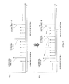
The configuration of G.718-SWB [1] is illustrated in FIGS. 1 and 2 (see, e.g., Non-Patent Literature (hereinafter, referred to as “NPL”) 1).
At an encoding apparatus side illustrated in FIG. 1, the audio signal (hereinafter, referred to as input signal) sampled at 32 kHz is firstly down-sampled to 16 kHz (101). The down-sampled signal is encoded by the G.718 core encoding section (102). The SWB bandwidth extension is performed in MDCT domain. The 32 kHz input signal is transformed to MDCT domain (103) and processed through a tonality estimation section (104). Based on the estimated tonality of the input signal (105), generic mode (106) or sinusoidal mode (108) is used for encoding the first layer of SWB. Higher SWB layers are encoded using additional sinusoids (107 and 109).
The generic mode is used when the input frame signal is not considered to be tonal. In the generic mode, the MDCT coefficients (spectrum) of the WB signal encoded by a G.718 core encoding section are utilized to encode the SWB MDCT coefficients (spectrum). The SWB frequency band (7 to 14 kHz) is split into several subbands, and the most correlated portion is searched for every subband from the encoded and normalized WB MDCT coefficients. Then, a gain of the most correlated portion is calculated in terms of scale such that the amplitude level of SWB subband is reproduced to obtain parametric representation of the high frequency component of SWB signal.
The sinusoidal mode encoding is used in frames that are classified as tonal. In the sinusoidal mode, the SWB signal is generated by adding a finite set of sinusoidal components to the SWB spectrum.
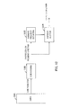
At a decoding apparatus side illustrated in FIG. 2, the G.718 core codec decodes the WB signal at 16 kHz sampling rate (201). The WB signal is post-processed (202), and then up-sampled (203) to 32 kHz sampling rate. The SWB frequency components are reconstructed by SWB bandwidth extension. The SWB bandwidth extension is mainly performed in MDCT domain. Generic mode (204) and sinusoidal mode (205) are used for decoding the first layer of the SWB. Higher SWB layers are decoded using an additional sinusoidal mode (206 and 207). The reconstructed SWB MDCT coefficients are transformed to a time domain (208) followed by post-processing (209), and then added to the WB signal decoded by the G.718 core decoding section to reconstruct the SWB output signal in the time domain.
CITATION LIST Non-Patent Literature
NPL 1: ITU-T Recommendation G.718 Amendment 2, New Annex B on super wideband scalable extension for ITU-T G.718 and corrections to main body fixed-point C-code and description text, March 2010.
SUMMARY OF INVENTION Technical Problem
As it can be seen in G.718-SWB configuration, the input signal SWB bandwidth extension is performed by either sinusoidal mode or generic mode.
For generic encoding mechanism, for example, high frequency components are generated (obtained) by searching for the most correlated portion from the WB spectrum. This type of approach usually suffers from performance problems especially for signals with harmonics. This approach doesn't maintain the harmonic relationship between the low frequency band harmonic components (tonal components) and the replicated high frequency band tonal components at all, which becomes the cause of ambiguous spectra that degrade the auditory quality.
Therefore, in order to suppress the perceived noise (or artifacts), which is generated due to ambiguous spectra or due to disturbance in the replicated high frequency band signal spectrum (high frequency spectrum), it is desirable to maintain the harmonic relationship between the low frequency band signal spectrum (low frequency spectrum) and the high frequency spectrum.
In order to solve this problem, G.718-SWB configuration is equipped with the sinusoidal mode. The sinusoidal mode encodes important tonal components using a sinusoidal wave, and thus it can maintain the harmonic structure well. However, the resultant sound quality is not good enough only by simply encoding the SWB component with artificial tonal signals.
Solution to Problem
An object of the present invention is to improve the performance of encoding a signal with harmonics, which causes the performance problems in the above-described generic mode, and to provide an efficient method for maintaining the harmonic structure of the tonal component between the low frequency spectrum and the replicated high frequency spectrum, while maintaining the fine structure of the spectra. Firstly, a relationship between the low frequency spectrum tonal component and the high frequency spectrum tonal component is obtained by estimating a harmonic frequency value from the WB spectrum. Then, the low frequency spectrum encoded at the encoding apparatus side is decoded, and, according to index information, a portion which is the most correlated with a subband of the high frequency spectrum is copied into the high frequency band with being adjusted in energy levels, thereby replicating the high frequency spectrum. The frequency of the tonal component in the replicated high frequency spectrum is identified or adjusted based on an estimated harmonic frequency value.
The harmonic relationship between the low frequency spectrum tonal components and the replicated high frequency spectrum tonal components can be maintained only when the estimation of a harmonic frequency is accurate. Therefore, in order to improve the accuracy of the estimation, the correction of spectral peaks constituting the tonal components is performed before estimating the harmonic frequency.
Advantageous Effects of Invention
According to the present invention, it is possible to accurately replicate the tonal component in the high frequency spectrum reconstructed by bandwidth extension for an input signal with harmonic structure, and to efficiently obtain good sound quality at low bitrate.
BRIEF DESCRIPTION OF DRAWINGS
FIG. 1 illustrates the configuration of a G.718-SWB encoding apparatus;
FIG. 2 illustrates the configuration of a G.718-SWB decoding apparatus;
FIG. 3 is a block diagram illustrating the configuration of an encoding apparatus according to Embodiment 1 of the present invention;
FIG. 4 is a block diagram illustrating the configuration of a decoding apparatus according to Embodiment 1 of the present invention;
FIG. 5 is a diagram illustrating an approach for correcting the spectral peak detection;
FIG. 6 is a diagram illustrating an example of a harmonic frequency adjustment method;
FIG. 7 is a diagram illustrating another example of a harmonic frequency adjustment method;
FIG. 8 is a block diagram illustrating the configuration of an encoding apparatus according to Embodiment 2 of the present invention;
FIG. 9 is a block diagram illustrating the configuration of a decoding apparatus according to Embodiment 2 of the present invention;
FIG. 10 is a block diagram illustrating the configuration of an encoding apparatus according to Embodiment 3 of the present invention;
FIG. 11 is a block diagram illustrating the configuration of a decoding apparatus according to Embodiment 3 of the present invention;
FIG. 12 is a block diagram illustrating the configuration of a decoding apparatus according to Embodiment 4 of the present invention;
FIG. 13 is a diagram illustrating an example of a harmonic frequency adjustment method for a synthesized low frequency spectrum; and
FIG. 14 is a diagram illustrating an example of an approach for injecting missing harmonics into the synthesized low frequency spectrum.
DESCRIPTION OF EMBODIMENTS
The main principle of the present invention is described in this section using FIGS. 3 to 14. Those skilled in the art will be able to modify or adapt the present invention without deviating from the spirit of the invention.
Embodiment 1
The configuration of a codec according to the present invention is illustrated in FIGS. 3 and 4.
At an encoding apparatus side illustrated in FIG. 3, a sampled input signal is firstly down-sampled (301). The down-sampled low frequency band signal (low frequency signal) is encoded by a core encoding section (302). Core encoding parameters are sent to a multiplexer (307) to form a bitstream. The input signal is transformed to a frequency domain signal using a time-frequency (T/F) transformation section (303), and its high frequency band signal (high frequency signal) is split into a plurality of subbands. The encoding section may be an existing narrow band or wide band audio or speech codec, and one example is G.718. The core encoding section (302) not only performs encoding but also has a local decoding section and a time-frequency transformation section to perform local decoding and time-frequency transformation of the decoded signal (synthesized signal) to supply the synthesized low frequency signal to an energy normalization section (304). The synthesized low frequency signal of the normalized frequency domain is utilized for the bandwidth extension as follows. Firstly, a similarity search section (305) identifies a portion which is the most correlated with each subband of the high frequency signal of the input signal, using the normalized synthesized low frequency signal, and sends the index information as search results to a multiplexing section (307). Next, the information of scale factors between the most correlated portion and each subband of the high frequency signal of the input signal is estimated (306), and encoded scale factor information is sent to the multiplexing section (307).
Finally, the multiplexing section (307) integrates the core encoding parameters, the index information and the scale factor information into a bitstream.
In a decoding apparatus illustrated in FIG. 4, a demultiplexing section (401) unpacks the bitstream to obtain the core encoding parameters, the index information and the scale factor information.
A core decoding section reconstructs synthesized low frequency signals using the core encoding parameters (402). The synthesized low frequency signal is up-sampled (403), and used for bandwidth extension (410).
This bandwidth extension is performed as follows. That is, the synthesized low frequency signal is energy-normalized (404), and a low frequency signal identified according to the index information that identifies a portion which is the most correlated with each subband of the high frequency signal of the input signal derived at the encoding apparatus side is copied into the high frequency band (405), and the energy level is adjusted according to the scale factor information to achieve the same level of the energy level of the high frequency signal of the input signal (406).
Further, a harmonic frequency is estimated from the synthesized low frequency spectrum (407). The estimated harmonic frequency is used to adjust the frequency of the tonal component in the high frequency signal spectrum (408).
The reconstructed high frequency signal is transformed from a frequency domain to a time domain (409), and is added to the up-sampled synthesized low frequency signal to generate an output signal in the time domain.
The detail processing of a harmonic frequency estimation scheme will be described as follows:
  • 1) From the synthesized low frequency signal (LF) spectrum, a portion for estimating a harmonic frequency is selected. The selected portion should have clear harmonic structure so that the harmonic frequency estimated from the selected portion is reliable. Usually, for every harmonic, a clear harmonic structure is observed from 1 to 2 kHz to around a cut-off frequency.
  • 2) The selected portion is split into a multiplicity of blocks with a width near to a human's voice pitch frequency (about 100 to 400 Hz).
  • 3) Spectral peaks, which are the spectrum whose amplitude is the maximum within each block, and spectral peak frequencies, which are the frequencies of those spectral peaks, are searched.
  • 4) Post-processing is performed to the identified spectral peaks in order to avoid errors or to improve the accuracy in the harmonic frequency estimation.
The spectrum illustrated in FIG. 5 is used to describe an example of the post-processing.
Based on the synthesized low frequency signal spectrum, spectral peaks and spectral peak frequencies are calculated. However, a spectral peak with a small amplitude and extremely short spacing of a spectral peak frequency with respect to an adjacent spectral peak is discarded, which avoids estimation errors in calculating a harmonic frequency value.
  • 1) The spacing between the identified spectral peak frequencies is calculated.
  • 2) A harmonic frequency is estimated based on the spacing between the identified spectral peak frequencies. One of the methods for estimating the harmonic frequency is presented as follows:
( Equation 1 ) Spacing peak ( n ) = Pos peak ( n + 1 ) - Pos peak ( n ) , n [ 1 , N - 1 ] Est Harmonic = n = 1 N - 1 Spacing peak ( n ) N - 1 [ 1 ]
where
EstHarmonic is the calculated harmonic frequency;
Spacingpeak is the frequency spacing between the detected peak positions;
N is the number of the detected peak positions;
Pospeak is the position of the detected peak;
The harmonic frequency estimation is also performed according to a method described as follows:
  • 1) In the synthesized low frequency signal (LF) spectrum, in order to estimate a harmonic frequency, a portion having a clear harmonic structure is selected so that the estimated harmonic frequency is reliable. Usually, for every harmonic, a clear harmonic structure can be seen from 1 to 2 kHz to around a cut-off frequency.
  • 2) A spectrum and its frequency having the maximum amplitude (absolute value) are identified within the selected portion of the above-mentioned synthesized low frequency signal (spectrum).
  • 3) A set of spectral peaks having a substantially equal frequency spacing from the spectrum frequency of the spectrum with the maximum amplitude and at which the absolute value of the amplitude exceeds a predetermined threshold is identified. As the predetermined threshold, it is possible to apply, for example, a value twice the standard deviation of the spectral amplitudes contained in the above-mentioned selected portion.
  • 4) The spacing between the above-mentioned spectral peak frequencies is calculated.
  • 5) The harmonic frequency is estimated based on the spacing between the above-mentioned spectral peak frequencies. Also in this case, the method in Equation (1) can be used to estimate the harmonic frequency.
There is a case where the harmonic component in the synthesized low frequency signal spectrum is not well encoded, at a very low bitrate. In this case, there is a possibility that some of the spectral peaks identified may not correspond to the harmonic components of the input signals at all. Therefore, in the calculation of the harmonic frequency, the spacing between spectral peak frequencies which are largely different from the average value should be excluded from the calculation target.
Also, there is a case where not all the harmonic components can be encoded (meaning that some of the harmonic components are missing in the synthesized low frequency signal spectrum) due to the relatively low amplitude of the spectral peak, the bitrate constraints for encoding, or the like. In these cases, the spacing between the spectral peak frequencies extracted at the missing harmonic portion is considered to be twice or a few times the spacing between the spectral peak frequencies extracted at the portion which retains good harmonic structure. In this case, the average value of the extracted values of the spacing between the spectral peak frequencies where the values are included in the predetermined range including the maximum spacing between the spectral peak frequencies is defined as an estimated harmonic frequency value. Thus, it becomes possible to properly replicate the high frequency spectrum. The specific procedure comprises the following steps:
  • 1) The minimum and maximum values of the spacing between the spectral peak frequencies are identified;
( Equation 2 ) Spacing peak ( n ) = Pos peak ( n + 1 ) - Pos peak ( n ) , n [ 1 , N - 1 ] Spacing min = min ( { Spacing peak ( n ) } ) ; Spacing max = max ( { Spacing peak ( n ) } ) ; [ 2 ]
where;
Spacingpeak is the frequency spacing between the detected peak positions;
Spacingmin is the minimum frequency spacing between the detected peak positions;
Spacingmax is the maximum frequency spacing between the detected peak positions;
N is the number of the detected peak positions;
Pospeak is the position of the detected peak;
  • 2) Every spacing between spectral peak frequencies is identified in the range of:
    [k*Spacingmin,Spacingmax ],kε[1,2]  [3]
  • 3) The average value of the identified spacing values between the spectral peak frequencies in the above range is defined as the estimated harmonic frequency value.
Next, one example of harmonic frequency adjustment schemes will be described below.
  • 1) The last encoded spectral peak and its spectral peak frequency are identified in the synthesized low frequency signal (LF) spectrum.
  • 2) The spectral peak and the spectral peak frequency are identified within the high frequency spectrum replicated by bandwidth extension.
  • 3) Using the highest spectral peak frequency as a reference, among spectral peaks of the synthesized low frequency signal spectrum, the spectral peak frequencies are adjusted so that the values of the spacing between the spectral peak frequencies are equal to the estimated value of the spacing between the harmonic frequencies. This processing is illustrated in FIG. 6. As illustrated in FIG. 6, firstly, the highest spectral peak frequency in the synthesized low frequency signal spectrum and the spectral peaks in the replicated high frequency spectrum are identified. Then, the lowest spectral peak frequency in the replicated high frequency spectrum is shifted to the frequency having a spacing of EstHarmonic from the highest spectral peak frequency of the synthesized low frequency signal spectrum. The second lowest spectral peak frequency in the replicated high frequency spectrum is shifted to the frequency having a spacing of EstHarmonic from the above-mentioned shifted lowest spectral peak frequency. The processing is repeated until such an adjustment is completed for every spectral peak frequency of the spectral peak in the replicated high frequency spectrum.
Harmonic frequency adjustment schemes as described below are also possible.
  • 1) The synthesized low frequency signal (LF) spectrum having the highest spectral peak frequency is identified.
  • 2) The spectral peak and the spectral peak frequency within the high frequency (HF) spectrum extended in terms of bandwidth by bandwidth extension are identified.
  • 3) Using the highest spectral peak frequency of the synthesized low frequency signal spectrum as a reference, possible spectral peak frequencies in the HR spectrum are calculated. Each spectral peak in the high frequency spectrum replicated by the bandwidth extension is shifted to a frequency which is the closest to each spectral peak frequency, among the calculated spectral peak frequencies. This processing is illustrated in FIG. 7. As illustrated in FIG. 7, firstly, the synthesized low frequency spectrum having the highest spectral peak frequency and the spectral peaks in the replicated high frequency spectrum are extracted. Then, possible spectral peak frequency in the replicated high frequency spectrum is calculated. The frequency having a spacing of EstHarmonic from the highest spectral peak frequency of the synthesized low frequency signal spectrum is defined as a spectral peak frequency which may be the first spectral peak frequency in the replicated high frequency spectrum. Next, the frequency having a spacing of EstHarmonic from the above-mentioned spectral peak frequency which may be the first spectral peak frequency is defined as a spectral peak frequency which may be the second spectral peak frequency. The processing is repeated as long as the calculation is possible in the high frequency spectrum.
Thereafter, the spectral peak extracted in the replicated high frequency spectrum is shifted to a frequency which is the closest to the spectral peak frequency, among the possible spectral peak frequencies calculated as described above.
There is also a case where the estimated harmonic value EstHarmonic does not correspond to an integer frequency bin. In this case, the spectral peak frequency is selected to be a frequency bin which is the closest to the frequency derived based on EstHarmonic.
There also may be a method of estimating a harmonic frequency in which the previous frame spectrum is utilized to estimate the harmonic frequency, and a method of adjusting the frequencies of tonal components in which the previous frame spectrum is taken into consideration so that the transition between frames is smooth when adjusting the tonal component. It is also possible to adjust the amplitude such that, even when the frequencies of the tonal components are shifted, the energy level of the original spectrum is maintained. All such minor variations are within the scope of the present invention.
The above descriptions are all given as examples, and the ideas of the present invention are not limited by the given examples. Those skilled in the art will be able to modify and adapt the present invention without deviating from the spirit of the invention.
[Effect]
The bandwidth extension method according to the present invention replicates the high frequency spectrum utilizing the synthesized low frequency signal spectrum which is the most correlated with the high frequency spectrum, and shifts the spectral peaks to the estimated harmonic frequencies. Thus, it becomes possible to maintain both the fine structure of the spectrum and the harmonic structure between the low frequency band spectral peaks and the replicated high frequency band spectral peaks.
Embodiment 2
Embodiment 2 of the present invention is illustrated in FIGS. 8 and 9.
The encoding apparatus according to Embodiment 2 is substantially the same as that of Embodiment 1, except harmonic frequency estimation sections (708 and 709) and a harmonic frequency comparison section (710).
The harmonic frequency is estimated separately from synthesized low frequency spectrum (708) and high frequency spectrum (709) of the input signal, and flag information is transmitted based on the comparison result between the estimated values of those (710). As one of the examples, the flag information can be derived as in the following equation:
( Equation 3 ) if Est Harmonic_LF [ Est Harmonic_HF - Threshold , Est Harmonic_HF + Threshold ] Flag = 1 Otherwise Flag = 0 [ 4 ]
where
  • EstHarmonic _ LF is the estimated harmonic frequency from the synthesized low frequency spectrum;
EstHarmonic _ HF is the estimated harmonic frequency from the original high frequency spectrum;
Threshold is a predetermined threshold for the difference between EstHarmonic _ LF and EstHarmonic _ LF
Flag is the flag signal to indicate whether the harmonic adjustment should be applied;
That is, the harmonic frequency estimated from the synthesized low frequency signal spectrum (synthesized low frequency spectrum) EstHarmonic _ LF is compared with the harmonic frequency estimated from the high frequency spectrum of the input signal EstHarmonic _ LF. When the difference between the two values is small enough, it is considered that the estimation from the synthesized low frequency spectrum is accurate enough, and a flag (Flag=1) meaning that it may be used for harmonic frequency adjustment is set. On the other hand, when the difference between the two values is not small, it is considered that the estimated value from the synthesized low frequency spectrum is not accurate, and a flag (Flag=0) meaning that it should not be used for harmonic frequency adjustment is set.
At decoding apparatus side illustrated in FIG. 9, the value of the flag information determines whether or not the harmonic frequency adjustment (810) is applied to the replicated high frequency spectrum. That is, in the case of Flag=1, the decoding apparatus performs harmonic frequency adjustment, whereas in the case of Flag=0, it does not perform harmonic frequency adjustment.
[Effect]
For several input signals, there is a case where the harmonic frequency estimated from the synthesized low frequency spectrum is different from the harmonic frequency of the high frequency spectrum of the input signal. Especially at low bitrate, the harmonic structure of the low frequency spectrum is not well maintained. By sending the flag information, it becomes possible to avoid the adjustment of the tonal component using a wrongly estimated value of the harmonic frequency.
Embodiment 3
Embodiment 3 of the present invention is illustrated in FIGS. 10 and 11.
The encoding apparatus according to Embodiment 3 is substantially the same as that of Embodiment 2, except differential device (910).
The harmonic frequency is estimated separately from the synthesized low frequency spectrum (908) and high frequency spectrum (909) of the input signal. The difference between the two estimated harmonic frequencies (Diff) is calculated (910), and transmitted to the decoding apparatus side.
At decoding apparatus side illustrated in FIG. 11, the difference value (Diff) is added to the estimated value of the harmonic frequency from the synthesized low frequency spectrum (1010), and the newly calculated value of the harmonic frequency is used for the harmonic frequency adjustment in the replicated high frequency spectrum.
Instead of the difference value, the harmonic frequency estimated from the high frequency spectrum of the input signal may also be directly transmitted to the decoding section. Then, the received harmonic frequency value of the high frequency spectrum of the input signal is used to perform the harmonic frequency adjustment. Thus, it becomes unnecessary to estimate the harmonic frequency from the synthesized low frequency spectrum at the decoding apparatus side.
[Effect]
There is a case where, for several signals, the harmonic frequency estimated from the synthesized low frequency spectrum is different from the harmonic frequency of the high frequency spectrum of the input signal. Therefore, by sending the difference value, or the harmonic frequency value derived from the high frequency spectrum of the input signal, it becomes possible to adjust the tonal component of the high frequency spectrum replicated through bandwidth extension by the decoding apparatus at the receiving side more accurately.
Embodiment 4
Embodiment 4 of the present invention is illustrated in FIG. 12.
The encoding apparatus according to Embodiment 4 is the same as any other conventional encoding apparatuses, or is the same as the encoding apparatus in Embodiment 1, 2 or 3.
At decoding apparatus side illustrated in FIG. 12, the harmonic frequency is estimated from the synthesized low frequency spectrum (1103). The estimated value of this harmonic frequency is used for harmonic injection (1104) in the low frequency spectrum.
Especially when the available bitrate is low, there is a case where some of the harmonic components of the low frequency spectrum are hardly encoded, or are not encoded at all. In this case, the estimated harmonic frequency value can be used to inject the missing harmonic components.
This will be illustrated in the FIG. 13. It can be seen, from FIG. 13, that there is a missing harmonic component in the synthesized low frequency (LF) spectrum. Its frequency can be derived using the estimated harmonic frequency value. Further, as for its amplitude, for example, it is possible to use the average value of the amplitudes of other existing spectral peaks or the average value of the amplitudes of the existing spectral peaks neighboring to the missing harmonic component on the frequency axis. The harmonic component generated according to the frequency and amplitude is injected for restoring the missing harmonic component.
Another approach for injecting the missing harmonic component will be described as follows:
  • 1. The harmonic frequency is estimated using the encoded LF spectrum (1103).
  • 1.1 The harmonic frequency is estimated using spacing between spectral peak frequencies identified in the encoded low frequency spectrum.
  • 1.2 The values of spacing between the spectral peak frequencies, which are derived from the missing harmonic portion, become twice or a few times of values of the spacing between the spectral peak frequencies, which are derived from a portion which has a good harmonic structure. Such values of the spacing between the spectral peak frequencies are grouped into different categories, and the average spacing value between the spectral peak frequencies is estimated for each of the categories. The detail thereof will be described as follows:
  • a. The minimum value and the maximum value of the spacing value between the spectral peak frequencies are identified.
( Equation 4 ) Spacing peak ( n ) = Pos peak ( n + 1 ) - Pos peak ( n ) , n [ 1 , N - 1 ] Spacing min = min ( { Spacing peak ( n ) } ) ; Spacing max = max ( { Spacing peak ( n ) } ) ; [ 5 ]
where; I
Spacingpeak is the frequency spacing between the detected peak positions;
Spacingmin is the minimum frequency spacing between the detected peak positions;
Spacingmax is the maximum frequency spacing between the detected peak positions;
N is the number of the detected peak positions;
Pospeak is the position of the detected peak;
  • b. Every spacing value is identified in the range of:
    r t=[Spacingmin ,k*Spacingmin)
    r 2 =[k*Spacingmin,Spacingmax],1<k≦2  [6]
  • c. The average values of the spacing values identified in the above ranges are calculated as the estimated harmonic frequency values.
( Equation 5 ) Est Harmonic LF 1 = Spacing peak ( n ) N 1 , Spacing peak ( n ) r 1 Est Harmonic LF 2 = Spacing peak ( n ) N 2 , Spacing peak ( n ) r 2 [ 7 ]
where
EstHarmonic LF1 , EstHarmonic LF2 are the estimated harmonic frequencies
N1 is the number of the detected peak positions belonging to r1
N2 is the number of the detected peak positions belonging to r2
  • 2. Using the estimated harmonic frequency values, the missing harmonic components are injected.
  • 2.1 The selected LF spectrum is split into several regions.
  • 2.2 The missing harmonics are identified by utilizing region information and the estimated frequencies.
For example, assume that the selected LF spectrum is split into three regions r1, r2, and r3.
Based on the region information, the harmonics are identified and injected.
Due to the signal characteristics for harmonics, the spectral gap between harmonics is EstHarmonic LF1 in r1 and r2 regions, and is EstHarmonic LF2 in r3 region. This information can be used for extending the LF spectrum. This is illustrated further in FIG. 14. It can be seen, from FIG. 14, that there is a missing harmonic component in the domain r2 of the LF spectrum. This frequency can be derived using the estimated harmonic frequency value EstHarmonic LF1 .
Similarly, EstHarmonic LF2 is used for tracking and injecting the missing harmonic in region r3.
Further, as for its amplitude, it is possible to use the average value of the amplitudes of all the harmonic components which are not missing or the average value of the amplitudes of the harmonic components preceding and following the missing harmonic component. Alternatively, as for the amplitude, a spectral peak with the minimum amplitude in the WB spectrum may be used. The harmonic component generated using the frequency and amplitude is injected into the LF spectrum for restoring the missing harmonic component.
[Effect]
There is a case where the synthesized low frequency spectrum is not maintained for several signals. Especially at low bitrate, there is a possibility that several harmonic components may be missing. By injecting the missing harmonic components in the LF spectrum, it becomes possible not only to extend the LF, but also improve the harmonic characteristics of the reconstructed harmonics. This can suppress the auditory influence due to missing harmonics to further improve the sound quality.
The disclosure of Japanese Patent Application No. 2013-122985 filed on Jun. 11, 2013, including the specification, drawings and abstract, is incorporated herein by reference in its entirety.
INDUSTRIAL APPLICABILITY
The encoding apparatus, decoding apparatus and encoding and decoding methods according to the present invention are applicable to a wireless communication terminal apparatus, base station apparatus in a mobile communication system, tele-conference terminal apparatus, video conference terminal apparatus, and voice over internet protocol (VOIP) terminal apparatus.

Claims (7)

The invention claimed is:
1. An audio signal decoding apparatus, comprising:
a demultiplexer that demultiplexes low-band encoding parameters, index information, and scale factor information from encoded information transmitted from an encoding apparatus that encodes an audio signal;
a low-band decoder that decodes the low-band encoding parameters to obtain a synthesized low frequency spectrum;
a spectrum replicator that replicates a high frequency subband spectrum based on the index information using the synthesized low frequency spectrum;
a spectrum envelope adjuster that adjusts an amplitude of the replicated high frequency subband spectrum using the scale factor information,
a harmonic frequency estimator that estimates a frequency of a harmonic component in the synthesized low frequency spectrum;
a harmonic frequency adjuster that adjusts a frequency of a harmonic component in the high frequency subband spectrum using the estimated harmonic frequency spectrum; and
an output that generates an output signal using the synthesized low frequency spectrum and the high frequency subband spectrum.
2. The audio signal decoding apparatus according to claim 1,
wherein the harmonic frequency estimator comprises:
a splitter that splits a preselected portion of the synthesized low frequency spectrum into a predetermined number of blocks;
a spectral peak identifier that determines a spectrum (spectral peak) having a maximum amplitude in each block and a frequency of the spectral peak;
a spacing calculator that calculates spacing between the identified spectral peak frequencies; and
a harmonic frequency calculator that calculates the harmonic frequency using the spacing between the identified spectral peak frequencies.
3. The audio signal decoding apparatus according to claim 1,
wherein the harmonic frequency estimator comprises:
a spectral peak identifier that identifies a spectrum having a maximum absolute value of an amplitude at the preselected portion of the synthesized low frequency spectrum and spectra which are positioned at substantially regular spacing from the spectrum on a frequency axis and which have an amplitude whose absolute value is equal to or larger than a predetermined threshold;
a spacing calculator that calculates the spacing between frequencies of the identified spectral peaks; and
a harmonic frequency calculator that calculates the harmonic frequency using the spacing between the frequencies of the identified spectra.
4. The audio signal decoding apparatus according to claim 2,
wherein the adjuster comprises:
a low frequency spectral peak identifier that identifies a highest frequency of spectral peaks in the synthesized low frequency spectrum;
a high frequency spectral peak identifier that identifies a plurality of spectral peak frequencies in the replicated high frequency subband spectrum; and
a second adjuster that uses, as a reference, the highest frequency of the spectral peaks in the synthesized low frequency spectrum for adjusting the plurality of spectral peak frequencies so that the spacing between the plurality of spectral peak frequencies is equal to the estimated harmonic frequency.
5. An audio signal encoding apparatus, comprising:
a low-band encoder that encodes a low frequency audio signal and outputs synthesized low frequency spectrum, and generates low-band parameters and outputs the parameters;
a subband splitter that transforms a high frequency audio signal to a frequency spectrum and split a high frequency spectrum into a plurality of high frequency subbands, the high frequency spectrum being obtained using time-frequency transformed an input audio signal;
a searcher that identifies the most correlated portion from the synthesized low frequency spectrum for each of the high frequency subbands and outputs the identification result as index information;
a scale factor estimator that estimates an energy scale factor between each of the high frequency subbands and the most correlated portion identified from the synthesized low frequency spectrum and outputs the scale factor as scale factor information;
a harmonic frequency estimator that estimates and outputs a harmonic frequency of the synthesized low frequency spectrum and a harmonic frequency of the transformed input audio signal; and
a multiplexer that multiplexes the low-band parameter, the index information, and the scale factor information.
6. An audio signal decoding method, comprising:
demultiplexing low-band encoding parameters, index information, and scale factor information from encoded information transmitted from an encoding apparatus that encodes an audio signal;
decoding the low-band encoding parameters to obtain a synthesized low frequency spectrum;
replicating a high frequency subband spectrum based on the index information using the synthesized low frequency spectrum;
adjusting an amplitude of the replicated high frequency subband spectrum using the scale factor information,
estimating a frequency of a harmonic component in the synthesized low frequency spectrum;
adjusting a frequency of a harmonic component in the high frequency subband spectrum using the estimated harmonic frequency spectrum; and
generating an output signal using the synthesized low frequency spectrum and the high frequency subband spectrum.
7. An audio signal encoding method, comprising:
encoding a low frequency audio signal and outputs synthesized low frequency spectrum, and generates low-band parameters and outputs the parameters;
transforming a high frequency audio signal to a frequency spectrum;
splitting a high frequency spectrum into a plurality of high frequency subbands, the high frequency spectrum being obtained using time-frequency transformed an input audio signal;
identifying the most correlated portion from the synthesized low frequency spectrum for each of the high frequency subbands;
outputting the identification result as index information;
estimating an energy scale factor between each of the high frequency subbands and the most correlated portion identified from the synthesized low frequency spectrum and outputs the scale factor as scale factor information;
estimating a harmonic frequency of the synthesized low frequency spectrum and a harmonic frequency of the transformed input audio signal; and
multiplexing the low-band parameter, the index information, and the scale factor information.
US14/894,062 2013-06-11 2014-06-10 Device and method for bandwidth extension for audio signals Active US9489959B2 (en)

Applications Claiming Priority (3)

Application Number Priority Date Filing Date Title
JP2013-122985 2013-06-11
JP2013122985 2013-06-11
PCT/JP2014/003103 WO2014199632A1 (en) 2013-06-11 2014-06-10 Device and method for bandwidth extension for acoustic signals

Related Parent Applications (1)

Application Number Title Priority Date Filing Date
PCT/JP2014/003103 A-371-Of-International WO2014199632A1 (en) 2013-06-11 2014-06-10 Device and method for bandwidth extension for acoustic signals

Related Child Applications (1)

Application Number Title Priority Date Filing Date
US15/286,030 Continuation US9747908B2 (en) 2013-06-11 2016-10-05 Device and method for bandwidth extension for audio signals

Publications (2)

Publication Number Publication Date
US20160111103A1 US20160111103A1 (en) 2016-04-21
US9489959B2 true US9489959B2 (en) 2016-11-08

Family

ID=52021944

Family Applications (4)

Application Number Title Priority Date Filing Date
US14/894,062 Active US9489959B2 (en) 2013-06-11 2014-06-10 Device and method for bandwidth extension for audio signals
US15/286,030 Active US9747908B2 (en) 2013-06-11 2016-10-05 Device and method for bandwidth extension for audio signals
US15/659,023 Active US10157622B2 (en) 2013-06-11 2017-07-25 Device and method for bandwidth extension for audio signals
US16/219,656 Active US10522161B2 (en) 2013-06-11 2018-12-13 Device and method for bandwidth extension for audio signals

Family Applications After (3)

Application Number Title Priority Date Filing Date
US15/286,030 Active US9747908B2 (en) 2013-06-11 2016-10-05 Device and method for bandwidth extension for audio signals
US15/659,023 Active US10157622B2 (en) 2013-06-11 2017-07-25 Device and method for bandwidth extension for audio signals
US16/219,656 Active US10522161B2 (en) 2013-06-11 2018-12-13 Device and method for bandwidth extension for audio signals

Country Status (11)

Country Link
US (4) US9489959B2 (en)
EP (2) EP3010018B1 (en)
JP (4) JP6407150B2 (en)
KR (1) KR102158896B1 (en)
CN (2) CN105408957B (en)
BR (2) BR122020016403B1 (en)
ES (1) ES2836194T3 (en)
MX (1) MX353240B (en)
PT (1) PT3010018T (en)
RU (2) RU2688247C2 (en)
WO (1) WO2014199632A1 (en)

Cited By (3)

* Cited by examiner, † Cited by third party
Publication number Priority date Publication date Assignee Title
US20170270944A1 (en) * 2013-01-29 2017-09-21 Huawei Technologies Co.,Ltd. Method for predicting high frequency band signal, encoding device, and decoding device
US20170323649A1 (en) * 2013-06-11 2017-11-09 Panasonic Intellectual Property Corporation Of America Device and method for bandwidth extension for audio signals
US10453469B2 (en) * 2017-04-28 2019-10-22 Nxp B.V. Signal processor

Families Citing this family (20)

* Cited by examiner, † Cited by third party
Publication number Priority date Publication date Assignee Title
CN103516440B (en) * 2012-06-29 2015-07-08 华为技术有限公司 Audio signal processing method and encoding device
WO2015151451A1 (en) * 2014-03-31 2015-10-08 パナソニック インテレクチュアル プロパティ コーポレーション オブ アメリカ Encoder, decoder, encoding method, decoding method, and program
US9697843B2 (en) * 2014-04-30 2017-07-04 Qualcomm Incorporated High band excitation signal generation
EP2980795A1 (en) 2014-07-28 2016-02-03 Fraunhofer-Gesellschaft zur Förderung der angewandten Forschung e.V. Audio encoding and decoding using a frequency domain processor, a time domain processor and a cross processor for initialization of the time domain processor
EP2980794A1 (en) 2014-07-28 2016-02-03 Fraunhofer-Gesellschaft zur Förderung der angewandten Forschung e.V. Audio encoder and decoder using a frequency domain processor and a time domain processor
TWI758146B (en) 2015-03-13 2022-03-11 瑞典商杜比國際公司 Decoding audio bitstreams with enhanced spectral band replication metadata in at least one fill element
CN105280189B (en) * 2015-09-16 2019-01-08 深圳广晟信源技术有限公司 The method and apparatus that bandwidth extension encoding and decoding medium-high frequency generate
EP3182411A1 (en) * 2015-12-14 2017-06-21 Fraunhofer-Gesellschaft zur Förderung der angewandten Forschung e.V. Apparatus and method for processing an encoded audio signal
US10346126B2 (en) 2016-09-19 2019-07-09 Qualcomm Incorporated User preference selection for audio encoding
JP6769299B2 (en) * 2016-12-27 2020-10-14 富士通株式会社 Audio coding device and audio coding method
US10896684B2 (en) 2017-07-28 2021-01-19 Fujitsu Limited Audio encoding apparatus and audio encoding method
CN111386568B (en) * 2017-10-27 2023-10-13 弗劳恩霍夫应用研究促进协会 Apparatus, method, or computer readable storage medium for generating bandwidth enhanced audio signals using a neural network processor
CN108630212B (en) * 2018-04-03 2021-05-07 湖南商学院 Perception reconstruction method and device for high-frequency excitation signal in non-blind bandwidth extension
CN110660409A (en) * 2018-06-29 2020-01-07 华为技术有限公司 Method and device for spreading spectrum
WO2020041497A1 (en) * 2018-08-21 2020-02-27 2Hz, Inc. Speech enhancement and noise suppression systems and methods
CN109243485B (en) * 2018-09-13 2021-08-13 广州酷狗计算机科技有限公司 Method and apparatus for recovering high frequency signal
JP6693551B1 (en) * 2018-11-30 2020-05-13 株式会社ソシオネクスト Signal processing device and signal processing method
CN113192517B (en) * 2020-01-13 2024-04-26 华为技术有限公司 Audio encoding and decoding method and audio encoding and decoding equipment
CN113362837B (en) * 2021-07-28 2024-05-14 腾讯音乐娱乐科技(深圳)有限公司 Audio signal processing method, equipment and storage medium
CN114550732B (en) * 2022-04-15 2022-07-08 腾讯科技(深圳)有限公司 Coding and decoding method and related device for high-frequency audio signal

Citations (14)

* Cited by examiner, † Cited by third party
Publication number Priority date Publication date Assignee Title
JP2003108197A (en) 2001-07-13 2003-04-11 Matsushita Electric Ind Co Ltd Audio signal decoding device and audio signal encoding device
US20040028244A1 (en) 2001-07-13 2004-02-12 Mineo Tsushima Audio signal decoding device and audio signal encoding device
US20070071116A1 (en) 2003-10-23 2007-03-29 Matsushita Electric Industrial Co., Ltd Spectrum coding apparatus, spectrum decoding apparatus, acoustic signal transmission apparatus, acoustic signal reception apparatus and methods thereof
US20080052066A1 (en) * 2004-11-05 2008-02-28 Matsushita Electric Industrial Co., Ltd. Encoder, Decoder, Encoding Method, and Decoding Method
US20100063803A1 (en) * 2008-09-06 2010-03-11 GH Innovation, Inc. Spectrum Harmonic/Noise Sharpness Control
US20100063827A1 (en) * 2008-09-06 2010-03-11 GH Innovation, Inc. Selective Bandwidth Extension
US20100063802A1 (en) * 2008-09-06 2010-03-11 Huawei Technologies Co., Ltd. Adaptive Frequency Prediction
WO2010036061A2 (en) 2008-09-25 2010-04-01 Lg Electronics Inc. An apparatus for processing an audio signal and method thereof
WO2010081892A2 (en) 2009-01-16 2010-07-22 Dolby Sweden Ab Cross product enhanced harmonic transposition
US20110194598A1 (en) 2008-12-10 2011-08-11 Huawei Technologies Co., Ltd. Methods, Apparatuses and System for Encoding and Decoding Signal
WO2012016110A2 (en) 2010-07-30 2012-02-02 Qualcomm Incorporated Systems, methods, apparatus, and computer-readable media for coding of harmonic signals
US20130018660A1 (en) 2011-07-13 2013-01-17 Huawei Technologies Co., Ltd. Audio signal coding and decoding method and device
US20130030796A1 (en) * 2010-01-14 2013-01-31 Panasonic Corporation Audio encoding apparatus and audio encoding method
US20140200901A1 (en) * 2011-09-09 2014-07-17 Panasonic Corporation Encoding device, decoding device, encoding method and decoding method

Family Cites Families (21)

* Cited by examiner, † Cited by third party
Publication number Priority date Publication date Assignee Title
JP3246715B2 (en) * 1996-07-01 2002-01-15 松下電器産業株式会社 Audio signal compression method and audio signal compression device
EP2071565B1 (en) * 2003-09-16 2011-05-04 Panasonic Corporation Coding apparatus and decoding apparatus
JP4741476B2 (en) * 2004-04-23 2011-08-03 パナソニック株式会社 Encoder
CN100559138C (en) * 2004-05-14 2009-11-11 松下电器产业株式会社 Code device, decoding device and coding/decoding method
JP4899359B2 (en) * 2005-07-11 2012-03-21 ソニー株式会社 Signal encoding apparatus and method, signal decoding apparatus and method, program, and recording medium
US20070299655A1 (en) * 2006-06-22 2007-12-27 Nokia Corporation Method, Apparatus and Computer Program Product for Providing Low Frequency Expansion of Speech
EP2101322B1 (en) * 2006-12-15 2018-02-21 III Holdings 12, LLC Encoding device, decoding device, and method thereof
KR101238239B1 (en) 2007-11-06 2013-03-04 노키아 코포레이션 An encoder
CN101471072B (en) * 2007-12-27 2012-01-25 华为技术有限公司 High-frequency reconstruction method, encoding device and decoding module
US9037474B2 (en) * 2008-09-06 2015-05-19 Huawei Technologies Co., Ltd. Method for classifying audio signal into fast signal or slow signal
MX2011008685A (en) * 2009-02-26 2011-09-06 Panasonic Corp Encoder, decoder, and method therefor.
CN101521014B (en) * 2009-04-08 2011-09-14 武汉大学 Audio bandwidth expansion coding and decoding devices
CO6440537A2 (en) * 2009-04-09 2012-05-15 Fraunhofer Ges Forschung APPARATUS AND METHOD TO GENERATE A SYNTHESIS AUDIO SIGNAL AND TO CODIFY AN AUDIO SIGNAL
CN102598123B (en) * 2009-10-23 2015-07-22 松下电器(美国)知识产权公司 Encoding apparatus, decoding apparatus and methods thereof
RU2582061C2 (en) * 2010-06-09 2016-04-20 Панасоник Интеллекчуал Проперти Корпорэйшн оф Америка Bandwidth extension method, bandwidth extension apparatus, program, integrated circuit and audio decoding apparatus
PL2596497T3 (en) * 2010-07-19 2014-10-31 Dolby Int Ab Processing of audio signals during high frequency reconstruction
JP5707842B2 (en) * 2010-10-15 2015-04-30 ソニー株式会社 Encoding apparatus and method, decoding apparatus and method, and program
DK4020466T3 (en) * 2011-02-18 2023-06-26 Ntt Docomo Inc SPEECH CODES AND SPEECH CODING PROCEDURE
CN102800317B (en) * 2011-05-25 2014-09-17 华为技术有限公司 Signal classification method and equipment, and encoding and decoding methods and equipment
JP2013122985A (en) 2011-12-12 2013-06-20 Toshiba Corp Semiconductor memory device
JP6407150B2 (en) 2013-06-11 2018-10-17 フラウンホッファー−ゲゼルシャフト ツァ フェルダールング デァ アンゲヴァンテン フォアシュンク エー.ファオ Apparatus and method for expanding bandwidth of acoustic signal

Patent Citations (34)

* Cited by examiner, † Cited by third party
Publication number Priority date Publication date Assignee Title
US7260541B2 (en) 2001-07-13 2007-08-21 Matsushita Electric Industrial Co., Ltd. Audio signal decoding device and audio signal encoding device
US20040028244A1 (en) 2001-07-13 2004-02-12 Mineo Tsushima Audio signal decoding device and audio signal encoding device
JP2003108197A (en) 2001-07-13 2003-04-11 Matsushita Electric Ind Co Ltd Audio signal decoding device and audio signal encoding device
JP2011100159A (en) 2003-10-23 2011-05-19 Panasonic Corp Spectrum coding apparatus, spectrum decoding apparatus, acoustic signal transmission apparatus, acoustic signal reception apparatus and methods thereof
US20110196674A1 (en) 2003-10-23 2011-08-11 Panasonic Corporation Spectrum coding apparatus, spectrum decoding apparatus, acoustic signal transmission apparatus, acoustic signal reception apparatus and methods thereof
US8275061B2 (en) 2003-10-23 2012-09-25 Panasonic Corporation Spectrum coding apparatus, spectrum decoding apparatus, acoustic signal transmission apparatus, acoustic signal reception apparatus and methods thereof
US20110194635A1 (en) 2003-10-23 2011-08-11 Panasonic Corporation Spectrum coding apparatus, spectrum decoding apparatus, acoustic signal transmission apparatus, acoustic signal reception apparatus and methods thereof
US20070071116A1 (en) 2003-10-23 2007-03-29 Matsushita Electric Industrial Co., Ltd Spectrum coding apparatus, spectrum decoding apparatus, acoustic signal transmission apparatus, acoustic signal reception apparatus and methods thereof
US8315322B2 (en) 2003-10-23 2012-11-20 Panasonic Corporation Spectrum coding apparatus, spectrum decoding apparatus, acoustic signal transmission apparatus, acoustic signal reception apparatus and methods thereof
US20110196686A1 (en) 2003-10-23 2011-08-11 Panasonic Corporation Spectrum coding apparatus, spectrum decoding apparatus, acoustic signal transmission apparatus, acoustic signal reception apparatus and methods thereof
US8208570B2 (en) 2003-10-23 2012-06-26 Panasonic Corporation Spectrum coding apparatus, spectrum decoding apparatus, acoustic signal transmission apparatus, acoustic signal reception apparatus and methods thereof
US7949057B2 (en) 2003-10-23 2011-05-24 Panasonic Corporation Spectrum coding apparatus, spectrum decoding apparatus, acoustic signal transmission apparatus, acoustic signal reception apparatus and methods thereof
US20080052066A1 (en) * 2004-11-05 2008-02-28 Matsushita Electric Industrial Co., Ltd. Encoder, Decoder, Encoding Method, and Decoding Method
US7769584B2 (en) * 2004-11-05 2010-08-03 Panasonic Corporation Encoder, decoder, encoding method, and decoding method
US20100063802A1 (en) * 2008-09-06 2010-03-11 Huawei Technologies Co., Ltd. Adaptive Frequency Prediction
US8515747B2 (en) * 2008-09-06 2013-08-20 Huawei Technologies Co., Ltd. Spectrum harmonic/noise sharpness control
US8532998B2 (en) * 2008-09-06 2013-09-10 Huawei Technologies Co., Ltd. Selective bandwidth extension for encoding/decoding audio/speech signal
US20100063827A1 (en) * 2008-09-06 2010-03-11 GH Innovation, Inc. Selective Bandwidth Extension
US20100063803A1 (en) * 2008-09-06 2010-03-11 GH Innovation, Inc. Spectrum Harmonic/Noise Sharpness Control
WO2010036061A2 (en) 2008-09-25 2010-04-01 Lg Electronics Inc. An apparatus for processing an audio signal and method thereof
US8831958B2 (en) 2008-09-25 2014-09-09 Lg Electronics Inc. Method and an apparatus for a bandwidth extension using different schemes
US20100114583A1 (en) 2008-09-25 2010-05-06 Lg Electronics Inc. Apparatus for processing an audio signal and method thereof
US8135593B2 (en) 2008-12-10 2012-03-13 Huawei Technologies Co., Ltd. Methods, apparatuses and system for encoding and decoding signal
US20110194598A1 (en) 2008-12-10 2011-08-11 Huawei Technologies Co., Ltd. Methods, Apparatuses and System for Encoding and Decoding Signal
WO2010081892A2 (en) 2009-01-16 2010-07-22 Dolby Sweden Ab Cross product enhanced harmonic transposition
US20110305352A1 (en) 2009-01-16 2011-12-15 Dolby International Ab Cross Product Enhanced Harmonic Transposition
US8818541B2 (en) 2009-01-16 2014-08-26 Dolby International Ab Cross product enhanced harmonic transposition
US20130030796A1 (en) * 2010-01-14 2013-01-31 Panasonic Corporation Audio encoding apparatus and audio encoding method
US20120029923A1 (en) 2010-07-30 2012-02-02 Qualcomm Incorporated Systems, methods, apparatus, and computer-readable media for coding of harmonic signals
WO2012016110A2 (en) 2010-07-30 2012-02-02 Qualcomm Incorporated Systems, methods, apparatus, and computer-readable media for coding of harmonic signals
US8924222B2 (en) 2010-07-30 2014-12-30 Qualcomm Incorporated Systems, methods, apparatus, and computer-readable media for coding of harmonic signals
US20130018660A1 (en) 2011-07-13 2013-01-17 Huawei Technologies Co., Ltd. Audio signal coding and decoding method and device
US9105263B2 (en) 2011-07-13 2015-08-11 Huawei Technologies Co., Ltd. Audio signal coding and decoding method and device
US20140200901A1 (en) * 2011-09-09 2014-07-17 Panasonic Corporation Encoding device, decoding device, encoding method and decoding method

Non-Patent Citations (4)

* Cited by examiner, † Cited by third party
Title
International Search Report, mailed Jul. 22, 2014, in corresponding International Application No. PCT/JP2014/003103.
ITU-T Recommendation G.718 (2008), Amendment 2: New Annex B on superwideband scalable extension for ITU-T G.718 and corrections to main body fixed-point C-code and description text, "Frame error robust narrow-band and wideband embedded variable bit-rate coding of speech and audio from 8-32 kbits/s", (Mar. 2010).
Miao, Lei; Liu, Zexin; Hu, Chen; Eksler, Vaclav; Ragot, Stephane; Lamblin, Claude; Kovesi, Balazs; Sung, Jongmo; Fukui, Masahiro; Sasaki, Shigeaki; Hiwasaki, Yusuke "G.711.1 Annex D and G.722 Annex B-New ITU-T superwideband codecs", Acoustics, Speech and Signal Processing (ICASSP), 2011 IEEE International Conference on, on pp. 5232-5235. *
Y. Hiwasaki and H. Ohmuro, "ITU-T G.711.1: extending G.711 to higher-quality wideband speech," in IEEE Communications Magazine, vol. 47, No. 10, pp. 110-116, Oct. 2009. *

Cited By (8)

* Cited by examiner, † Cited by third party
Publication number Priority date Publication date Assignee Title
US20170270944A1 (en) * 2013-01-29 2017-09-21 Huawei Technologies Co.,Ltd. Method for predicting high frequency band signal, encoding device, and decoding device
US10089997B2 (en) * 2013-01-29 2018-10-02 Huawei Technologies Co.,Ltd. Method for predicting high frequency band signal, encoding device, and decoding device
US10636432B2 (en) 2013-01-29 2020-04-28 Huawei Technologies Co., Ltd. Method for predicting high frequency band signal, encoding device, and decoding device
US20170323649A1 (en) * 2013-06-11 2017-11-09 Panasonic Intellectual Property Corporation Of America Device and method for bandwidth extension for audio signals
US10157622B2 (en) * 2013-06-11 2018-12-18 Fraunhofer-Gesellschaft Zur Foerderung Der Angewandten Forschung E.V. Device and method for bandwidth extension for audio signals
US20190122679A1 (en) * 2013-06-11 2019-04-25 Fraunhofer-Gesellschaft Zur Foerderung Der Angewandten Forschung E.V. Device and method for bandwidth extension for audio signals
US10522161B2 (en) * 2013-06-11 2019-12-31 Fraunhofer-Gesellschaft Zur Foerderung Der Angewandten Forschung E.V. Device and method for bandwidth extension for audio signals
US10453469B2 (en) * 2017-04-28 2019-10-22 Nxp B.V. Signal processor

Also Published As

Publication number Publication date
US20170323649A1 (en) 2017-11-09
JP6407150B2 (en) 2018-10-17
JPWO2014199632A1 (en) 2017-02-23
US9747908B2 (en) 2017-08-29
PT3010018T (en) 2020-11-13
ES2836194T3 (en) 2021-06-24
RU2018121035A (en) 2019-03-05
US20170025130A1 (en) 2017-01-26
BR112015029574A2 (en) 2017-07-25
BR112015029574B1 (en) 2021-12-21
BR122020016403B1 (en) 2022-09-06
CN111477245A (en) 2020-07-31
US10522161B2 (en) 2019-12-31
KR20160018497A (en) 2016-02-17
RU2015151169A (en) 2017-06-05
MX353240B (en) 2018-01-05
KR102158896B1 (en) 2020-09-22
EP3010018A4 (en) 2016-06-15
RU2658892C2 (en) 2018-06-25
JP7330934B2 (en) 2023-08-22
US20160111103A1 (en) 2016-04-21
JP2019008316A (en) 2019-01-17
WO2014199632A1 (en) 2014-12-18
RU2018121035A3 (en) 2019-03-05
RU2688247C2 (en) 2019-05-21
EP3010018A1 (en) 2016-04-20
CN105408957B (en) 2020-02-21
US20190122679A1 (en) 2019-04-25
JP6773737B2 (en) 2020-10-21
RU2015151169A3 (en) 2018-03-02
EP3731226A1 (en) 2020-10-28
CN105408957A (en) 2016-03-16
MX2015016109A (en) 2016-10-26
JP2019008317A (en) 2019-01-17
JP2021002069A (en) 2021-01-07
EP3010018B1 (en) 2020-08-12
US10157622B2 (en) 2018-12-18

Similar Documents

Publication Publication Date Title
US10157622B2 (en) Device and method for bandwidth extension for audio signals
US8417515B2 (en) Encoding device, decoding device, and method thereof
US9406307B2 (en) Method and apparatus for polyphonic audio signal prediction in coding and networking systems
JP5418930B2 (en) Speech decoding method and speech decoder
US9830920B2 (en) Method and apparatus for polyphonic audio signal prediction in coding and networking systems
US10818304B2 (en) Phase coherence control for harmonic signals in perceptual audio codecs
US20140114651A1 (en) Device and method for execution of huffman coding
KR20080049085A (en) Audio encoding device and audio encoding method
US20090125300A1 (en) Scalable encoding apparatus, scalable decoding apparatus, and methods thereof
MX2013010879A (en) Encoding apparatus and method, and program.
US9117461B2 (en) Coding device, decoding device, coding method, and decoding method for audio signals
KR20160138373A (en) Encoder, decoder, encoding method, decoding method, and program
US11688408B2 (en) Perceptual audio coding with adaptive non-uniform time/frequency tiling using subband merging and the time domain aliasing reduction

Legal Events

Date Code Title Description
AS Assignment

Owner name: PANASONIC INTELLECTUAL PROPERTY CORPORATION OF AME

Free format text: ASSIGNMENT OF ASSIGNORS INTEREST;ASSIGNORS:NAGISETTY, SRIKANTH;LIU, ZONGXIAN;REEL/FRAME:037680/0721

Effective date: 20151013

STCF Information on status: patent grant

Free format text: PATENTED CASE

CC Certificate of correction
AS Assignment

Owner name: FRAUNHOFER-GESELLSCHAFT ZUR FOERDERUNG DER ANGEWAN

Free format text: ASSIGNMENT OF ASSIGNORS INTEREST;ASSIGNOR:PANASONIC INTELLECTUAL PROPERTY CORPORATION OF AMERICA;REEL/FRAME:043971/0349

Effective date: 20170928

MAFP Maintenance fee payment

Free format text: PAYMENT OF MAINTENANCE FEE, 4TH YEAR, LARGE ENTITY (ORIGINAL EVENT CODE: M1551); ENTITY STATUS OF PATENT OWNER: LARGE ENTITY

Year of fee payment: 4

MAFP Maintenance fee payment

Free format text: PAYMENT OF MAINTENANCE FEE, 8TH YEAR, LARGE ENTITY (ORIGINAL EVENT CODE: M1552); ENTITY STATUS OF PATENT OWNER: LARGE ENTITY

Year of fee payment: 8