US9482699B2 - Method and apparatus for monitoring high voltage bushings safely - Google Patents
Method and apparatus for monitoring high voltage bushings safely Download PDFInfo
- Publication number
- US9482699B2 US9482699B2 US14/303,591 US201414303591A US9482699B2 US 9482699 B2 US9482699 B2 US 9482699B2 US 201414303591 A US201414303591 A US 201414303591A US 9482699 B2 US9482699 B2 US 9482699B2
- Authority
- US
- United States
- Prior art keywords
- bushing
- circuitry
- coupler
- voltage
- signals
- Prior art date
- Legal status (The legal status is an assumption and is not a legal conclusion. Google has not performed a legal analysis and makes no representation as to the accuracy of the status listed.)
- Active, expires
Links
Images


Classifications
-
- G—PHYSICS
- G01—MEASURING; TESTING
- G01R—MEASURING ELECTRIC VARIABLES; MEASURING MAGNETIC VARIABLES
- G01R15/00—Details of measuring arrangements of the types provided for in groups G01R17/00 - G01R29/00, G01R33/00 - G01R33/26 or G01R35/00
- G01R15/14—Adaptations providing voltage or current isolation, e.g. for high-voltage or high-current networks
- G01R15/16—Adaptations providing voltage or current isolation, e.g. for high-voltage or high-current networks using capacitive devices
-
- G—PHYSICS
- G01—MEASURING; TESTING
- G01R—MEASURING ELECTRIC VARIABLES; MEASURING MAGNETIC VARIABLES
- G01R1/00—Details of instruments or arrangements of the types included in groups G01R5/00 - G01R13/00 and G01R31/00
- G01R1/36—Overload-protection arrangements or circuits for electric measuring instruments
-
- G—PHYSICS
- G01—MEASURING; TESTING
- G01R—MEASURING ELECTRIC VARIABLES; MEASURING MAGNETIC VARIABLES
- G01R15/00—Details of measuring arrangements of the types provided for in groups G01R17/00 - G01R29/00, G01R33/00 - G01R33/26 or G01R35/00
- G01R15/14—Adaptations providing voltage or current isolation, e.g. for high-voltage or high-current networks
-
- G—PHYSICS
- G01—MEASURING; TESTING
- G01R—MEASURING ELECTRIC VARIABLES; MEASURING MAGNETIC VARIABLES
- G01R19/00—Arrangements for measuring currents or voltages or for indicating presence or sign thereof
- G01R19/0084—Arrangements for measuring currents or voltages or for indicating presence or sign thereof measuring voltage only
-
- G—PHYSICS
- G01—MEASURING; TESTING
- G01R—MEASURING ELECTRIC VARIABLES; MEASURING MAGNETIC VARIABLES
- G01R31/00—Arrangements for testing electric properties; Arrangements for locating electric faults; Arrangements for electrical testing characterised by what is being tested not provided for elsewhere
- G01R31/12—Testing dielectric strength or breakdown voltage ; Testing or monitoring effectiveness or level of insulation, e.g. of a cable or of an apparatus, for example using partial discharge measurements; Electrostatic testing
- G01R31/1227—Testing dielectric strength or breakdown voltage ; Testing or monitoring effectiveness or level of insulation, e.g. of a cable or of an apparatus, for example using partial discharge measurements; Electrostatic testing of components, parts or materials
-
- G—PHYSICS
- G01—MEASURING; TESTING
- G01R—MEASURING ELECTRIC VARIABLES; MEASURING MAGNETIC VARIABLES
- G01R15/00—Details of measuring arrangements of the types provided for in groups G01R17/00 - G01R29/00, G01R33/00 - G01R33/26 or G01R35/00
- G01R15/14—Adaptations providing voltage or current isolation, e.g. for high-voltage or high-current networks
- G01R15/22—Adaptations providing voltage or current isolation, e.g. for high-voltage or high-current networks using light-emitting devices, e.g. LED, optocouplers
-
- G—PHYSICS
- G01—MEASURING; TESTING
- G01R—MEASURING ELECTRIC VARIABLES; MEASURING MAGNETIC VARIABLES
- G01R31/00—Arrangements for testing electric properties; Arrangements for locating electric faults; Arrangements for electrical testing characterised by what is being tested not provided for elsewhere
- G01R31/12—Testing dielectric strength or breakdown voltage ; Testing or monitoring effectiveness or level of insulation, e.g. of a cable or of an apparatus, for example using partial discharge measurements; Electrostatic testing
- G01R31/1227—Testing dielectric strength or breakdown voltage ; Testing or monitoring effectiveness or level of insulation, e.g. of a cable or of an apparatus, for example using partial discharge measurements; Electrostatic testing of components, parts or materials
- G01R31/1245—Testing dielectric strength or breakdown voltage ; Testing or monitoring effectiveness or level of insulation, e.g. of a cable or of an apparatus, for example using partial discharge measurements; Electrostatic testing of components, parts or materials of line insulators or spacers, e.g. ceramic overhead line cap insulators; of insulators in HV bushings
-
- G—PHYSICS
- G01—MEASURING; TESTING
- G01R—MEASURING ELECTRIC VARIABLES; MEASURING MAGNETIC VARIABLES
- G01R31/00—Arrangements for testing electric properties; Arrangements for locating electric faults; Arrangements for electrical testing characterised by what is being tested not provided for elsewhere
- G01R31/12—Testing dielectric strength or breakdown voltage ; Testing or monitoring effectiveness or level of insulation, e.g. of a cable or of an apparatus, for example using partial discharge measurements; Electrostatic testing
- G01R31/1227—Testing dielectric strength or breakdown voltage ; Testing or monitoring effectiveness or level of insulation, e.g. of a cable or of an apparatus, for example using partial discharge measurements; Electrostatic testing of components, parts or materials
- G01R31/1263—Testing dielectric strength or breakdown voltage ; Testing or monitoring effectiveness or level of insulation, e.g. of a cable or of an apparatus, for example using partial discharge measurements; Electrostatic testing of components, parts or materials of solid or fluid materials, e.g. insulation films, bulk material; of semiconductors or LV electronic components or parts; of cable, line or wire insulation
- G01R31/1272—Testing dielectric strength or breakdown voltage ; Testing or monitoring effectiveness or level of insulation, e.g. of a cable or of an apparatus, for example using partial discharge measurements; Electrostatic testing of components, parts or materials of solid or fluid materials, e.g. insulation films, bulk material; of semiconductors or LV electronic components or parts; of cable, line or wire insulation of cable, line or wire insulation, e.g. using partial discharge measurements
Definitions
- This invention relates to methods and apparatus for monitoring the condition and status of high voltage bushings used in conjunction with power transformers and, in particular, to methods and apparatus for doing so safely.
- Power transformers are one of the principal elements of the power system and bushings are an important component of transformer equipment.
- high voltage bushings 10 are coupled and located about the high power transformer terminals.
- the bushings generally include specially designed electrical terminals for taking out winding ends (leads) through openings provided in the cover or wall of transformer tanks and connecting to incoming and outgoing lines.
- the bushings act as insulators to prevent a short circuit or “arcing”.
- the voltages used are so high that the wires cannot be allowed to come too close to each other, or too close to the metal casing of the transformer. If they do get too close, then the voltage can actually jump through the air (electrical breakdown), and create a short circuit.
- Bushings are therefore an important element in the reliable operation of their associated transformers. On a global scale, defects of bushings reportedly cause from 10% to 40% of the total number of failures of power transformers.
- Bushings used in electrical distribution and transmission systems enable high voltages (e.g., from less than 69 kVAC to more than 765 kVAC) to be connected to devices such as transformers and circuit breakers.
- High voltage bushings of interest include capacitive layers to provide voltage grading across the bushing. The capacitance may range from less than 200 to more than 2,000 Pico farads.
- the capacitance of a bushing 10 may be represented as being split into two separate capacitors: C 1 and C 2 ; with C 1 representing the capacitance between the test tap 13 and the high voltage point, or power terminal, 11 and C 2 representing the capacitance between the test tap 13 and terminal 15 which is grounded.
- C 1 One side of C 1 is the draw rod (lead) 11 which is the conductive lead to which the high voltage (HV) is applied and which passes through the bushing and the other side of capacitor C 1 is connected to test tap 13 .
- One side of the second capacitor C 2 is connected to the test tap 13 and the other side of C 2 is connected to ground 15 .
- These capacitors may be constructed by using a conductive film on an insulating substrate (layer) that in many cases is paper. This insulating layer may be liquid-immersed typically in mineral oil; but, other insulating mediums could be used.
- the bushing and its associated capacitor layers may begin to degrade due to a faulty seal which allows ambient air or other contaminants to mix in with the insulating fluid. Also, moisture can accelerate the degradation of the bushing and its capacitive layers. As the capacitive layer begins to fail, there will be tracking on the paper layer due to evolving partial discharge.
- the C 1 capacitor can short from the draw rod 11 to the bushing test tap 13 . Should this occur, the line voltage which may range from 69 kV to 765 kV will be seen at the bushing test tap 13 . While many existing bushing monitor couplers contain built in surge arrestors, should the surge arrestors fail or become inoperative, the full bushing potential will appear at the measurement hardware. Under this scenario the measurement electronics will be badly damaged possibly causing a localized fire. Even worse, there is the possibility of a serious or even a fatal injury should personnel be near the affected equipment.
- FIG. 2 of the U.S. Pat. No. 6,927,562 is redrawn as FIG. 2 (Prior Art) of the instant application.
- the full line voltage will appear at a center tap 22 c .
- the voltage at the test tap of a bushing is applied to a bushing coupler which includes electronic circuitry to sense and process the voltages generated at the test tap and convert the voltages into corresponding data signals.
- the data signals corresponding to the test tap voltages (but not any part of the voltages as in the prior art shown in FIG. 2 ) are then transmitted wirelessly to a bushing monitoring system.
- the wireless transmission may be, for example, via an optical coupling (e.g., fiber optics) arrangement or via an electromagnetic radiation (e.g., RF transmission) arrangement.
- the output of the bushing coupler is wirelessly transmitted to a receiver which is non-conductively connected to and physically isolated from the bushing coupler and the test tap.
- Test tap and/or bushing coupler Data signals corresponding to, and representative of, the test tap voltage, rather than any portion of the actual test tap voltages, are wirelessly transmitted (i.e., without using an electrically conductive path which could couple potentially lethal voltages) to a bushing monitoring system (i.e., any suitable receiver) and its operator. Consequently, the high voltage signal source (test tap and/or bushing coupler) has no direct (or transformer) contact with the receiver.
- the bushing test tap voltages can be constantly and accurately sensed while avoiding the possibility of any portion of the actual tap voltage being applied to the testing or monitoring equipment. This makes for an intrinsically safe sensing and monitoring system.
- the power supply for the electronic circuitry in the bushing coupler is operated from the test tap and/or charged via a wireless connection from the bushing monitoring system.
- a still other aspect of the invention includes a novel method for the accurate calculation of the bushing capacitance.
- a signal corresponding to, and indicative of, the value of the line voltage i.e., the line voltage applied to the draw lead of the bushing
- the significance of getting this utility supplied voltage is that it is highly accurate (e.g., +/ ⁇ 100 VRMS). Every utility is constantly measuring the bus voltage.
- the utility energy management system (EMS) receives this information and can transmit the voltage with the required accuracy (e.g., via a DNP3, MODBUS, IEC 61850, or some other protocol).
- this information and the bushing test tap information are used to calculate the bushing capacitance (i.e., C 1 and/or C 2 ).
- FIG. 1 is a schematic drawing of a prior art transformer illustrating the windings of a typical Delta-Wye connected power transformer and associated bushings;
- FIG. 1A illustrates the symbolic electrical equivalent of a typical high voltage bushing and is a partial cross section and partial schematic drawing of a prior art high voltage bushing which may be used to practice the invention
- FIG. 2 is a drawing of a prior art high voltage bushing testing and monitoring circuit
- FIG. 2A illustrates a problem with the prior art system of FIG. 2 ;
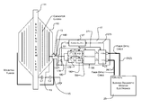
- FIG. 3 is a simplified block diagram of a high voltage bushing coupler circuit whose input is coupled to a bushing test tap and whose output is optically coupled to bushing monitoring circuitry in accordance with the invention
- FIG. 3A is a more detailed block diagram of a high voltage bushing coupler whose input is coupled to a bushing test tap and whose output is optically coupled to monitoring circuitry in accordance with the invention
- FIG. 3B is another block diagram of a high voltage bushing coupler whose input is coupled to a bushing test tap and whose output is optically coupled to monitoring circuitry in accordance with the invention
- FIG. 4 is a block diagram of a high voltage bushing coupler whose input is coupled to a bushing test tap and whose output is coupled to testing and monitoring circuitry via electromagnetic radiation (RF) circuitry in accordance with the invention
- FIG. 5 is a simplified block diagram of a high voltage bushing coupler whose input is coupled to a bushing test tap and whose output is coupled to testing and monitoring circuitry via RF circuitry in accordance with the invention.
- FIG. 6 is a semi schematic semi block diagram of a rectifying power supply for use in practicing the invention.
- FIG. 1 is a schematic diagram of a three phase delta to wye power transformer (with the neutral grounded), encased in a transformer tank, used in a typical power transmission system for a step down application.
- the voltages applied to the primary of this transformer can vary over a wide range (e.g., from less than 69 kV to more than 765 kV) while voltages on the secondary (at X 1 , X 2 , X 3 ) can also vary over a wide range (e.g., from less than 13.2 kV to more than 345 kV).
- the connections of each input and output line to the transmission or distribution system is made through an insulated bushing 10 .
- each bushing includes a test tap 13 (meeting standards as set in IEEE Std. C57.19.01-2001) with two capacitors (C 1 , C 2 ), corresponding to the capacitive layers, being connected to the test tap.
- capacitor C 1 has one side connected to the high voltage draw lead 11 and its other side connected to test tap 13 and capacitor C 2 is connected between test tap 13 and ground terminal 15 .
- the bushing test tap 13 may be selectively grounded (e.g., via a metal cover plate that bonds the bushing test tap to ground) to reduce the stressing of capacitor C 2 .
- Capacitors C 1 and C 2 may be formed in any suitable manner.
- capacitors C 1 and C 2 may be constructed of a metalized or electrically conductive ink layer to form one side of a capacitor on an insulating substrate.
- the insulating substrate for C 1 and C 2 is typically manufactured from cellulose but could be made of other high dielectric strength insulating materials.
- the insulating substrate may be immersed in an insulating liquid to improve the dielectric strength.
- known bushing monitoring schemes include circuitry for connecting to the bushing tap 13 via metallic conductors or isolation transformers (see prior art FIG. 2 ) to the measurement and monitoring circuitry.
- a drawback of the known methods is that if the capacitor layer (e.g., corresponding to C 1 ) degrades significantly (e.g., shorts) an inordinately high voltage is applied to the monitoring electronics which would be destructive to the equipment and potentially lethal to any operator of the equipment. In all cases, this poses a great hazard to those that might be nearby or in contact with the equipment when this failure occurs.
- safety or protective measures such as a surge arrester may be included to try to minimize the over voltage hazards.
- these protective and safety devices have been known to fail rendering the protection useless and the danger very real.
- the voltage at the test tap of a bushing is coupled to a bushing coupler which includes electronic circuitry necessary to sense and process the signal voltages generated at the test tap in order to assess the condition of the bushing.
- the voltage signals sensed and processed in a bushing coupler embodying the invention are converted to corresponding data signals which are wirelessly transmitted to a bushing monitoring system (e.g., a receiver also identified as a bushing diagnostic monitor electronics 25 in FIG. 3 or 251 in FIG. 4 ).
- wireless transmission embodying the invention examples include an optical coupling arrangement as shown in FIGS. 3, 3A and 3B .
- Other examples of wireless transmission include an RF transmission arrangement (as shown in FIGS. 4 and 5 ) whereby the receiver is physically isolated from the bushing coupler and the test tap. Consequently, the high voltage signal source (test tap and/or bushing coupler) has no conductive (or transformer) contact with the receiver.
- FIG. 3 shows that the voltage at tap 13 is applied to a signal conditioning circuit 18 which includes circuitry for sensing the tap voltage and for protecting against overvoltage conditions and for producing a conditioned signal at an output.
- the conditioned output signal of the signal conditioning circuit 18 is applied to an analog to digital (A/D) converter circuit 20 which functions to convert the conditioned output voltage from the conditioning circuit 18 to data signals (e.g., which vary between zero to 5 volts in amplitude) which correspond to, and are representative of, the voltage values.
- A/D converter circuit 20 which functions to convert the conditioned output voltage from the conditioning circuit 18 to data signals (e.g., which vary between zero to 5 volts in amplitude) which correspond to, and are representative of, the voltage values.
- digital signals of fixed amplitude are propagated from the output of A/D converter 20 to a microprocessor (also referred to as processor) 21 .
- the fixed amplitude of the signals is determined by the voltage output of the power supply.
- Processor 21 functions to analyze the digital signals and to format the digital signals from the A/D converter 20 and to produce corresponding data signals at a transmitting output (Tx) which are applied to an input of a fiber optic (FO) module 23 .
- FO module 23 functions to convert the formatted digital data signals into optical (light) signals which are wirelessly transmitted to fiber optics (FO) cable [ 24 ( 1 ), 24 ( 2 )].
- the FO cable [ 24 ( 1 ), 24 ( 2 )] is connected to a bushing monitoring system 25 also identified as bushing diagnostic monitor electronics device 25 .
- Device 25 includes circuitry for reconverting the received optic signals to digital signals. Thus, signals corresponding to the test tap voltage are wirelessly transmitted to and received by device 25 .
- Device 25 includes electronic circuitry for analyzing (a) the signals corresponding to the test tap voltage and (b) information corresponding to the line voltage (i.e., the high voltage applied to terminal 11 ).
- Device 25 may also include alarms outputs and DNP 3.0, MODBUS, or IEC 61850 communications protocol interface indicating the condition of the bushing and its capacitors. Device 25 may thus be used to track the state of the bushing including selected parameters and to provide appropriate alarms and displays of its condition.
- FIG. 3 also shows that bushing coupler 17 includes a power supply 27 coupled via a switch S 1 to the voltage tap 13 .
- the power supply 27 is designed to produce a direct current (DC) voltage which is distributed to the various circuits (e.g., 18 , 20 , 21 , 23 ) of the bushing coupler via lines 271 .
- DC direct current
- the power supply 27 may also be charged or recharged wirelessly by signals (Rx) produced in FO module 23 in response to optic signals generated in device 25 and transmitted to FO module 23 via cables 24 ( 1 ), 24 ( 2 ).
- the signal conditioning circuitry 18 of the bushing coupler 17 is shown to include a shunt resistor 172 , a varistor 174 , a low pass filter 178 and a high pass filter 180 .
- the outputs of the filters are applied to analog to digital (A/D) converters 182 and 184 (which correspond to A/D converter 20 of FIG. 3 ).
- the outputs of the A/D converters are applied to a microprocessor 186 (which corresponds to processor 21 of FIG. 3 ) and whose output is fed to fiber optic (FO) converter 23 .
- a temperature probe 190 shown connected to tap 13 , is used to sense the temperature of the bushing.
- the probe 190 supplies temperature signals to the processor 186 since the temperature is a significant factor in determining the value of the bushing capacitors.
- the operation of the bushing coupler 17 is generally as follows.
- the voltage present at the tap 13 is applied to filters 178 and 180 whose outputs are respectively fed to A/D converters 182 and 184 .
- the filter 178 coupled to A/D 182 may be used for measurement of partial discharge signals at the bushing tap and filter 180 and A/D converter 184 may be used to measure C 1 capacitance.
- the A/D converters function to convert the amplitude of the test tap voltages into corresponding digital signals which are then fed to signal processor 186 .
- the signal processor 186 is programmed to analyze the data signals and to format the signals to render the data signals suitable for transmission.
- the formatted transmitted output signals (Tx) of the processor 186 are then fed to an electric signal to fiber optic (FO) converter 23 , which converts the electric signals to optical signals which are wirelessly transmitted onto fiber optic cables 24 ( 1 ), 24 ( 2 ).
- FIG. 3B is intended to illustrate that the voltage, sensing and processing circuitry ( 18 , 20 , 21 ) produces data signals (Tx) which are supplied to and modulate one (or more) light emitting diode(s) (LED), located within an FO module 23 .
- the light signals from the LED are wirelessly transmitted to fiber optic cables 24 .
- the optical signals are transmitted along cable 24 to photoreceptors (e.g., photodiode) located in bushing diagnostic monitor 25 connected to diagnostic electronics (not shown). Note that there is no conductive connection between the light emitters LED and the fiber optic cable 24 and between the cable 24 and the photodiode. Accordingly, the light receptors are electrically and physically isolated from the test tap voltage.
- the characteristics and representations of the AC voltage signals at the test tap 13 are converted into corresponding digital signals within the bushing coupler so that the actual voltages present at the tap 13 are not propagated.
- the data signals corresponding to the voltages are wirelessly transmitted via a module 23 to the bushing monitoring system 25 without the use of any metallic conductive path.
- module 23 the electrical signals are dielectrically isolated from the output optic signals.
- the light output signals from module 23 are then coupled via optic fiber cables to a monitoring electronic system 25 .
- capacitor C 1 degrades completely (i.e., shorts)
- the voltages and/or currents produced at test tap 13 are not conductively (or physically) coupled to any circuitry beyond the electric to optic interface of FO converter 23 .
- the fiber optic module(s) 23 converts digitally encoded electrical input signals into one or more FO (fiber optical) output signals.
- Fiber optics is a technology that uses glass (or plastic) threads (fibers) to transmit data.
- a fiber optic cable consists of a bundle of glass threads, each of which is capable of transmitting messages modulated onto light waves.
- the fiber optic cables can be run to the bushing monitor 25 to enable the coupling of signals indicative of the voltages at tap 13 without coupling any portion of the physical voltage itself.
- the bushing coupler 17 includes a power supply 27 which is coupled via switch S 1 to tap 13 .
- the voltage at tap 13 may be fed to a rectifier circuit which, for example, as shown in FIG. 6 includes a limiting resistor, R 5 , a rectifying diode D 5 and a relatively large capacitor C 5 (shown for example to have a value of 47 Farads).
- the output of the rectifier circuit is fed to a voltage regulator 61 whose output is applied to line 271 to power the bushing circuitry with a regulated direct current (DC) voltage.
- DC direct current
- the power generated by power supply 27 is shown to be distributed via line(s) 271 . It should be noted that the electrical power obtainable from the test tap 13 may be insufficient to operate the bushing circuitry. Therefore, an aspect of the invention includes circuitry for wirelessly providing power from an external source to the power supply 27 in addition to, or as an alternative to, the power derived from the bushing test tap.
- the power supply 27 may be charged or recharged by monitor 25 supplying optical signals to module 23 which includes circuitry for converting the optical signals to electric signals which can then be processed to produce DC voltages coupled via line 273 and isolation diode D 6 to power supply 27 for charging or recharging the power supply 27 .
- the optic to electric signal conversion is done to ensure that the power supply system for the bushing coupler 17 and the signal processing are dielectrically isolated from all equipment and that potential hazards are avoided without the need for batteries or an electrical connection to supply power from an external source.
- selected power signals may be supplied to light emitters LE 2 in bushing monitoring system 25 which are optically (wirelessly) transmitted via optic cable 24 to light receptors LR 2 (e.g., a solar cell or any suitable photovoltaic device).
- the light signals are wirelessly (optically) transmitted to the light receptors, such as solar or photovoltaic cells, which signals are then converted to a direct current (DC) voltage which can be supplied via line 273 to power supply 27 .
- DC direct current
- FIGS. 3, 3A and 3B also show that either a measured value of line voltage or the highly accurate line voltage information obtained from the utility EMS is applied to the monitoring system 25 .
- the monitoring system 25 includes circuitry for comparing the tap voltage obtained from the bushing coupler with the accurate line voltage to calculate the value of C 1 which can then be used to determine the status and/or condition of the bushing being monitored.
- a method to determine variation in the value of C 1 is achieved by reporting tap voltage developed off a low inductance precision resistor (R 172 in FIG. 3A ) to the bushing analysis and monitoring device 25 .
- the tap voltage is transmitted wirelessly via the fiber optic connection from the bushing coupler to the bushing analysis device 25 .
- the bushing monitoring device 25 is also designed to receive values of the high voltage (HV) applied to the bushing terminal 11 .
- the value of the high voltage can be obtained, for example, by means of measurements or from a potential transformer in the substation or received from the utility's energy management system via either DNP 3.0, MODBUS, or IEC 61850. It is preferable to use the most accurate value available. Values of C 1 can be calculated by using the following equation:
- C 1 1 2 ⁇ ⁇ ⁇ ⁇ fR ⁇ ( V LINE V TAP ) 2 - 1
- C1 Upper Bushing Capacitor Layer(s)
- f Line frequency (50 or 60 Hz)
- R Shunt Resistor From the Bushing Tap to Ground
- V TAP Voltage at the Bushing Tap
- V LINE Measured or Reported Bus Voltage
- the calculations for determining C 1 is made by appropriately programming the monitoring circuitry 25 which can also display the information in various forms. This can be done and displayed automatically and/or with the aid of an operator. Because of the wireless transmission of the signals the measurements can be conducted without concern of injury or damage due to the high line voltages.
- Each bushing coupler 17 is preferably encased in a metal container which is grounded.
- the measuring circuitry is typically located in a transformer control cabinet or its own cabinet perhaps with other monitoring equipment.
- the bushing coupler of FIG. 4 is similar to that of FIG. 3A except that the output signals (Tx) of the processor 186 are fed to a radio frequency (RF) transceiver 231 which is coupled to an antenna 212 which can transmit via RF transmission to antenna 214 which is coupled to a bushing monitor electronics 251 , which functions in a similar manner to monitor 25 .
- the RF transceiver 231 includes a radio frequency (RF) module device used to “wirelessly” transmit and/or receive radio signals between the processor 186 and the monitor 251 .
- RF radio frequency
- the wireless communication is accomplished through optical communication.
- FIGS. 4 and 5 the wireless communication is through Radio Frequency (RF) communication.
- RF Radio Frequency
- the bushing couplers of FIGS. 4 and 5 like the ones of FIGS. 3, 3A and 3B enable the characteristics and representations of the signal at the test tap 13 to be transmitted “wirelessly” to their respective monitor 251 .
- the wireless transmission of data to the receiver 251 ensures that the potentially dangerous high voltages at the test tap are not conductively or physically coupled to the receiver
- FIG. 5 is like FIG. 3B except that it illustrates that the transceiver 231 may include modulator and demodulator circuitry for modulating and demodulating the signals being transmitted.
- the output signals (Tx) may be fed via the modulator and RF circuitry to antenna 21 for transmission to antennae 214 and decoding within the monitor 251 to effectuate wireless, nonconductive, transmission of the signals form the bushing coupler to the bushing monitoring system.
- FIGS. 4 and 5 show that, in an analogous manner to the showing in FIGS. 3, 3A and 3B , the power for the bushing coupler 17 can be obtained from RF signals emanating from the monitor electronics 251 . That is, selected RF power signals from the monitor 251 can be wirelessly transmitted via antenna 214 to antenna 212 which is coupled to transceiver 231 where they are demodulated. The demodulated RF signals then produce a DC voltage which can be coupled via line 273 to power supply 27 to charge or recharge the power supply 27 in an analogous manner to that described above.
- the monitor 251 (like monitor 25 ) is programmed to calculate C 1 .
- Line voltage information is supplied to monitor 251 , where the line voltage can either be a measured value or it can be a highly accurate value supplied by a utility. The information can be continuously monitored and displayed safely without concern of being injured or damaged by a high voltage.
- a bushing coupler embodying the invention includes electronic circuitry for sensing the AC waveform at the bushing tap and circuitry for converting the sensed voltage to corresponding data signals. It also includes circuitry for wirelessly transmitting the data signals to a receiver physically and dielectrically isolated from the bushing coupler.
- the bushing coupler has its own power supply which is designed to accept either AC or DC input voltages and which provides an extremely high level of isolation in the event of a complete failure of the capacitance layer in the bushing.
- the bushing coupler's power supply can be charged by wirelessly transmitting energy from an outside source to the power supply
Landscapes
- Physics & Mathematics (AREA)
- General Physics & Mathematics (AREA)
- Measuring Instrument Details And Bridges, And Automatic Balancing Devices (AREA)
Abstract
Description
Where:
C1=Upper Bushing Capacitor Layer(s);
f=Line frequency (50 or 60 Hz);
R=Shunt Resistor From the Bushing Tap to Ground;
VTAP=Voltage at the Bushing Tap; and
VLINE=Measured or Reported Bus Voltage
Claims (20)
Priority Applications (1)
| Application Number | Priority Date | Filing Date | Title |
|---|---|---|---|
| US14/303,591 US9482699B2 (en) | 2013-06-18 | 2014-06-12 | Method and apparatus for monitoring high voltage bushings safely |
Applications Claiming Priority (2)
| Application Number | Priority Date | Filing Date | Title |
|---|---|---|---|
| US201361956835P | 2013-06-18 | 2013-06-18 | |
| US14/303,591 US9482699B2 (en) | 2013-06-18 | 2014-06-12 | Method and apparatus for monitoring high voltage bushings safely |
Publications (2)
| Publication Number | Publication Date |
|---|---|
| US20140368215A1 US20140368215A1 (en) | 2014-12-18 |
| US9482699B2 true US9482699B2 (en) | 2016-11-01 |
Family
ID=52018689
Family Applications (1)
| Application Number | Title | Priority Date | Filing Date |
|---|---|---|---|
| US14/303,591 Active 2035-05-12 US9482699B2 (en) | 2013-06-18 | 2014-06-12 | Method and apparatus for monitoring high voltage bushings safely |
Country Status (3)
| Country | Link |
|---|---|
| US (1) | US9482699B2 (en) |
| EP (1) | EP3030913A4 (en) |
| WO (1) | WO2014204819A1 (en) |
Cited By (4)
| Publication number | Priority date | Publication date | Assignee | Title |
|---|---|---|---|---|
| US10649009B2 (en) | 2018-03-27 | 2020-05-12 | G & W Electric Company | Ungrounded control of low energy analog (LEA) voltage measurements |
| US11067610B2 (en) | 2018-12-28 | 2021-07-20 | Palo Alto Research Center Incorporated | Partial discharge detector |
| US11287463B2 (en) | 2018-12-28 | 2022-03-29 | Palo Alto Research Center Incorporated | Partial discharge transducer |
| US11486919B2 (en) | 2019-10-24 | 2022-11-01 | Palo Alto Research Center Incorporated | Partial discharge sensor |
Families Citing this family (16)
| Publication number | Priority date | Publication date | Assignee | Title |
|---|---|---|---|---|
| EP3186646B1 (en) * | 2014-08-29 | 2021-10-20 | Aclara Technologies LLC | Power extraction for a medium voltage sensor using a capacitive voltage divider |
| HUE035641T2 (en) * | 2015-03-17 | 2018-05-28 | Abb Schweiz Ag | A method for monitoring transformer bushings, and a system therefor |
| US10126348B2 (en) * | 2015-04-29 | 2018-11-13 | ZTZ Service International, Inc. | Combined on-line bushing monitoring and geo-magnetic induced current monitoring system |
| WO2018108828A1 (en) * | 2016-12-16 | 2018-06-21 | Eaton Industries (Netherlands) B.V. | Combination of an electricity conducting element, such as bushing, and a connector cable |
| CN107561419B (en) * | 2017-08-24 | 2019-02-22 | 西南交通大学 | A kind of appraisal procedure of oil-immersed sleeve pipe insulation bubble effect risk |
| CN107621574B (en) * | 2017-08-25 | 2019-01-25 | 西南交通大学 | Study the experimental method of loading condition setting of casing interior insulation moisture distribution |
| CN107576856B (en) * | 2017-08-25 | 2018-12-25 | 西南交通大学 | A kind of bushing interior insulation is unevenly made moist the method for experiment |
| CN112840516B (en) | 2018-09-10 | 2023-03-31 | 3M创新有限公司 | Support structure for cable and cable accessory condition monitoring device |
| WO2020055666A1 (en) * | 2018-09-10 | 2020-03-19 | 3M Innovative Properties Company | Electrical power cable monitoring device using low side electrode and earth ground separation |
| EP3850381A2 (en) * | 2018-09-10 | 2021-07-21 | 3M Innovative Properties Company | Electrical power cable monitoring device including partial discharge sensor |
| US10732164B2 (en) | 2018-12-12 | 2020-08-04 | ZTZ Service International, Inc. | System and method for headspace monitoring in transformers |
| EP3715881B1 (en) * | 2019-03-28 | 2023-05-17 | Siemens Energy Global GmbH & Co. KG | Method for maintenance of a high-voltage bushing |
| CN111092449A (en) * | 2019-11-21 | 2020-05-01 | 上海交通大学 | High-voltage system hundred megawatt battery energy storage system |
| WO2021138569A1 (en) | 2019-12-31 | 2021-07-08 | 3M Innovative Properties Company | Monitoring system for evaluating a condition of an electrical grid |
| GB2590987A (en) * | 2019-12-31 | 2021-07-14 | Eaton Intelligent Power Ltd | Sensor part for installation in medium-voltage cable compartments and a device for measuring a voltage in medium-voltage circuits comprising such sensor part |
| CN111307218A (en) * | 2020-03-16 | 2020-06-19 | 国网河南省电力公司电力科学研究院 | Transformer bushing monitoring system |
Citations (7)
| Publication number | Priority date | Publication date | Assignee | Title |
|---|---|---|---|---|
| US4757263A (en) * | 1987-05-01 | 1988-07-12 | Tennessee Valley Authority | Insulation power factor alarm monitor |
| US4914382A (en) * | 1987-10-14 | 1990-04-03 | Hydro-Quebec | High voltage measuring circuit coupled to the capacitive grounding tap bushing of an HV device |
| US5903158A (en) * | 1995-05-02 | 1999-05-11 | Abb Research, Ltd. | Monitoring of internal partial discharges in a power transformer |
| US6538422B2 (en) * | 2000-04-26 | 2003-03-25 | S & C Electric Co. | Voltage sensor bushing assembly with integral capacitance screen |
| US6927562B2 (en) * | 2002-02-27 | 2005-08-09 | On-Line Monitoring, Inc. | Power factor/tan δtesting of high voltage bushings on power transformers, current transformers, and circuit breakers |
| US7126348B2 (en) * | 2002-12-20 | 2006-10-24 | Abb Ab | Method and a device for voltage measurement in a high-voltage conductor |
| US20150355237A1 (en) * | 2013-01-23 | 2015-12-10 | Siemens Aktiengesellschaft | Measuring System for Continuously Monitoring a High-Voltage Bushing |
Family Cites Families (15)
| Publication number | Priority date | Publication date | Assignee | Title |
|---|---|---|---|---|
| CA939747A (en) * | 1970-04-08 | 1974-01-08 | Doble Engineering Company | In-service bushing test |
| US4295094A (en) * | 1979-04-30 | 1981-10-13 | Westinghouse Electric Corp. | High voltage high frequency analog signal measuring system |
| JPH0738011B2 (en) * | 1988-05-16 | 1995-04-26 | 株式会社日立製作所 | Abnormality diagnosis system for high-voltage power equipment |
| US5181026A (en) * | 1990-01-12 | 1993-01-19 | Granville Group, Inc., The | Power transmission line monitoring system |
| US5574378A (en) * | 1994-12-15 | 1996-11-12 | Square D Company | Insulation monitoring system for insulated high voltage apparatus |
| US6177803B1 (en) * | 1995-06-07 | 2001-01-23 | Doble Engineering Company | Monitoring elements in a multi-phase alternating current network |
| US6433557B1 (en) * | 2000-12-21 | 2002-08-13 | Eaton Corporation | Electrical system with capacitance tap and sensor for on-line monitoring the state of high-voltage insulation and remote monitoring device |
| CN100505120C (en) | 2004-11-01 | 2009-06-24 | 王如璋 | Dry type mutual inductor with optical signal output |
| US7295133B1 (en) * | 2004-12-30 | 2007-11-13 | Hendrix Wire & Cable, Inc. | Electrical circuit monitoring device |
| GB0517994D0 (en) * | 2005-09-05 | 2005-10-12 | Univ Glasgow | High voltage insulation monitoring sensor |
| JP4908146B2 (en) * | 2006-10-12 | 2012-04-04 | 株式会社東芝 | High voltage equipment with IC tag with sensor |
| US20090015239A1 (en) * | 2007-03-01 | 2009-01-15 | Georgiou George E | Transmission Line Sensor |
| ATE526588T1 (en) | 2009-08-07 | 2011-10-15 | Omicron Electronics Gmbh | SYSTEM FOR MONITORING A TRANSFORMER |
| US9110117B2 (en) | 2010-04-16 | 2015-08-18 | Avo Multi-Amp Corporation | System and method for detecting voltage dependence in insulation systems based on harmonic analysis |
| CN102540034B (en) | 2012-03-16 | 2014-05-28 | 甘肃电力科学研究院 | High-voltage transformer bushing tap grounding on-line monitoring device |
-
2014
- 2014-06-12 US US14/303,591 patent/US9482699B2/en active Active
- 2014-06-15 WO PCT/US2014/042446 patent/WO2014204819A1/en active Application Filing
- 2014-06-15 EP EP14813687.2A patent/EP3030913A4/en active Pending
Patent Citations (7)
| Publication number | Priority date | Publication date | Assignee | Title |
|---|---|---|---|---|
| US4757263A (en) * | 1987-05-01 | 1988-07-12 | Tennessee Valley Authority | Insulation power factor alarm monitor |
| US4914382A (en) * | 1987-10-14 | 1990-04-03 | Hydro-Quebec | High voltage measuring circuit coupled to the capacitive grounding tap bushing of an HV device |
| US5903158A (en) * | 1995-05-02 | 1999-05-11 | Abb Research, Ltd. | Monitoring of internal partial discharges in a power transformer |
| US6538422B2 (en) * | 2000-04-26 | 2003-03-25 | S & C Electric Co. | Voltage sensor bushing assembly with integral capacitance screen |
| US6927562B2 (en) * | 2002-02-27 | 2005-08-09 | On-Line Monitoring, Inc. | Power factor/tan δtesting of high voltage bushings on power transformers, current transformers, and circuit breakers |
| US7126348B2 (en) * | 2002-12-20 | 2006-10-24 | Abb Ab | Method and a device for voltage measurement in a high-voltage conductor |
| US20150355237A1 (en) * | 2013-01-23 | 2015-12-10 | Siemens Aktiengesellschaft | Measuring System for Continuously Monitoring a High-Voltage Bushing |
Cited By (6)
| Publication number | Priority date | Publication date | Assignee | Title |
|---|---|---|---|---|
| US10649009B2 (en) | 2018-03-27 | 2020-05-12 | G & W Electric Company | Ungrounded control of low energy analog (LEA) voltage measurements |
| US10948521B2 (en) | 2018-03-27 | 2021-03-16 | G & W Electric Company | Ungrounded control of low energy analog (LEA) voltage measurements |
| US11067610B2 (en) | 2018-12-28 | 2021-07-20 | Palo Alto Research Center Incorporated | Partial discharge detector |
| US11287463B2 (en) | 2018-12-28 | 2022-03-29 | Palo Alto Research Center Incorporated | Partial discharge transducer |
| US11802901B2 (en) | 2018-12-28 | 2023-10-31 | Xerox Corporation | Partial discharge transducer |
| US11486919B2 (en) | 2019-10-24 | 2022-11-01 | Palo Alto Research Center Incorporated | Partial discharge sensor |
Also Published As
| Publication number | Publication date |
|---|---|
| EP3030913A4 (en) | 2017-05-24 |
| US20140368215A1 (en) | 2014-12-18 |
| EP3030913A1 (en) | 2016-06-15 |
| WO2014204819A1 (en) | 2014-12-24 |
Similar Documents
| Publication | Publication Date | Title |
|---|---|---|
| US9482699B2 (en) | Method and apparatus for monitoring high voltage bushings safely | |
| US10627431B2 (en) | Combined in-line DC and AC current sensor for high voltage electric power lines | |
| CN101682188B (en) | Power station for power transmission to remotely located load | |
| US5574378A (en) | Insulation monitoring system for insulated high voltage apparatus | |
| US20080087115A1 (en) | Sensor attached ic tag application high voltage equipment | |
| WO2019194754A1 (en) | Link box with built-in insulator type voltage divider and inductive partial discharge sensor | |
| KR102104835B1 (en) | Gis for 29kv with prevention apparatus for secondary circuit opening of current transformer | |
| WO1999042844A1 (en) | Power monitoring apparatus | |
| CN103675597A (en) | Method of testing a fuse | |
| WO2016190823A1 (en) | Link box with built-in partial discharge sensor | |
| RU119120U1 (en) | DEVICE FOR VOLTAGE MEASUREMENT IN A HIGH VOLTAGE CIRCUIT WITH REMOTE INFORMATION TRANSMISSION | |
| CN105807193B (en) | A kind of same frequency with safe sampled signal is the same as phase Withstand test device | |
| CN106483487A (en) | A kind of on-line monitoring Intelligent current transformer | |
| RU121594U1 (en) | DEVICE FOR VOLTAGE MEASUREMENT IN A HIGH VOLTAGE CIRCUIT WITH REMOTE INFORMATION TRANSMISSION | |
| CN207366648U (en) | A kind of control measuring circuit of power frequency continued flow experimental rig | |
| JP4257839B2 (en) | Ground fault detection device for power cable shielding conductor | |
| CN104981708B (en) | For the processor device handled the signal in electric power facility | |
| EP4177615A1 (en) | Monitoring device, electrical installation and monitoring method | |
| EP3106888B1 (en) | Method and system for partial discharge measurement on a power cable | |
| US9977055B2 (en) | Isolation interface for an electricity meter and electricity metering system | |
| RU2482503C1 (en) | Device to measure voltage in high-voltage circuit with remote data transfer | |
| CN217484487U (en) | Transformer state monitoring system | |
| CN219512379U (en) | Alternating current-channeling direct current alarm device of transformer substation | |
| CN210270121U (en) | Short circuit test system between winding strands | |
| JP7456868B2 (en) | Connection body deterioration diagnosis device and connection body deterioration diagnosis method |
Legal Events
| Date | Code | Title | Description |
|---|---|---|---|
| AS | Assignment |
Owner name: ADVANCED POWER TECHNOLOGIES, LLC, NEW JERSEY Free format text: ASSIGNMENT OF ASSIGNORS INTEREST;ASSIGNORS:HOFFMAN, GARY R.;KWON, EDWARD S.;BENIS, MIKHAIL;REEL/FRAME:033202/0790 Effective date: 20140613 |
|
| STCF | Information on status: patent grant |
Free format text: PATENTED CASE |
|
| FEPP | Fee payment procedure |
Free format text: MAINTENANCE FEE REMINDER MAILED (ORIGINAL EVENT CODE: REM.); ENTITY STATUS OF PATENT OWNER: SMALL ENTITY |
|
| FEPP | Fee payment procedure |
Free format text: SURCHARGE FOR LATE PAYMENT, SMALL ENTITY (ORIGINAL EVENT CODE: M2554); ENTITY STATUS OF PATENT OWNER: SMALL ENTITY |
|
| MAFP | Maintenance fee payment |
Free format text: PAYMENT OF MAINTENANCE FEE, 4TH YR, SMALL ENTITY (ORIGINAL EVENT CODE: M2551); ENTITY STATUS OF PATENT OWNER: SMALL ENTITY Year of fee payment: 4 |