US9479762B2 - Stereoscopic video temporal frame offset measurement - Google Patents
Stereoscopic video temporal frame offset measurement Download PDFInfo
- Publication number
- US9479762B2 US9479762B2 US13/310,972 US201113310972A US9479762B2 US 9479762 B2 US9479762 B2 US 9479762B2 US 201113310972 A US201113310972 A US 201113310972A US 9479762 B2 US9479762 B2 US 9479762B2
- Authority
- US
- United States
- Prior art keywords
- cross
- signature
- frame offset
- image sequences
- right image
- Prior art date
- Legal status (The legal status is an assumption and is not a legal conclusion. Google has not performed a legal analysis and makes no representation as to the accuracy of the status listed.)
- Expired - Fee Related, expires
Links
Images


Classifications
-
- H04N13/0296—
-
- H—ELECTRICITY
- H04—ELECTRIC COMMUNICATION TECHNIQUE
- H04N—PICTORIAL COMMUNICATION, e.g. TELEVISION
- H04N13/00—Stereoscopic video systems; Multi-view video systems; Details thereof
- H04N13/20—Image signal generators
- H04N13/296—Synchronisation thereof; Control thereof
-
- H04N13/0051—
-
- H—ELECTRICITY
- H04—ELECTRIC COMMUNICATION TECHNIQUE
- H04N—PICTORIAL COMMUNICATION, e.g. TELEVISION
- H04N13/00—Stereoscopic video systems; Multi-view video systems; Details thereof
- H04N13/10—Processing, recording or transmission of stereoscopic or multi-view image signals
- H04N13/106—Processing image signals
- H04N13/167—Synchronising or controlling image signals
-
- H—ELECTRICITY
- H04—ELECTRIC COMMUNICATION TECHNIQUE
- H04N—PICTORIAL COMMUNICATION, e.g. TELEVISION
- H04N13/00—Stereoscopic video systems; Multi-view video systems; Details thereof
- H04N2013/0074—Stereoscopic image analysis
- H04N2013/0096—Synchronisation or controlling aspects
Definitions
- the present invention relates to three-dimensional (3D) television (TV) video processing, and more particularly to the measurement of stereoscopic video temporal frame offset.
- Stereoscopic three-dimensional television (3DTV) video is a sequence of stereoscopic frame-pairs.
- One of the frames in each frame-pair is intended for viewing by the Left Eye only, and the other frame is intended for viewing by the Right Eye only.
- the binocular vision of the frame-pair creates the stereoscopic illusion of depth along with the traditional image height and width.
- These frame-pairs may be separate video streams of the Left Eye (L) image frames and the Right Eye (R) image frames.
- Each stream is generally taken from a 3D camera system that is really two cameras with separate video outputs to produce a serial digital dual link. It is desirable that the two cameras are synchronized so that the L and R frame-pairs are captured at the same time.
- These dual-link outputs may be sent as separate compressed video streams to a location where the image pairs are combined with one of several methods to produce a single stream for distribution.
- Each stream may be compressed with a separate coder/decoder (CODEC), one for the L image sequence and one for the R image sequence.
- CODEC coder/decoder
- each CODEC often has an undetermined frame delay or processing latency.
- the decompressed output sequence of L and R frames may no longer be pair-wise, frame synchronous, i.e., there may be one or more frames of temporal miss-alignment or temporal frame offset.
- the present invention provides a stereoscopic video temporal frame offset measurement technique that is robust, and does not require any a priori knowledge of video content.
- the stereoscopic video temporal frame offset measurement system uses an improved signature curve generator to generate a robust signature curve for each of the left and right image sequences of a stereo video signal.
- the resulting signature curves are cross-correlated over a specified correlation range to generate cross-correlation coefficients.
- the cross-correlation coefficients are compared to a high threshold, and a temporal frame offset is generated and displayed for each cross-correlation coefficient that exceeds the high threshold.
- Each new, reliable temporal frame offset result is highlighted when displayed, otherwise the last result is displayed in a background fashion.
- FIG. 1 provides a block diagram view of an improved signature curve generator for the measurement of stereoscopic video temporal frame offset according to the present invention.
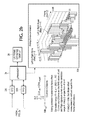
- FIG. 2 provides a block diagram view of the system for stereoscopic view temporal frame offset measurement according to the present invention.
- FIG. 3 provides a block diagram view of the signature curve generator having reduced hardware requirements according to the present invention.
- FIG. 4 provides a block diagram view of an input filter for further reducing the hardware requirement according to the present invention.
- a sequence of luminance images, Y f (n), is input to a temporal signature curve (C f ) generator 10 to produce a frame-to-frame cross-variance output as described in the above-mentioned U.S. Pat. No. 6,752,360.
- the luminance sequence is input to a high-pass filter (HPF) 12 to produce a sequence of high-pass filtered luminance images, Yh f (n), which in turn is input to a frame/field delay circuit 14 that provides an output sequence of luminance images, Yh f-1 (n), that are delayed by one frame/field.
- HPF high-pass filter
- the two resulting sequences of luminance images are input to a multiply-accumulate circuit 16 effecting an un-normalized cross-correlation, also known as a co-variance measure, to produce the SC, C f , according to the prior art, and which is graphed as FIG. 1 a .
- SC is further processed by a differentiator 18 that provides a normalized first-past difference, Cd f , of the frame-to-frame cross-correlation, C f , a graph of which is shown in FIG. 1 b .
- Cd f is normalized by the number of frames, N, as shown in FIG. 1 b . It is apparent by comparing the two graphs of FIGS. 1 a and 1 b that now variations are readily apparent, i.e., the dynamic range of the SC is significantly reduced and the AC content is increased.
- luminance component pixels, YL f (n) and YR f (n), of a stereoscopic image pair are applied to a dual SC generator 20 to produce the first-past differences, CLd f and CRd f .
- Each pixel, indexed by n, of the input and output frame/field of the frame/field delay 14 is then cross-correlated, without normalization to the individual standard deviations, by the multiply-accumulate circuit 16 to produce the covariance measure of the frame difference of each input frame, indexed by f, and the previous frame, indexed by f ⁇ 1.
- the improved temporal signal curves of the L and R image sequences are shown superimposed in the graph shown in FIG. 2 .
- the right channel skipped a frame so the signature curves are not synchronous, i.e., after the frame skip there is a one frame offset between the two channels.
- the respective first-past differences are input to respective first-in/first-out (FIFO) buffers 22 L, 22 R having a length equal to twice a specified correlation range R.
- the outputs from the FIFO buffers 22 are available to a typical microprocessor and memory system 24 .
- the microprocessor and memory system 24 computes a sliding correlation, as illustrated in FIG. 2 .
- the microprocessor 24 reads past samples of CLd and CRd from the FIFO buffers 22 within the real-time frame processing hardware after a sufficient record of frame-rate samples have been acquired.
- the record length as indicated above, is 2 ⁇ R, where R is the correlation computation range and offset detection range, as shown in the equation of FIG. 2 .
- the root mean square (rms) values over the correlation range R of the respective CLd and CRd are used in the denominator of the shown equation to create a normalized correlation coefficient ranging from ⁇ 1 to +1. Therefore there is the possibility that, within the given computation range R, all the frames are still frames, i.e., are identical, so that the rms value of that section of the signature curve approaches zero. To avoid this situation, the microprocessor 24 tests the rms values against a minimum value, and disregards the set of frames over the correlation range R where the rms values are less than the minimum value.
- the equation shown in FIG. 2 computes a correlation coefficient, Xdc(s,f), over the range R for several frame offsets, s, to determine the best estimate of the offset between the two signature curves, CLd(f) and CRd(f).
- the range of offsets, s is from ⁇ 3 to +4 frames
- the correlation range, R is 8.
- a longer correlation range may be used to get more accuracy in the computation of Xdc(s,f).
- common methods of interpolation or sample up-conversion of CLd(f) and CRd(f) may be used prior to correlation to achieve higher time resolution to fractions of a frame/field time.
- the value of Xdc for each offset, s is tested to see if it is above a certain threshold, typically above 0.98. If the value of Xdc is above the threshold, then a reliable indication of the L to R frame offset has been found and the value of the corresponding offset, s, is displayed on an instrument display screen 26 . In the given example the value of LR Frame Offset is +1, which value is displayed. For each calculated LR Frame Offset, the resulting offset, s, is highlighted, if found to be reliable, to indicate that an update has occurred. If the readout is not updated, then the readout displayed is shown in gray or otherwise not highlighted to indicate that the last good value is shown without a recent update.
- SW software
- the YL(n) and YR(n) pixels from the L and R image sequences may be decimated by two and interleaved into a single sample stream, as illustrated in FIG. 3 .
- the pixels from the respective image sequences are input to respective low pass filters (LPF) 32 L, 32 R of a low pass filter and interleave circuit 30 , which is part of an input filter circuit 28 .
- LPF low pass filters
- the outputs from the respective LPFs 32 are input to respective decimators 34 L, 34 R, with one of the outputs from the decimators being delayed one pixel interval by a delay circuit 36 .
- the outputs from the un-delayed decimator 34 R and the delay circuit 36 are input to a multiplexer 38 to produce a single pixel stream having interleaved L and R image sequence pixels.
- the resulting single pixel stream is then input to a high pass filter (HPF) 12 ′ to remove the DC or luminance-mean component before input to the frame/field delay 14 .
- HPF high pass filter
- the input and output from the frame/field delay 14 are input to a modified multiply-accumulate circuit 16 ′ to effect a cross-correlation, producing respective CL f and CR f streams that are input to the respective differentiators 18 to produce the same SC outputs as shown in FIG. 2 .
- the single multiply-accumulate circuit 16 ′ is now effectively a cross-covariance detector, since the result is not normalized by the frame rms values.
- the separate HPF filtered L and R luminance pixels are independently accumulated for the cross-covariance between temporally adjacent frames or fields, then differentiated and normalized into the desired SC values for input to the microprocessor 24 shown in FIG. 2 .
- FIG. 4 Further simplification of the HW may be done by combining the LPF, interleaving and HPF filtering 30 , 12 ′ as shown in FIG. 4 .
- the impulse responses of the LPFs 32 and HPF 12 ′ may be combined, or convolved, into a single impulse response.
- the result then may be decomposed into a two-phase implementation and selection multiplexer, creating the desired total horizontal frequency response for each luminance component YL(n) and YR(n).
- the output is the interleaved and decimated luminance values with the combined LPF and HPF horizontal frequency response which is then input to the single frame/field delay 14 .
- FIG. 4 The upper portion of FIG.
- FIG. 4 shows a detailed block diagram of the combined polyphase interleaver finite impulse response (FIR) filter 40 , while the bottom view shows how the convolved LPF and HPF impulse responses are decomposed into separate, simplified, processing paths in the combined polyphase interleaver FIR filter.
- FIR finite impulse response
- the present invention provides a stereoscopic video time frame offset measurement system using an improved signature curve generator to produce signature curves for left and right image sequences, which signature curves are then correlated with each other to determine time frame offsets between the two image sequences.
Abstract
Description
Claims (17)
Priority Applications (4)
| Application Number | Priority Date | Filing Date | Title |
|---|---|---|---|
| US13/310,972 US9479762B2 (en) | 2011-12-05 | 2011-12-05 | Stereoscopic video temporal frame offset measurement |
| CN201210596322.8A CN103139596B (en) | 2011-12-05 | 2012-12-05 | A kind of system and method for measuring the vertical shift of three-dimensional video-frequency time |
| JP2012266181A JP6178565B2 (en) | 2011-12-05 | 2012-12-05 | Stereo video temporal frame offset measurement system and method |
| EP12195699.9A EP2603007B1 (en) | 2011-12-05 | 2012-12-05 | Stereoscopic video temporal frame offset measurement |
Applications Claiming Priority (1)
| Application Number | Priority Date | Filing Date | Title |
|---|---|---|---|
| US13/310,972 US9479762B2 (en) | 2011-12-05 | 2011-12-05 | Stereoscopic video temporal frame offset measurement |
Publications (2)
| Publication Number | Publication Date |
|---|---|
| US20130141528A1 US20130141528A1 (en) | 2013-06-06 |
| US9479762B2 true US9479762B2 (en) | 2016-10-25 |
Family
ID=47458656
Family Applications (1)
| Application Number | Title | Priority Date | Filing Date |
|---|---|---|---|
| US13/310,972 Expired - Fee Related US9479762B2 (en) | 2011-12-05 | 2011-12-05 | Stereoscopic video temporal frame offset measurement |
Country Status (4)
| Country | Link |
|---|---|
| US (1) | US9479762B2 (en) |
| EP (1) | EP2603007B1 (en) |
| JP (1) | JP6178565B2 (en) |
| CN (1) | CN103139596B (en) |
Families Citing this family (2)
| Publication number | Priority date | Publication date | Assignee | Title |
|---|---|---|---|---|
| US20150271471A1 (en) * | 2014-03-19 | 2015-09-24 | Htc Corporation | Blocking detection method for camera and electronic apparatus with cameras |
| CN104284183A (en) * | 2014-09-30 | 2015-01-14 | 重庆三峡学院 | Safety detection method and device for 3D frames |
Citations (13)
| Publication number | Priority date | Publication date | Assignee | Title |
|---|---|---|---|---|
| US6751360B1 (en) * | 2000-11-14 | 2004-06-15 | Tektronix, Inc. | Fast video temporal alignment estimation |
| US20040205570A1 (en) * | 2001-08-02 | 2004-10-14 | Fujitsu Limited | Test assisting program and test assisting method |
| EP1727376A2 (en) | 2005-05-23 | 2006-11-29 | Tektronix, Inc. | Instrument for real-time video quality measurement |
| US20080260023A1 (en) * | 2007-04-18 | 2008-10-23 | Chih-Ta Star Sung | Digital video encoding and decoding with refernecing frame buffer compression |
| US20080312906A1 (en) * | 2007-06-18 | 2008-12-18 | International Business Machines Corporation | Reclassification of Training Data to Improve Classifier Accuracy |
| US20100064001A1 (en) * | 2007-10-10 | 2010-03-11 | Power Takeoff, L.P. | Distributed Processing |
| US20100110163A1 (en) * | 2007-09-24 | 2010-05-06 | Koninklijke Philips Electronics N.V. | Method and system for encoding a video data signal, encoded video data signal, method and sytem for decoding a video data signal |
| US20100166300A1 (en) * | 2008-12-31 | 2010-07-01 | Stmicroelectronics S.R.I. | Method of generating motion vectors of images of a video sequence |
| US20110037829A1 (en) * | 2009-08-11 | 2011-02-17 | Sony Corporation | Display device, display method and computer program |
| EP2315455A2 (en) | 2009-10-25 | 2011-04-27 | Tektronix, Inc. | AV delay measurement and correction via signature curves |
| US20110242286A1 (en) * | 2010-03-31 | 2011-10-06 | Vincent Pace | Stereoscopic Camera With Automatic Obstruction Removal |
| US20110261257A1 (en) * | 2008-08-21 | 2011-10-27 | Dolby Laboratories Licensing Corporation | Feature Optimization and Reliability for Audio and Video Signature Generation and Detection |
| US20120033817A1 (en) * | 2010-08-09 | 2012-02-09 | Motorola, Inc. | Method and apparatus for estimating a parameter for low bit rate stereo transmission |
Family Cites Families (4)
| Publication number | Priority date | Publication date | Assignee | Title |
|---|---|---|---|---|
| JP2738531B2 (en) * | 1986-06-04 | 1998-04-08 | 日本放送協会 | Apparatus for detecting phase difference between image component signals |
| US6752360B2 (en) | 2002-08-14 | 2004-06-22 | Deere & Company | Hydraulic hose holder for an agricultural implement |
| US7174279B2 (en) * | 2004-03-31 | 2007-02-06 | Teradyne, Inc. | Test system with differential signal measurement |
| JP2011205388A (en) * | 2010-03-25 | 2011-10-13 | Sony Corp | Signal processing apparatus and method, and program |
-
2011
- 2011-12-05 US US13/310,972 patent/US9479762B2/en not_active Expired - Fee Related
-
2012
- 2012-12-05 JP JP2012266181A patent/JP6178565B2/en not_active Expired - Fee Related
- 2012-12-05 CN CN201210596322.8A patent/CN103139596B/en not_active Expired - Fee Related
- 2012-12-05 EP EP12195699.9A patent/EP2603007B1/en not_active Not-in-force
Patent Citations (14)
| Publication number | Priority date | Publication date | Assignee | Title |
|---|---|---|---|---|
| US6751360B1 (en) * | 2000-11-14 | 2004-06-15 | Tektronix, Inc. | Fast video temporal alignment estimation |
| US20040205570A1 (en) * | 2001-08-02 | 2004-10-14 | Fujitsu Limited | Test assisting program and test assisting method |
| EP1727376A2 (en) | 2005-05-23 | 2006-11-29 | Tektronix, Inc. | Instrument for real-time video quality measurement |
| US20080260023A1 (en) * | 2007-04-18 | 2008-10-23 | Chih-Ta Star Sung | Digital video encoding and decoding with refernecing frame buffer compression |
| US20080312906A1 (en) * | 2007-06-18 | 2008-12-18 | International Business Machines Corporation | Reclassification of Training Data to Improve Classifier Accuracy |
| US20100110163A1 (en) * | 2007-09-24 | 2010-05-06 | Koninklijke Philips Electronics N.V. | Method and system for encoding a video data signal, encoded video data signal, method and sytem for decoding a video data signal |
| US20100064001A1 (en) * | 2007-10-10 | 2010-03-11 | Power Takeoff, L.P. | Distributed Processing |
| US20110261257A1 (en) * | 2008-08-21 | 2011-10-27 | Dolby Laboratories Licensing Corporation | Feature Optimization and Reliability for Audio and Video Signature Generation and Detection |
| US20100166300A1 (en) * | 2008-12-31 | 2010-07-01 | Stmicroelectronics S.R.I. | Method of generating motion vectors of images of a video sequence |
| US20110037829A1 (en) * | 2009-08-11 | 2011-02-17 | Sony Corporation | Display device, display method and computer program |
| EP2315455A2 (en) | 2009-10-25 | 2011-04-27 | Tektronix, Inc. | AV delay measurement and correction via signature curves |
| US20110096173A1 (en) * | 2009-10-25 | 2011-04-28 | Tektronix, Inc | Av delay measurement and correction via signature curves |
| US20110242286A1 (en) * | 2010-03-31 | 2011-10-06 | Vincent Pace | Stereoscopic Camera With Automatic Obstruction Removal |
| US20120033817A1 (en) * | 2010-08-09 | 2012-02-09 | Motorola, Inc. | Method and apparatus for estimating a parameter for low bit rate stereo transmission |
Non-Patent Citations (2)
| Title |
|---|
| European Search Report from EP No. 12195699.9, dated May 3, 2013, 9 pages. |
| Radhakrishnan et al. ("Audio and Video Signatures for Synchronization," Multimedia and Expo, 2008 IEEE International Conference ON, IEEE, Piscataway, NJ, USA, Jun. 23, 2008, pp. 1549-1552, XP031313030). * |
Also Published As
| Publication number | Publication date |
|---|---|
| CN103139596A (en) | 2013-06-05 |
| US20130141528A1 (en) | 2013-06-06 |
| JP2013118640A (en) | 2013-06-13 |
| EP2603007A1 (en) | 2013-06-12 |
| CN103139596B (en) | 2017-10-10 |
| EP2603007B1 (en) | 2016-10-12 |
| JP6178565B2 (en) | 2017-08-09 |
Similar Documents
| Publication | Publication Date | Title |
|---|---|---|
| US8405709B2 (en) | Image processing apparatus, image processing method, and program | |
| KR101637621B1 (en) | Method and apparatus for correction of an image from a fisheye lens in a camera | |
| US20110037835A1 (en) | Video signal processing device | |
| EP0986270A2 (en) | Picture quality measurement using blockiness | |
| EP1039414A2 (en) | Electronic watermark inserting apparatus capable of inserting electronic watermark into tv image data in real time, and electronic watermark inserting method | |
| US9479762B2 (en) | Stereoscopic video temporal frame offset measurement | |
| US9300941B2 (en) | Stereoscopic video signal processor with enhanced 3D effect | |
| US9426445B2 (en) | Image processing apparatus and image processing method and program using super-resolution and sharpening | |
| JPH0310481A (en) | Multiplex signal transmission and multiplex signal receiver | |
| JP5627319B2 (en) | Image detection apparatus and image detection method | |
| US20100053340A1 (en) | Method and device for accurately and easily measuring a time difference between video and audio | |
| WO2010050084A1 (en) | Signal processing device | |
| US20120293488A1 (en) | Stereo image correction system and method | |
| TW201401857A (en) | Noise reduction device and noise reduction method | |
| US8553988B2 (en) | Objective picture quality measurement | |
| US8953018B2 (en) | Generation and display of stereoscopic images | |
| JP5580629B2 (en) | Video display device | |
| JP2004242130A (en) | Signal generating device and method for measuring video/audio transmission time difference, and signal analysis device and method therefor | |
| JP6127311B2 (en) | 3D playback device, television receiver, 3D playback method, program, and storage medium storing program | |
| US7492415B2 (en) | Method and system for data compression for storage of 3D comb filter data | |
| TWI526073B (en) | Image sharpenss device and method for the same | |
| JP2667709B2 (en) | Ghost evaluation value display device | |
| TWI493960B (en) | Image processor for use in a frame sequential 3d display system and related 3d display system | |
| KR20130021096A (en) | Methods of filming stereo image, methods of displaying stereo image, apparatuses for filming stereo image and apparatuses for displaying stereo image | |
| EP0427576B1 (en) | Interpolator for a sub-sampling transmission system |
Legal Events
| Date | Code | Title | Description |
|---|---|---|---|
| AS | Assignment |
Owner name: TEKTRONIX, INC., OREGON Free format text: ASSIGNMENT OF ASSIGNORS INTEREST;ASSIGNOR:BAKER, DANIEL G.;REEL/FRAME:030392/0242 Effective date: 20111205 |
|
| STCF | Information on status: patent grant |
Free format text: PATENTED CASE |
|
| AS | Assignment |
Owner name: SILICON VALLEY BANK, CALIFORNIA Free format text: PATENT SECURITY AGREEMENT;ASSIGNOR:PROJECT GIANTS, LLC;REEL/FRAME:049819/0702 Effective date: 20190720 |
|
| AS | Assignment |
Owner name: PROJECT GIANTS, LLC, OREGON Free format text: ASSIGNMENT OF ASSIGNORS INTEREST;ASSIGNOR:TEKTRONIX, INC.;REEL/FRAME:049870/0073 Effective date: 20190719 |
|
| FEPP | Fee payment procedure |
Free format text: MAINTENANCE FEE REMINDER MAILED (ORIGINAL EVENT CODE: REM.); ENTITY STATUS OF PATENT OWNER: LARGE ENTITY |
|
| AS | Assignment |
Owner name: FORTRESS CREDIT CORP., AS AGENT, NEW YORK Free format text: SECURITY INTEREST;ASSIGNOR:PROJECT GIANT, LLC;REEL/FRAME:054089/0786 Effective date: 20201015 |
|
| AS | Assignment |
Owner name: PROJECT GIANTS, LLC, CALIFORNIA Free format text: RELEASE BY SECURED PARTY;ASSIGNOR:SILICON VALLEY BANK;REEL/FRAME:054090/0934 Effective date: 20201015 |
|
| LAPS | Lapse for failure to pay maintenance fees |
Free format text: PATENT EXPIRED FOR FAILURE TO PAY MAINTENANCE FEES (ORIGINAL EVENT CODE: EXP.); ENTITY STATUS OF PATENT OWNER: LARGE ENTITY |
|
| STCH | Information on status: patent discontinuation |
Free format text: PATENT EXPIRED DUE TO NONPAYMENT OF MAINTENANCE FEES UNDER 37 CFR 1.362 |
|
| FP | Expired due to failure to pay maintenance fee |
Effective date: 20201025 |
|
| AS | Assignment |
Owner name: FORTRESS CREDIT CORP., AS AGENT, NEW YORK Free format text: CORRECTIVE ASSIGNMENT TO CORRECT THE MISSING PROPERTY AND GRANTOR NAME OF PROJECT GIANTS. LLC PREVIOUSLY RECORDED AT REEL: 054089 FRAME: 0786. ASSIGNOR(S) HEREBY CONFIRMS THE SECURITY INTEREST;ASSIGNOR:PROJECT GIANTS, LLC;REEL/FRAME:056442/0845 Effective date: 20201015 |