US9475476B1 - Control of an air dryer drain valve cycle - Google Patents
Control of an air dryer drain valve cycle Download PDFInfo
- Publication number
- US9475476B1 US9475476B1 US14/865,902 US201514865902A US9475476B1 US 9475476 B1 US9475476 B1 US 9475476B1 US 201514865902 A US201514865902 A US 201514865902A US 9475476 B1 US9475476 B1 US 9475476B1
- Authority
- US
- United States
- Prior art keywords
- cycle time
- temperature
- air
- partial pressure
- drain valve
- Prior art date
- Legal status (The legal status is an assumption and is not a legal conclusion. Google has not performed a legal analysis and makes no representation as to the accuracy of the status listed.)
- Active
Links
- 238000010926 purge Methods 0.000 claims abstract description 72
- XLYOFNOQVPJJNP-UHFFFAOYSA-N water Chemical compound O XLYOFNOQVPJJNP-UHFFFAOYSA-N 0.000 claims abstract description 45
- 238000011045 prefiltration Methods 0.000 claims abstract description 33
- 230000003137 locomotive effect Effects 0.000 claims abstract description 16
- 238000000034 method Methods 0.000 claims description 11
- 239000003570 air Substances 0.000 description 108
- 239000002274 desiccant Substances 0.000 description 9
- 230000008929 regeneration Effects 0.000 description 8
- 238000011069 regeneration method Methods 0.000 description 8
- 238000013461 design Methods 0.000 description 6
- 239000007788 liquid Substances 0.000 description 6
- 238000013459 approach Methods 0.000 description 3
- 230000001419 dependent effect Effects 0.000 description 2
- 229920006395 saturated elastomer Polymers 0.000 description 2
- 239000000443 aerosol Substances 0.000 description 1
- 239000012080 ambient air Substances 0.000 description 1
- 238000004891 communication Methods 0.000 description 1
- 230000006835 compression Effects 0.000 description 1
- 238000007906 compression Methods 0.000 description 1
- 239000000356 contaminant Substances 0.000 description 1
- 230000001351 cycling effect Effects 0.000 description 1
- 230000008014 freezing Effects 0.000 description 1
- 238000007710 freezing Methods 0.000 description 1
- 238000012544 monitoring process Methods 0.000 description 1
- 230000000737 periodic effect Effects 0.000 description 1
- 238000005070 sampling Methods 0.000 description 1
Images


Classifications
-
- B—PERFORMING OPERATIONS; TRANSPORTING
- B60—VEHICLES IN GENERAL
- B60T—VEHICLE BRAKE CONTROL SYSTEMS OR PARTS THEREOF; BRAKE CONTROL SYSTEMS OR PARTS THEREOF, IN GENERAL; ARRANGEMENT OF BRAKING ELEMENTS ON VEHICLES IN GENERAL; PORTABLE DEVICES FOR PREVENTING UNWANTED MOVEMENT OF VEHICLES; VEHICLE MODIFICATIONS TO FACILITATE COOLING OF BRAKES
- B60T17/00—Component parts, details, or accessories of power brake systems not covered by groups B60T8/00, B60T13/00 or B60T15/00, or presenting other characteristic features
- B60T17/002—Air treatment devices
- B60T17/004—Draining and drying devices
-
- B—PERFORMING OPERATIONS; TRANSPORTING
- B01—PHYSICAL OR CHEMICAL PROCESSES OR APPARATUS IN GENERAL
- B01D—SEPARATION
- B01D53/00—Separation of gases or vapours; Recovering vapours of volatile solvents from gases; Chemical or biological purification of waste gases, e.g. engine exhaust gases, smoke, fumes, flue gases, aerosols
- B01D53/02—Separation of gases or vapours; Recovering vapours of volatile solvents from gases; Chemical or biological purification of waste gases, e.g. engine exhaust gases, smoke, fumes, flue gases, aerosols by adsorption, e.g. preparative gas chromatography
- B01D53/04—Separation of gases or vapours; Recovering vapours of volatile solvents from gases; Chemical or biological purification of waste gases, e.g. engine exhaust gases, smoke, fumes, flue gases, aerosols by adsorption, e.g. preparative gas chromatography with stationary adsorbents
- B01D53/0454—Controlling adsorption
-
- B—PERFORMING OPERATIONS; TRANSPORTING
- B01—PHYSICAL OR CHEMICAL PROCESSES OR APPARATUS IN GENERAL
- B01D—SEPARATION
- B01D53/00—Separation of gases or vapours; Recovering vapours of volatile solvents from gases; Chemical or biological purification of waste gases, e.g. engine exhaust gases, smoke, fumes, flue gases, aerosols
- B01D53/26—Drying gases or vapours
- B01D53/261—Drying gases or vapours by adsorption
-
- B—PERFORMING OPERATIONS; TRANSPORTING
- B01—PHYSICAL OR CHEMICAL PROCESSES OR APPARATUS IN GENERAL
- B01D—SEPARATION
- B01D53/00—Separation of gases or vapours; Recovering vapours of volatile solvents from gases; Chemical or biological purification of waste gases, e.g. engine exhaust gases, smoke, fumes, flue gases, aerosols
- B01D53/30—Controlling by gas-analysis apparatus
-
- B—PERFORMING OPERATIONS; TRANSPORTING
- B01—PHYSICAL OR CHEMICAL PROCESSES OR APPARATUS IN GENERAL
- B01D—SEPARATION
- B01D2259/00—Type of treatment
- B01D2259/40—Further details for adsorption processes and devices
- B01D2259/40083—Regeneration of adsorbents in processes other than pressure or temperature swing adsorption
- B01D2259/40086—Regeneration of adsorbents in processes other than pressure or temperature swing adsorption by using a purge gas
-
- B—PERFORMING OPERATIONS; TRANSPORTING
- B01—PHYSICAL OR CHEMICAL PROCESSES OR APPARATUS IN GENERAL
- B01D—SEPARATION
- B01D2259/00—Type of treatment
- B01D2259/45—Gas separation or purification devices adapted for specific applications
- B01D2259/4566—Gas separation or purification devices adapted for specific applications for use in transportation means
Definitions
- the present invention relates to railway air system air dryers and, more particularly, to a system and method for controlling the cycling of an air dryer drain valve.
- Railway air systems generally comprise one or more air compressors that provide compressed air for use in connection with, among other things, the locomotive and railcar braking systems.
- a typical Association of American Railroads (AAR) compliant locomotive air supply system has an air compressor, an air cooler, and two main reservoirs in series, referred to as MR 1 and MR 2 .
- MR 1 and MR 2 main reservoirs in series
- a railway air system will also include an air dryer for the removal of these contaminants.
- the air dryer is usually installed between MR 1 and MR 2 , so that the dried air is delivered to MR 2 .
- the air in MR 2 is used as an exclusive air source for the train braking system and is protected by a back-flow check valve positioned in series between MR 1 and MR 2 .
- the air in MR 1 is used for other locomotive air consumers like the windshield wipers, horn, sanders, snow-blasters, etc.
- the air compressor When the air is consumed from either MR 1 or MR 2 , the air compressor will be operated to recharge the system. If the air pressure in MR 1 is less than MR 2 , the air compressor is operated so that air flows into MR 1 to recharge it. Air will not flow into MR 2 , however, until the pressure in MR 1 is greater than the pressure in MR 2 .
- railway air systems such as this may also include a pre-filtration stage comprised of a water separator and/or coalescer that removes both liquid and aerosolized water and oil from the air stream of the air system.
- Pre-filtration stage may be an independent air treatment unit or may be combined with the air dryer. In either approach, any water and oil will be accumulated in the pre-filtration stage as compressed air flows through it.
- a drain valve is normally associated with the pre-filtration state for the periodic purging of accumulated liquid.
- the conventional control scheme for purging accumulated liquid is to open and close the drain valve according to a fixed timer that is enabled in response to receipt of a compressor “ON” signal from the control system of the air compressor.
- the drain valve cycle consists of a drain valve purge duration and a purge interval between drain valve actuations.
- a typical drain valve will purge (open) for 2 seconds after every 2 minutes of the air compressor being operated.
- the conventional approach to purging accumulated liquids is simple and robust, it is inefficient and wastes considerable energy.
- the drain valve purge cycle is enabled every time there is a compressor ON signal.
- the air compressor is often operated when there no air flow between MR 1 and MR 2 , there is no resulting flow through the pre-filtration stage.
- the drain valve is unnecessarily cycled according to its predetermined fixed timer despite the lack of air flow through the pre-filtration stage and thus lack of accumulated moisture.
- the fixed timing cycle is also inefficient because it assumes that the water content of the incoming “wet” compressed air is constant and is therefore based on the worst case scenario of maximum air flow and maximum wetness.
- the amount of water vapor in air is directly proportional to the saturation water vapor partial pressure, which has a highly non-linear, exponential-like, relation to air temperature.
- the saturation water vapor partial pressure at 0° F. is 0.01857 psia; at 70° F. it is 0.3633 psia; at 125° F. it is 1.9447 psia, and at 150° F. it is 3.7228 psia. Air at 125° F.
- Air at 125° F. can contain 105 times as much water vapor as air at 0° F.
- air at 150° F. can contain 200 times as much water vapor as air at 0° F.
- a fixed cycle drain valve having a purge cycle based on maximum wetness at a high air temperature, such as 150° F. will cycle up to 200 times more than is necessary when the air temperature is low, such as 0° F., and thus is very inefficient and wastes considerable energy.
- the present invention is a control system for a drain valve of a pre-filtration stage in a locomotive air supply system.
- the system includes a sensor in proximity to an inlet of an air dryer that is configured to output a signal corresponding to the actual temperature of an air stream in the inlet and a pre-filtration stage having a drain valve that is opened and closed according to a purge cycle time.
- a controller interconnected to the temperature sensor and the drain valve is programmed to calculate a variable purge cycle time based on the saturation partial pressure of water vapor at the actual temperature indicated by the signal received from the temperature sensor then operates the drain valve according to that calculated purge cycle time.
- the variable purge cycle generally consists of a fixed drain valve open duration and a variable time interval between drain valve actuations (i.e., openings).
- the purge cycle time is generally based on the saturation partial pressure of water vapor at the actual temperature by adjusting a predetermined cycle time according to the relationship between a reference saturation partial pressure and the saturation partial pressure of water vapor at the actual temperature. If the actual temperature is above a predetermined minimum temperature and below a predetermined maximum temperature, the predetermined cycle time is adjusted according to the relationship between a reference saturation partial pressure and the saturation partial pressure of water vapor at the actual temperature. If the actual temperature is below the predetermined minimum temperature, the predetermined cycle time is adjusted according to the relationship between a reference saturation partial pressure and the saturation partial pressure of water vapor at the predetermined minimum temperature. If the actual temperature is above the predetermined maximum temperature, the purge cycle time is set to be the same as the predetermined cycle time.
- the present invention also comprises a method of controlling a drain valve of a pre-filtration stage in a locomotive air supply system according to a variable cycle time that is based on the air inlet air temperature of the air dryer.
- a variable cycle time that is based on the air inlet air temperature of the air dryer.
- the temperature of an air steam in an inlet of an air dryer associated with the pre-filtration stage is sensed.
- a purge cycle time is calculated based on the saturation partial pressure of water vapor at the actual temperature of the air stream in the inlet of the air dryer.
- the drain valve is controlled according to the calculated purge cycle time. If the actual temperature is above a predetermined minimum temperature and below a predetermined maximum temperature, the purge cycle time is based on the relationship between a reference saturation partial pressure and the saturation partial pressure of water vapor at the actual temperature.
- the purge cycle time is based on the relationship between the reference saturation partial pressure and the saturation partial pressure of water vapor at the predetermined minimum temperature. If the actual temperature is above the predetermined minimum temperature, the purge cycle time is based on the predetermined cycle time.
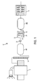
- FIG. 1 is a schematic of a locomotive air supply system that includes an air dryer having a pre-filtration stage with a drain valve to be variably controlled by the present invention
- FIG. 2 is a schematic of a control system for pre-filtration stage and drain valve to be variably controlled according to the present invention
- FIG. 3 is a graph water vapor partial pressure verses ambient temperature for use in controlling the drain valve of a pre-filtration stage according to the present invention.
- FIG. 4 is a flowchart of a process for controlling the drain valve of a pre-filtration stage according to the present invention.
- FIG. 1 a locomotive air system 10 having an air compressor 12 , aftercooler 14 , first and second main reservoirs MR 1 and MR 2 , and an air dryer 16 .
- Second main reservoir is coupled to the braking system 18 and a check valve 20 is positioned between the first and second main reservoirs MR 1 and MR 2 .
- a pre-filtration stage 22 is associated with air dryer 16 and includes a drain valve 24 that is operated according to a variable drain valve purge cycle time that is dependent on actual conditions rather than a predetermined maximum amount of wet air.
- pre-filtration stage 22 further comprises a controller 26 in communication with a temperature sensor 28 , such as a thermistor or thermocouple, which is positioned in or in close proximity to the air stream inlet 30 of air dryer 16 .
- Controller 26 is programmed to receive air temperature information from sensor 28 at inlet 30 to adjust the drain valve purge cycle time, referred to as Time(purge), so that the purge cycle time for drain valve 24 of the water separator and/or coalescer 32 of pre-filtration stage 22 is variably determined based on the air temperature.
- the drain valve purge cycle time is adjusted proportionally to the saturation partial pressure of water vapor in air, as seen in FIG. 3 , based on the actual inlet air temperature.
- controller 26 and pre-filtration stage 22 may be included as part of air dryer 16 , or provided separately as a stand along unit. Controller 26 may also be positioned remotely from pre-filtration stage 22 provided that controller 26 is able to communicate the appropriate change in purge cycle time to pre-filtration stage 22 .
- controller 26 is programmed to implement a purge control process 40 that adjusts the purge cycle time, Time(purge), based on actual conditions.
- the controller system operating parameters 42 of pre-filtration stage 22 are established that will be used to determine any change in the purge cycle timing.
- Operating parameters may include a predetermined minimum reference temperature, T ref , a design reference inlet air temperature, D ref corresponding to a predetermined minimum purge cycle time, Time(purge) min cycle .
- the predetermined minimum reference temperature, T ref represents the lowest temperature at which controller 26 will adjust the purge cycle time and results in a maximum time interval between drain valve actuations.
- the predetermined design reference inlet air temperature is selected based on the temperature that represents the maximum water load, which is a function of air temperature and air flow rate, that is less than the storage volume of pre-filtration stage 22 and less than the amount of water which can be discharged through an open drain valve 24 for a predetermined purge duration, for example 2 seconds, when system 10 is pressurized at the minimum system working pressure.
- the predetermined minimum purge cycle time represents the shortest time interval between subsequent actuations of drain valve 24 .
- the minimum reference temperature, design reference inlet air temperature, and minimum purge cycle time may be set as default values by the manufacturer or user based on the specifications of a particular pre-filtration stage 22 , air dryer 16 , and/or locomotive air system 10 and then loaded into the controller 26 during first step 42 of purge control process 40 .
- the inlet air temperature is sensed 44 , such as by sampling the output of temperature sensor 28 with controller 26 to determine the actual inlet air temperature, T actual .
- Time(purge) min cycle is 2 minutes
- the minimum reference temperature is ⁇ 30° F. with a saturation partial pressure of 0.0062
- the design reference temperature is 100° F. with a saturation partial pressure of 0.9503, at temperatures less than or equal to ⁇ 30° F.
- Time(purge) could be set as the longest purge cycle time allowed by system 10 , and then adjusted downwardly based on the air temperature using an inverse approach to that described above.
- first check 46 and second check 48 may be implemented in a single or any number of computing steps so long as controller 26 applies the appropriate formula to adjust the purge cycle time based on the actual inlet air temperature provided by sensor 28 to account for the actual amount of moisture that may be present in the air.
- Controller 26 may be programmed to receive an input representing when air compressor 12 is being operated to provide compressed air, e.g., an “ON” signal. Controller 26 may be programmed to open drain valve 24 upon detecting that air compressor 12 has been turned on, and then operate drain valve 24 as described above. Similarly, controller 26 can open drain valve 24 when signaled that air compressor 12 has been turned off to completely drain any accumulated water in pre-filtration stage 22 and thus prevent freezing in the event that system 10 is shut down for an extended period in cold temperatures.
- the air dryer may use a humidity sensor in the outlet airstream to determine when the desiccant bed is approaching saturation by monitoring the instantaneous outlet humidity and temperature or other means of dew point dependent desiccant regeneration, such as that disclosed in application NY-1273.
- the air dryer initiates a regeneration cycle.
- the air dryer may be designed so that the regeneration cycle time at some reference operating condition, for example 100° F. and 100% inlet RH and 100 SCFM flow, is known. For example at the reference operating conditions the desiccant bed would become saturated in 2 minutes. If using a humidity sensor in the outlet air stream for control of the regeneration cycle, then under these conditions the outlet air stream humidity would increase to the trigger level in approximately 2 minutes.
- the regeneration cycle time is proportional to the actual conditions of inlet temperature, RH, and air flow, where the total water volume in at those conditions is proportional to the saturation partial pressure of water vapor in air as previously described. Because the air dryer on a locomotive is typically located between MR 1 and MR 2 , the air from the compressor first flows into MR 1 , allowing a significant amount of the aerosol phase water to precipitate out in MR 1 , where it is expelled by the MR 1 spitter valve. Because the desiccant bed becomes saturated with a fixed mass of water reasonably independent of the ambient temperature or rate of air flow, the total water mass flow through the prefiltration is approximately the same as the total water mass removed by the desiccant.
- the prefiltration drain valve may be vented in synchronization with the desiccant regeneration cycle.
Landscapes
- Chemical & Material Sciences (AREA)
- Engineering & Computer Science (AREA)
- Analytical Chemistry (AREA)
- General Chemical & Material Sciences (AREA)
- Oil, Petroleum & Natural Gas (AREA)
- Chemical Kinetics & Catalysis (AREA)
- Transportation (AREA)
- Mechanical Engineering (AREA)
- Valves And Accessory Devices For Braking Systems (AREA)
- Drying Of Gases (AREA)
Abstract
Description
Time(purge)=Time(purge)min cycle×[Saturation Partial Pressure at D ref]/[Saturation Partial Pressure at T ref]
Alternatively, the maximum purge interval may be set explicitly;
Time(purge)=Time(purge)min cycle×[Saturation Partial Pressure at D ref]/[Saturation Partial Pressure at T actual]
Time(purge)=Time(purge)min cycle
Time(purge)=(2 min)×(0.9503)/(0.0062)=306 minutes
Under the same conditions with an inlet air temperature of 70 F, the time between purge cycles will be as follows:
Time(purge)=(2 min)×(0.9503)/(0.3633)=5.2 minutes
Under the same conditions with an inlet air temperature equal to or greater than 100° F., the time between purge cycles will be as follows:
Time(purge)=(2 min)
Claims (13)
Priority Applications (1)
| Application Number | Priority Date | Filing Date | Title |
|---|---|---|---|
| US14/865,902 US9475476B1 (en) | 2015-09-25 | 2015-09-25 | Control of an air dryer drain valve cycle |
Applications Claiming Priority (1)
| Application Number | Priority Date | Filing Date | Title |
|---|---|---|---|
| US14/865,902 US9475476B1 (en) | 2015-09-25 | 2015-09-25 | Control of an air dryer drain valve cycle |
Publications (1)
| Publication Number | Publication Date |
|---|---|
| US9475476B1 true US9475476B1 (en) | 2016-10-25 |
Family
ID=57137607
Family Applications (1)
| Application Number | Title | Priority Date | Filing Date |
|---|---|---|---|
| US14/865,902 Active US9475476B1 (en) | 2015-09-25 | 2015-09-25 | Control of an air dryer drain valve cycle |
Country Status (1)
| Country | Link |
|---|---|
| US (1) | US9475476B1 (en) |
Cited By (6)
| Publication number | Priority date | Publication date | Assignee | Title |
|---|---|---|---|---|
| US9950291B1 (en) | 2016-12-16 | 2018-04-24 | New York Air Brake, LLC | Optimized control of a heater for an air dryer |
| US11058991B2 (en) | 2016-03-23 | 2021-07-13 | New York Air Brake Llc | Adsorption drying unit |
| CN115056759A (en) * | 2022-06-30 | 2022-09-16 | 东风华神汽车有限公司 | Air temperature control system and braking device and vehicle thereof |
| WO2023085436A1 (en) * | 2021-11-15 | 2023-05-19 | ナブテスコオートモーティブ株式会社 | Air supply system, control method for air supply system, and control program for air supply system |
| US11874018B1 (en) | 2020-11-04 | 2024-01-16 | Transaera, Inc. | Cooling and dehumidifcation system |
| US11892192B1 (en) * | 2019-08-22 | 2024-02-06 | Transaera, Inc. | Air conditioning system with multiple energy storage sub-systems |
Citations (9)
| Publication number | Priority date | Publication date | Assignee | Title |
|---|---|---|---|---|
| US5901464A (en) * | 1997-11-26 | 1999-05-11 | Westinghouse Air Brake Company | E-1 twin tower air dryer for an air compressor unit |
| US6276343B1 (en) * | 1998-08-21 | 2001-08-21 | Nissan Motor Co., Ltd. | Leak diagnostic system of evaporative emission control system for internal combustion engines |
| US20080160363A1 (en) * | 2004-07-20 | 2008-07-03 | Akinori Tsukada | Control of the Polymer Humidifying Membrane of a Fuel Cell |
| WO2008130730A1 (en) | 2007-04-17 | 2008-10-30 | New York Air Brake Corporation | Air dryer with pre-filter |
| JP2009154613A (en) | 2007-12-25 | 2009-07-16 | Mitsubishi Fuso Truck & Bus Corp | Compressed air supply device of vehicle |
| US20090188306A1 (en) * | 2007-08-15 | 2009-07-30 | Abb Inc. | Reid vapor pressure analyzer with an air saturator |
| US20100216045A1 (en) * | 2007-08-29 | 2010-08-26 | Toyota Jidosha Kabushiki Kaisha | Fuel cell system and control method thereof |
| US8490991B2 (en) | 2009-01-28 | 2013-07-23 | Continental Teves Ag & Co Ohg | Method for controlling the regeneration cycles for an air dryer in a closed ride control system for vehicles |
| US9283944B2 (en) * | 2014-06-17 | 2016-03-15 | New York Air Brake, LLC | Compressor aftercooler bypass with integral water separator |
-
2015
- 2015-09-25 US US14/865,902 patent/US9475476B1/en active Active
Patent Citations (9)
| Publication number | Priority date | Publication date | Assignee | Title |
|---|---|---|---|---|
| US5901464A (en) * | 1997-11-26 | 1999-05-11 | Westinghouse Air Brake Company | E-1 twin tower air dryer for an air compressor unit |
| US6276343B1 (en) * | 1998-08-21 | 2001-08-21 | Nissan Motor Co., Ltd. | Leak diagnostic system of evaporative emission control system for internal combustion engines |
| US20080160363A1 (en) * | 2004-07-20 | 2008-07-03 | Akinori Tsukada | Control of the Polymer Humidifying Membrane of a Fuel Cell |
| WO2008130730A1 (en) | 2007-04-17 | 2008-10-30 | New York Air Brake Corporation | Air dryer with pre-filter |
| US20090188306A1 (en) * | 2007-08-15 | 2009-07-30 | Abb Inc. | Reid vapor pressure analyzer with an air saturator |
| US20100216045A1 (en) * | 2007-08-29 | 2010-08-26 | Toyota Jidosha Kabushiki Kaisha | Fuel cell system and control method thereof |
| JP2009154613A (en) | 2007-12-25 | 2009-07-16 | Mitsubishi Fuso Truck & Bus Corp | Compressed air supply device of vehicle |
| US8490991B2 (en) | 2009-01-28 | 2013-07-23 | Continental Teves Ag & Co Ohg | Method for controlling the regeneration cycles for an air dryer in a closed ride control system for vehicles |
| US9283944B2 (en) * | 2014-06-17 | 2016-03-15 | New York Air Brake, LLC | Compressor aftercooler bypass with integral water separator |
Non-Patent Citations (1)
| Title |
|---|
| International Search Report Form PCT/ISA/220, International Application No. PCT/US2015/052294, pp. 1-12, Dated May 27, 2016. |
Cited By (10)
| Publication number | Priority date | Publication date | Assignee | Title |
|---|---|---|---|---|
| US11058991B2 (en) | 2016-03-23 | 2021-07-13 | New York Air Brake Llc | Adsorption drying unit |
| US9950291B1 (en) | 2016-12-16 | 2018-04-24 | New York Air Brake, LLC | Optimized control of a heater for an air dryer |
| WO2018111300A1 (en) * | 2016-12-16 | 2018-06-21 | New York Air Brake, LLC | Optimized control of a heater for an air dryer |
| CN110073148A (en) * | 2016-12-16 | 2019-07-30 | 纽约气闸有限公司 | The optimal control of heater for air dryer |
| JP2020504667A (en) * | 2016-12-16 | 2020-02-13 | ニューヨーク・エア・ブレーキ・リミテッド・ライアビリティ・カンパニーNew York Air Brake, Llc | Optimal control of heater in air dryer |
| CN110073148B (en) * | 2016-12-16 | 2020-08-28 | 纽约气闸有限公司 | Optimized control of heater for air dryer |
| US11892192B1 (en) * | 2019-08-22 | 2024-02-06 | Transaera, Inc. | Air conditioning system with multiple energy storage sub-systems |
| US11874018B1 (en) | 2020-11-04 | 2024-01-16 | Transaera, Inc. | Cooling and dehumidifcation system |
| WO2023085436A1 (en) * | 2021-11-15 | 2023-05-19 | ナブテスコオートモーティブ株式会社 | Air supply system, control method for air supply system, and control program for air supply system |
| CN115056759A (en) * | 2022-06-30 | 2022-09-16 | 东风华神汽车有限公司 | Air temperature control system and braking device and vehicle thereof |
Similar Documents
| Publication | Publication Date | Title |
|---|---|---|
| US9475476B1 (en) | Control of an air dryer drain valve cycle | |
| CA2999837C (en) | Improved control of an air dryer drain valve cycle | |
| US10150077B2 (en) | Air dryer control using humidity | |
| US10598299B2 (en) | Heater control for an air dryer | |
| US9864382B2 (en) | Smart heater control for an air dryer | |
| US9950291B1 (en) | Optimized control of a heater for an air dryer | |
| AU2018253576B2 (en) | Heater control for an air dryer | |
| US10023169B2 (en) | Sleep mode for an air dryer | |
| CA2959300C (en) | Improved control of an air dryer regeneration cycle | |
| US9644893B2 (en) | Control of an air dryer regeneration cycle | |
| AU2015409682B2 (en) | Sleep mode for an air dryer |
Legal Events
| Date | Code | Title | Description |
|---|---|---|---|
| AS | Assignment |
Owner name: NEW YORK AIR BRAKE, LLC, NEW YORK Free format text: ASSIGNMENT OF ASSIGNORS INTEREST;ASSIGNOR:WRIGHT, ERIC C;REEL/FRAME:036839/0945 Effective date: 20150925 |
|
| STCF | Information on status: patent grant |
Free format text: PATENTED CASE |
|
| MAFP | Maintenance fee payment |
Free format text: PAYMENT OF MAINTENANCE FEE, 4TH YEAR, LARGE ENTITY (ORIGINAL EVENT CODE: M1551); ENTITY STATUS OF PATENT OWNER: LARGE ENTITY Year of fee payment: 4 |
|
| MAFP | Maintenance fee payment |
Free format text: PAYMENT OF MAINTENANCE FEE, 8TH YEAR, LARGE ENTITY (ORIGINAL EVENT CODE: M1552); ENTITY STATUS OF PATENT OWNER: LARGE ENTITY Year of fee payment: 8 |