US9458726B2 - Dovetail retention system for blade tracks - Google Patents
Dovetail retention system for blade tracks Download PDFInfo
- Publication number
- US9458726B2 US9458726B2 US14/094,316 US201314094316A US9458726B2 US 9458726 B2 US9458726 B2 US 9458726B2 US 201314094316 A US201314094316 A US 201314094316A US 9458726 B2 US9458726 B2 US 9458726B2
- Authority
- US
- United States
- Prior art keywords
- turbine shroud
- inner carrier
- segment
- dovetail post
- blade track
- Prior art date
- Legal status (The legal status is an assumption and is not a legal conclusion. Google has not performed a legal analysis and makes no representation as to the accuracy of the status listed.)
- Expired - Fee Related, expires
Links
Images


Classifications
-
- F—MECHANICAL ENGINEERING; LIGHTING; HEATING; WEAPONS; BLASTING
- F01—MACHINES OR ENGINES IN GENERAL; ENGINE PLANTS IN GENERAL; STEAM ENGINES
- F01D—NON-POSITIVE DISPLACEMENT MACHINES OR ENGINES, e.g. STEAM TURBINES
- F01D5/00—Blades; Blade-carrying members; Heating, heat-insulating, cooling or antivibration means on the blades or the members
- F01D5/12—Blades
- F01D5/22—Blade-to-blade connections, e.g. for damping vibrations
- F01D5/225—Blade-to-blade connections, e.g. for damping vibrations by shrouding
-
- F—MECHANICAL ENGINEERING; LIGHTING; HEATING; WEAPONS; BLASTING
- F01—MACHINES OR ENGINES IN GENERAL; ENGINE PLANTS IN GENERAL; STEAM ENGINES
- F01D—NON-POSITIVE DISPLACEMENT MACHINES OR ENGINES, e.g. STEAM TURBINES
- F01D11/00—Preventing or minimising internal leakage of working-fluid, e.g. between stages
- F01D11/08—Preventing or minimising internal leakage of working-fluid, e.g. between stages for sealing space between rotor blade tips and stator
-
- F—MECHANICAL ENGINEERING; LIGHTING; HEATING; WEAPONS; BLASTING
- F01—MACHINES OR ENGINES IN GENERAL; ENGINE PLANTS IN GENERAL; STEAM ENGINES
- F01D—NON-POSITIVE DISPLACEMENT MACHINES OR ENGINES, e.g. STEAM TURBINES
- F01D5/00—Blades; Blade-carrying members; Heating, heat-insulating, cooling or antivibration means on the blades or the members
- F01D5/12—Blades
- F01D5/14—Form or construction
- F01D5/147—Construction, i.e. structural features, e.g. of weight-saving hollow blades
-
- F—MECHANICAL ENGINEERING; LIGHTING; HEATING; WEAPONS; BLASTING
- F05—INDEXING SCHEMES RELATING TO ENGINES OR PUMPS IN VARIOUS SUBCLASSES OF CLASSES F01-F04
- F05D—INDEXING SCHEME FOR ASPECTS RELATING TO NON-POSITIVE-DISPLACEMENT MACHINES OR ENGINES, GAS-TURBINES OR JET-PROPULSION PLANTS
- F05D2240/00—Components
- F05D2240/10—Stators
- F05D2240/11—Shroud seal segments
-
- F—MECHANICAL ENGINEERING; LIGHTING; HEATING; WEAPONS; BLASTING
- F05—INDEXING SCHEMES RELATING TO ENGINES OR PUMPS IN VARIOUS SUBCLASSES OF CLASSES F01-F04
- F05D—INDEXING SCHEME FOR ASPECTS RELATING TO NON-POSITIVE-DISPLACEMENT MACHINES OR ENGINES, GAS-TURBINES OR JET-PROPULSION PLANTS
- F05D2260/00—Function
- F05D2260/30—Retaining components in desired mutual position
-
- F—MECHANICAL ENGINEERING; LIGHTING; HEATING; WEAPONS; BLASTING
- F05—INDEXING SCHEMES RELATING TO ENGINES OR PUMPS IN VARIOUS SUBCLASSES OF CLASSES F01-F04
- F05D—INDEXING SCHEME FOR ASPECTS RELATING TO NON-POSITIVE-DISPLACEMENT MACHINES OR ENGINES, GAS-TURBINES OR JET-PROPULSION PLANTS
- F05D2300/00—Materials; Properties thereof
- F05D2300/60—Properties or characteristics given to material by treatment or manufacturing
- F05D2300/603—Composites; e.g. fibre-reinforced
- F05D2300/6033—Ceramic matrix composites [CMC]
-
- Y—GENERAL TAGGING OF NEW TECHNOLOGICAL DEVELOPMENTS; GENERAL TAGGING OF CROSS-SECTIONAL TECHNOLOGIES SPANNING OVER SEVERAL SECTIONS OF THE IPC; TECHNICAL SUBJECTS COVERED BY FORMER USPC CROSS-REFERENCE ART COLLECTIONS [XRACs] AND DIGESTS
- Y02—TECHNOLOGIES OR APPLICATIONS FOR MITIGATION OR ADAPTATION AGAINST CLIMATE CHANGE
- Y02T—CLIMATE CHANGE MITIGATION TECHNOLOGIES RELATED TO TRANSPORTATION
- Y02T50/00—Aeronautics or air transport
- Y02T50/60—Efficient propulsion technologies, e.g. for aircraft
-
- Y02T50/672—
-
- Y—GENERAL TAGGING OF NEW TECHNOLOGICAL DEVELOPMENTS; GENERAL TAGGING OF CROSS-SECTIONAL TECHNOLOGIES SPANNING OVER SEVERAL SECTIONS OF THE IPC; TECHNICAL SUBJECTS COVERED BY FORMER USPC CROSS-REFERENCE ART COLLECTIONS [XRACs] AND DIGESTS
- Y10—TECHNICAL SUBJECTS COVERED BY FORMER USPC
- Y10T—TECHNICAL SUBJECTS COVERED BY FORMER US CLASSIFICATION
- Y10T29/00—Metal working
- Y10T29/49—Method of mechanical manufacture
- Y10T29/49316—Impeller making
- Y10T29/4932—Turbomachine making
Definitions
- the present disclosure relates generally to gas turbine engines, and more specifically to turbine shrouds used in gas turbine engines.
- Gas turbine engines are used to power aircraft, watercraft, power generators, and the like.
- Gas turbine engines typically include a compressor, a combustor, and a turbine.
- the compressor compresses air drawn into the engine and delivers high pressure air to the combustor.
- fuel is mixed with the high pressure air and is ignited.
- Products of the combustion reaction in the combustor are directed into the turbine where work is extracted to drive the compressor and, sometimes, an output shaft, fan, or propeller. Left-over products of the combustion are exhausted out of the turbine and may provide thrust in some applications.
- Compressors and turbines typically include alternating stages of static vane assemblies and rotating wheel assemblies.
- the rotating wheel assemblies include disks carrying blades around their outer edges. When the rotating wheel assemblies turn, tips of the blades move along blade tracks included in static shrouds that are arranged around the rotating wheel assemblies.
- static shrouds may be coupled to an engine case that surrounds the compressor, the combustor, and the turbine.
- Some shrouds positioned in the turbine may be exposed to high temperatures from products of the combustion reaction in the combustor.
- Such shrouds sometimes include components made from materials that have different coefficients of thermal expansion. Due to the differing coefficients of thermal expansion, the components of some turbine shrouds expand at different rates when exposed to combustion products. For example, coupling such components with traditional fasteners such as rivets or bolts may not allow for the differing levels of expansion and contraction during operation of the gas turbine engine.
- a turbine shroud for use in the turbine section of a gas turbine engine is disclosed in this paper.
- the turbine shroud is adapted to extend around a rotatable turbine wheel assembly having a wheel and blades.
- the turbine shroud blocks hot gasses flowing through the turbine section from passing over the blades without pushing the blades. By ensuring that the hot gasses push the blades, the turbine shroud helps cause the turbine wheel assembly to rotate when hot gasses are driven through the turbine section from a combustion section of the gas turbine engine. Rotation of the turbine wheel assembly can then be used to drive a compressor, a fan, a propeller, a generator, or other modules coupled to the turbine wheel assembly.
- the turbine shroud disclosed includes a metallic support ring and a ceramic blade track.
- the metallic support ring is adapted to be coupled to other metallic components of the turbine section to hold the turbine shroud in place relative to the rest of the turbine section.
- the ceramic blade track is illustratively made up of a plurality of ceramic blade track segments manufactured from a ceramic matrix composite material adapted to withstand high temperatures.
- the plurality of ceramic blade track segments are arranged to form a hoop around the turbine wheel assembly so that the ceramic blade track is positioned radially between the metallic support ring and the turbine wheel assembly.
- the position of the ceramic blade track insulates the metallic support ring from the hot gasses directed at the blades of the turbine wheel assembly.
- the turbine shroud also includes a plurality of segment retainers adapted to hold each of the plurality of ceramic blade track segments in place relative to the metallic support ring while allowing the metallic support ring and the ceramic segments of the blade track to expand and contract at different rates based on temperature.
- the metallic support ring has a metallic inner carrier formed to include a plurality of apertures.
- the plurality of ceramic blade track segments each includes an arcuate runner arranged radially inward from the metallic inner carrier and at least one dovetail post extending radially outward from the arcuate runner through one of the apertures formed in the metallic inner carrier.
- the plurality of segment retainers mate with the dovetail posts of each ceramic blade track segment so that the plurality of ceramic blade track segments are coupled to the metallic inner carrier.
- FIG. 1 is a cut-away perspective view of a gas turbine engine
- FIG. 2 is a partial cross-sectional view of the gas turbine engine of FIG. 1 showing the arrangement of a turbine shroud in the gas turbine engine;
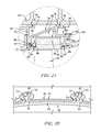
- FIG. 2A is a detail cross-sectional view showing a portion of FIG. 2 ;
- FIG. 2B is another detail cross-sectional view taken along line 2 B- 2 B shown in FIG. 2 ;
- FIG. 3 is an exploded perspective view of a segment of the turbine shroud shown in FIG. 2 showing that the turbine shroud includes a blade track segment with axially-extending dovetail posts, an inner carrier segment, a plurality of segment retainers, a clip segment, and an outer carrier segment;
- FIG. 4 is a partial cross-sectional view of another gas turbine engine showing the arrangement of another turbine shroud in the gas turbine engine;
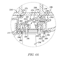
- FIG. 4A is a detail cross-sectional view showing a portion of FIG. 4 ;
- FIG. 5 is an exploded perspective view of a section of the turbine shroud shown in FIG. 4 .
- FIG. 1 is an illustrative aerospace gas turbine engine 10 cut-away to show that the engine 10 includes a fan 12 , a compressor 14 , a combustor 16 , and a turbine 18 all mounted to a case 20 .
- the fan 12 is driven by the turbine 18 and provides thrust for propelling an air vehicle (not shown).
- the compressor 14 is configured compress and deliver air to the combustor 16 .
- the combustor 16 is configured to mix fuel with the compressed air received from the compressor 14 and to ignite the fuel.
- the hot high pressure products of the combustion reaction in the combustor 16 are directed into the turbine 18 and the turbine 18 extracts work to drive the compressor 14 and the fan 12 .
- each vane assembly 21 , 22 includes a plurality corresponding of vanes 31 , 32 and the turbine wheel assembly 26 includes a plurality of corresponding blades 36 .
- the vanes 31 of the vane assembly 21 extend across the flow path of the hot, high-pressure combustion products from the combustor 16 to direct the combustion products toward the blades 36 of the turbine wheel assembly 26 .
- the blades 36 are in turn pushed by the combustion products to cause the turbine wheel assembly 26 to rotate; thereby, driving the rotating components of the compressor 14 and the fan 12 .
- the turbine 18 also includes a turbine shroud 46 that extends around turbine wheel assembly 26 to block combustion products from passing over the blades 36 without pushing the blades 36 to rotate as shown in FIG. 2 . Combustion products that are allowed to pass over the blades 36 do not push the blades 36 and such passed-over products contribute to lost performance within the engine 10 .
- the turbine shroud 46 illustratively includes a metallic support ring 48 , a ceramic blade track (sometimes called seal ring) 50 , and a plurality of metallic segment retainers 52 as shown in FIGS. 2, 2A, and 2B .
- the support ring 48 is coupled to the case 20 and extends inwardly in a radial direction from the case 20 toward the turbine wheel assembly 26 .
- the blade track 50 is coupled to the support ring 48 by the segment retainers 52 and is supported by the support ring 48 in position adjacent to the blades 36 of the turbine wheel assembly 26 so that the blades 36 run along the blade track 50 .
- the support ring 48 is an annular component including an outer carrier 54 and an inner carrier 56 as shown in FIGS. 2 and 2A .
- the outer carrier 48 is coupled to the inner carrier 50 by a clip 58 that is deformed to clamp down on both the outer carrier 48 and the inner carrier 50 .
- the outer carrier 54 is made up of a plurality of outer carrier segments 55 and is coupled to the case 20 .
- the inner carrier 56 is made up of a plurality of inner carrier segments 57 each coupled to a corresponding outer carrier segment 55 .
- the clip 58 is also made up of a plurality clip segments 59 with a C-shaped cross-section that forms a forward facing channel 71 .
- the outer carrier 54 , the inner carrier 56 , and the clip 58 may each be monolithic components rather than segmented components.
- the blade track 50 is made up of a plurality of blade track segments 51 , one of which is shown in FIG. 3 .
- Each of the blade track segments 51 is coupled to a corresponding outer carrier segment 55 and an inner carrier segment 57 by two of the segment retainers 52 to support the blade track segment 51 in position adjacent to the blades 36 of the turbine wheel assembly 26 as shown in FIG. 2 .
- the blade track segments 51 are each made from a ceramic material; and, more particularly, a ceramic matrix composite (CMC).
- CMC ceramic matrix composite
- other ceramic materials are contemplated.
- a ceramic material is any monolithic ceramic or composite in which at least one constituent is a ceramic.
- the blade track segments 51 may be made of other metallic, non-metallic, or composite materials.
- segments 51 , 55 , 57 , 59 of the blade track 50 , the outer carrier 54 , the inner carrier 56 , and the clip 58 are shown along with two segment retainers 52 and two locating keys 60 .
- Each of the segments 51 , 55 , 57 , 59 are repeated to provide the fully annular turbine shroud 46 .
- Each blade track segment 51 includes an arcuate runner 65 , a first dovetail post 61 , and a second dovetail post 62 as shown in FIG. 3 .
- the arcuate runner 65 is located adjacent to the blades 36 of the turbine wheel assembly 26 so that the blades 36 move along an inner radial face 66 of the arcuate runner 65 .
- the dovetail posts 61 , 62 are coupled to an outer radial face 68 of the arcuate runner 65 and are spaced radially from one another as shown in FIG. 3 .
- Each of the dovetail posts 61 , 62 includes a body 70 and a head 72 as shown in FIG. 3 .
- the body 70 of each dovetail post 61 , 62 extends outward in the radial direction from the arcuate runner 65 and axially along the arcuate runner 65 .
- the head 72 of each dovetail post extends circumferentially in both directions from the body 70 so that the head 72 can be captured by the segment retainers 52 when the turbine shroud 46 is assembled as shown in FIG. 2B .
- Each of the outer carrier segments 55 includes a forward connection portion 74 , an aft connection portion 76 , and an intermediate portion 78 extending axially from the forward connection portion 74 to the aft connection portion 76 as shown in FIG. 3 .
- the forward connection portion 74 includes outer hangers 75 for connecting the outer carrier 54 to the case 20 and inner hangers 77 for connecting the outer carrier 54 to a forward portion of the blade track 50 .
- the aft connection portion 76 includes an outer hanger 79 for connecting the outer carrier 54 to the case 20 and an aft flange 80 for connecting the outer carrier 54 to the inner carrier 56 via the clip 58 as shown in FIG. 2A .
- Each of the inner carrier segments 57 includes an arcuate plate 82 , a forward seal carrier 84 , an aft seal carrier 86 , and an aft flange 90 as shown in FIGS. 2 and 3 .
- the arcuate plate 82 is formed to include apertures 91 , 92 sized and arranged to receive the dovetail posts 61 , 62 of the corresponding blade track segment 51 as shown in FIGS. 2A and 2B .
- the forward seal carrier 84 is spaced forward in the axial direction from the apertures 91 , 92 and extends inward in the radial direction from the plate 82 .
- the aft seal carrier 86 is spaced aft in the axial direction from the apertures 91 , 92 and extends inward in the radial direction from the plate 82 .
- Each seal carrier 84 , 86 forms a corresponding seal receiving channel 85 , 87 extending circumferentially along the plate 82 and sized to receive rope seals 88 , 89 as shown in FIG. 2A .
- the aft flange 90 is coupled to the aft flange 80 of the outer carrier segment 55 via the clip 58 as shown in FIG. 2A .
- the outer carrier 54 and the inner carrier 56 cooperate to form an annular cavity 98 as shown in FIG. 2A .
- the heads 72 and the segment retainers 52 are arranged in the annular cavity 98 when the turbine shroud 46 is assembled.
- Each segment retainer 52 is illustratively C-shaped forming a retention channel 94 sized and arranged to receive the head 72 of one of the dovetail posts 62 , 64 as shown in FIGS. 2A and 3 . Further, each segment retainer 52 is sized to block the heads 72 of the dovetail posts 61 , 62 from moving through the apertures 91 , 92 of the inner retainer 56 when the segment retainers 52 are coupled to the dovetail posts 61 , 62 as shown in FIG. 2B . In other embodiments, the segment retainers 52 may be coupled to or incorporated into the inner carrier segments 57 and the apertures 91 , 92 of the inner carrier segments 57 may be slots extending from an edge of the inner carrier segment 57 .
- the arrangement of the dovetail retention system formed by the blade track segments 51 , the segment retainers 52 , and the inner carrier segments 57 may be reversed.
- the segment retainers 52 may be incorporated into the blade track segments 51 in place of the dovetail posts 61 , 62 .
- the dovetail posts 61 , 62 may be attached to plates and may extend through the apertures formed in the inner carrier segments 57 to allow mating of the dovetail posts 61 , 62 with the segment retainers 52 .
- the locating keys 60 are configured to locate circumferentially the inner carrier segments 57 relative to the outer carrier segments 55 when the turbine shroud 46 is assembled.
- the aft flange 80 of the outer carrier segment 55 is formed to include holes 95 sized to receive the locating keys 60 as shown in FIG. 3 .
- the aft flange 90 of the inner carrier segment 57 is formed to include notches 96 sized to receive a portion of the locating keys 60 . When assembled, the locating keys 60 extend through the holes 95 and into the notches 96 to locate the inner carrier segments 57 relative to the outer carrier segments 55 .
- the blade track segment 51 is first coupled to the inner carrier segment 57 by the segment retainers 52 .
- the dovetail posts 61 , 62 of a blade track segment 51 are radially inserted through the apertures 91 , 92 formed in the inner carrier segment 57 as shown in FIGS. 2, 2A, and 2B .
- segment retainers 52 are slid over the heads 72 of the dovetail posts 61 , 62 so that the heads of the dovetail posts 61 , 62 are received in the retention channels 94 of a segment retainer 52 .
- the outer carrier segment 55 is located circumferentially relative to the inner carrier segment 57 .
- the outer carrier segment 55 is placed over the inner carrier segment 57 with holes 95 formed in the aft flange 80 of the outer carrier segment 55 aligned with notches 96 formed in the aft flange 90 of the inner carrier segment 57 .
- locating keys 60 are inserted through holes 95 are into notches 96 .
- the outer carrier segment 55 is coupled to the inner carrier segment 57 .
- the clip segment 59 is slid over the aft flanges 80 , 90 included in the outer carrier segment 55 and the inner carrier segment 57 , respectively, so that the aft flanges 80 , 90 are received in the channel 71 formed by the clip segment 59 .
- the clip segment 59 is then deformed or crimped to engage the aft flanges 80 , 90 coupling the outer carrier segment 55 and the inner carrier segment 57 .
- FIGS. 4-5 Another illustrative turbine shroud 246 is shown in FIGS. 4-5 .
- the turbine shroud 246 is configured for use in engine 10 and is substantially similar to the turbine shroud 46 shown in FIGS. 1-4 and described herein. Accordingly, similar reference numbers in the 200 series indicate features that are common between the turbine shroud 46 and the turbine shroud 246 .
- the method of assembling the turbine shroud 246 is similar to the method of assembling the turbine shroud 46 described herein.
- the description of the engine 10 and the turbine shroud 46 and its method of assembly are hereby incorporated by reference to apply to the turbine shroud 246 , except in instances when it conflicts with the specific description and drawings of the turbine shroud 246 .
- the dovetail posts 261 , 262 that are coupled to the arcuate runner 265 are spaced axially from one another as shown in FIG. 5 .
- the body 270 of each dovetail post 261 , 262 extends circumferentially along the arcuate runner 265 .
- the head 272 of each dovetail post extends axially in both directions from the body 270 as shown in FIG. 3A .
- the heads 272 of each dovetail post 261 , 262 is flat, or tangent, to the outer radial surface of the runner 265 .
- the heads 272 of each dovetail post 261 , 262 are arcuate and spaced a consistent distance from the runner 265 .
- the arcuate plate 282 is formed to include apertures 291 , 292 that extend circumferentially as shown in FIG. 5 to receive the dovetail posts 261 , 262 of the corresponding blade track segment 251 as shown in FIG. 5 .
- the aft flanges 280 , 290 of the outer carrier 254 and the inner carrier 256 are coupled via a bird mouth and hanger arrangement as shown in FIGS. 4 and 4A . More specifically, the aft flange 280 of the outer carrier 254 forms a rearwardly-opening channel that receives the aft flange 290 as shown in FIGS. 4 and 4A .
Landscapes
- Engineering & Computer Science (AREA)
- Mechanical Engineering (AREA)
- General Engineering & Computer Science (AREA)
- Architecture (AREA)
- Turbine Rotor Nozzle Sealing (AREA)
Abstract
Description
Claims (20)
Priority Applications (1)
| Application Number | Priority Date | Filing Date | Title |
|---|---|---|---|
| US14/094,316 US9458726B2 (en) | 2013-03-13 | 2013-12-02 | Dovetail retention system for blade tracks |
Applications Claiming Priority (2)
| Application Number | Priority Date | Filing Date | Title |
|---|---|---|---|
| US201361779534P | 2013-03-13 | 2013-03-13 | |
| US14/094,316 US9458726B2 (en) | 2013-03-13 | 2013-12-02 | Dovetail retention system for blade tracks |
Publications (2)
| Publication Number | Publication Date |
|---|---|
| US20150044049A1 US20150044049A1 (en) | 2015-02-12 |
| US9458726B2 true US9458726B2 (en) | 2016-10-04 |
Family
ID=50896485
Family Applications (1)
| Application Number | Title | Priority Date | Filing Date |
|---|---|---|---|
| US14/094,316 Expired - Fee Related US9458726B2 (en) | 2013-03-13 | 2013-12-02 | Dovetail retention system for blade tracks |
Country Status (3)
| Country | Link |
|---|---|
| US (1) | US9458726B2 (en) |
| EP (1) | EP2971588A1 (en) |
| WO (1) | WO2014163674A1 (en) |
Cited By (21)
| Publication number | Priority date | Publication date | Assignee | Title |
|---|---|---|---|---|
| US20160146053A1 (en) * | 2014-11-25 | 2016-05-26 | United Technologies Corporation | Blade outer air seal support structure |
| US10280801B2 (en) * | 2017-06-15 | 2019-05-07 | General Electric Company | Turbine component and turbine shroud assembly |
| US10358922B2 (en) | 2016-11-10 | 2019-07-23 | Rolls-Royce Corporation | Turbine wheel with circumferentially-installed inter-blade heat shields |
| US20190284947A1 (en) * | 2018-03-14 | 2019-09-19 | General Electric Company | Cmc shroud segment with interlocking mechanical joints and fabrication |
| US10443616B2 (en) * | 2016-03-16 | 2019-10-15 | United Technologies Corporation | Blade outer air seal with centrally mounted seal arc segments |
| US20190360351A1 (en) * | 2018-05-22 | 2019-11-28 | Rolls-Royce Corporation | Tapered abradable coatings |
| US10704407B2 (en) | 2017-04-21 | 2020-07-07 | Rolls-Royce High Temperature Composites Inc. | Ceramic matrix composite blade track segments |
| US10858950B2 (en) | 2017-07-27 | 2020-12-08 | Rolls-Royce North America Technologies, Inc. | Multilayer abradable coatings for high-performance systems |
| US20210017871A1 (en) * | 2019-07-19 | 2021-01-21 | United Technologies Corporation | Cmc boas arrangement |
| US10900371B2 (en) | 2017-07-27 | 2021-01-26 | Rolls-Royce North American Technologies, Inc. | Abradable coatings for high-performance systems |
| US10907487B2 (en) | 2018-10-16 | 2021-02-02 | Honeywell International Inc. | Turbine shroud assemblies for gas turbine engines |
| US10989060B2 (en) * | 2015-05-26 | 2021-04-27 | Rolls-Royce North American Technologies Inc. | Ceramic matrix composite seal segment for a gas turbine engine |
| US11015485B2 (en) | 2019-04-17 | 2021-05-25 | Rolls-Royce Corporation | Seal ring for turbine shroud in gas turbine engine with arch-style support |
| US11073038B2 (en) | 2019-07-19 | 2021-07-27 | Raytheon Technologies Corporation | CMC BOAS arrangement |
| US11105214B2 (en) | 2019-07-19 | 2021-08-31 | Raytheon Technologies Corporation | CMC BOAS arrangement |
| US11111796B1 (en) | 2020-05-18 | 2021-09-07 | Rolls-Royce North American Technologies Inc. | Turbine shroud assembly with dovetail retention system |
| US11230937B2 (en) | 2020-05-18 | 2022-01-25 | Rolls-Royce North American Technologies Inc. | Turbine shroud assembly with dovetail retention system |
| US11248482B2 (en) | 2019-07-19 | 2022-02-15 | Raytheon Technologies Corporation | CMC BOAS arrangement |
| US11286801B2 (en) * | 2018-10-12 | 2022-03-29 | Raytheon Technologies Corporation | Boas with twin axial dovetail |
| US11434785B2 (en) * | 2018-06-28 | 2022-09-06 | MTU Aero Engines AG | Jacket ring assembly for a turbomachine |
| US11761343B2 (en) | 2019-03-13 | 2023-09-19 | Rtx Corporation | BOAS carrier with dovetail attachments |
Families Citing this family (29)
| Publication number | Priority date | Publication date | Assignee | Title |
|---|---|---|---|---|
| EP2951399B1 (en) | 2013-01-29 | 2020-02-19 | Rolls-Royce Corporation | Turbine shroud and corresponding assembly method |
| EP2971577B1 (en) | 2013-03-13 | 2018-08-29 | Rolls-Royce Corporation | Turbine shroud |
| US9506356B2 (en) * | 2013-03-15 | 2016-11-29 | Rolls-Royce North American Technologies, Inc. | Composite retention feature |
| US10190434B2 (en) | 2014-10-29 | 2019-01-29 | Rolls-Royce North American Technologies Inc. | Turbine shroud with locating inserts |
| CA2915370A1 (en) | 2014-12-23 | 2016-06-23 | Rolls-Royce Corporation | Full hoop blade track with axially keyed features |
| CA2915246A1 (en) * | 2014-12-23 | 2016-06-23 | Rolls-Royce Corporation | Turbine shroud |
| US10941942B2 (en) | 2014-12-31 | 2021-03-09 | Rolls-Royce North American Technologies Inc. | Retention system for gas turbine engine assemblies |
| EP3045674B1 (en) | 2015-01-15 | 2018-11-21 | Rolls-Royce Corporation | Turbine shroud with tubular runner-locating inserts |
| US10100649B2 (en) | 2015-03-31 | 2018-10-16 | Rolls-Royce North American Technologies Inc. | Compliant rail hanger |
| CA2925588A1 (en) | 2015-04-29 | 2016-10-29 | Rolls-Royce Corporation | Brazed blade track for a gas turbine engine |
| CA2924866A1 (en) | 2015-04-29 | 2016-10-29 | Daniel K. Vetters | Composite keystoned blade track |
| US10550709B2 (en) | 2015-04-30 | 2020-02-04 | Rolls-Royce North American Technologies Inc. | Full hoop blade track with flanged segments |
| US9963990B2 (en) * | 2015-05-26 | 2018-05-08 | Rolls-Royce North American Technologies, Inc. | Ceramic matrix composite seal segment for a gas turbine engine |
| US10087770B2 (en) * | 2015-05-26 | 2018-10-02 | Rolls-Royce Corporation | Shroud cartridge having a ceramic matrix composite seal segment |
| US10030541B2 (en) | 2015-07-01 | 2018-07-24 | Rolls-Royce North American Technologies Inc. | Turbine shroud with clamped flange attachment |
| US10240476B2 (en) | 2016-01-19 | 2019-03-26 | Rolls-Royce North American Technologies Inc. | Full hoop blade track with interstage cooling air |
| US10563531B2 (en) * | 2016-03-16 | 2020-02-18 | United Technologies Corporation | Seal assembly for gas turbine engine |
| US10436071B2 (en) | 2016-04-15 | 2019-10-08 | United Technologies Corporation | Blade outer air seal having retention snap ring |
| US10287906B2 (en) | 2016-05-24 | 2019-05-14 | Rolls-Royce North American Technologies Inc. | Turbine shroud with full hoop ceramic matrix composite blade track and seal system |
| US10415415B2 (en) | 2016-07-22 | 2019-09-17 | Rolls-Royce North American Technologies Inc. | Turbine shroud with forward case and full hoop blade track |
| US20180149030A1 (en) * | 2016-11-30 | 2018-05-31 | Rolls-Royce Corporation | Turbine shroud with hanger attachment |
| US10577951B2 (en) * | 2016-11-30 | 2020-03-03 | Rolls-Royce North American Technologies Inc. | Gas turbine engine with dovetail connection having contoured root |
| FR3065481B1 (en) * | 2017-04-19 | 2020-07-17 | Safran Aircraft Engines | TURBINE ASSEMBLY, PARTICULARLY FOR A TURBOMACHINE |
| CA3000376A1 (en) | 2017-05-23 | 2018-11-23 | Rolls-Royce Corporation | Turbine shroud assembly having ceramic matrix composite track segments with metallic attachment features |
| US10738628B2 (en) * | 2018-05-25 | 2020-08-11 | General Electric Company | Joint for band features on turbine nozzle and fabrication |
| US20200072070A1 (en) * | 2018-09-05 | 2020-03-05 | United Technologies Corporation | Unified boas support and vane platform |
| US10634010B2 (en) | 2018-09-05 | 2020-04-28 | United Technologies Corporation | CMC BOAS axial retaining clip |
| US11220925B2 (en) * | 2019-10-10 | 2022-01-11 | Rolls-Royce North American Technologies Inc. | Turbine shroud with friction mounted ceramic matrix composite blade track |
| US11746658B2 (en) * | 2020-10-20 | 2023-09-05 | Rolls-Royce Corporation | Turbine shroud with containment features |
Citations (41)
| Publication number | Priority date | Publication date | Assignee | Title |
|---|---|---|---|---|
| US3813185A (en) * | 1971-06-29 | 1974-05-28 | Snecma | Support structure for rotor blades of turbo-machines |
| GB1487064A (en) | 1974-08-23 | 1977-09-28 | Rolls Royce | Wall structure for hot fluid streams |
| US4087199A (en) | 1976-11-22 | 1978-05-02 | General Electric Company | Ceramic turbine shroud assembly |
| US4460311A (en) * | 1980-05-24 | 1984-07-17 | MTU Motogren-Und Turbinen-Union | Apparatus for minimizing and maintaining constant the blade tip clearance of axial-flow turbines in gas turbine engines |
| US4512159A (en) | 1984-04-02 | 1985-04-23 | United Technologies Corporation | Clip attachment |
| US4728257A (en) | 1986-06-18 | 1988-03-01 | The United States Of America As Represented By The Administrator Of The National Aeronautics And Space Administration | Thermal stress minimized, two component, turbine shroud seal |
| JPH0326346U (en) | 1989-07-19 | 1991-03-18 | ||
| US5074752A (en) | 1990-08-06 | 1991-12-24 | General Electric Company | Gas turbine outlet guide vane mounting assembly |
| US5080556A (en) * | 1990-09-28 | 1992-01-14 | General Electric Company | Thermal seal for a gas turbine spacer disc |
| JP3026346U (en) | 1995-12-27 | 1996-07-12 | 株式会社ヨーヅリ | Shock absorber |
| JPH10205305A (en) | 1997-01-20 | 1998-08-04 | Mitsubishi Heavy Ind Ltd | Stationary blade ring |
| US6406256B1 (en) | 1999-08-12 | 2002-06-18 | Alstom | Device and method for the controlled setting of the gap between the stator arrangement and rotor arrangement of a turbomachine |
| US20030185674A1 (en) | 2002-03-28 | 2003-10-02 | General Electric Company | Shroud segment and assembly for a turbine engine |
| US6648597B1 (en) | 2002-05-31 | 2003-11-18 | Siemens Westinghouse Power Corporation | Ceramic matrix composite turbine vane |
| US6702550B2 (en) | 2002-01-16 | 2004-03-09 | General Electric Company | Turbine shroud segment and shroud assembly |
| US6758653B2 (en) | 2002-09-09 | 2004-07-06 | Siemens Westinghouse Power Corporation | Ceramic matrix composite component for a gas turbine engine |
| US6896483B2 (en) | 2001-07-02 | 2005-05-24 | Allison Advanced Development Company | Blade track assembly |
| US7052235B2 (en) | 2004-06-08 | 2006-05-30 | General Electric Company | Turbine engine shroud segment, hanger and assembly |
| US7117983B2 (en) | 2003-11-04 | 2006-10-10 | General Electric Company | Support apparatus and method for ceramic matrix composite turbine bucket shroud |
| US7278820B2 (en) | 2005-10-04 | 2007-10-09 | Siemens Power Generation, Inc. | Ring seal system with reduced cooling requirements |
| US7284958B2 (en) | 2003-03-22 | 2007-10-23 | Allison Advanced Development Company | Separable blade platform |
| US7306826B2 (en) | 2004-02-23 | 2007-12-11 | General Electric Company | Use of biased fabric to improve properties of SiC/SiC ceramic composites for turbine engine components |
| US7329101B2 (en) | 2004-12-29 | 2008-02-12 | General Electric Company | Ceramic composite with integrated compliance/wear layer |
| US20080159850A1 (en) | 2007-01-03 | 2008-07-03 | United Technologies Corporation | Replaceable blade outer air seal design |
| US7488157B2 (en) | 2006-07-27 | 2009-02-10 | Siemens Energy, Inc. | Turbine vane with removable platform inserts |
| EP2034132A2 (en) | 2007-09-06 | 2009-03-11 | United Technologies Corporation | Shroud segment with seal and corresponding manufacturing method |
| US7510379B2 (en) | 2005-12-22 | 2009-03-31 | General Electric Company | Composite blading member and method for making |
| US20090257875A1 (en) | 2008-04-11 | 2009-10-15 | Mccaffrey Michael G | Platformless turbine blade |
| US7686577B2 (en) | 2006-11-02 | 2010-03-30 | Siemens Energy, Inc. | Stacked laminate fiber wrapped segment |
| US7726936B2 (en) | 2006-07-25 | 2010-06-01 | Siemens Energy, Inc. | Turbine engine ring seal |
| US7748945B2 (en) * | 2006-12-07 | 2010-07-06 | Jerry Wayne Johnson | Floating sealing ring |
| US20100172760A1 (en) | 2009-01-06 | 2010-07-08 | General Electric Company | Non-Integral Turbine Blade Platforms and Systems |
| US7754126B2 (en) | 2005-06-17 | 2010-07-13 | General Electric Company | Interlaminar tensile reinforcement of SiC/SiC CMC's using fugitive fibers |
| US20110171018A1 (en) | 2010-01-14 | 2011-07-14 | General Electric Company | Turbine nozzle assembly |
| US20110318171A1 (en) | 2010-06-23 | 2011-12-29 | General Electric Company | Turbine shroud sealing apparatus |
| US8128350B2 (en) | 2007-09-21 | 2012-03-06 | Siemens Energy, Inc. | Stacked lamellae ceramic gas turbine ring segment component |
| GB2484188A (en) | 2010-09-30 | 2012-04-04 | Gen Electric | Low ductility open channel turbine shroud |
| US20120156029A1 (en) | 2010-12-17 | 2012-06-21 | General Electric Company | Low-ductility turbine shroud flowpath and mounting arrangement therefor |
| US8246299B2 (en) | 2007-02-28 | 2012-08-21 | Rolls-Royce, Plc | Rotor seal segment |
| US8303245B2 (en) | 2009-10-09 | 2012-11-06 | General Electric Company | Shroud assembly with discourager |
| US20140271145A1 (en) * | 2013-03-12 | 2014-09-18 | Rolls-Royce Corporation | Turbine blade track assembly |
-
2013
- 2013-12-02 WO PCT/US2013/072580 patent/WO2014163674A1/en active Application Filing
- 2013-12-02 US US14/094,316 patent/US9458726B2/en not_active Expired - Fee Related
- 2013-12-02 EP EP13861511.7A patent/EP2971588A1/en not_active Withdrawn
Patent Citations (47)
| Publication number | Priority date | Publication date | Assignee | Title |
|---|---|---|---|---|
| US3813185A (en) * | 1971-06-29 | 1974-05-28 | Snecma | Support structure for rotor blades of turbo-machines |
| GB1487064A (en) | 1974-08-23 | 1977-09-28 | Rolls Royce | Wall structure for hot fluid streams |
| US4087199A (en) | 1976-11-22 | 1978-05-02 | General Electric Company | Ceramic turbine shroud assembly |
| US4460311A (en) * | 1980-05-24 | 1984-07-17 | MTU Motogren-Und Turbinen-Union | Apparatus for minimizing and maintaining constant the blade tip clearance of axial-flow turbines in gas turbine engines |
| US4512159A (en) | 1984-04-02 | 1985-04-23 | United Technologies Corporation | Clip attachment |
| US4728257A (en) | 1986-06-18 | 1988-03-01 | The United States Of America As Represented By The Administrator Of The National Aeronautics And Space Administration | Thermal stress minimized, two component, turbine shroud seal |
| JPH0326346U (en) | 1989-07-19 | 1991-03-18 | ||
| US5074752A (en) | 1990-08-06 | 1991-12-24 | General Electric Company | Gas turbine outlet guide vane mounting assembly |
| US5080556A (en) * | 1990-09-28 | 1992-01-14 | General Electric Company | Thermal seal for a gas turbine spacer disc |
| JP3026346U (en) | 1995-12-27 | 1996-07-12 | 株式会社ヨーヅリ | Shock absorber |
| JPH10205305A (en) | 1997-01-20 | 1998-08-04 | Mitsubishi Heavy Ind Ltd | Stationary blade ring |
| US6406256B1 (en) | 1999-08-12 | 2002-06-18 | Alstom | Device and method for the controlled setting of the gap between the stator arrangement and rotor arrangement of a turbomachine |
| US6896483B2 (en) | 2001-07-02 | 2005-05-24 | Allison Advanced Development Company | Blade track assembly |
| US6702550B2 (en) | 2002-01-16 | 2004-03-09 | General Electric Company | Turbine shroud segment and shroud assembly |
| US20030185674A1 (en) | 2002-03-28 | 2003-10-02 | General Electric Company | Shroud segment and assembly for a turbine engine |
| EP1350927A2 (en) | 2002-03-28 | 2003-10-08 | General Electric Company | Shroud segment, manufacturing method for a shroud segment, as well as shroud assembly for a turbine engine |
| US6733235B2 (en) | 2002-03-28 | 2004-05-11 | General Electric Company | Shroud segment and assembly for a turbine engine |
| US6648597B1 (en) | 2002-05-31 | 2003-11-18 | Siemens Westinghouse Power Corporation | Ceramic matrix composite turbine vane |
| US6758653B2 (en) | 2002-09-09 | 2004-07-06 | Siemens Westinghouse Power Corporation | Ceramic matrix composite component for a gas turbine engine |
| US7284958B2 (en) | 2003-03-22 | 2007-10-23 | Allison Advanced Development Company | Separable blade platform |
| US7117983B2 (en) | 2003-11-04 | 2006-10-10 | General Electric Company | Support apparatus and method for ceramic matrix composite turbine bucket shroud |
| US7579094B2 (en) | 2004-02-23 | 2009-08-25 | General Electric Company | Use of biased fabric to improve properties of SiC/SiC ceramic composites for turbine engine components |
| US7306826B2 (en) | 2004-02-23 | 2007-12-11 | General Electric Company | Use of biased fabric to improve properties of SiC/SiC ceramic composites for turbine engine components |
| US7052235B2 (en) | 2004-06-08 | 2006-05-30 | General Electric Company | Turbine engine shroud segment, hanger and assembly |
| US7329101B2 (en) | 2004-12-29 | 2008-02-12 | General Electric Company | Ceramic composite with integrated compliance/wear layer |
| US7754126B2 (en) | 2005-06-17 | 2010-07-13 | General Electric Company | Interlaminar tensile reinforcement of SiC/SiC CMC's using fugitive fibers |
| US7278820B2 (en) | 2005-10-04 | 2007-10-09 | Siemens Power Generation, Inc. | Ring seal system with reduced cooling requirements |
| US7510379B2 (en) | 2005-12-22 | 2009-03-31 | General Electric Company | Composite blading member and method for making |
| US7726936B2 (en) | 2006-07-25 | 2010-06-01 | Siemens Energy, Inc. | Turbine engine ring seal |
| US7488157B2 (en) | 2006-07-27 | 2009-02-10 | Siemens Energy, Inc. | Turbine vane with removable platform inserts |
| US7686577B2 (en) | 2006-11-02 | 2010-03-30 | Siemens Energy, Inc. | Stacked laminate fiber wrapped segment |
| US7748945B2 (en) * | 2006-12-07 | 2010-07-06 | Jerry Wayne Johnson | Floating sealing ring |
| EP1944474A2 (en) | 2007-01-03 | 2008-07-16 | United Technologies Corporation | Gas turbine shroud seal and corresponding gas turbine engine |
| US20080159850A1 (en) | 2007-01-03 | 2008-07-03 | United Technologies Corporation | Replaceable blade outer air seal design |
| US8246299B2 (en) | 2007-02-28 | 2012-08-21 | Rolls-Royce, Plc | Rotor seal segment |
| EP2034132A2 (en) | 2007-09-06 | 2009-03-11 | United Technologies Corporation | Shroud segment with seal and corresponding manufacturing method |
| US20090169368A1 (en) | 2007-09-06 | 2009-07-02 | United Technologies Corporation | Blade outer air seal |
| US8128350B2 (en) | 2007-09-21 | 2012-03-06 | Siemens Energy, Inc. | Stacked lamellae ceramic gas turbine ring segment component |
| US20090257875A1 (en) | 2008-04-11 | 2009-10-15 | Mccaffrey Michael G | Platformless turbine blade |
| US20100172760A1 (en) | 2009-01-06 | 2010-07-08 | General Electric Company | Non-Integral Turbine Blade Platforms and Systems |
| US8303245B2 (en) | 2009-10-09 | 2012-11-06 | General Electric Company | Shroud assembly with discourager |
| US20110171018A1 (en) | 2010-01-14 | 2011-07-14 | General Electric Company | Turbine nozzle assembly |
| US20110318171A1 (en) | 2010-06-23 | 2011-12-29 | General Electric Company | Turbine shroud sealing apparatus |
| GB2484188A (en) | 2010-09-30 | 2012-04-04 | Gen Electric | Low ductility open channel turbine shroud |
| US20120082540A1 (en) | 2010-09-30 | 2012-04-05 | General Electric Company | Low-ductility open channel turbine shroud |
| US20120156029A1 (en) | 2010-12-17 | 2012-06-21 | General Electric Company | Low-ductility turbine shroud flowpath and mounting arrangement therefor |
| US20140271145A1 (en) * | 2013-03-12 | 2014-09-18 | Rolls-Royce Corporation | Turbine blade track assembly |
Non-Patent Citations (1)
| Title |
|---|
| International Search Report and Written Opinion, International Application No. PCT/US2013/072580, Jul. 23, 2014, 12 pages. |
Cited By (27)
| Publication number | Priority date | Publication date | Assignee | Title |
|---|---|---|---|---|
| US10184356B2 (en) * | 2014-11-25 | 2019-01-22 | United Technologies Corporation | Blade outer air seal support structure |
| US20160146053A1 (en) * | 2014-11-25 | 2016-05-26 | United Technologies Corporation | Blade outer air seal support structure |
| US10989060B2 (en) * | 2015-05-26 | 2021-04-27 | Rolls-Royce North American Technologies Inc. | Ceramic matrix composite seal segment for a gas turbine engine |
| US10443616B2 (en) * | 2016-03-16 | 2019-10-15 | United Technologies Corporation | Blade outer air seal with centrally mounted seal arc segments |
| US10358922B2 (en) | 2016-11-10 | 2019-07-23 | Rolls-Royce Corporation | Turbine wheel with circumferentially-installed inter-blade heat shields |
| US10704407B2 (en) | 2017-04-21 | 2020-07-07 | Rolls-Royce High Temperature Composites Inc. | Ceramic matrix composite blade track segments |
| US10280801B2 (en) * | 2017-06-15 | 2019-05-07 | General Electric Company | Turbine component and turbine shroud assembly |
| US10900371B2 (en) | 2017-07-27 | 2021-01-26 | Rolls-Royce North American Technologies, Inc. | Abradable coatings for high-performance systems |
| US11506073B2 (en) | 2017-07-27 | 2022-11-22 | Rolls-Royce North American Technologies, Inc. | Multilayer abradable coatings for high-performance systems |
| US10858950B2 (en) | 2017-07-27 | 2020-12-08 | Rolls-Royce North America Technologies, Inc. | Multilayer abradable coatings for high-performance systems |
| US20190284947A1 (en) * | 2018-03-14 | 2019-09-19 | General Electric Company | Cmc shroud segment with interlocking mechanical joints and fabrication |
| US11702948B2 (en) * | 2018-03-14 | 2023-07-18 | General Electric Company | CMC shroud segment with interlocking mechanical joints and fabrication |
| US20220056809A1 (en) * | 2018-03-14 | 2022-02-24 | General Electric Company | Cmc shroud segment with interlocking mechanical joints and fabrication |
| US10808565B2 (en) * | 2018-05-22 | 2020-10-20 | Rolls-Royce Plc | Tapered abradable coatings |
| US20190360351A1 (en) * | 2018-05-22 | 2019-11-28 | Rolls-Royce Corporation | Tapered abradable coatings |
| US11434785B2 (en) * | 2018-06-28 | 2022-09-06 | MTU Aero Engines AG | Jacket ring assembly for a turbomachine |
| US11286801B2 (en) * | 2018-10-12 | 2022-03-29 | Raytheon Technologies Corporation | Boas with twin axial dovetail |
| US10907487B2 (en) | 2018-10-16 | 2021-02-02 | Honeywell International Inc. | Turbine shroud assemblies for gas turbine engines |
| US11761343B2 (en) | 2019-03-13 | 2023-09-19 | Rtx Corporation | BOAS carrier with dovetail attachments |
| US11015485B2 (en) | 2019-04-17 | 2021-05-25 | Rolls-Royce Corporation | Seal ring for turbine shroud in gas turbine engine with arch-style support |
| US11248482B2 (en) | 2019-07-19 | 2022-02-15 | Raytheon Technologies Corporation | CMC BOAS arrangement |
| US11105214B2 (en) | 2019-07-19 | 2021-08-31 | Raytheon Technologies Corporation | CMC BOAS arrangement |
| US11073038B2 (en) | 2019-07-19 | 2021-07-27 | Raytheon Technologies Corporation | CMC BOAS arrangement |
| US11073037B2 (en) * | 2019-07-19 | 2021-07-27 | Raytheon Technologies Corporation | CMC BOAS arrangement |
| US20210017871A1 (en) * | 2019-07-19 | 2021-01-21 | United Technologies Corporation | Cmc boas arrangement |
| US11111796B1 (en) | 2020-05-18 | 2021-09-07 | Rolls-Royce North American Technologies Inc. | Turbine shroud assembly with dovetail retention system |
| US11230937B2 (en) | 2020-05-18 | 2022-01-25 | Rolls-Royce North American Technologies Inc. | Turbine shroud assembly with dovetail retention system |
Also Published As
| Publication number | Publication date |
|---|---|
| EP2971588A1 (en) | 2016-01-20 |
| US20150044049A1 (en) | 2015-02-12 |
| WO2014163674A1 (en) | 2014-10-09 |
Similar Documents
| Publication | Publication Date | Title |
|---|---|---|
| US9458726B2 (en) | Dovetail retention system for blade tracks | |
| US9752592B2 (en) | Turbine shroud | |
| US10746054B2 (en) | Turbine shroud with movable attachment features | |
| US9945256B2 (en) | Segmented turbine shroud with seals | |
| US10787925B2 (en) | Compliant rail hanger | |
| US10458263B2 (en) | Turbine shroud with sealing features | |
| US11066947B2 (en) | Turbine shroud assembly with sealed pin mounting arrangement | |
| US11073045B2 (en) | Turbine shroud assembly with case captured seal segment carrier | |
| US20160169025A1 (en) | Hanger system for a turbine engine component | |
| US10428661B2 (en) | Turbine wheel assembly with ceramic matrix composite components | |
| US11346237B1 (en) | Turbine shroud assembly with axially biased ceramic matrix composite shroud segment | |
| US11286812B1 (en) | Turbine shroud assembly with axially biased pin and shroud segment | |
| US11215080B1 (en) | Turbine shroud assembly with integrated ceramic matrix composite component support pins | |
| US10337345B2 (en) | Bucket mounted multi-stage turbine interstage seal and method of assembly | |
| US11208918B2 (en) | Turbine shroud assembly with case captured seal segment carrier | |
| EP3037624B1 (en) | Full hoop blade track with axially keyed features | |
| US11840936B1 (en) | Ceramic matrix composite blade track segment with pin-locating shim kit | |
| US11746658B2 (en) | Turbine shroud with containment features | |
| EP3249166A1 (en) | Turbine shroud | |
| US11713694B1 (en) | Ceramic matrix composite blade track segment with two-piece carrier |
Legal Events
| Date | Code | Title | Description |
|---|---|---|---|
| AS | Assignment |
Owner name: ROLLS-ROYCE NORTH AMERICAN TECHNOLOGIES, INC., IND Free format text: ASSIGNMENT OF ASSIGNORS INTEREST;ASSIGNOR:FREEMAN, TED J.;REEL/FRAME:032802/0722 Effective date: 20131204 Owner name: ROLLS-ROYCE CORPORATION, INDIANA Free format text: ASSIGNMENT OF ASSIGNORS INTEREST;ASSIGNOR:LAMUSGA, JOSEPH P.;REEL/FRAME:032802/0663 Effective date: 20131204 |
|
| STCF | Information on status: patent grant |
Free format text: PATENTED CASE |
|
| FEPP | Fee payment procedure |
Free format text: MAINTENANCE FEE REMINDER MAILED (ORIGINAL EVENT CODE: REM.); ENTITY STATUS OF PATENT OWNER: LARGE ENTITY |
|
| LAPS | Lapse for failure to pay maintenance fees |
Free format text: PATENT EXPIRED FOR FAILURE TO PAY MAINTENANCE FEES (ORIGINAL EVENT CODE: EXP.); ENTITY STATUS OF PATENT OWNER: LARGE ENTITY |
|
| STCH | Information on status: patent discontinuation |
Free format text: PATENT EXPIRED DUE TO NONPAYMENT OF MAINTENANCE FEES UNDER 37 CFR 1.362 |
|
| FP | Lapsed due to failure to pay maintenance fee |
Effective date: 20201004 |