US9427136B2 - Collapsible dish drainer - Google Patents
Collapsible dish drainer Download PDFInfo
- Publication number
- US9427136B2 US9427136B2 US14/692,969 US201514692969A US9427136B2 US 9427136 B2 US9427136 B2 US 9427136B2 US 201514692969 A US201514692969 A US 201514692969A US 9427136 B2 US9427136 B2 US 9427136B2
- Authority
- US
- United States
- Prior art keywords
- dish drainer
- rim
- base
- spout
- upper shelf
- Prior art date
- Legal status (The legal status is an assumption and is not a legal conclusion. Google has not performed a legal analysis and makes no representation as to the accuracy of the status listed.)
- Active
Links
- XLYOFNOQVPJJNP-UHFFFAOYSA-N water Substances O XLYOFNOQVPJJNP-UHFFFAOYSA-N 0.000 claims abstract description 9
- 239000012528 membrane Substances 0.000 claims 4
- 239000012858 resilient material Substances 0.000 abstract description 4
- 238000001035 drying Methods 0.000 description 4
- 239000000463 material Substances 0.000 description 4
- 230000007547 defect Effects 0.000 description 1
- 239000003657 drainage water Substances 0.000 description 1
- 230000002093 peripheral effect Effects 0.000 description 1
- 229920001296 polysiloxane Polymers 0.000 description 1
- 230000000717 retained effect Effects 0.000 description 1
- 238000000926 separation method Methods 0.000 description 1
- 239000007787 solid Substances 0.000 description 1
Images


Classifications
-
- A—HUMAN NECESSITIES
- A47—FURNITURE; DOMESTIC ARTICLES OR APPLIANCES; COFFEE MILLS; SPICE MILLS; SUCTION CLEANERS IN GENERAL
- A47L—DOMESTIC WASHING OR CLEANING; SUCTION CLEANERS IN GENERAL
- A47L19/00—Drying devices for crockery or table-ware, e.g. tea-cloths
- A47L19/04—Crockery baskets; Draining-racks
Definitions
- This application relates to dish drainers and dish racks for holding wet dishes while drying.
- a dish drainer or dish drying rack is commonly used to hold dishes after they have been washed and rinsed so that they may be allowed to dry.
- a dish rack is frequently placed next to a sink and may include a lower mat or plate for collecting and directing dripping water back into the sink.
- dish drainers suffer from several problems. One primary concern is that they are very large and bulky, making them very difficult to store when not in use. If left on a countertop, they take up a great deal of space.
- current dish drainers are configured to direct dripping water in a single direction. Commonly, dish drainers have a generally rectangular footprint and divert dripping water in a direction parallel to one of the sides. This configuration for the dish drainer limits the possible placement of the dish drainer on a countertop with respect to the location of the sink. Many users may elect not to use a dish drainer at all in view of these defects.
- a dish drainer is formed using a resilient material allowing the dish drainer to collapse to a smaller size for storage.
- the dish drainer may be formed with one or more feet to raise the dish drainer above a countertop or other surface.
- a bottom or base of the dish drainer is configured to direct water toward a drain.
- a rigid or semi-rigid upper rim is provided, with the resilient material extending between the base and the rim.
- One version of the invention further includes a configurable upper shelf that can slide inward or outward as desired to hold stemware or other objects.
- Some versions of the invention may also include a drain hole formed in the base of the dish drainer, with a pivotable spout allowing drainage water to be directed in a variety of directions.
- the base includes several raised flanges that are spaced apart to receive the rim of a plate to facilitate spaced-apart, vertical orientation of plates positioned on the base.
- FIG. 1 is a top perspective view of a preferred collapsible dish drainer.
- FIG. 2 is a bottom perspective view of a preferred collapsible dish drainer.
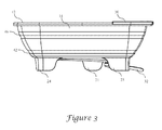
- FIG. 3 is a side elevational view of a preferred collapsible dish drainer.
- FIG. 4 is a top perspective exploded view of a preferred collapsible dish drainer.
- FIG. 5 is a bottom perspective exploded view of a preferred collapsible dish drainer.
- FIG. 6 is a top plan view of a preferred collapsible dish drainer, illustrated with an upper shelf in a retracted position.
- FIG. 7 is a top plan view of a preferred collapsible dish drainer, illustrated with an upper shelf in an expanded position.
- FIG. 8 is a bottom plan view of a preferred collapsible dish drainer.
- the dish drainer includes a lower base having an upper side 50 and a lower side 51 , an upper rim 12 , and side-walls 14 extending upwardly from the lower base to the upper rim.
- the base and the rim are formed from materials that are relatively more rigid than the material used for the sidewalk.
- the sidewalls are formed from a silicone material while the rim is formed from a plastic material.
- the entire dish strainer may be formed from a resilient material.
- the sidewalls of the dish drainer preferably include an upper living hinge 40 and a lower living hinge 42 , as best seen in FIG. 3 .
- the upper and lower living hinges are positioned relatively adjacent the rim and the base, respectively, to allow the dish drainer to be folded into three sections for relatively compact storage.
- the dish strainer may include additional living hinges if desired.
- the dish drainer includes a shelf 70 , which in the illustrated version is configured to slide laterally outward from the rim and inward to a position substantially within an area bounded by the rim.
- the shelf 70 In the top plan view of FIG. 6 , the shelf 70 is shown in a retracted position in which it is moved laterally inward in the direction of arrow B, overlying the base of the dish drainer.
- the shelf 70 In the top view of FIG. 7 , the shelf 70 is shown in an extended position, moved laterally outward in the direction of arrow C so that it extends laterally beyond and outside the boundary formed by the rim 12 of the dish drainer.
- the rim includes four holes 91 - 94 , best seen in FIG. 4 , which are configured to receive four retaining lugs 75 - 78 .
- the retaining lugs may be integrally formed with the rim or may be otherwise secured to the upper rim.
- the shelf 70 is formed with four slots 71 - 74 , with each of the four slots being positioned to slidably receive a separate one of the four lugs.
- two of the four slots are formed to be open-ended such that the slots extend all the way to and through the outer perimeter of the shelf.
- the other two slots are formed such that they are bounded around the entire perimeter by the shelf.
- the retaining lugs are each formed with an upper terminal end which is wider than a lower neck of the lug, with the corresponding slots formed in the shelf being sized such that the slots are smaller in width than the upper terminal end of the corresponding lug. Accordingly, the shelf may slide laterally back and forth along a path defined by the slots, while the shelf is retained against the upper rim 12 by the wider terminal end of the lugs.
- Each of the four slots is also formed to be parallel to one another, thereby defining a substantially linear path of travel of the shelf with respect to the dish drainer.
- the shelf 70 preferably further includes a peripheral downwardly depending flange, such as best seen in the bottom perspective view of FIG. 5 , to help prevent the shelf from traveling outwardly beyond the rim 12 of the dish drainer or inwardly beyond the edge of the rim.
- the flange includes an inner flange portion 80 formed along an interior edge of the shelf and an outer flange 82 formed along an exterior edge of the shelf.
- the downwardly depending flange may also extend along the sides and corners of the shelf, as shown.
- the flanges 80 , 82 combine to define limits to the path of lateral travel of the shelf 70 in both directions.
- the inner flange 80 abuts the rim 12 at the extended location while the outer flange 82 abuts the rim 12 at the retracted location of the shelf.
- the shelf is preferably formed with a plurality of openings 72 a - 72 f , as best seen in FIG. 4 , with the openings formed in the shelf being positioned to allow cutlery or other elongated items to be positioned within the openings for drying.
- six separate openings are provided, with two openings being positioned between the two central slots 72 , 73 , and two additional openings positioned on each of the two outer sides of the two central slots.
- the six openings are formed as three pairs of openings with a structural cross member separating each of the pairs.
- the upper side of the base 51 is preferably formed with a plurality of features to allow dishes be positioned on end for drying.
- the base includes a plurality of upwardly extending ribs 52 a , 52 b (see FIG. 1 ) evenly spaced apart from one another and configured to allow an edge of the plates to be received within the space between adjacent ribs.
- the ribs are formed as two rows of ribs positioned adjacent to and parallel to one another.
- a flatware retaining box 60 is also preferably formed on the upper side of the base 51 .
- the flatware retaining box is configured as an upwardly extending flange formed as an “F” shape in the floor of the dish drainer.
- the flatware retaining box is positioned in one corner of the base of the dish drainer, beneath four of the openings in the shelf, and is positioned such that the flanges close to but spaced apart from the upwardly extending outer edges of the dish drainer. This separation allows water to flow out of the flatware box rather than being trapped within it.
- the base of the dish drainer further includes a drain hole 36 (see FIG. 5 ), which in the illustrated version is positioned in a corner of the base adjacent the flatware box.
- the drain hole includes a drain grate 34 having a plurality of openings and being configured to block large solid items from passing through the drain hole.
- the drain grate 34 is formed as a short upright cylinder (best seen in FIG. 5 ) and the drain hole 36 is configured as a circular opening in the base of the dish drainer.
- the drain hole further includes a short downwardly extending annular flange about the perimeter of the drain hole, sized and shaped to receive the cylindrical drain grate.
- the drain grate further includes a laterally extending annular shelf 37 formed about a lower perimeter of the drain grate.
- the drain hole and drain grate may be formed as a single unitary component.
- the drain grate may be inserted into an upper side of the base rather than being inserted upwardly from the lower side of the base as illustrated.
- a drain spout 32 is pivotally attached to the drain hole, and in accordance with the illustrated preferred embodiment the drain spout attaches to the lateral shelf 37 of the drain grate 34 .
- the drain spout is formed with an elongated concave shape, allowing water to be directed within the shallow channel formed by the concave shape.
- the drain spout is open-topped.
- a short vertical sidewall 39 is formed at one end of the drain spout (that is, the end attached to the drain grate).
- the sidewall extends around a region at least somewhat greater than a semi-circle when viewed from the top, forming an approximate “C” shape.
- the vertical sidewall is sized and configured to receive the laterally extending annular shelf formed in the drain grate.
- An upper inward-directed abutment preferably formed as a plurality of stems 35 , trap the drain grate within the vertical sidewall for pivotal movement of the spout with respect to the drain grate.
- the spout is removable from the dish drainer to allow it to be cleaned and thoroughly dried between uses.
- the spout can be snap-fit onto the grate.
- the drain grate is removably attached to the base of the dish drainer.
- the base of the dish drainer is formed with one or more feet configured to allow the dish drainer to rest on a horizontal surface.
- the feet are preferably configured to create vertical space between the bottom edge of the feet and the lower surface of the base 50 , thereby allowing room for the spout to be positioned. In the same vertical space above a counter top and below the base of the dish drainer. In the illustrated version, several feet 21 - 24 are provided.
- one foot 21 is positioned along one side of the dish drainer and another foot 22 is positioned along a perpendicular side of the dish strainer.
- An opening 30 is thereby created at a bottom corner of the dish drainer, allowing pivotal movement of the spout as indicated by arrow A in FIG. 2 within the opening defined between feet 21 and 23 .
- the opening 30 is sized and spaced to allow pivotal movement of the spout along an arc of greater than 90° (see FIG. 8 ) to allow rotation of the spout and a wide range of optional positions of the dish drainer with respect to an adjacent sink.
- the opening 30 is defined by the space between edges of feet 21 and 23 closest to the spout 32 .
- a tangent line to a first foot 21 is defined by line D in FIG. 8
- a tangent line to a second foot 23 is defined by line E.
- the lines intersect to define an angle of about 90 degrees.
- the drain hole is positioned to allow the spout to be attached in the vicinity of the intersection of lines D and F, and most preferably at a location that enables pivotal movement of the spout within the 90 degrees defined by lines D and E. Accordingly, pivotal movement of the spout allows it to move between a first position adjacent the first foot 21 and a second position adjacent the second foot 23 , in which the first position is approximately 90 degrees rotated from the second position. As illustrated, the spout 32 occupies a third position, mid-way between the first and second positions.
Abstract
Description
Claims (15)
Priority Applications (1)
| Application Number | Priority Date | Filing Date | Title |
|---|---|---|---|
| US14/692,969 US9427136B2 (en) | 2014-04-22 | 2015-04-22 | Collapsible dish drainer |
Applications Claiming Priority (2)
| Application Number | Priority Date | Filing Date | Title |
|---|---|---|---|
| US201461982639P | 2014-04-22 | 2014-04-22 | |
| US14/692,969 US9427136B2 (en) | 2014-04-22 | 2015-04-22 | Collapsible dish drainer |
Publications (2)
| Publication Number | Publication Date |
|---|---|
| US20150297058A1 US20150297058A1 (en) | 2015-10-22 |
| US9427136B2 true US9427136B2 (en) | 2016-08-30 |
Family
ID=54320905
Family Applications (1)
| Application Number | Title | Priority Date | Filing Date |
|---|---|---|---|
| US14/692,969 Active US9427136B2 (en) | 2014-04-22 | 2015-04-22 | Collapsible dish drainer |
Country Status (1)
| Country | Link |
|---|---|
| US (1) | US9427136B2 (en) |
Cited By (2)
| Publication number | Priority date | Publication date | Assignee | Title |
|---|---|---|---|---|
| US11039731B2 (en) * | 2018-12-06 | 2021-06-22 | Hongyuan Han | Nesting, dish drying rack |
| USD966642S1 (en) * | 2020-12-01 | 2022-10-11 | Sam Tung Tsui | Drainer for drying wet hems |
Families Citing this family (1)
| Publication number | Priority date | Publication date | Assignee | Title |
|---|---|---|---|---|
| JP7157470B2 (en) * | 2020-08-27 | 2022-10-20 | シーピー化成株式会社 | tray container |
Citations (107)
| Publication number | Priority date | Publication date | Assignee | Title |
|---|---|---|---|---|
| US1270631A (en) * | 1916-11-23 | 1918-06-25 | Isabel L Lewis | Dish and silverware drainer. |
| US1487942A (en) * | 1922-04-04 | 1924-03-25 | Edwin G Hines | Dish drainer |
| US1643905A (en) * | 1927-03-30 | 1927-09-27 | May H Rossner | Combination dish drainer and tub cover |
| US1669284A (en) | 1925-08-31 | 1928-05-08 | Chetham Edward | Strainer |
| US1675855A (en) | 1927-10-12 | 1928-07-03 | Elsa S Kogler | Combination strainer and container |
| US1679594A (en) * | 1925-08-15 | 1928-08-07 | Washburn Co | Dish drier |
| US1789232A (en) * | 1930-01-30 | 1931-01-13 | Hertz Mary | Dish drainer |
| US1908128A (en) * | 1930-11-22 | 1933-05-09 | Bie Naomi I De | Dishwashing apparatus |
| US2006566A (en) | 1934-01-11 | 1935-07-02 | Katzinger Edward Co | Strainer |
| US2264238A (en) | 1940-05-23 | 1941-11-25 | Howard A Burdwood | Sieve |
| US2443404A (en) * | 1942-12-10 | 1948-06-15 | Tallarico Domiano | Drainboard for dishes |
| US2456912A (en) | 1945-03-22 | 1948-12-21 | Edwin N Burrows | Collapsible and adjustable filter and strainer |
| US2464921A (en) | 1944-05-29 | 1949-03-22 | Ekco Products Company | Strainer |
| US2520382A (en) | 1946-08-12 | 1950-08-29 | Edward V Conrad | Pot strainer |
| US2725087A (en) | 1954-02-23 | 1955-11-29 | Clifford S Potter | Collapsible container |
| US2732696A (en) | 1956-01-31 | baker | ||
| US2808938A (en) | 1953-07-30 | 1957-10-08 | Leonora W Glover | Household articles |
| US2936898A (en) * | 1957-12-03 | 1960-05-17 | Miguez Jose | Drying rack for dishes and tableware |
| US3027041A (en) * | 1960-05-13 | 1962-03-27 | Columbus Plastic Products Inc | Tableware drainer |
| US3220544A (en) | 1963-04-26 | 1965-11-30 | Walter C Lovell | Packaging and novel container employed therewith |
| US3300048A (en) | 1964-04-08 | 1967-01-24 | Pollock Samuel | Colander |
| US3442395A (en) * | 1967-09-05 | 1969-05-06 | Rubbermaid Inc | Plastic dish drainer |
| US3889837A (en) * | 1974-01-24 | 1975-06-17 | Pretty Products Inc | Dish drainer having integrally hinged sidewalls |
| US4001904A (en) | 1976-02-13 | 1977-01-11 | Gill Walter L | Kitchen utensil |
| USD244827S (en) | 1976-02-05 | 1977-06-28 | Belaco International Ltd. | Cleaning and draining device |
| US4147277A (en) | 1977-06-02 | 1979-04-03 | Dart Industries Inc. | Serving dish |
| GB2028675A (en) | 1978-08-25 | 1980-03-12 | Winberg R | Improved beverage filter |
| US4220534A (en) | 1978-10-04 | 1980-09-02 | Perry Joseph F | Food straining |
| USD259535S (en) | 1979-05-03 | 1981-06-16 | Dart Industries Inc. | Colander or the like |
| US4372448A (en) * | 1980-12-01 | 1983-02-08 | Edward Drach | Multi-purpose kitchen device |
| US4377191A (en) * | 1976-07-03 | 1983-03-22 | Kabushiki Kaisha Ekijibishon | Collapsible container |
| US4419103A (en) | 1978-09-07 | 1983-12-06 | Balkan Thelma E | Method and apparatus for coloring Easter eggs |
| USD272972S (en) | 1981-08-03 | 1984-03-13 | Dart Industries Inc. | Sifter or the like |
| US4480343A (en) * | 1983-04-04 | 1984-11-06 | Edward Drach | Combination drain and cutting board |
| USD286490S (en) | 1982-10-20 | 1986-11-04 | Carlson Arthur R | Colander |
| US4622146A (en) | 1983-07-25 | 1986-11-11 | Brien Robert O | Flexible paint strainer |
| US4873100A (en) | 1987-04-15 | 1989-10-10 | The Procter & Gamble Company | Bistable expandable bottle |
| US5035800A (en) | 1989-06-28 | 1991-07-30 | E-Z Strainer, Inc. | Flexible strainer with a releasable cord |
| US5226551A (en) | 1991-11-12 | 1993-07-13 | Robbins Edward S Iii | Reusable and re-collapsible container |
| USD346725S (en) | 1993-07-15 | 1994-05-10 | American Standard Inc. | Colander |
| US5384173A (en) | 1992-05-08 | 1995-01-24 | Fuji Photo Film Co., Ltd. | Container for photographic film, its production and photographic film package |
| US5392941A (en) | 1991-11-12 | 1995-02-28 | Robbins, Iii; Edward S. | Reusable and re-collapsible container and associated cap |
| USD359202S (en) | 1994-02-02 | 1995-06-13 | Dart Industries Inc. | Colander lid |
| US5439128A (en) | 1992-05-12 | 1995-08-08 | Fishman; Avraham | Container |
| EP0719708A1 (en) | 1994-12-30 | 1996-07-03 | The Procter & Gamble Company | Collapsible scoop |
| US5549213A (en) | 1991-11-12 | 1996-08-27 | Edward S. Robbins, III | Reusable re-collapsible container and resealable cap |
| US5584413A (en) | 1994-06-09 | 1996-12-17 | Jung; Myung G. | Pleated plastic container |
| US5632406A (en) | 1995-10-11 | 1997-05-27 | Robbins, Iii; Edward S. | Side wall construction for collapsible containers |
| JPH09192031A (en) | 1996-01-23 | 1997-07-29 | Yasuo Fuse | Rotary water exhausting basket and saucer for fixing the same |
| CA2245807A1 (en) | 1996-02-12 | 1997-08-14 | Michael Gerard Willemsen | Collapsible container for fluids |
| US5860556A (en) | 1996-04-10 | 1999-01-19 | Robbins, Iii; Edward S. | Collapsible storage container |
| US5900293A (en) | 1996-12-26 | 1999-05-04 | S. C. Johnson Home Storage Inc. | Collapsible, monolayer microwaveable container |
| US5911338A (en) | 1998-04-16 | 1999-06-15 | Miller; Lee D. | Adjustable container |
| US5913448A (en) | 1997-07-08 | 1999-06-22 | Rubbermaid Incorporated | Collapsible container |
| US6035766A (en) | 1999-07-09 | 2000-03-14 | Schirmer; Patricia C. | Multi-heating zone cooking pot construction |
| US6103116A (en) | 1998-10-01 | 2000-08-15 | Kx Industries, L.P. | Collapsible filter |
| USD433884S (en) | 2000-01-27 | 2000-11-21 | Dart Industries Inc. | Colander with scrubbing interior |
| US6158620A (en) | 1999-02-11 | 2000-12-12 | Chester Labs, Inc. | Collapsible container |
| US6202542B1 (en) | 1996-12-16 | 2001-03-20 | Espire Incorporated | Lid for beverage container |
| US6315151B1 (en) | 2000-01-11 | 2001-11-13 | The Procter & Gamble Co. | Collapsible container and method of making |
| US6364152B1 (en) | 2000-04-12 | 2002-04-02 | Dart Industries Inc. | Food storage container |
| US6367409B1 (en) | 1998-08-04 | 2002-04-09 | Gdsk International, Inc. | Food coating apparatus |
| USD469667S1 (en) | 2002-01-07 | 2003-02-04 | Wki Holding Company, Inc. | Colander |
| US6547080B1 (en) | 2000-03-16 | 2003-04-15 | Gravity, Incorporated | Collapsible colander for straining and rinsing |
| US20030217649A1 (en) | 2002-03-29 | 2003-11-27 | Luca Leonori | Colander with reduced dimensions |
| US6736285B2 (en) | 2002-02-01 | 2004-05-18 | Theo A. Stewart-Stand | Collapsible drinking and storage receptacle |
| US6758348B2 (en) | 2001-04-05 | 2004-07-06 | Kathleen J. Adkins | Space saving dish strainer |
| US6811051B2 (en) | 2002-01-31 | 2004-11-02 | Gohsho Company, Ltd. | Metal container capable of retaining a state of being reduced in a longitudinal direction and reduction method thereof |
| USD502847S1 (en) | 2003-03-21 | 2005-03-15 | Dms Distribution + Marketing Service Ag | Collapsible colander with reduced dimensions |
| USD503313S1 (en) | 2004-02-27 | 2005-03-29 | Ellis N. Shamoon | Strainer |
| US20050127073A1 (en) | 2003-12-16 | 2005-06-16 | David Kusuma | Collapsible container |
| US6949190B2 (en) | 2002-12-13 | 2005-09-27 | Hutzler Manufacturing Co., Inc. | Device combining 3 functions in one for washing, serving and storing berries, grapes, and other fruits |
| USD514764S1 (en) | 2002-11-22 | 2006-02-07 | Kanei Kogyo Kabushiki Kaisha | Drain basket retainable on sink |
| US20060096929A1 (en) * | 2004-10-21 | 2006-05-11 | Timothy Repp | Collapsible strainer |
| WO2006054168A1 (en) | 2004-11-19 | 2006-05-26 | Pavoni Italia S.P.A. | Flexible colander |
| USD522809S1 (en) | 2004-07-22 | 2006-06-13 | Dart Industries Inc. | Container |
| USD534701S1 (en) * | 2005-10-25 | 2007-01-02 | Creative Bath Products, Inc. | Expandable dish rack |
| EP1764017A1 (en) | 2005-12-08 | 2007-03-21 | Clever Edge, Inc. | Strainer |
| US20070090063A1 (en) * | 2005-10-25 | 2007-04-26 | Creative Bath Products, Inc. | Expandable dish rack assembly |
| USD545137S1 (en) | 2005-09-23 | 2007-06-26 | Rubbermaid Incorporated | Collapsible storage container |
| US20070181489A1 (en) | 2006-02-08 | 2007-08-09 | Lee Elizabeth K Y | Straining device |
| US20070251874A1 (en) * | 2006-04-28 | 2007-11-01 | Chef'n Corporation | Collapsible straining device |
| USD555311S1 (en) * | 2006-12-12 | 2007-11-13 | Simplehuman Llc | Dish rack |
| USD555310S1 (en) * | 2006-11-15 | 2007-11-13 | Simplehuman Llc | Dish rack |
| US7325694B2 (en) | 2003-09-22 | 2008-02-05 | Bushey Richard D | Flexible strainer |
| US7325695B2 (en) * | 2005-06-20 | 2008-02-05 | Simplehuman Llc | Dish rack with water drainage mechanism |
| EP1917890A1 (en) | 2006-10-31 | 2008-05-07 | Duncan C. Fung | Foldable ovenware container and method of production |
| CA2602047A1 (en) | 2007-03-22 | 2008-09-22 | Progressive International Corporation | Collapsible colander and bowl |
| CA2602253A1 (en) | 2007-06-28 | 2008-12-28 | Kwok Kuen So | Bowl and basket assembly and salad spinner incorporating such an assembly |
| USD586061S1 (en) * | 2008-06-05 | 2009-02-03 | Progressive International Corporation | Collapsible over the sink dish drainer |
| WO2009023892A1 (en) | 2007-08-17 | 2009-02-26 | Sea To Summit Pty Ltd | Collapsible container |
| USD599069S1 (en) * | 2009-02-10 | 2009-08-25 | Progressive International Coporation | Collapsible dish drainer |
| US20090211994A1 (en) * | 2008-01-29 | 2009-08-27 | Simplehuman Llc | Dish rack |
| US20100059460A1 (en) * | 2008-09-10 | 2010-03-11 | Azanaw Mulaw | Dish rack with removable grate |
| US7748543B2 (en) * | 2004-12-29 | 2010-07-06 | Simplehuman Llc | Tilting dish rack assembly |
| USD624721S1 (en) * | 2009-12-07 | 2010-09-28 | Progressive International Corporation | Collapsible dish tub |
| US7857147B2 (en) * | 2008-09-10 | 2010-12-28 | Azanaw Mulaw | Dish rack with splash guard and dish towel drying handles |
| USD646450S1 (en) * | 2010-03-12 | 2011-10-04 | Simplehuman Llc | Dishrack |
| US8074813B2 (en) * | 2006-11-17 | 2011-12-13 | Simplehuman Llc | Dish rack with adjustable spout and removable drip tray |
| USD651779S1 (en) * | 2011-07-28 | 2012-01-03 | Balkum Frank R | Dishwashing pan |
| USD669318S1 (en) | 2012-01-26 | 2012-10-23 | Progressive International Corporation | Collapsible container |
| USD692200S1 (en) * | 2013-03-01 | 2013-10-22 | Robinson Home Products Inc. | Dish rack |
| US20140061193A1 (en) * | 2012-08-31 | 2014-03-06 | Daniel A. Sudakoff | Collapsible food container |
| US20140246445A1 (en) * | 2013-03-01 | 2014-09-04 | Robinson Home Products Inc. | Angled collapsible container |
| USD714508S1 (en) * | 2014-03-14 | 2014-09-30 | Devee Joy | Collapsible dish rack |
| US8925743B1 (en) * | 2013-08-30 | 2015-01-06 | Helen Of Troy Limited | Dish drying rack |
| US20150251808A1 (en) * | 2014-03-10 | 2015-09-10 | Sam Tung Tsui | Collapsible Household Containers |
-
2015
- 2015-04-22 US US14/692,969 patent/US9427136B2/en active Active
Patent Citations (114)
| Publication number | Priority date | Publication date | Assignee | Title |
|---|---|---|---|---|
| US2732696A (en) | 1956-01-31 | baker | ||
| US1270631A (en) * | 1916-11-23 | 1918-06-25 | Isabel L Lewis | Dish and silverware drainer. |
| US1487942A (en) * | 1922-04-04 | 1924-03-25 | Edwin G Hines | Dish drainer |
| US1679594A (en) * | 1925-08-15 | 1928-08-07 | Washburn Co | Dish drier |
| US1669284A (en) | 1925-08-31 | 1928-05-08 | Chetham Edward | Strainer |
| US1643905A (en) * | 1927-03-30 | 1927-09-27 | May H Rossner | Combination dish drainer and tub cover |
| US1675855A (en) | 1927-10-12 | 1928-07-03 | Elsa S Kogler | Combination strainer and container |
| US1789232A (en) * | 1930-01-30 | 1931-01-13 | Hertz Mary | Dish drainer |
| US1908128A (en) * | 1930-11-22 | 1933-05-09 | Bie Naomi I De | Dishwashing apparatus |
| US2006566A (en) | 1934-01-11 | 1935-07-02 | Katzinger Edward Co | Strainer |
| US2264238A (en) | 1940-05-23 | 1941-11-25 | Howard A Burdwood | Sieve |
| US2443404A (en) * | 1942-12-10 | 1948-06-15 | Tallarico Domiano | Drainboard for dishes |
| US2464921A (en) | 1944-05-29 | 1949-03-22 | Ekco Products Company | Strainer |
| US2456912A (en) | 1945-03-22 | 1948-12-21 | Edwin N Burrows | Collapsible and adjustable filter and strainer |
| US2520382A (en) | 1946-08-12 | 1950-08-29 | Edward V Conrad | Pot strainer |
| US2808938A (en) | 1953-07-30 | 1957-10-08 | Leonora W Glover | Household articles |
| US2725087A (en) | 1954-02-23 | 1955-11-29 | Clifford S Potter | Collapsible container |
| US2936898A (en) * | 1957-12-03 | 1960-05-17 | Miguez Jose | Drying rack for dishes and tableware |
| US3027041A (en) * | 1960-05-13 | 1962-03-27 | Columbus Plastic Products Inc | Tableware drainer |
| US3220544A (en) | 1963-04-26 | 1965-11-30 | Walter C Lovell | Packaging and novel container employed therewith |
| US3300048A (en) | 1964-04-08 | 1967-01-24 | Pollock Samuel | Colander |
| US3442395A (en) * | 1967-09-05 | 1969-05-06 | Rubbermaid Inc | Plastic dish drainer |
| US3889837A (en) * | 1974-01-24 | 1975-06-17 | Pretty Products Inc | Dish drainer having integrally hinged sidewalls |
| USD244827S (en) | 1976-02-05 | 1977-06-28 | Belaco International Ltd. | Cleaning and draining device |
| US4001904A (en) | 1976-02-13 | 1977-01-11 | Gill Walter L | Kitchen utensil |
| US4377191A (en) * | 1976-07-03 | 1983-03-22 | Kabushiki Kaisha Ekijibishon | Collapsible container |
| US4147277A (en) | 1977-06-02 | 1979-04-03 | Dart Industries Inc. | Serving dish |
| GB2028675A (en) | 1978-08-25 | 1980-03-12 | Winberg R | Improved beverage filter |
| US4419103A (en) | 1978-09-07 | 1983-12-06 | Balkan Thelma E | Method and apparatus for coloring Easter eggs |
| US4220534A (en) | 1978-10-04 | 1980-09-02 | Perry Joseph F | Food straining |
| USD259535S (en) | 1979-05-03 | 1981-06-16 | Dart Industries Inc. | Colander or the like |
| US4372448A (en) * | 1980-12-01 | 1983-02-08 | Edward Drach | Multi-purpose kitchen device |
| USD272972S (en) | 1981-08-03 | 1984-03-13 | Dart Industries Inc. | Sifter or the like |
| USD286490S (en) | 1982-10-20 | 1986-11-04 | Carlson Arthur R | Colander |
| US4480343A (en) * | 1983-04-04 | 1984-11-06 | Edward Drach | Combination drain and cutting board |
| US4622146A (en) | 1983-07-25 | 1986-11-11 | Brien Robert O | Flexible paint strainer |
| US4873100A (en) | 1987-04-15 | 1989-10-10 | The Procter & Gamble Company | Bistable expandable bottle |
| US5035800A (en) | 1989-06-28 | 1991-07-30 | E-Z Strainer, Inc. | Flexible strainer with a releasable cord |
| US5226551A (en) | 1991-11-12 | 1993-07-13 | Robbins Edward S Iii | Reusable and re-collapsible container |
| US5392941A (en) | 1991-11-12 | 1995-02-28 | Robbins, Iii; Edward S. | Reusable and re-collapsible container and associated cap |
| US5417337A (en) | 1991-11-12 | 1995-05-23 | Robbins, Iii; Edward S. | Reusable and re-collapsible container and associated cap |
| US5549213A (en) | 1991-11-12 | 1996-08-27 | Edward S. Robbins, III | Reusable re-collapsible container and resealable cap |
| US5575398A (en) | 1991-11-12 | 1996-11-19 | Robbins, Iii; Edward S. | Reusable and re-collapsible container and associated cap |
| US5533638A (en) | 1991-11-12 | 1996-07-09 | Robbins, Iii; Edward S. | Reusable and re-collapsible container and associated cap |
| US5384173A (en) | 1992-05-08 | 1995-01-24 | Fuji Photo Film Co., Ltd. | Container for photographic film, its production and photographic film package |
| US5439128A (en) | 1992-05-12 | 1995-08-08 | Fishman; Avraham | Container |
| USD346725S (en) | 1993-07-15 | 1994-05-10 | American Standard Inc. | Colander |
| USD359202S (en) | 1994-02-02 | 1995-06-13 | Dart Industries Inc. | Colander lid |
| US5584413A (en) | 1994-06-09 | 1996-12-17 | Jung; Myung G. | Pleated plastic container |
| EP0719708A1 (en) | 1994-12-30 | 1996-07-03 | The Procter & Gamble Company | Collapsible scoop |
| US5632406A (en) | 1995-10-11 | 1997-05-27 | Robbins, Iii; Edward S. | Side wall construction for collapsible containers |
| JPH09192031A (en) | 1996-01-23 | 1997-07-29 | Yasuo Fuse | Rotary water exhausting basket and saucer for fixing the same |
| CA2245807A1 (en) | 1996-02-12 | 1997-08-14 | Michael Gerard Willemsen | Collapsible container for fluids |
| US5860556A (en) | 1996-04-10 | 1999-01-19 | Robbins, Iii; Edward S. | Collapsible storage container |
| US6202542B1 (en) | 1996-12-16 | 2001-03-20 | Espire Incorporated | Lid for beverage container |
| US5900293A (en) | 1996-12-26 | 1999-05-04 | S. C. Johnson Home Storage Inc. | Collapsible, monolayer microwaveable container |
| US5913448A (en) | 1997-07-08 | 1999-06-22 | Rubbermaid Incorporated | Collapsible container |
| US5911338A (en) | 1998-04-16 | 1999-06-15 | Miller; Lee D. | Adjustable container |
| US6367409B1 (en) | 1998-08-04 | 2002-04-09 | Gdsk International, Inc. | Food coating apparatus |
| US6103116A (en) | 1998-10-01 | 2000-08-15 | Kx Industries, L.P. | Collapsible filter |
| US6158620A (en) | 1999-02-11 | 2000-12-12 | Chester Labs, Inc. | Collapsible container |
| US6035766A (en) | 1999-07-09 | 2000-03-14 | Schirmer; Patricia C. | Multi-heating zone cooking pot construction |
| US6315151B1 (en) | 2000-01-11 | 2001-11-13 | The Procter & Gamble Co. | Collapsible container and method of making |
| USD433884S (en) | 2000-01-27 | 2000-11-21 | Dart Industries Inc. | Colander with scrubbing interior |
| US6547080B1 (en) | 2000-03-16 | 2003-04-15 | Gravity, Incorporated | Collapsible colander for straining and rinsing |
| US6364152B1 (en) | 2000-04-12 | 2002-04-02 | Dart Industries Inc. | Food storage container |
| US6758348B2 (en) | 2001-04-05 | 2004-07-06 | Kathleen J. Adkins | Space saving dish strainer |
| USD469667S1 (en) | 2002-01-07 | 2003-02-04 | Wki Holding Company, Inc. | Colander |
| US6811051B2 (en) | 2002-01-31 | 2004-11-02 | Gohsho Company, Ltd. | Metal container capable of retaining a state of being reduced in a longitudinal direction and reduction method thereof |
| US6736285B2 (en) | 2002-02-01 | 2004-05-18 | Theo A. Stewart-Stand | Collapsible drinking and storage receptacle |
| US20030217649A1 (en) | 2002-03-29 | 2003-11-27 | Luca Leonori | Colander with reduced dimensions |
| USD514764S1 (en) | 2002-11-22 | 2006-02-07 | Kanei Kogyo Kabushiki Kaisha | Drain basket retainable on sink |
| US6949190B2 (en) | 2002-12-13 | 2005-09-27 | Hutzler Manufacturing Co., Inc. | Device combining 3 functions in one for washing, serving and storing berries, grapes, and other fruits |
| USD502847S1 (en) | 2003-03-21 | 2005-03-15 | Dms Distribution + Marketing Service Ag | Collapsible colander with reduced dimensions |
| US7325694B2 (en) | 2003-09-22 | 2008-02-05 | Bushey Richard D | Flexible strainer |
| US20050127074A1 (en) * | 2003-12-16 | 2005-06-16 | David Kusuma | Collapsible container |
| US20050127073A1 (en) | 2003-12-16 | 2005-06-16 | David Kusuma | Collapsible container |
| USD503313S1 (en) | 2004-02-27 | 2005-03-29 | Ellis N. Shamoon | Strainer |
| USD522809S1 (en) | 2004-07-22 | 2006-06-13 | Dart Industries Inc. | Container |
| US20060096929A1 (en) * | 2004-10-21 | 2006-05-11 | Timothy Repp | Collapsible strainer |
| WO2006054168A1 (en) | 2004-11-19 | 2006-05-26 | Pavoni Italia S.P.A. | Flexible colander |
| US7748543B2 (en) * | 2004-12-29 | 2010-07-06 | Simplehuman Llc | Tilting dish rack assembly |
| US7325695B2 (en) * | 2005-06-20 | 2008-02-05 | Simplehuman Llc | Dish rack with water drainage mechanism |
| USD545137S1 (en) | 2005-09-23 | 2007-06-26 | Rubbermaid Incorporated | Collapsible storage container |
| US20070090063A1 (en) * | 2005-10-25 | 2007-04-26 | Creative Bath Products, Inc. | Expandable dish rack assembly |
| USD534701S1 (en) * | 2005-10-25 | 2007-01-02 | Creative Bath Products, Inc. | Expandable dish rack |
| EP1764017A1 (en) | 2005-12-08 | 2007-03-21 | Clever Edge, Inc. | Strainer |
| US20070181489A1 (en) | 2006-02-08 | 2007-08-09 | Lee Elizabeth K Y | Straining device |
| US20070251874A1 (en) * | 2006-04-28 | 2007-11-01 | Chef'n Corporation | Collapsible straining device |
| AU2007200570A1 (en) | 2006-10-31 | 2008-05-15 | Duncan C. Fung | Foldable ovenware container and method of production |
| EP1917890A1 (en) | 2006-10-31 | 2008-05-07 | Duncan C. Fung | Foldable ovenware container and method of production |
| USD555310S1 (en) * | 2006-11-15 | 2007-11-13 | Simplehuman Llc | Dish rack |
| US8074813B2 (en) * | 2006-11-17 | 2011-12-13 | Simplehuman Llc | Dish rack with adjustable spout and removable drip tray |
| USD555311S1 (en) * | 2006-12-12 | 2007-11-13 | Simplehuman Llc | Dish rack |
| CA2602047A1 (en) | 2007-03-22 | 2008-09-22 | Progressive International Corporation | Collapsible colander and bowl |
| US8871092B2 (en) * | 2007-03-22 | 2014-10-28 | Progressive International Corporation | Collapsible colander and bowl |
| US7678271B2 (en) * | 2007-03-22 | 2010-03-16 | Progressive International Corporation | Collapsible colander and bowl |
| CA2602253A1 (en) | 2007-06-28 | 2008-12-28 | Kwok Kuen So | Bowl and basket assembly and salad spinner incorporating such an assembly |
| WO2009023892A1 (en) | 2007-08-17 | 2009-02-26 | Sea To Summit Pty Ltd | Collapsible container |
| US20090211994A1 (en) * | 2008-01-29 | 2009-08-27 | Simplehuman Llc | Dish rack |
| USD586061S1 (en) * | 2008-06-05 | 2009-02-03 | Progressive International Corporation | Collapsible over the sink dish drainer |
| US7857147B2 (en) * | 2008-09-10 | 2010-12-28 | Azanaw Mulaw | Dish rack with splash guard and dish towel drying handles |
| US20100059460A1 (en) * | 2008-09-10 | 2010-03-11 | Azanaw Mulaw | Dish rack with removable grate |
| USD599069S1 (en) * | 2009-02-10 | 2009-08-25 | Progressive International Coporation | Collapsible dish drainer |
| USD624721S1 (en) * | 2009-12-07 | 2010-09-28 | Progressive International Corporation | Collapsible dish tub |
| USD646450S1 (en) * | 2010-03-12 | 2011-10-04 | Simplehuman Llc | Dishrack |
| USD651779S1 (en) * | 2011-07-28 | 2012-01-03 | Balkum Frank R | Dishwashing pan |
| USD669318S1 (en) | 2012-01-26 | 2012-10-23 | Progressive International Corporation | Collapsible container |
| US20140061193A1 (en) * | 2012-08-31 | 2014-03-06 | Daniel A. Sudakoff | Collapsible food container |
| USD692200S1 (en) * | 2013-03-01 | 2013-10-22 | Robinson Home Products Inc. | Dish rack |
| US20140246445A1 (en) * | 2013-03-01 | 2014-09-04 | Robinson Home Products Inc. | Angled collapsible container |
| US8925743B1 (en) * | 2013-08-30 | 2015-01-06 | Helen Of Troy Limited | Dish drying rack |
| US20150251808A1 (en) * | 2014-03-10 | 2015-09-10 | Sam Tung Tsui | Collapsible Household Containers |
| USD714508S1 (en) * | 2014-03-14 | 2014-09-30 | Devee Joy | Collapsible dish rack |
Non-Patent Citations (5)
| Title |
|---|
| "One Source for Silicone Innovation", Dexas International, Ltd.; www.dexas.com; 1 page; 2006. |
| "Prepology Set of 3 Silicone Collapsible Colanders," QVC, http://www.qvc.com/scripts/detail.dll, 5 pages, Printed Jul. 5, 2006. |
| "Strainer". Good Design 2005, Norman Copenhagen, http://www.norman-copenhagen.com/the1.html, 1 page, Printed Jul. 13, 2006. |
| "The Norman Collapsible Colander," Smart Stuff, www.smartstuff.se; 2 pages, Aug. 2005. |
| "The Norman Collapsible Colander," Smart Stuff, www.smartsuff.se; 2 pages, Aug. 2005. |
Cited By (2)
| Publication number | Priority date | Publication date | Assignee | Title |
|---|---|---|---|---|
| US11039731B2 (en) * | 2018-12-06 | 2021-06-22 | Hongyuan Han | Nesting, dish drying rack |
| USD966642S1 (en) * | 2020-12-01 | 2022-10-11 | Sam Tung Tsui | Drainer for drying wet hems |
Also Published As
| Publication number | Publication date |
|---|---|
| US20150297058A1 (en) | 2015-10-22 |
Similar Documents
| Publication | Publication Date | Title |
|---|---|---|
| CA2610322C (en) | Dish rack having adjustable spout and removable drip tray | |
| US9386886B2 (en) | Over sink kitchen work station | |
| US7325695B2 (en) | Dish rack with water drainage mechanism | |
| US10988896B2 (en) | Collapsible household containers | |
| US9907453B2 (en) | Combination dish drying mat and rack | |
| US20080283480A1 (en) | Collapsible Dish Rack | |
| US7407059B2 (en) | Drying storage rack | |
| US8087108B2 (en) | Sink protector | |
| CN104229257B (en) | Collapsible household container | |
| US20140246445A1 (en) | Angled collapsible container | |
| US8960452B2 (en) | Drying rack assembly | |
| US9730571B1 (en) | Foldable dish rack | |
| EP1679028A2 (en) | Dish rack assembly with water drain device | |
| US9427136B2 (en) | Collapsible dish drainer | |
| US10271710B2 (en) | Drying rack | |
| JP7126462B2 (en) | reconfigurable container | |
| US20040238464A1 (en) | Dish rack draining tray providing stability and effective draining | |
| US7207074B1 (en) | Dish drying rack system | |
| US20100065517A1 (en) | Dish drainer | |
| US2954875A (en) | Combination dish rack and drainboard | |
| KR200471944Y1 (en) | Tableware Dryer | |
| KR20100000767U (en) | a bamboo basket for sink | |
| US20180153350A1 (en) | Portable Campground Sink | |
| KR200265916Y1 (en) | Drying deck of kitchen sink | |
| KR101556720B1 (en) | Dish drainer for a sink |
Legal Events
| Date | Code | Title | Description |
|---|---|---|---|
| AS | Assignment |
Owner name: PROGRESSIVE INTERNATIONAL CORPORATION, WASHINGTON Free format text: ASSIGNMENT OF ASSIGNORS INTEREST;ASSIGNOR:KENT, JOSEPH;REEL/FRAME:035468/0065 Effective date: 20150421 |
|
| STCF | Information on status: patent grant |
Free format text: PATENTED CASE |
|
| AS | Assignment |
Owner name: WELLS FARGO BANK, NATIONAL ASSOCIATION, OREGON Free format text: SECURITY INTEREST;ASSIGNOR:PROGRESSIVE INTERNATIONAL CORPORATION;REEL/FRAME:043479/0304 Effective date: 20170731 |
|
| MAFP | Maintenance fee payment |
Free format text: PAYMENT OF MAINTENANCE FEE, 4TH YR, SMALL ENTITY (ORIGINAL EVENT CODE: M2551); ENTITY STATUS OF PATENT OWNER: SMALL ENTITY Year of fee payment: 4 |
|
| AS | Assignment |
Owner name: PROGRESSIVE INTERNATIONAL CORPORATION, WASHINGTON Free format text: RELEASE BY SECURED PARTY;ASSIGNOR:WELLS FARGO BANK, NATIONAL ASSOCIATION;REEL/FRAME:066366/0813 Effective date: 20240123 |
|
| MAFP | Maintenance fee payment |
Free format text: PAYMENT OF MAINTENANCE FEE, 8TH YR, SMALL ENTITY (ORIGINAL EVENT CODE: M2552); ENTITY STATUS OF PATENT OWNER: SMALL ENTITY Year of fee payment: 8 |
|
| AS | Assignment |
Owner name: ALTER DOMUS (US) LLC, AS ADMINISTRATIVE AGENT, ILLINOIS Free format text: SECURITY INTEREST;ASSIGNORS:BASE4 VENTURES, LLC;EXCITE USA, LLC;PROGRESSIVE INTERNATIONAL CORPORATION;REEL/FRAME:066836/0803 Effective date: 20240229 |