US9417176B2 - Method and apparatus for detecting and registering properties of samples - Google Patents
Method and apparatus for detecting and registering properties of samples Download PDFInfo
- Publication number
- US9417176B2 US9417176B2 US12/522,877 US52287707A US9417176B2 US 9417176 B2 US9417176 B2 US 9417176B2 US 52287707 A US52287707 A US 52287707A US 9417176 B2 US9417176 B2 US 9417176B2
- Authority
- US
- United States
- Prior art keywords
- solution
- laser
- laser beam
- contaminant particles
- container
- Prior art date
- Legal status (The legal status is an assumption and is not a legal conclusion. Google has not performed a legal analysis and makes no representation as to the accuracy of the status listed.)
- Active, expires
Links
- 238000000034 method Methods 0.000 title claims abstract description 17
- 239000002245 particle Substances 0.000 claims description 21
- 230000005284 excitation Effects 0.000 claims description 11
- 230000003287 optical effect Effects 0.000 claims description 8
- 238000001917 fluorescence detection Methods 0.000 claims description 3
- 239000000356 contaminant Substances 0.000 claims 8
- 239000006193 liquid solution Substances 0.000 claims 3
- 239000000523 sample Substances 0.000 description 19
- 238000004458 analytical method Methods 0.000 description 10
- 238000001514 detection method Methods 0.000 description 6
- 239000000835 fiber Substances 0.000 description 3
- 238000004811 liquid chromatography Methods 0.000 description 3
- 238000012800 visualization Methods 0.000 description 3
- 239000000538 analytical sample Substances 0.000 description 2
- 238000000149 argon plasma sintering Methods 0.000 description 2
- 238000005515 capillary zone electrophoresis Methods 0.000 description 2
- 238000002296 dynamic light scattering Methods 0.000 description 2
- 238000011156 evaluation Methods 0.000 description 2
- 238000001506 fluorescence spectroscopy Methods 0.000 description 2
- 238000004128 high performance liquid chromatography Methods 0.000 description 2
- 239000012633 leachable Substances 0.000 description 2
- 238000005259 measurement Methods 0.000 description 2
- 239000000825 pharmaceutical preparation Substances 0.000 description 2
- 102000004169 proteins and genes Human genes 0.000 description 2
- 108090000623 proteins and genes Proteins 0.000 description 2
- 238000001370 static light scattering Methods 0.000 description 2
- 238000004566 IR spectroscopy Methods 0.000 description 1
- 238000001069 Raman spectroscopy Methods 0.000 description 1
- 238000010521 absorption reaction Methods 0.000 description 1
- 230000006978 adaptation Effects 0.000 description 1
- 238000007818 agglutination assay Methods 0.000 description 1
- 238000004166 bioassay Methods 0.000 description 1
- 239000008280 blood Substances 0.000 description 1
- 210000004369 blood Anatomy 0.000 description 1
- 238000012512 characterization method Methods 0.000 description 1
- 238000004587 chromatography analysis Methods 0.000 description 1
- 238000002983 circular dichroism Methods 0.000 description 1
- 238000009826 distribution Methods 0.000 description 1
- 230000000694 effects Effects 0.000 description 1
- 230000007717 exclusion Effects 0.000 description 1
- 238000001825 field-flow fractionation Methods 0.000 description 1
- 238000005194 fractionation Methods 0.000 description 1
- 238000011835 investigation Methods 0.000 description 1
- 238000004255 ion exchange chromatography Methods 0.000 description 1
- 238000001155 isoelectric focusing Methods 0.000 description 1
- 238000004519 manufacturing process Methods 0.000 description 1
- 239000013618 particulate matter Substances 0.000 description 1
- 229940127557 pharmaceutical product Drugs 0.000 description 1
- 238000003672 processing method Methods 0.000 description 1
- 239000012488 sample solution Substances 0.000 description 1
- 238000004611 spectroscopical analysis Methods 0.000 description 1
- 239000000126 substance Substances 0.000 description 1
- 230000000007 visual effect Effects 0.000 description 1
Images


Classifications
-
- G—PHYSICS
- G01—MEASURING; TESTING
- G01N—INVESTIGATING OR ANALYSING MATERIALS BY DETERMINING THEIR CHEMICAL OR PHYSICAL PROPERTIES
- G01N15/00—Investigating characteristics of particles; Investigating permeability, pore-volume, or surface-area of porous materials
- G01N15/02—Investigating particle size or size distribution
- G01N15/0205—Investigating particle size or size distribution by optical means, e.g. by light scattering, diffraction, holography or imaging
- G01N15/0227—Investigating particle size or size distribution by optical means, e.g. by light scattering, diffraction, holography or imaging using imaging, e.g. a projected image of suspension; using holography
-
- G—PHYSICS
- G01—MEASURING; TESTING
- G01N—INVESTIGATING OR ANALYSING MATERIALS BY DETERMINING THEIR CHEMICAL OR PHYSICAL PROPERTIES
- G01N21/00—Investigating or analysing materials by the use of optical means, i.e. using sub-millimetre waves, infrared, visible or ultraviolet light
- G01N21/17—Systems in which incident light is modified in accordance with the properties of the material investigated
- G01N21/47—Scattering, i.e. diffuse reflection
- G01N21/49—Scattering, i.e. diffuse reflection within a body or fluid
- G01N21/51—Scattering, i.e. diffuse reflection within a body or fluid inside a container, e.g. in an ampoule
-
- G—PHYSICS
- G01—MEASURING; TESTING
- G01N—INVESTIGATING OR ANALYSING MATERIALS BY DETERMINING THEIR CHEMICAL OR PHYSICAL PROPERTIES
- G01N21/00—Investigating or analysing materials by the use of optical means, i.e. using sub-millimetre waves, infrared, visible or ultraviolet light
- G01N21/62—Systems in which the material investigated is excited whereby it emits light or causes a change in wavelength of the incident light
- G01N21/63—Systems in which the material investigated is excited whereby it emits light or causes a change in wavelength of the incident light optically excited
- G01N21/64—Fluorescence; Phosphorescence
- G01N21/6402—Atomic fluorescence; Laser induced fluorescence
-
- G—PHYSICS
- G01—MEASURING; TESTING
- G01N—INVESTIGATING OR ANALYSING MATERIALS BY DETERMINING THEIR CHEMICAL OR PHYSICAL PROPERTIES
- G01N15/00—Investigating characteristics of particles; Investigating permeability, pore-volume, or surface-area of porous materials
- G01N15/02—Investigating particle size or size distribution
- G01N2015/0294—Particle shape
-
- G—PHYSICS
- G01—MEASURING; TESTING
- G01N—INVESTIGATING OR ANALYSING MATERIALS BY DETERMINING THEIR CHEMICAL OR PHYSICAL PROPERTIES
- G01N21/00—Investigating or analysing materials by the use of optical means, i.e. using sub-millimetre waves, infrared, visible or ultraviolet light
- G01N21/01—Arrangements or apparatus for facilitating the optical investigation
- G01N21/03—Cuvette constructions
- G01N2021/0346—Capillary cells; Microcells
-
- G—PHYSICS
- G01—MEASURING; TESTING
- G01N—INVESTIGATING OR ANALYSING MATERIALS BY DETERMINING THEIR CHEMICAL OR PHYSICAL PROPERTIES
- G01N21/00—Investigating or analysing materials by the use of optical means, i.e. using sub-millimetre waves, infrared, visible or ultraviolet light
- G01N21/62—Systems in which the material investigated is excited whereby it emits light or causes a change in wavelength of the incident light
- G01N21/63—Systems in which the material investigated is excited whereby it emits light or causes a change in wavelength of the incident light optically excited
- G01N21/64—Fluorescence; Phosphorescence
- G01N2021/6417—Spectrofluorimetric devices
-
- G—PHYSICS
- G01—MEASURING; TESTING
- G01N—INVESTIGATING OR ANALYSING MATERIALS BY DETERMINING THEIR CHEMICAL OR PHYSICAL PROPERTIES
- G01N21/00—Investigating or analysing materials by the use of optical means, i.e. using sub-millimetre waves, infrared, visible or ultraviolet light
- G01N21/01—Arrangements or apparatus for facilitating the optical investigation
- G01N21/03—Cuvette constructions
- G01N21/05—Flow-through cuvettes
-
- G—PHYSICS
- G01—MEASURING; TESTING
- G01N—INVESTIGATING OR ANALYSING MATERIALS BY DETERMINING THEIR CHEMICAL OR PHYSICAL PROPERTIES
- G01N21/00—Investigating or analysing materials by the use of optical means, i.e. using sub-millimetre waves, infrared, visible or ultraviolet light
- G01N21/17—Systems in which incident light is modified in accordance with the properties of the material investigated
- G01N21/19—Dichroism
-
- G—PHYSICS
- G01—MEASURING; TESTING
- G01N—INVESTIGATING OR ANALYSING MATERIALS BY DETERMINING THEIR CHEMICAL OR PHYSICAL PROPERTIES
- G01N21/00—Investigating or analysing materials by the use of optical means, i.e. using sub-millimetre waves, infrared, visible or ultraviolet light
- G01N21/17—Systems in which incident light is modified in accordance with the properties of the material investigated
- G01N21/47—Scattering, i.e. diffuse reflection
- G01N21/49—Scattering, i.e. diffuse reflection within a body or fluid
- G01N21/53—Scattering, i.e. diffuse reflection within a body or fluid within a flowing fluid, e.g. smoke
Definitions
- the invention relates to a method of detecting and storing information on properties of an analytical sample solution, especially a pharmaceutical preparation, by means of a digital scanning device and to an apparatus for performing this method.
- sample cuvettes preferably in the form of micro titer plates are placed on the scanner bed and exposed to incident light.
- optical effects are generated which contain information on the properties of the sample and that by digitally scanning the optical effects the information is stored and available for electronic evaluation.
- the invention is directed to an analytical method in which a laser beam is guided onto or through a sample which while exposed to the laser is scanned by means of a digital scanner. Further the invention is directed to an apparatus for performing this method comprising a light source positioned for guiding a laser beam onto or through a sample and a digital scanner arranged in a relative position to the sample for scanning the optical effect generated by the laser beam on or in the sample.
- FIG. 1 an arrangement for analyzing a horizontally positioned vial
- FIG. 2 an arrangement for analyzing a vertically positioned vial
- FIG. 3 a multiple laser arrangement for one sample
- FIG. 4 an arrangement for a number of samples and lasers
- FIG. 5 the analysis of several samples with one laser
- FIG. 6 fluorescence spectroscopy in addition to laser excitation
- FIG. 7 on-line analysis of aggregates in vials
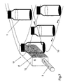
- FIG. 8 on-line analysis of aggregates in syringes
- FIG. 9 on-line analysis of aggregates in horizontally positioned syringes
- FIG. 10 a spectrofluorimeter arrangement
- FIG. 11 a flow-through device for liquid chromatography
- FIG. 12 a flow-through device for liquid chromatography with fluorescence detection
- FIG. 13 a flow-through device as part of a scattering detector
- FIG. 14 a device containing fluorescence and UV spectrometer to be placed on a scanner surface
- a highly focussed light beam such as the beam of lasers, nano-LEDs etc. is used for excitation and visualization of particles in solutions.
- the use of a laser beam together with the magnification of the image by the scanner permits the visualization and analysis of particles that scatter the laser beam in the solution. Parameters like size, morphology and number of particles of defined size such as protein aggregates and/or leachables in a given volume can be determined. Red lasers are preferred for the detection of larger particles, whereas the use of green and blue lasers permits detection of smaller particles.
- Containers 1 such as vials, cuvettes, multiple well plates such as micro-titer plates, syringes etc. containing sample solutions to be analyzed are positioned on or adjacent the surface of a flat bed scanner 2 and exposed to a laser beam 4 generated by a laser 3 located at the side of the scanner.
- a vial is positioned horizontally on the scanner bed and beam 4 emitted by laser 3 enters the vial through its bottom. If the solution contained in the vial is contaminated with particles the laser beam is scattered. Scattering is effected by each individual particle in the solution.
- the optical effect generated by the scattering of the laser beam or, in other words, the image of the beam in the solution is digitally scanned resulting in the image 5 shown below the scanner.
- Electronic magnification results in a magnified image 6 showing individual particles.
- the particles may be analyzed by counting, classification by size, morphology, size distribution etc.
- the vials 1 may also be standing on the scanner bed 2 .
- the laser beam 4 emitted by laser 3 enters the solution through the side wall of the vial.
- an array of two or more lasers 3 is arranged to emit beams 4 , preferably of different color, into or through the sample container 1 as shown in FIG. 3
- a number of containers 1 which may also be of different type such as vials, cuvettes etc. are arranged in a sample chamber 7 in the shape of a frame positioned on a scanner surface 2 .
- An array of lasers 3 emits laser beams 4 for simultaneously analyzing vials or sample cuvettes 1 located in the sample chamber.
- FIG. 5 An alternative possibility is shown in FIG. 5 where a number of vials 1 positioned on a scanner surface 2 are simultaneously exposed to one laser beam 4 .
- the use of laser excitation may be combined with fluorescence spectroscopy.
- a laser beam 4 emitted by a laser 3 is directed through a sample container 1 positioned on a scanner surface 2 .
- Simultaneously excitation light 8 which may be transmitted by fiber optics from a spectrofluorimeter is guided into the sample and fluorescence light is received by a detector which may be fiber optics to the spectrofluorimeter.
- Vials 1 containing a product are moving along a production line 10 indicated schematically. The direction of movement is shown by arrows.
- a measuring station 11 the vials pass in front of a vertically positioned scanner surface 12 . While the vials pass the scanner they are exposed to a laser 4 emitted by a laser 3 located at the side of the line.
- FIG. 8 shows a similar use for the detection of particles in pre-filled syringes 13 passing by a similar measuring station 11 where they are exposed to a beam 4 emitted by a laser 3 .
- the laser beam 4 made visible by particulate matter in the solution is scanned by vertically arranged scanner 12 . If particles such as protein aggregates and/or leachables are detected the vials or syringes are automatically separated.
- the syringes 13 may also be transported lying on a belt 14 which moves over the scanner surface 2 .
- a laser 3 is positioned at the side of the moving belt to emit a beam 4 which passes through the solution in the syringe.
- FIG. 10 shows equipment to be inserted in cuvette holder 15 for measuring fluorescence.
- a small vertical scanner is arranged at the side of the sample holding surface.
- a laser is positioned to emit a beam parallel to the scanner surface.
- a fluorescence excitation light source 16 is arranged opposite the laser and a detector 17 which may be fiber optics transmitting the fluorescence light to a spectrofluorimeter is arranged angularly displaced from the excitation beam.
- Similar equipment of this type may be adapted to other spectroscopic methods such as UV-VIS, circular dichroism, infrared or Raman spectrometry
- the fluorescence excitation frequently generates a visible effect in the sample which may also be recorded by the scanner even without a laser beam. Accordingly, the combination of a scanner with fluorescence measurement equipment is also one aspect of the present invention.
- FIG. 11 A further embodiment of the invention shown in FIG. 11 is a flow-through device 18 for online characterization of aggregates in different liquid chromatographic methods such as: size exclusion (SEC), high pressure liquid chromatography (HPLC), field flow fractionation (FFF), ion exchange chromatography, iso-electric focusing, or capillary zone electrophoresis (CZE).
- FIG. 12 shows the same arrangement with additional fluorescence measurement equipment as in the embodiment shown in FIG. 10 .
- the online equipment may incorporate other detections such as fluorescence, UV, dynamic or static light scattering.
- FIG. 13 shows the use of a laser and scanner as a part of a known dynamic or static light-scattering detector 19 having a flow-through capillary 20 .
- the use of the visual scanner permits the analysis of large particles.
- the scanner 2 is positioned underneath the light scattering detector 19 whereas the laser is arranged at the side thereof.
- the system is especially useful for chromatography techniques such as filed flow fractionation.
- the device shown in FIG. 14 is basically a box 21 to be placed on a scanner 2 . It has an opening 22 for inserting a sample cuvette 23 .
- the box contains a laser 24 arranged to direct a beam through the sample.
- the laser beam 25 is passing the sample parallel to the long side of the cuvette, but may also be directed under an angle, such as diagonal etc.
- a light source 26 emitting fluorescence excitation light such as from a spectrofluorimeter and UV-Vis monochromatic light.
- a fluorescence emission detector 27 is positioned above the cuvette.
- a UV-Vis absorption detector 28 is arranged. With minor adaptations this device could of course also be used for multiple well plates.
Abstract
A laser beam (4) is guided onto or through a sample (1) which while exposed to the laser is scanned by means of a digital scanner (2). The apparatus for performing this method comprises a laser light source (3) and a digital scanner (2).
Description
The invention relates to a method of detecting and storing information on properties of an analytical sample solution, especially a pharmaceutical preparation, by means of a digital scanning device and to an apparatus for performing this method.
Evaluation of analytical samples by means of a flat bed scanner or other electro-optical device is known. In WO 89/07255 extracting of information on chemical or biological assays or procedures, in particular the analysis of blood samples etc. by means of a flat bed scanner is disclosed. In US 2002/0168784 a diagnostic system using a flat bed scanner, especially determining and storing the result of agglutination assays is disclosed. The optical properties which are detected are fluorescence, colour, light scattering or characteristics of samples and resulting agglutinates.
For all these known methods the sample cuvettes, preferably in the form of micro titer plates are placed on the scanner bed and exposed to incident light.
It has been found that by exposing a sample to a laser beam optical effects are generated which contain information on the properties of the sample and that by digitally scanning the optical effects the information is stored and available for electronic evaluation.
Therefore, the invention is directed to an analytical method in which a laser beam is guided onto or through a sample which while exposed to the laser is scanned by means of a digital scanner. Further the invention is directed to an apparatus for performing this method comprising a light source positioned for guiding a laser beam onto or through a sample and a digital scanner arranged in a relative position to the sample for scanning the optical effect generated by the laser beam on or in the sample.
In the following preferred embodiments of the invention are described by reference to the accompanying drawings. It is shown in
In all embodiments of the invention described hereafter a highly focussed light beam such as the beam of lasers, nano-LEDs etc. is used for excitation and visualization of particles in solutions. The use of a laser beam together with the magnification of the image by the scanner permits the visualization and analysis of particles that scatter the laser beam in the solution. Parameters like size, morphology and number of particles of defined size such as protein aggregates and/or leachables in a given volume can be determined. Red lasers are preferred for the detection of larger particles, whereas the use of green and blue lasers permits detection of smaller particles.
As shown in FIG. 2 , the vials 1 may also be standing on the scanner bed 2. In this case the laser beam 4 emitted by laser 3 enters the solution through the side wall of the vial.
For detailed investigations an array of two or more lasers 3 is arranged to emit beams 4, preferably of different color, into or through the sample container 1 as shown in FIG. 3
As shown in FIG. 4 a number of containers 1 which may also be of different type such as vials, cuvettes etc. are arranged in a sample chamber 7 in the shape of a frame positioned on a scanner surface 2. An array of lasers 3 emits laser beams 4 for simultaneously analyzing vials or sample cuvettes 1 located in the sample chamber. An alternative possibility is shown in FIG. 5 where a number of vials 1 positioned on a scanner surface 2 are simultaneously exposed to one laser beam 4. These arrangements allow the simultaneous analysis of a great number of samples.
As shown in FIG. 6 the use of laser excitation may be combined with fluorescence spectroscopy. As in the examples described before a laser beam 4 emitted by a laser 3 is directed through a sample container 1 positioned on a scanner surface 2. Simultaneously excitation light 8, which may be transmitted by fiber optics from a spectrofluorimeter is guided into the sample and fluorescence light is received by a detector which may be fiber optics to the spectrofluorimeter.
As shown in FIG. 7 a preferred embodiment of the invention is useful for continuous online detection of aggregates in vials containing e.g. solutions of pharmaceutical products. Vials 1 containing a product are moving along a production line 10 indicated schematically. The direction of movement is shown by arrows. At a measuring station 11 the vials pass in front of a vertically positioned scanner surface 12. While the vials pass the scanner they are exposed to a laser 4 emitted by a laser 3 located at the side of the line.
As shown in FIG. 9 the syringes 13 may also be transported lying on a belt 14 which moves over the scanner surface 2. A laser 3 is positioned at the side of the moving belt to emit a beam 4 which passes through the solution in the syringe.
The fluorescence excitation frequently generates a visible effect in the sample which may also be recorded by the scanner even without a laser beam. Accordingly, the combination of a scanner with fluorescence measurement equipment is also one aspect of the present invention.
A further embodiment of the invention shown in FIG. 11 is a flow-through device 18 for online characterization of aggregates in different liquid chromatographic methods such as: size exclusion (SEC), high pressure liquid chromatography (HPLC), field flow fractionation (FFF), ion exchange chromatography, iso-electric focusing, or capillary zone electrophoresis (CZE). FIG. 12 shows the same arrangement with additional fluorescence measurement equipment as in the embodiment shown in FIG. 10 .
Beside the detection and visualization of the particles by the scanner the online equipment may incorporate other detections such as fluorescence, UV, dynamic or static light scattering.
The device shown in FIG. 14 is basically a box 21 to be placed on a scanner 2. It has an opening 22 for inserting a sample cuvette 23. The box contains a laser 24 arranged to direct a beam through the sample. The laser beam 25 is passing the sample parallel to the long side of the cuvette, but may also be directed under an angle, such as diagonal etc. Also contained and arranged at the side of the cuvette is a light source 26 emitting fluorescence excitation light such as from a spectrofluorimeter and UV-Vis monochromatic light. Above the cuvette a fluorescence emission detector 27 is positioned. And at the side opposite the light source a UV-Vis absorption detector 28 is arranged. With minor adaptations this device could of course also be used for multiple well plates.
Claims (10)
1. A method of determining parameters of individual contaminant particles contained in a given volume of a liquid solution in a container by means of a flat bed scanner, comprising the steps of
placing the container with the solution onto or close to the bed of the flat bed scanner,
guiding a laser beam through the container and the solution,
digitally scanning the container with the solution therein while exposed to the laser beam to excite and visualize the individual contaminant particles in the solution, and
producing an image of optical effects generated by the individual contaminant particles contained in the solution and scattering of the laser light, based on parameters of the individual contaminant particles in the solution, including size of the individual contaminant particles, morphology of the individual contaminant particles and number of the individual contaminant particles of a defined size in a given volume of the solution.
2. The method according to claim 1 , wherein several laser beams are guided through the solution.
3. The method according to claim 2 , wherein the laser beams are of different color.
4. The method according to claim 1 , wherein a laser beam is simultaneously directed through several containers.
5. The method according to claim 1 , wherein a fluorescence detection is combined with the laser excitation.
6. The method according to claim 1 , wherein the content of containers is analyzed on-line.
7. The method according to claim 1 , wherein the laser excitation is used in a flow-through arrangement.
8. An apparatus for performing the method according to any one of claims 1 -7 , comprising a light source positioned for guiding a laser beam onto or through a liquid solution in a container and a flat bed scanner arranged in a relative position to the sample for scanning the optical effect generated by the individual contaminant particles contained in the solution and scattering the laser light.
9. An apparatus for performing the method according to claim 1 , comprising a light source positioned for guiding a laser beam onto or through a liquid solution in a container and a flat bed scanner arranged in a relative position to the solution for scanning the optical effect generated by the laser beam on or in the solution.
10. The method according to claim 1 , wherein several laser beams are guided through the solution; and
wherein a fluorescence detection is combined with the laser excitation.
Applications Claiming Priority (1)
| Application Number | Priority Date | Filing Date | Title |
|---|---|---|---|
| PCT/CH2007/000025 WO2008086632A1 (en) | 2007-01-19 | 2007-01-19 | Method and apparatus for detecting and registering properties of samples |
Publications (2)
| Publication Number | Publication Date |
|---|---|
| US20100102247A1 US20100102247A1 (en) | 2010-04-29 |
| US9417176B2 true US9417176B2 (en) | 2016-08-16 |
Family
ID=38522765
Family Applications (1)
| Application Number | Title | Priority Date | Filing Date |
|---|---|---|---|
| US12/522,877 Active 2027-06-30 US9417176B2 (en) | 2007-01-19 | 2007-01-19 | Method and apparatus for detecting and registering properties of samples |
Country Status (7)
| Country | Link |
|---|---|
| US (1) | US9417176B2 (en) |
| EP (1) | EP2106541B1 (en) |
| JP (1) | JP2010516999A (en) |
| CN (1) | CN101583863A (en) |
| ES (1) | ES2662027T3 (en) |
| PL (1) | PL2106541T3 (en) |
| WO (1) | WO2008086632A1 (en) |
Families Citing this family (7)
| Publication number | Priority date | Publication date | Assignee | Title |
|---|---|---|---|---|
| PL2232700T3 (en) | 2007-12-21 | 2015-01-30 | Dts Llc | System for adjusting perceived loudness of audio signals |
| WO2010100501A1 (en) * | 2009-03-04 | 2010-09-10 | Malvern Instruments Limited | Particle characterization |
| US8538042B2 (en) | 2009-08-11 | 2013-09-17 | Dts Llc | System for increasing perceived loudness of speakers |
| US9312829B2 (en) | 2012-04-12 | 2016-04-12 | Dts Llc | System for adjusting loudness of audio signals in real time |
| US10132736B2 (en) * | 2012-05-24 | 2018-11-20 | Abbvie Inc. | Methods for inspection of protein particles in a liquid beneficial agent |
| BR112019008270A8 (en) * | 2016-10-28 | 2023-04-11 | Beckman Coulter Inc | SUBSTANCE PREPARATION EVALUATION SYSTEM |
| LU100777B1 (en) * | 2018-04-23 | 2019-10-23 | Cytena Gmbh | A method of assaying a liquid containing at least one cell and / or at least one particle |
Citations (12)
| Publication number | Priority date | Publication date | Assignee | Title |
|---|---|---|---|---|
| US3624835A (en) * | 1968-11-21 | 1971-11-30 | Science Spectrum | Microparticle analyzer employing a spherical detector array |
| US4221961A (en) * | 1978-10-23 | 1980-09-09 | Industrial Automation Corporation | Electronic bottle inspector having particle and liquid detection capabilities |
| WO1982000354A1 (en) | 1980-07-24 | 1982-02-04 | Oy Labsystems | Method and apparatus for the measurement of the properties of an agglutination |
| WO1989007255A1 (en) | 1988-02-03 | 1989-08-10 | Cetus Corporation | Apparatus and method for detecting hemagglutinaion reactions |
| DE4223269A1 (en) | 1992-07-16 | 1994-01-20 | Krieg Gunther | Identification of molecular compounds by absorption, scattering or fluorescence of liquids in returned drinks bottles - applying laser pulse to test container and separating into different spectral colours using bundle of optical fibres of different length before photomultiplier |
| US5436979A (en) * | 1992-08-21 | 1995-07-25 | Eastman Kodak Company | Process for detecting and mapping dirt on the surface of a photographic element |
| US5486693A (en) | 1994-02-17 | 1996-01-23 | Thermedics Detection Inc. | Detection of turbid contaminants in containers by detecting scattered radiant energy |
| GB2312505A (en) | 1996-04-23 | 1997-10-29 | Hitachi Ltd | Capillary array electrophoresis system |
| US6214560B1 (en) * | 1996-04-25 | 2001-04-10 | Genicon Sciences Corporation | Analyte assay using particulate labels |
| US20020063215A1 (en) | 2000-11-24 | 2002-05-30 | Kiyoshi Yagita | Impurities inspection system |
| US20020168784A1 (en) | 1998-07-23 | 2002-11-14 | Erling Sundrehagen | Agglutination assays |
| WO2006023470A1 (en) | 2004-08-19 | 2006-03-02 | Becton, Dickinson And Company | Apparatus for performing optical measurements on blood culture bottles |
Family Cites Families (8)
| Publication number | Priority date | Publication date | Assignee | Title |
|---|---|---|---|---|
| JP2667526B2 (en) * | 1989-08-12 | 1997-10-27 | 科学技術振興事業団 | High sensitivity multi-wavelength emission fluorescence spectroscopy method and apparatus |
| JPH03197840A (en) * | 1989-12-26 | 1991-08-29 | Canon Inc | Particle analyzing device |
| JP2826366B2 (en) * | 1990-04-12 | 1998-11-18 | 株式会社日立製作所 | Fluorescence detection type electrophoresis device |
| DK17791D0 (en) * | 1991-02-01 | 1991-02-01 | Novo Nordisk As | CONTAINER INSPECTION |
| JPH0572179A (en) * | 1991-09-10 | 1993-03-23 | Hitachi Ltd | Detecting device for two-dimensional fluorescent image of nucleic acid and protein |
| US6914250B2 (en) * | 1997-03-07 | 2005-07-05 | Clare Chemical Research, Inc. | Fluorometric detection using visible light |
| JP2002228586A (en) * | 2001-01-31 | 2002-08-14 | Hitachi Ltd | Fluorescence measuring instrument and fluorescence measuring method |
| US20030133119A1 (en) * | 2002-01-17 | 2003-07-17 | Bachur Nicholas R. | Rapid imaging of particles in a large fluid volume through flow cell imaging |
-
2007
- 2007-01-19 US US12/522,877 patent/US9417176B2/en active Active
- 2007-01-19 PL PL07700123T patent/PL2106541T3/en unknown
- 2007-01-19 CN CNA2007800499751A patent/CN101583863A/en active Pending
- 2007-01-19 ES ES07700123.8T patent/ES2662027T3/en active Active
- 2007-01-19 JP JP2009545784A patent/JP2010516999A/en active Pending
- 2007-01-19 EP EP07700123.8A patent/EP2106541B1/en not_active Not-in-force
- 2007-01-19 WO PCT/CH2007/000025 patent/WO2008086632A1/en active Application Filing
Patent Citations (13)
| Publication number | Priority date | Publication date | Assignee | Title |
|---|---|---|---|---|
| US3624835A (en) * | 1968-11-21 | 1971-11-30 | Science Spectrum | Microparticle analyzer employing a spherical detector array |
| US4221961A (en) * | 1978-10-23 | 1980-09-09 | Industrial Automation Corporation | Electronic bottle inspector having particle and liquid detection capabilities |
| WO1982000354A1 (en) | 1980-07-24 | 1982-02-04 | Oy Labsystems | Method and apparatus for the measurement of the properties of an agglutination |
| WO1989007255A1 (en) | 1988-02-03 | 1989-08-10 | Cetus Corporation | Apparatus and method for detecting hemagglutinaion reactions |
| DE4223269A1 (en) | 1992-07-16 | 1994-01-20 | Krieg Gunther | Identification of molecular compounds by absorption, scattering or fluorescence of liquids in returned drinks bottles - applying laser pulse to test container and separating into different spectral colours using bundle of optical fibres of different length before photomultiplier |
| US5436979A (en) * | 1992-08-21 | 1995-07-25 | Eastman Kodak Company | Process for detecting and mapping dirt on the surface of a photographic element |
| US5486693A (en) | 1994-02-17 | 1996-01-23 | Thermedics Detection Inc. | Detection of turbid contaminants in containers by detecting scattered radiant energy |
| GB2312505A (en) | 1996-04-23 | 1997-10-29 | Hitachi Ltd | Capillary array electrophoresis system |
| US5938908A (en) * | 1996-04-23 | 1999-08-17 | Hitachi, Ltd. | Capillary array electrophoresis system |
| US6214560B1 (en) * | 1996-04-25 | 2001-04-10 | Genicon Sciences Corporation | Analyte assay using particulate labels |
| US20020168784A1 (en) | 1998-07-23 | 2002-11-14 | Erling Sundrehagen | Agglutination assays |
| US20020063215A1 (en) | 2000-11-24 | 2002-05-30 | Kiyoshi Yagita | Impurities inspection system |
| WO2006023470A1 (en) | 2004-08-19 | 2006-03-02 | Becton, Dickinson And Company | Apparatus for performing optical measurements on blood culture bottles |
Non-Patent Citations (3)
| Title |
|---|
| Capelle, Martinus et al., "High throughput screening of protein formulation stability: Practical considerations" European Journal of Pharmaceutics and Biopharmaceutics, vol. 65, Jan. 5, 2007, pp. 131-148. |
| Demeule, Barthelemy et al., "Characterization of protein aggregation: The case of a therapeutic immunoglobulin", Biochemica et Biophysica Acta (BBA)-Proteins & Proteomics, vol. 1774, No. 1, Jan. 9, 2007, pp. 146-153. |
| International Search Report dated Oct. 1, 2007 for the corresponding International Application No. PCT/CH2007/000025 (Publication No. WO 2008/086632 A1). |
Also Published As
| Publication number | Publication date |
|---|---|
| EP2106541B1 (en) | 2017-12-13 |
| WO2008086632A8 (en) | 2009-08-13 |
| WO2008086632A1 (en) | 2008-07-24 |
| EP2106541A1 (en) | 2009-10-07 |
| JP2010516999A (en) | 2010-05-20 |
| ES2662027T3 (en) | 2018-04-05 |
| PL2106541T3 (en) | 2018-05-30 |
| CN101583863A (en) | 2009-11-18 |
| US20100102247A1 (en) | 2010-04-29 |
Similar Documents
| Publication | Publication Date | Title |
|---|---|---|
| US9417176B2 (en) | Method and apparatus for detecting and registering properties of samples | |
| EP2948756B1 (en) | Optical measuring apparatus and method for the analysis of samples contained in liquid drops | |
| CN102027350B (en) | Method for measuring the area of a sample disposed within an analysis chamber | |
| Bloomfield et al. | Non-invasive identification of incoming raw pharmaceutical materials using Spatially Offset Raman Spectroscopy | |
| JP5174035B2 (en) | 2D array imaging | |
| JP2008281571A (en) | Apparatus for reading signals generated from resonance lightscattered particle labels | |
| US20190170642A1 (en) | Array based sample characterization | |
| US9488579B2 (en) | Optical measuring apparatus and method for the analysis of samples contained in liquid drops | |
| JP2007535671A (en) | Apparatus and method for inspecting material flow by light scattering inside the material | |
| US9488576B2 (en) | Optical measuring apparatus and method for the analysis of samples contained in liquid drops | |
| US20220326129A1 (en) | Systems and methods for identifying protein aggregates in biotherapeutics | |
| US20230417676A1 (en) | Biological analysis devices and systems | |
| US20220299436A1 (en) | Microscopy unit | |
| KR102441156B1 (en) | multiplexing analyzing apparatus using muiti-wavelength light | |
| JPS6244647A (en) | Flow cell for measuring particle characteristic | |
| CN113272060A (en) | Compact imaging-based sensor |
Legal Events
| Date | Code | Title | Description |
|---|---|---|---|
| STCF | Information on status: patent grant |
Free format text: PATENTED CASE |
|
| MAFP | Maintenance fee payment |
Free format text: PAYMENT OF MAINTENANCE FEE, 4TH YR, SMALL ENTITY (ORIGINAL EVENT CODE: M2551); ENTITY STATUS OF PATENT OWNER: SMALL ENTITY Year of fee payment: 4 |
|
| FEPP | Fee payment procedure |
Free format text: MAINTENANCE FEE REMINDER MAILED (ORIGINAL EVENT CODE: REM.); ENTITY STATUS OF PATENT OWNER: SMALL ENTITY |