US9414724B2 - Damped hinge assemblies - Google Patents

Damped hinge assemblies Download PDF

Info

Publication number
US9414724B2
US9414724B2 US13/817,566 US201113817566A US9414724B2 US 9414724 B2 US9414724 B2 US 9414724B2 US 201113817566 A US201113817566 A US 201113817566A US 9414724 B2 US9414724 B2 US 9414724B2
Authority
US
United States
Prior art keywords
damper
linear
damped
pivotal movement
hinge assembly
Prior art date
Legal status (The legal status is an assumption and is not a legal conclusion. Google has not performed a legal analysis and makes no representation as to the accuracy of the status listed.)
Expired - Fee Related
Application number
US13/817,566
Other versions
US20130283568A1 (en
Inventor
William Earnest Taylor Vallance
David Pecar
Current Assignee (The listed assignees may be inaccurate. Google has not performed a legal analysis and makes no representation or warranty as to the accuracy of the list.)
Titus International Ltd
Original Assignee
Titus International Ltd
Priority date (The priority date is an assumption and is not a legal conclusion. Google has not performed a legal analysis and makes no representation as to the accuracy of the date listed.)
Filing date
Publication date
Application filed by Titus International Ltd filed Critical Titus International Ltd
Assigned to TITUS INTERNATIONAL LTD. reassignment TITUS INTERNATIONAL LTD. ASSIGNMENT OF ASSIGNORS INTEREST (SEE DOCUMENT FOR DETAILS). Assignors: PECAR, DAVID, VALLANCE, WILLIAM ERNEST TAYLOR
Publication of US20130283568A1 publication Critical patent/US20130283568A1/en
Application granted granted Critical
Publication of US9414724B2 publication Critical patent/US9414724B2/en
Expired - Fee Related legal-status Critical Current
Anticipated expiration legal-status Critical

Links

Images

Classifications

    • AHUMAN NECESSITIES
    • A47FURNITURE; DOMESTIC ARTICLES OR APPLIANCES; COFFEE MILLS; SPICE MILLS; SUCTION CLEANERS IN GENERAL
    • A47KSANITARY EQUIPMENT NOT OTHERWISE PROVIDED FOR; TOILET ACCESSORIES
    • A47K13/00Seats or covers for all kinds of closets
    • A47K13/12Hinges
    • EFIXED CONSTRUCTIONS
    • E05LOCKS; KEYS; WINDOW OR DOOR FITTINGS; SAFES
    • E05FDEVICES FOR MOVING WINGS INTO OPEN OR CLOSED POSITION; CHECKS FOR WINGS; WING FITTINGS NOT OTHERWISE PROVIDED FOR, CONCERNED WITH THE FUNCTIONING OF THE WING
    • E05F3/00Closers or openers with braking devices, e.g. checks; Construction of pneumatic or liquid braking devices
    • E05F3/20Closers or openers with braking devices, e.g. checks; Construction of pneumatic or liquid braking devices in hinges
    • E05Y2900/614
    • EFIXED CONSTRUCTIONS
    • E05LOCKS; KEYS; WINDOW OR DOOR FITTINGS; SAFES
    • E05YINDEXING SCHEME ASSOCIATED WITH SUBCLASSES E05D AND E05F, RELATING TO CONSTRUCTION ELEMENTS, ELECTRIC CONTROL, POWER SUPPLY, POWER SIGNAL OR TRANSMISSION, USER INTERFACES, MOUNTING OR COUPLING, DETAILS, ACCESSORIES, AUXILIARY OPERATIONS NOT OTHERWISE PROVIDED FOR, APPLICATION THEREOF
    • E05Y2999/00Subject-matter not otherwise provided for in this subclass
    • Y10T16/2771
    • Y10T16/538

Definitions

  • This invention relates to damped hinge assemblies and more particularly, though not exclusively, to damped hinge assemblies for mounting elements such as lids, seats and doors.
  • the invention provides a damped hinge assembly for mounting a first member for pivotal movement relative to a second member about an axis of rotation.
  • the assembly comprises a linear damper, means mounting the damper with its longitudinal axis parallel to the hinge axis, and camrning means for converting pivotal movement of the first member in at least one direction of rotation into linear displacement of the damper to cause the damper to produce a damped resistive force to counter said pivotal movement of the first member.
  • the longitudinal axis of the damper is arranged to be coincident with the hinge axis.
  • FIG. 1 shows a first form of a damped hinge assembly according to the invention (shown partly cut-away to reveal detail),
  • FIG. 2 is a detail view of the drive mechanism of the assembly of FIG. 1 ,
  • FIG. 3 is an exploded view of the FIG. 2 detail
  • FIG. 4 shows a second form of a damped hinge assembly according to the invention (shown partly cut-away to reveal detail),
  • FIGS. 5 and 6 show in partly cut-away detail the damping unit of the assembly of FIG. 4 .
  • FIG. 7 shows in partly cut-away detail an alternative form of a damping unit for the assembly of FIG. 4 .
  • the damped hinge assembly seen in FIG. 1 is for use on a lavatory seat 11 .
  • the lavatory seat 11 comprises a lid member 12 and a seat member 13 , both of which are pivotally mounted onto the lavatory 14 by a hinge mounted on a block 22 (shown partly cut away in the drawings).
  • the block 22 is anchored to the lavatory 14 by the usual spaced apart threaded fasteners 16 .
  • the arrangement enables both the lid and seat members 12 , 13 to be pivotable between a lower, generally horizontal position resting on the lavatory 14 and a raised position, generally slightly beyond vertical and resting against a cistern or wall or the like.
  • the assembly is arranged to provide a damped resistive force to counter the pivotal movement of both the lid and seat members 12 , 13 as they move under gravity from their raised position to their lowered position. This is intended to avoid possible damage that could otherwise occur if the lid and/or seat members were accidentally allowed to fall freely onto the lavatory.
  • the assembly comprises a damper 17 , which is conveniently located in the space between the hinge block mounting threaded fasteners 16 .
  • the damper 17 here is a linear damper of the piston and cylinder variety, with a piston (not shown) connected to a piston rod 18 and acting within a cylinder 19 on a damping medium (not shown) such as silicone (see FIG. 3 ).
  • the damper 17 incorporates a spring (not shown) arranged to bias the piston rod 18 towards its extended position.
  • the damper 17 is designed here to provide the damped resistive force to the lid and/or seat members 12 , 13 in response to its axial compression. However, the damper 17 provides no damped resistance upon its axial extension.
  • the damper 17 is mounted on the block 22 and arranged with its longitudinal axis coincident with the pivotal axis 20 of the assembly.
  • the damper 17 is captured in this position between two spaced apart end caps 21 a , 21 b .
  • Each end cap 21 a , 21 b is generally cylindrical and has an axially extending rib 23 a , 23 b which engages in a groove 24 in the block 22 .
  • the groove 24 extends parallel to the pivotal axis 20 of the assembly.
  • the arrangement means that the two end caps 21 a , 21 b are both capable of linear movement parallel to the pivotal axis 20 of the assembly (both towards and away from each other), but are prevented from rotating relative to the block 22 .
  • the lid and seat members 12 , 13 each have a respective driving element 30 a , 30 b associated therewith.
  • Each driving element 30 a , 30 b is rotatably mounted on the assembly by a spindle 31 a , 31 b journalled in a bore in the block 22 .
  • the axis of rotation of the spindles 31 a , 31 b is coincident with the pivotal axis 20 of the assembly.
  • Each driving element 30 a , 30 b is arranged to be keyed to its respective lid/seat member 12 , 13 to rotate therewith.
  • the spindle 31 a of its respective driving element 30 a is provided with flats 37 a and fits in a flatted hole 36 in the hinge part of the lid member.
  • the arrangement means that whenever the lid member 12 is pivoted, the spindle 31 a and hence its associateda driving element 30 a will likewise be driven to rotate.
  • the spindle 31 b is provided with flats 37 b and fits in a flatted hole in the hinge part of the seat member 13 , so that whenever the seat member is pivoted, the spindle 31 b and hence its associated driving element 30 b will likewise be driven to rotate.
  • Each driving element 30 a , 30 b has circumferentially extending ramped surfaces 34 a , 34 b on its axially inwardly facing end.
  • the ramped surfaces are provided on their elements as diametrically opposed pairs, as can be seen in the case of the driving element 30 b for the seat member in FIG. 3 .
  • Each of these ramped surfaces 34 a , 34 b is engaged by a respective nib 35 a , 35 b on the end caps 21 a , 21 b (again provided as diametrically opposed pairs).
  • the nibs 35 a , 35 b will be biassed into engagement with their respective ramped surfaces 34 a , 34 b by the action of the spring in the damper 17 .
  • this arrangement means that when either of the driving elements 30 a , 30 b rotates, its ramped surface 34 a , 34 b will act on the respective nib 35 a , 35 b to cause longitudinal displacement of its respective end cap 21 a , 21 b .
  • the ramped surfaces 34 a , 34 b and nibs 35 a , 35 b thus act in the manner of a cam and cam follower, translating rotational movement into linear movement.
  • the rotational movement of the lid and/or seat members 12 , 13 is thus translated by this motion converting mechanism into linear displacement (extension or compression) of the damper 17 .
  • the assembly is seen in its condition when the lid member is in its raised position, whilst the seat member is in its lower position.
  • the driving element 30 b associated with the seat member has been rotated in the direction of arrow A as the seat member has been lowered.
  • This has driven its associated end cap 21 b in the direction of arrow B by the caroming action of the ramped surface 34 b on the nib 35 b . Movement of the end cap 21 b in this manner has caused compression of the damper 17 , thereby imparting a damped resistive force to the lowering movement of the seat member.
  • the manner of engagement of the nibs 35 a , 35 b on their respective ramped surfaces 34 a , 34 b needs to be capable of sliding contact. This can be achieved by conveniently making the components of the assembly of moulded plastics material. It will also be understood that the nibs 35 a , 35 b engage their respective ramped surfaces 34 a , 34 b over a discrete and relatively small contact area. This allows the possibility for the profile of the ramped surfaces 34 a , 34 b to be configured in an almost infinite variety of different ways in order to suit different requirements.
  • the ramped surfaces 34 a , 34 b on the driving elements 30 a , 30 b are configured such that pivotal movement of the lid and/or seat members 12 , 13 in their lowering direction will cause linear movement of the end caps 21 a , 21 b in a direction towards each other. The effect of this will be to cause axial compression of the damper 17 . Axial compression of the damper 17 will in turn create a resistive damping force which is transmitted back through the drive mechanism to the lid and/or seat members 12 , 13 and hence attenuate their closing movement.
  • damper 17 will be actuated to provide a damped resistive force to the closing movement of the lid or seat members 12 , 13 moving singly, as well as to the closing movement of the two members moving together.
  • the effect of the force of gravity acting on the lid and seat members 12 , 13 will not be constant throughout their pivotal movement. In fact, the force will increase progressively as the lid/seat members 12 , 13 pivot from their initial generally upright position towards their lower, generally horizontal position.
  • the assembly will be tailored to accommodate this variable force. This can be achieved in the assembly here by suitably configuring the profile of the ramped surfaces 34 a , 34 b on the driving elements 30 a , 30 b .
  • the amount of resistive damping force that the damper 17 generates is basically proportional to the rate of its axial compression: a higher rate of compression produces a larger damped resistive force and vice versa.
  • the ramped surfaces 34 a , 34 b on the driving elements 30 a , 30 b follow a plain helical pattern, this will produce a constant amount of linear displacement of the end caps 21 a , 21 b per degree of rotation of the driving elements, i.e. a constant rate of axial compression of the damper 17 . If the ramped surfaces 34 a , 34 b are instead configured to have an increasingly steep profile beyond helical, then this will cause an increasingly rapid rate of axial compression of the damper 17 per degree of rotation of the driving elements 30 a , 30 b .
  • the damped resistive force from the assembly can thus be matched to the variable load from the lid/seat members.
  • the profiling of the ramped surfaces 34 a , 34 b can also be configured to determine the precise range of rotational movement of the lid and seat members 12 , 13 during which the damper is to provide damped resistance. For example, it might typically be preferred for there to be no damping force during the first 20 o of the initial rotational movement of the lid and seat members from their upright position towards their lower position. In that case, each ramped surface 34 a , 34 b would be configured with an initial section of its profile lying normal to the pivotal axis 20 .
  • the assembly will normally be designed not to impart any damping force to oppose the opening movement of the seat and lid members upwardly from their lower position.
  • the damper may incorporate a valve mechanism in its piston.
  • damper it is not essential for the damper to incorporate a spring: an alternative mechanism could be provided for urging the damper towards its extended position.
  • the free end of the piston rod could be attached to the surface against which it is arranged to act.
  • damper In the assembly described above, although the damper is conveniently located within it, there is nevertheless enough room to fit in a unit with a sizeable damping capacity. If necessary, however, the damper could be augmented by one or more additional dampers mounted in parallel.
  • the assembly could be designed to accommodate two separate dampers aligned along the pivotal axis.
  • the dampers could be arranged to react against a common fixed point in the assembly, for example in the form of a central wall within the block.
  • Each of the dampers would then separately serve a respective one of the seat and lid members.
  • FIG. 4 shows a second form of damped hinge assembly, again for use on a lavatory seat 11 comprising a lid member 12 and a seat member 13 , both of which are pivotally mounted onto a lavatory 14 .
  • the pivotal mounting of the lid and seat members 12 , 13 comprises a pair of separate mounting units 50 a , 50 b .
  • the mounting units 50 a , 50 b are anchored to the lavatory 14 by threaded fasteners 16 located in the usual spaced apart mounting holes.
  • the mounting units 50 a , 50 b are essentially identical, and each comprises a block 51 a , 51 b (shown partly cut away) which is effectively fixed to the lavatory 14 .
  • a hinge damper unit 52 In each block 51 a , 51 b , there is mounted a hinge damper unit 52 .
  • the pair of hinge damper units 52 together provide a dual function: firstly, they provide a pivotal mounting for the lid and seat elements 12 , 13 , and, secondly, they provide a resistive damping force to their closing movement.
  • each hinge damper unit 52 is seen in more detail in FIGS. 5 and 6 and consists of a housing 53 , a damper 54 and a drive cap 55 .
  • the housing 53 has an externally splined section 56 by which it can be mounted to the block 51 a , 51 b : this holds the housing non-rotatably fixed to the block.
  • the housing 53 has a plain cylindrical surface 57 : this acts as a spindle for the pivotal mounting of one of the lid and seat elements 12 , 13 .
  • the housing 53 is closed off at one end by an end wall 58 .
  • the drive cap 55 is mounted at the other end of the housing 53 .
  • the drive cap 55 is mounted to be rotatable relative to the housing 53 , but is flanged (as at 59 ) to be retained axially in position relative to the housing.
  • the drive cap 55 is provided with splines 60 .
  • the drive cap 55 acts as a pivotal mounting for the other of the lid and seat elements 12 , 13 .
  • the splines 60 on the drive cap 55 ensure that the connection between the two is non-rotatable, ie when the lid or seat element to which it is connected is pivoted, it will cause a corresponding rotational movement of the drive cap 55 .
  • the drive cap 55 is provided with a pair of diametrically opposed keyways 61 .
  • the damper 54 here is again of the linear piston and cylinder variety, with a piston (not shown) connected to a piston rod 62 and acting within a cylinder 63 on a damping medium such as silicone, and with a spring (not shown) biassing the piston rod towards its extended position.
  • the free end of the piston rod 62 is arranged to abut against the end wall 58 of the housing 53 .
  • the spring is again not essential here, and the piston rod 62 could be attached to the end wall 58 of the housing 53 .
  • the cylinder 63 has a specially shaped external profile. At its end opposite its piston rod 62 , it has a pair of diametrically opposed keys 64 .
  • the keys 64 are designed to engage the keyways 61 of the drive cap 55 . This ensures that the cylinder 63 and drive cap 55 will rotate together, whilst allowing relative axial movement between the two.
  • the cylinder 63 also comprises a pair of diametrically opposed ribs 65 , each extending around its outer surface.
  • Each rib 65 is shaped with a camming profile that is designed to engage with a respective one of a pair of diametrically opposed lugs 66 provided on the interior of the housing 53 .
  • the ribs 65 and their respective lugs 66 cooperate together in the manner of a cam and cam follower and act to convert rotational movement of the drive cap 55 into axial displacement of the cylinder 63 .
  • With the piston rod 62 abutting against the end wall 58 of the housing 53 axial displacement of the cylinder 63 will cause extension or contraction of the damper 54 .
  • the damper 54 will be designed to produce a damped restrictive force on contraction, but no resistance on extension (it may incorporate a valve in its piston for this purpose).
  • the assembly can be set up to provide a damped resistive force to the pivotal closing movement of the lid/seat element, without resistance to its opening movement.
  • the assembly is arranged so that the hinge damper unit in one of the blocks will provide damping for one of the lid and seat elements, whilst the hinge damper unit in the other block will provide damping for the other element. It will be noted that this conveniently does not require the hinge damper unit to be separately handed: the same device can be used in each case.
  • this form of assembly can be designed to produce a tailored damped resistive force.
  • the nature of the rib/lug engagement between the cylinder 63 and housing 53 is designed to allow for the possibility of varying the camming profile. With a strictly helical camming profile, for example, this would produce a constant amount of axial displacement of the cylinder 63 per degree of rotation of the drive cap 55 . If the camming profile is designed to increase progressively from the helical, then this would produce an increasing amount of axial displacement per degree of rotation. Also, the starting point of the camming profile could be adjusted in order to delay the onset of the axial displacement until after a certain amount of rotation. Other variations of the camming profile are of course possible to allow a wide range of different solutions tailored to suit different applications.
  • the motion converting mechanism described above could be embodied in a number of different ways.
  • the camming profile could instead be provided in the form of grooves or cut-aways formed in the surface of the cylinder.
  • An example of this alternative form is seen in FIG. 7 .
  • a pair of diametrically opposed rebates 70 is formed in the outer surface of the cylinder 63 .
  • the housing 53 here is formed with a pair of diametrically opposed lugs 71 which extend into its interior and engage complementarily with respective rebates.
  • the assemblies described above are suitable for use in other applications, including for example in vertical alignment for hanging doors.
  • the assemblies could be used in the manner of a rising butt hinge and provide damping to the movement of the door as it falls and closes under the force of gravity.
  • the assemblies could be used in the manner of a normal swinging hinge and provide a damped resistive force to the closing movement of the door.

Landscapes

  • Health & Medical Sciences (AREA)
  • Public Health (AREA)
  • Pivots And Pivotal Connections (AREA)

Abstract

A damped hinge assembly mounts a first member (12, 13) for pivotal movement relative to a second member (14) about an axis of rotation (20). The assembly includes a linear damper (17), which is mounted with its longitudinal axis parallel to the hinge axis, and a cam drive arrangement (21 a, 21 b, 30 a, 30 b) for converting the pivotal movement of the first member in at least one direction of rotation into linear displacement of the damper. This causes the damper to produce a damped resistive force to counter the pivotal movement of the first member. The longitudinal axis of the damper is arranged to be coincident with the hinge axis.

Description

This invention relates to damped hinge assemblies and more particularly, though not exclusively, to damped hinge assemblies for mounting elements such as lids, seats and doors.
The invention provides a damped hinge assembly for mounting a first member for pivotal movement relative to a second member about an axis of rotation. The assembly comprises a linear damper, means mounting the damper with its longitudinal axis parallel to the hinge axis, and camrning means for converting pivotal movement of the first member in at least one direction of rotation into linear displacement of the damper to cause the damper to produce a damped resistive force to counter said pivotal movement of the first member. The longitudinal axis of the damper is arranged to be coincident with the hinge axis.
By way of example, embodiments of the invention will now be described with reference to the accompanying drawings, in which:
FIG. 1 shows a first form of a damped hinge assembly according to the invention (shown partly cut-away to reveal detail),
FIG. 2 is a detail view of the drive mechanism of the assembly of FIG. 1,
FIG. 3 is an exploded view of the FIG. 2 detail,
FIG. 4 shows a second form of a damped hinge assembly according to the invention (shown partly cut-away to reveal detail),
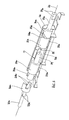
FIGS. 5 and 6 show in partly cut-away detail the damping unit of the assembly of FIG. 4, and
FIG. 7 shows in partly cut-away detail an alternative form of a damping unit for the assembly of FIG. 4.
The damped hinge assembly seen in FIG. 1 is for use on a lavatory seat 11. The lavatory seat 11 comprises a lid member 12 and a seat member 13, both of which are pivotally mounted onto the lavatory 14 by a hinge mounted on a block 22 (shown partly cut away in the drawings). The block 22 is anchored to the lavatory 14 by the usual spaced apart threaded fasteners 16. The arrangement enables both the lid and seat members 12, 13 to be pivotable between a lower, generally horizontal position resting on the lavatory 14 and a raised position, generally slightly beyond vertical and resting against a cistern or wall or the like.
The assembly is arranged to provide a damped resistive force to counter the pivotal movement of both the lid and seat members 12, 13 as they move under gravity from their raised position to their lowered position. This is intended to avoid possible damage that could otherwise occur if the lid and/or seat members were accidentally allowed to fall freely onto the lavatory.
The assembly comprises a damper 17, which is conveniently located in the space between the hinge block mounting threaded fasteners 16. The damper 17 here is a linear damper of the piston and cylinder variety, with a piston (not shown) connected to a piston rod 18 and acting within a cylinder 19 on a damping medium (not shown) such as silicone (see FIG. 3). The damper 17 incorporates a spring (not shown) arranged to bias the piston rod 18 towards its extended position. The damper 17 is designed here to provide the damped resistive force to the lid and/or seat members 12, 13 in response to its axial compression. However, the damper 17 provides no damped resistance upon its axial extension.
As will be seen in the drawings, the damper 17 is mounted on the block 22 and arranged with its longitudinal axis coincident with the pivotal axis 20 of the assembly. The damper 17 is captured in this position between two spaced apart end caps 21 a, 21 b. Each end cap 21 a, 21 b is generally cylindrical and has an axially extending rib 23 a, 23 b which engages in a groove 24 in the block 22. The groove 24 extends parallel to the pivotal axis 20 of the assembly. The arrangement means that the two end caps 21 a, 21 b are both capable of linear movement parallel to the pivotal axis 20 of the assembly (both towards and away from each other), but are prevented from rotating relative to the block 22. Thus, movement of the end caps 21 a, 21 b towards each other will cause axial compression of the damper 17, whilst movement of the end caps 21 a, 21 b away from each other will allow axial extension of the damper, under the influence of its spring.
As will be seen in the drawings, the lid and seat members 12, 13 each have a respective driving element 30 a, 30 b associated therewith. Each driving element 30 a, 30 b is rotatably mounted on the assembly by a spindle 31 a, 31 b journalled in a bore in the block 22. The axis of rotation of the spindles 31 a, 31 b is coincident with the pivotal axis 20 of the assembly. Each driving element 30 a, 30 b is arranged to be keyed to its respective lid/ seat member 12, 13 to rotate therewith. In the case of the lid member 12, for example, it can be seen in the drawings how the spindle 31 a of its respective driving element 30 a is provided with flats 37 a and fits in a flatted hole 36 in the hinge part of the lid member. The arrangement means that whenever the lid member 12 is pivoted, the spindle 31 a and hence its associateda driving element 30 a will likewise be driven to rotate. In a similar manner, the spindle 31 b is provided with flats 37 b and fits in a flatted hole in the hinge part of the seat member 13, so that whenever the seat member is pivoted, the spindle 31 b and hence its associated driving element 30 b will likewise be driven to rotate.
Each driving element 30 a, 30 b has circumferentially extending ramped surfaces 34 a, 34 b on its axially inwardly facing end. For balance, the ramped surfaces are provided on their elements as diametrically opposed pairs, as can be seen in the case of the driving element 30 b for the seat member in FIG. 3. Each of these ramped surfaces 34 a, 34 b is engaged by a respective nib 35 a, 35 b on the end caps 21 a, 21 b (again provided as diametrically opposed pairs). The nibs 35 a, 35 b will be biassed into engagement with their respective ramped surfaces 34 a, 34 b by the action of the spring in the damper 17. It will be understood that this arrangement means that when either of the driving elements 30 a, 30 b rotates, its ramped surface 34 a, 34 b will act on the respective nib 35 a, 35 b to cause longitudinal displacement of its respective end cap 21 a, 21 b. The ramped surfaces 34 a, 34 b and nibs 35 a, 35 b thus act in the manner of a cam and cam follower, translating rotational movement into linear movement. The rotational movement of the lid and/or seat members 12, 13 is thus translated by this motion converting mechanism into linear displacement (extension or compression) of the damper 17.
In FIG. 2, for example, the assembly is seen in its condition when the lid member is in its raised position, whilst the seat member is in its lower position. The driving element 30 b associated with the seat member has been rotated in the direction of arrow A as the seat member has been lowered. This has driven its associated end cap 21 b in the direction of arrow B by the caroming action of the ramped surface 34 b on the nib 35 b. Movement of the end cap 21 b in this manner has caused compression of the damper 17, thereby imparting a damped resistive force to the lowering movement of the seat member.
It will be understood that the manner of engagement of the nibs 35 a, 35 b on their respective ramped surfaces 34 a, 34 b needs to be capable of sliding contact. This can be achieved by conveniently making the components of the assembly of moulded plastics material. It will also be understood that the nibs 35 a, 35 b engage their respective ramped surfaces 34 a, 34 b over a discrete and relatively small contact area. This allows the possibility for the profile of the ramped surfaces 34 a, 34 b to be configured in an almost infinite variety of different ways in order to suit different requirements.
Here, the ramped surfaces 34 a, 34 b on the driving elements 30 a, 30 b are configured such that pivotal movement of the lid and/or seat members 12, 13 in their lowering direction will cause linear movement of the end caps 21 a, 21 b in a direction towards each other. The effect of this will be to cause axial compression of the damper 17. Axial compression of the damper 17 will in turn create a resistive damping force which is transmitted back through the drive mechanism to the lid and/or seat members 12, 13 and hence attenuate their closing movement.
It will be noted that the damper 17 will be actuated to provide a damped resistive force to the closing movement of the lid or seat members 12, 13 moving singly, as well as to the closing movement of the two members moving together.
The effect of the force of gravity acting on the lid and seat members 12, 13 will not be constant throughout their pivotal movement. In fact, the force will increase progressively as the lid/ seat members 12, 13 pivot from their initial generally upright position towards their lower, generally horizontal position. Ideally, the assembly will be tailored to accommodate this variable force. This can be achieved in the assembly here by suitably configuring the profile of the ramped surfaces 34 a, 34 b on the driving elements 30 a, 30 b. The amount of resistive damping force that the damper 17 generates is basically proportional to the rate of its axial compression: a higher rate of compression produces a larger damped resistive force and vice versa. If the ramped surfaces 34 a, 34 b on the driving elements 30 a, 30 b follow a plain helical pattern, this will produce a constant amount of linear displacement of the end caps 21 a, 21 b per degree of rotation of the driving elements, i.e. a constant rate of axial compression of the damper 17. If the ramped surfaces 34 a, 34 b are instead configured to have an increasingly steep profile beyond helical, then this will cause an increasingly rapid rate of axial compression of the damper 17 per degree of rotation of the driving elements 30 a, 30 b. The damped resistive force from the assembly can thus be matched to the variable load from the lid/seat members.
The profiling of the ramped surfaces 34 a, 34 b can also be configured to determine the precise range of rotational movement of the lid and seat members 12, 13 during which the damper is to provide damped resistance. For example, it might typically be preferred for there to be no damping force during the first 20 o of the initial rotational movement of the lid and seat members from their upright position towards their lower position. In that case, each ramped surface 34 a, 34 b would be configured with an initial section of its profile lying normal to the pivotal axis 20.
The assembly will normally be designed not to impart any damping force to oppose the opening movement of the seat and lid members upwardly from their lower position. For this purpose, the damper may incorporate a valve mechanism in its piston.
It is not essential for the damper to incorporate a spring: an alternative mechanism could be provided for urging the damper towards its extended position. In one example, the free end of the piston rod could be attached to the surface against which it is arranged to act.
In the assembly described above, although the damper is conveniently located within it, there is nevertheless enough room to fit in a unit with a sizeable damping capacity. If necessary, however, the damper could be augmented by one or more additional dampers mounted in parallel.
In a modified arrangement, the assembly could be designed to accommodate two separate dampers aligned along the pivotal axis. In that case, the dampers could be arranged to react against a common fixed point in the assembly, for example in the form of a central wall within the block. Each of the dampers would then separately serve a respective one of the seat and lid members. An advantage of this arrangement would be that the members will be able to experience the same level of damping force regardless of whether they are lowered separately or together. In the arrangement with just a single damper, the effect of the damping force will be less if the seat and lid members are lowered together than if they are lowered individually.
FIG. 4 shows a second form of damped hinge assembly, again for use on a lavatory seat 11 comprising a lid member 12 and a seat member 13, both of which are pivotally mounted onto a lavatory 14. In this case, the pivotal mounting of the lid and seat members 12, 13 comprises a pair of separate mounting units 50 a, 50 b. The mounting units 50 a, 50 b are anchored to the lavatory 14 by threaded fasteners 16 located in the usual spaced apart mounting holes.
The mounting units 50 a, 50 b are essentially identical, and each comprises a block 51 a, 51 b (shown partly cut away) which is effectively fixed to the lavatory 14. In each block 51 a, 51 b, there is mounted a hinge damper unit 52. As will be explained in more detail, the pair of hinge damper units 52 together provide a dual function: firstly, they provide a pivotal mounting for the lid and seat elements 12, 13, and, secondly, they provide a resistive damping force to their closing movement.
The construction of each hinge damper unit 52 is seen in more detail in FIGS. 5 and 6 and consists of a housing 53, a damper 54 and a drive cap 55. At one end the housing 53 has an externally splined section 56 by which it can be mounted to the block 51 a, 51 b: this holds the housing non-rotatably fixed to the block. At its other end the housing 53 has a plain cylindrical surface 57: this acts as a spindle for the pivotal mounting of one of the lid and seat elements 12, 13.
The housing 53 is closed off at one end by an end wall 58. At the other end of the housing 53, the drive cap 55 is mounted. The drive cap 55 is mounted to be rotatable relative to the housing 53, but is flanged (as at 59) to be retained axially in position relative to the housing. On its external surface, the drive cap 55 is provided with splines 60. The drive cap 55 acts as a pivotal mounting for the other of the lid and seat elements 12, 13. The splines 60 on the drive cap 55 ensure that the connection between the two is non-rotatable, ie when the lid or seat element to which it is connected is pivoted, it will cause a corresponding rotational movement of the drive cap 55. On its interior, the drive cap 55 is provided with a pair of diametrically opposed keyways 61.
The damper 54 here is again of the linear piston and cylinder variety, with a piston (not shown) connected to a piston rod 62 and acting within a cylinder 63 on a damping medium such as silicone, and with a spring (not shown) biassing the piston rod towards its extended position. The free end of the piston rod 62 is arranged to abut against the end wall 58 of the housing 53. The spring is again not essential here, and the piston rod 62 could be attached to the end wall 58 of the housing 53.
The cylinder 63 has a specially shaped external profile. At its end opposite its piston rod 62, it has a pair of diametrically opposed keys 64. The keys 64 are designed to engage the keyways 61 of the drive cap 55. This ensures that the cylinder 63 and drive cap 55 will rotate together, whilst allowing relative axial movement between the two.
The cylinder 63 also comprises a pair of diametrically opposed ribs 65, each extending around its outer surface. Each rib 65 is shaped with a camming profile that is designed to engage with a respective one of a pair of diametrically opposed lugs 66 provided on the interior of the housing 53. The ribs 65 and their respective lugs 66 cooperate together in the manner of a cam and cam follower and act to convert rotational movement of the drive cap 55 into axial displacement of the cylinder 63. With the piston rod 62 abutting against the end wall 58 of the housing 53, axial displacement of the cylinder 63 will cause extension or contraction of the damper 54.
Preferably, the damper 54 will be designed to produce a damped restrictive force on contraction, but no resistance on extension (it may incorporate a valve in its piston for this purpose). Thus the assembly can be set up to provide a damped resistive force to the pivotal closing movement of the lid/seat element, without resistance to its opening movement.
The assembly is arranged so that the hinge damper unit in one of the blocks will provide damping for one of the lid and seat elements, whilst the hinge damper unit in the other block will provide damping for the other element. It will be noted that this conveniently does not require the hinge damper unit to be separately handed: the same device can be used in each case.
As with the form of assembly previously described, this form of assembly can be designed to produce a tailored damped resistive force. In particular, the nature of the rib/lug engagement between the cylinder 63 and housing 53 is designed to allow for the possibility of varying the camming profile. With a strictly helical camming profile, for example, this would produce a constant amount of axial displacement of the cylinder 63 per degree of rotation of the drive cap 55. If the camming profile is designed to increase progressively from the helical, then this would produce an increasing amount of axial displacement per degree of rotation. Also, the starting point of the camming profile could be adjusted in order to delay the onset of the axial displacement until after a certain amount of rotation. Other variations of the camming profile are of course possible to allow a wide range of different solutions tailored to suit different applications.
The motion converting mechanism described above could be embodied in a number of different ways. For example, rather than using the form of external ribs extending out from the surface of the cylinder 63, the camming profile could instead be provided in the form of grooves or cut-aways formed in the surface of the cylinder. An example of this alternative form is seen in FIG. 7. Here, a pair of diametrically opposed rebates 70 is formed in the outer surface of the cylinder 63. The housing 53 here is formed with a pair of diametrically opposed lugs 71 which extend into its interior and engage complementarily with respective rebates. By carefully profiling the shape of the rebates 70, the arrangement can be designed to produce the desired amount of movement conversion to produce damped resistance tailored to suit movement of the lid/seat elements.
It will be understood that the various cam and cam follower formations described above which act as the movement converting mechanisms could equally well be provided the other way round on their respective components. For example, the profiled rebates of the FIG. 7 example could be provided on the housing, rather than on the cylinder, with the lugs in that case being provided on the cylinder, rather than on the housing.
It will be appreciated that the assemblies described above are suitable for use in other applications, including for example in vertical alignment for hanging doors. In that case, the assemblies could be used in the manner of a rising butt hinge and provide damping to the movement of the door as it falls and closes under the force of gravity. Alternatively, the assemblies could be used in the manner of a normal swinging hinge and provide a damped resistive force to the closing movement of the door.

Claims (23)

The invention claimed is:
1. A damped hinge assembly for mounting a first member for pivotal movement relative to a second member about a hinge axis of rotation over a range of pivotal movement, the assembly comprising a linear piston and cylinder damper including a piston rod acting within a cylinder, means for mounting the linear piston and cylinder damper with a longitudinal axis parallel to the hinge axis, and camming means for converting pivotal movement of the first member in at least one direction of rotation into relative axial displacement between the piston rod and the cylinder of the linear piston and cylinder damper and for producing a varying amount of relative axial displacement between the piston rod and the cylinder of the linear piston and cylinder damper per degree of pivotal movement of the first member to cause the linear piston and cylinder damper to produce a damped resistive force to counter said pivotal movement of the first member over at least part of the range of pivotal movement, wherein the longitudinal axis of the linear piston and cylinder damper is arranged to be coincident with the hinge axis, wherein the camming means comprises a cam adapted to be indirectly mounted to one of the first and second members and a cam follower adapted to be indirectly mounted to another of the first and second members, wherein the cam comprises a pair of diametrically opposed camming surfaces, and wherein the cam follower comprises a pair of diametrically opposed nibs, with each nib engaging a respective camming surface.
2. A damped hinge assembly as claimed in claim 1 wherein the camming means produces intermittent or non-continuous axial displacement of the linear piston and cylinder damper over the range of pivotal movement of the first member.
3. A damped hinge assembly as claimed in claim 1 wherein one of the cam and the cam follower has rotational movement about the hinge axis whilst another of the cam and the cam follower is prevented from rotating.
4. A damped hinge assembly as claimed in claim 3 wherein each camming surface comprises a circumferentially extending camming surface on an axial face of a first driver element.
5. A damped hinge assembly as claimed in claim 4 wherein each nib is on an axial face of a second driver element.
6. A damped hinge assembly as claimed in claim 5 wherein one of the first and second driver elements is connected to the first member for rotation therewith, whilst another of the first and second driver elements is held non-rotatably.
7. A damped hinge assembly as claimed in claim 6 wherein the non-rotatably held driver element is capable of axial movement parallel to the hinge axis.
8. A damped hinge assembly as claimed in claim 1 wherein the assembly is attached to the second member by two spaced apart fasteners, with the linear piston and cylinder damper located in a space therebetween.
9. A damped hinge assembly as claimed in claim 1 further comprising a third member for pivotal movement relative to the second member, with the linear piston and cylinder damper arranged to produce a damped resistive force to counter pivotal movement of the third member in at least said one direction of rotation.
10. A damped hinge assembly as claimed in claim 9 further comprising a third driver element associated with the third member.
11. A damped hinge assembly as claimed in claim 10 wherein the first and third driver elements are arranged to act on the linear piston and cylinder damper in opposite directions along the hinge axis.
12. A damped hinge assembly as claimed in claim 9 wherein the linear piston and cylinder damper is a first linear compression damper.
13. A damped hinge assembly as claimed in claim 12 further comprising a second linear compression damper arranged parallel to the longitudinal axis of the first linear compression damper.
14. A damped hinge assembly as claimed in claim 13 wherein the second linear compression damper is arranged with a longitudinal axis coincident with the longitudinal axis of the first linear compression damper.
15. A damped hinge assembly as claimed in claim 14 wherein each of the first and second linear compression dampers react against a fixed point and provide damping for a respective one of the second and third members.
16. A damped hinge assembly as claimed in claim 15 wherein the first and second linear compression dampers react against a common fixed point within the assembly.
17. A damped hinge assembly as claimed in claim 1 wherein one of the cam and the cam follower is provided on the linear piston and cylinder damper itself.
18. A damped hinge assembly as claimed in claim 1 wherein the pair of diametrically opposed camming surfaces are in a form of a pair of rebates in an outer surface of the linear piston and cylinder damper.
19. A damped hinge assembly for mounting a first member for pivotal movement relative to a second member about a hinge axis of rotation over a range of pivotal movement, the assembly comprising a linear damper, means for mounting the linear damper with a longitudinal axis parallel to the hinge axis, and camming means for converting pivotal movement of the first member in at least one direction of rotation into axial displacement of the linear damper and for producing a varying amount of axial displacement of the linear damper per degree of pivotal movement of the first member to cause the linear damper to produce a damped resistive force to counter said pivotal movement of the first member over at least part of the range of pivotal movement, wherein the longitudinal axis of the linear damper is arranged to be coincident with the hinge axis, wherein the camming means comprises a cam adapted to be indirectly mounted to one of the first and second members and a cam follower adapted to be indirectly mounted to another of the first and second members, wherein the cam comprises a pair of diametrically opposed camming surfaces, and wherein the cam follower comprises a pair of diametrically opposed nibs, with each nib engaging a respective camming surface, and wherein the pair of diametrically opposed camming surfaces are in a form of a pair of ribs extending around an outer surface of the linear damper.
20. A damped hinge assembly for mounting a first member for pivotal movement relative to a second member about a hinge axis of rotation over a range of pivotal movement, the assembly comprising a linear damper, means for mounting the linear damper with a longitudinal axis parallel to the hinge axis, and camming means for converting pivotal movement of the first member in at least one direction of rotation into axial displacement of the linear damper and for producing a varying amount of axial displacement of the linear damper per degree of pivotal movement of the first member to cause the linear damper to produce a damped resistive force to counter said pivotal movement of the first member over at least part of the range of pivotal movement, wherein the longitudinal axis of the linear damper is arranged to be coincident with the hinge axis, wherein the camming means comprises a cam adapted to be indirectly mounted to one of the first and second members and a cam follower adapted to be indirectly mounted to another of the first and second members, wherein the cam comprises a pair of diametrically opposed camming surfaces, and wherein the cam follower comprises a pair of diametrically opposed nibs, with each nib engaging a respective camming surface, and wherein the linear damper is mounted within a housing and the pair of diametrically opposed nibs are formed on said housing to extend into an interior of the housing.
21. A damped hinge assembly as claimed in claim 20 wherein the housing is held in a fixed position rotationally and axially with respect to the hinge axis.
22. A damped hinge assembly as claimed in claim 21 wherein the housing has a drive cap mounted thereon, with the drive cap having freedom to rotate relative to the housing, but not to move axially relative thereto.
23. A damped hinge assembly as claimed in claim 22 wherein the linear damper is mounted partially within said drive cap, with the drive cap having freedom to move axially relative thereto, but constrained to rotate therewith.
US13/817,566 2010-08-19 2011-08-19 Damped hinge assemblies Expired - Fee Related US9414724B2 (en)

Applications Claiming Priority (3)

Application Number Priority Date Filing Date Title
GBGB1013919.4A GB201013919D0 (en) 2010-08-19 2010-08-19 Improvements in damped hinge assemblies
GB1013919.4 2010-08-19
PCT/GB2011/001249 WO2012022946A1 (en) 2010-08-19 2011-08-19 Improvements in damped hinge assemblies

Publications (2)

Publication Number Publication Date
US20130283568A1 US20130283568A1 (en) 2013-10-31
US9414724B2 true US9414724B2 (en) 2016-08-16

Family

ID=42984381

Family Applications (1)

Application Number Title Priority Date Filing Date
US13/817,566 Expired - Fee Related US9414724B2 (en) 2010-08-19 2011-08-19 Damped hinge assemblies

Country Status (4)

Country Link
US (1) US9414724B2 (en)
EP (1) EP2606193A1 (en)
GB (1) GB201013919D0 (en)
WO (1) WO2012022946A1 (en)

Cited By (5)

* Cited by examiner, † Cited by third party
Publication number Priority date Publication date Assignee Title
USD776669S1 (en) * 2015-03-13 2017-01-17 Nidec Sankyo Corporation Oil damper
USD777170S1 (en) * 2015-03-13 2017-01-24 Nidec Sankyo Corporation Oil damper
US20170175430A1 (en) * 2012-12-18 2017-06-22 Lama D. D. Dekani Improvements in Damper Assemblies
US10981679B2 (en) 2017-08-04 2021-04-20 Rocket Lab Usa, Inc. Satellite deployer door release mechanism
IT202000031124A1 (en) * 2020-12-16 2022-06-16 Nuova Star Spa HINGE FOR APPLIANCES LID

Families Citing this family (8)

* Cited by examiner, † Cited by third party
Publication number Priority date Publication date Assignee Title
TWM444022U (en) * 2012-08-23 2012-12-21 Dexin Corp Cover-raisable electronic apparatus
GB2520480B (en) * 2013-11-05 2020-08-12 Titus D O O Dekani Improvements in hinge assemblies
JP6446718B2 (en) * 2013-12-27 2019-01-09 下西技研工業株式会社 Toilet lid hinges and toilet equipment
CN103844988B (en) * 2014-03-21 2016-02-10 厦门豪帝卫浴工业有限公司 The upright mechanism for assembling-disassembling of a kind of lavatory lid button-free
CN104989202B (en) * 2015-06-18 2017-01-04 宁波一扬建材科技有限公司 One delays to fall hinge
GB2571105A (en) * 2018-02-16 2019-08-21 Titus D O O Dekani Improvements in damped hinge assemblies
DE102019132130A1 (en) * 2019-11-27 2021-05-27 Duravit Aktiengesellschaft Articulated arrangement for the pivotable mounting of a cover, a seat or a seat-cover set on a ceramic sanitary item
CA3172850A1 (en) * 2020-05-11 2021-11-18 Brolock Pty Ltd A hinge

Citations (26)

* Cited by examiner, † Cited by third party
Publication number Priority date Publication date Assignee Title
US1993625A (en) * 1933-02-24 1935-03-05 Riemer Gottfried Combined hinge and check
US2474164A (en) * 1946-01-19 1949-06-21 Riemer George Check swing hinge
DE3722114A1 (en) 1986-07-05 1988-01-14 Nifco Inc Rotation-damping device
US5109571A (en) 1989-10-11 1992-05-05 Sugatsune Industrial Co., Ltd. Door hinge with movable and fixed cams
US5222260A (en) * 1991-07-01 1993-06-29 Piper Dean E Toilet cover closure device
US5267356A (en) * 1992-12-10 1993-12-07 Gideon William W Commode seat lowering apparatus
US5279000A (en) * 1992-11-12 1994-01-18 Mercier William H Automatic toilet seat lowering hinge assembly
US5604936A (en) * 1995-09-28 1997-02-25 Mausolf; Melvin J. Self-lowering toilet seat
US5906010A (en) * 1997-03-14 1999-05-25 Katoh Electrical Machinery Co., Ltd. Operating hinge for seat and seat lid of toilet bowl
US5996132A (en) 1997-01-24 1999-12-07 Katoh Electrical Machinery Co., Ltd. Compound torque hinge
US6052869A (en) * 1997-03-14 2000-04-25 Katoh Electrical Machinery Co., Ltd. Operating hinge for seat and seat lid of toilet bowl
US6178597B1 (en) * 1998-04-16 2001-01-30 Katoh Electrical Machinery Co., Ltd. Operative hinge for opening/closing body
US6336252B1 (en) * 1998-12-07 2002-01-08 Sugatsune Kogyo Co., Ltd. Rotary damper
US6389611B2 (en) * 1998-05-01 2002-05-21 Katoh Electrical Machinery Company, Ltd. Hinge device for supporting seat and seat lid of toilet bowl openably and closably
US6393624B1 (en) * 1998-11-05 2002-05-28 Sankyo Seiki Mfg. Co., Ltd. Damping device for a toilet seat and lid unit in western-style toilet
US20020062518A1 (en) * 2000-10-18 2002-05-30 Hamberger Industriewerke Gmbh Articulation for a toilet seat
US20030009819A1 (en) * 2000-10-30 2003-01-16 Tsuyoshi Mizuno Rotating damper
US20050246863A1 (en) 2003-09-10 2005-11-10 Chesworth Graham M Hinge with damper control
US20050269176A1 (en) * 2003-12-26 2005-12-08 Nifco Inc. Shock absorbing device for moving body
US20060230573A1 (en) 2005-02-22 2006-10-19 Kao Ching C Door closing hinge device
US20100011493A1 (en) * 2007-01-24 2010-01-21 Pressalit Group A/S Self-closing mechanism
US20100102494A1 (en) 2008-10-29 2010-04-29 Nexter Systems Damping device for a hatch in a military vehicle
US20100199414A1 (en) * 2009-02-11 2010-08-12 Smart Lid, Inc. Automatic self-closing toilet seat assembly
US8307503B1 (en) * 2009-10-02 2012-11-13 George Burger Slow closing hinge apparatus
US8439172B2 (en) * 2009-06-08 2013-05-14 Samhong Tech Co., Ltd. Oil damper using a cam
US8516657B2 (en) * 2007-10-05 2013-08-27 Sugatsune Kogyo Co., Ltd. Hinge device

Patent Citations (26)

* Cited by examiner, † Cited by third party
Publication number Priority date Publication date Assignee Title
US1993625A (en) * 1933-02-24 1935-03-05 Riemer Gottfried Combined hinge and check
US2474164A (en) * 1946-01-19 1949-06-21 Riemer George Check swing hinge
DE3722114A1 (en) 1986-07-05 1988-01-14 Nifco Inc Rotation-damping device
US5109571A (en) 1989-10-11 1992-05-05 Sugatsune Industrial Co., Ltd. Door hinge with movable and fixed cams
US5222260A (en) * 1991-07-01 1993-06-29 Piper Dean E Toilet cover closure device
US5279000A (en) * 1992-11-12 1994-01-18 Mercier William H Automatic toilet seat lowering hinge assembly
US5267356A (en) * 1992-12-10 1993-12-07 Gideon William W Commode seat lowering apparatus
US5604936A (en) * 1995-09-28 1997-02-25 Mausolf; Melvin J. Self-lowering toilet seat
US5996132A (en) 1997-01-24 1999-12-07 Katoh Electrical Machinery Co., Ltd. Compound torque hinge
US5906010A (en) * 1997-03-14 1999-05-25 Katoh Electrical Machinery Co., Ltd. Operating hinge for seat and seat lid of toilet bowl
US6052869A (en) * 1997-03-14 2000-04-25 Katoh Electrical Machinery Co., Ltd. Operating hinge for seat and seat lid of toilet bowl
US6178597B1 (en) * 1998-04-16 2001-01-30 Katoh Electrical Machinery Co., Ltd. Operative hinge for opening/closing body
US6389611B2 (en) * 1998-05-01 2002-05-21 Katoh Electrical Machinery Company, Ltd. Hinge device for supporting seat and seat lid of toilet bowl openably and closably
US6393624B1 (en) * 1998-11-05 2002-05-28 Sankyo Seiki Mfg. Co., Ltd. Damping device for a toilet seat and lid unit in western-style toilet
US6336252B1 (en) * 1998-12-07 2002-01-08 Sugatsune Kogyo Co., Ltd. Rotary damper
US20020062518A1 (en) * 2000-10-18 2002-05-30 Hamberger Industriewerke Gmbh Articulation for a toilet seat
US20030009819A1 (en) * 2000-10-30 2003-01-16 Tsuyoshi Mizuno Rotating damper
US20050246863A1 (en) 2003-09-10 2005-11-10 Chesworth Graham M Hinge with damper control
US20050269176A1 (en) * 2003-12-26 2005-12-08 Nifco Inc. Shock absorbing device for moving body
US20060230573A1 (en) 2005-02-22 2006-10-19 Kao Ching C Door closing hinge device
US20100011493A1 (en) * 2007-01-24 2010-01-21 Pressalit Group A/S Self-closing mechanism
US8516657B2 (en) * 2007-10-05 2013-08-27 Sugatsune Kogyo Co., Ltd. Hinge device
US20100102494A1 (en) 2008-10-29 2010-04-29 Nexter Systems Damping device for a hatch in a military vehicle
US20100199414A1 (en) * 2009-02-11 2010-08-12 Smart Lid, Inc. Automatic self-closing toilet seat assembly
US8439172B2 (en) * 2009-06-08 2013-05-14 Samhong Tech Co., Ltd. Oil damper using a cam
US8307503B1 (en) * 2009-10-02 2012-11-13 George Burger Slow closing hinge apparatus

Cited By (12)

* Cited by examiner, † Cited by third party
Publication number Priority date Publication date Assignee Title
US20170175430A1 (en) * 2012-12-18 2017-06-22 Lama D. D. Dekani Improvements in Damper Assemblies
US10718146B2 (en) * 2012-12-18 2020-07-21 Titus d.o.o.Dekani Damper assembly for a hinge
USD776669S1 (en) * 2015-03-13 2017-01-17 Nidec Sankyo Corporation Oil damper
USD777170S1 (en) * 2015-03-13 2017-01-24 Nidec Sankyo Corporation Oil damper
US10981679B2 (en) 2017-08-04 2021-04-20 Rocket Lab Usa, Inc. Satellite deployer door release mechanism
US11059609B2 (en) 2017-08-04 2021-07-13 Rocket Lab Usa, Inc. Satellite deployer with externally adjustable payload restraint
US11066192B2 (en) * 2017-08-04 2021-07-20 Rocket Lab Usa, Inc. Satellite deployer door with clutch bearing
US11148830B2 (en) 2017-08-04 2021-10-19 Rocket Lab Usa, Inc. Satellite deployer with composite guide rail
US20210394934A1 (en) * 2017-08-04 2021-12-23 Rocket Lab Usa, Inc. Satellite deployer with composite guide rail
US11794928B2 (en) 2017-08-04 2023-10-24 Rocket Lab Usa, Inc. Satellite deployer with externally adjustable payload restraint
US11814194B2 (en) * 2017-08-04 2023-11-14 Rocket Lab Usa, Inc. Satellite deployer with composite guide rail
IT202000031124A1 (en) * 2020-12-16 2022-06-16 Nuova Star Spa HINGE FOR APPLIANCES LID

Also Published As

Publication number Publication date
GB201013919D0 (en) 2010-10-06
EP2606193A1 (en) 2013-06-26
US20130283568A1 (en) 2013-10-31
WO2012022946A1 (en) 2012-02-23

Similar Documents

Publication Publication Date Title
US9414724B2 (en) Damped hinge assemblies
US11268312B2 (en) Combined door hinge with variable hydraulic damping and stopper device performance
US7900319B2 (en) Hinge structure for self-closing doors
KR100202260B1 (en) Automatic door colser unit
JP5518476B2 (en) Automatic return hinge device for doors for building materials
KR100835730B1 (en) Ball Type Clutch Apparatus and Hinge Apparatus Having Automatic Return Function Using the Same
US20110302743A1 (en) Hinge apparatus for a door
US10253541B2 (en) Hinge assembly
US6178597B1 (en) Operative hinge for opening/closing body
KR101539347B1 (en) Hinge using cam for door
US20150292252A1 (en) Hinge Assemblies
JPH0681873B2 (en) Door closer
WO2012150481A1 (en) Hinge
US20200370352A1 (en) Improvements in damped hinge assemblies
US20170114581A1 (en) Door hinge
JP6617943B2 (en) Pivot hinge with closing mechanism
KR20030079509A (en) Standstill type hinge for auto-closing door
TWM605515U (en) Hinge structure
JPH08184254A (en) Self-closing hinge
EP2524098B1 (en) Improvement in damper assemblies
KR200243185Y1 (en) Inner type door open & close damper
KR101849716B1 (en) A hinge damper and a hinge apparatus having variable cam tracks
AU2013100469A4 (en) Hinge assembly for self-closing doors or the like, particularly glass doors
EP3563022B1 (en) Hydraulically damped actuator and self-closing hinge comprising the actuator
RU2417298C2 (en) Hinged structure for self-closing doors or similar, in particular, glass doors or similar, and unit comprising such structure

Legal Events

Date Code Title Description
AS Assignment

Owner name: TITUS INTERNATIONAL LTD., UNITED KINGDOM

Free format text: ASSIGNMENT OF ASSIGNORS INTEREST;ASSIGNORS:VALLANCE, WILLIAM ERNEST TAYLOR;PECAR, DAVID;REEL/FRAME:030401/0925

Effective date: 20130429

STCF Information on status: patent grant

Free format text: PATENTED CASE

FEPP Fee payment procedure

Free format text: MAINTENANCE FEE REMINDER MAILED (ORIGINAL EVENT CODE: REM.); ENTITY STATUS OF PATENT OWNER: LARGE ENTITY

LAPS Lapse for failure to pay maintenance fees

Free format text: PATENT EXPIRED FOR FAILURE TO PAY MAINTENANCE FEES (ORIGINAL EVENT CODE: EXP.); ENTITY STATUS OF PATENT OWNER: LARGE ENTITY

STCH Information on status: patent discontinuation

Free format text: PATENT EXPIRED DUE TO NONPAYMENT OF MAINTENANCE FEES UNDER 37 CFR 1.362

FP Lapsed due to failure to pay maintenance fee

Effective date: 20200816