US9414035B2 - Image capturing apparatus provided with a function of combining a plurality of captured images - Google Patents
Image capturing apparatus provided with a function of combining a plurality of captured images Download PDFInfo
- Publication number
- US9414035B2 US9414035B2 US13/760,857 US201313760857A US9414035B2 US 9414035 B2 US9414035 B2 US 9414035B2 US 201313760857 A US201313760857 A US 201313760857A US 9414035 B2 US9414035 B2 US 9414035B2
- Authority
- US
- United States
- Prior art keywords
- image data
- image
- processing
- component
- capturing apparatus
- Prior art date
- Legal status (The legal status is an assumption and is not a legal conclusion. Google has not performed a legal analysis and makes no representation as to the accuracy of the status listed.)
- Active
Links
- 238000012545 processing Methods 0.000 claims description 172
- 230000015654 memory Effects 0.000 claims description 62
- 238000006243 chemical reaction Methods 0.000 claims description 22
- 239000011159 matrix material Substances 0.000 claims description 19
- 238000000034 method Methods 0.000 claims description 18
- 230000003044 adaptive effect Effects 0.000 claims description 2
- 238000003384 imaging method Methods 0.000 abstract description 4
- 238000010586 diagram Methods 0.000 description 18
- 238000011045 prefiltration Methods 0.000 description 13
- 238000011161 development Methods 0.000 description 10
- 230000006870 function Effects 0.000 description 9
- 230000001360 synchronised effect Effects 0.000 description 8
- 102220043971 rs200019352 Human genes 0.000 description 6
- PEDCQBHIVMGVHV-UHFFFAOYSA-N Glycerine Chemical compound OCC(O)CO PEDCQBHIVMGVHV-UHFFFAOYSA-N 0.000 description 4
- 238000012937 correction Methods 0.000 description 4
- 230000006886 spatial memory Effects 0.000 description 4
- 239000003086 colorant Substances 0.000 description 3
- 238000009499 grossing Methods 0.000 description 2
- 238000003672 processing method Methods 0.000 description 2
- 229920006395 saturated elastomer Polymers 0.000 description 2
- 230000000694 effects Effects 0.000 description 1
- 238000012986 modification Methods 0.000 description 1
- 230000004048 modification Effects 0.000 description 1
- 230000002093 peripheral effect Effects 0.000 description 1
- 238000006467 substitution reaction Methods 0.000 description 1
Images


Classifications
-
- H—ELECTRICITY
- H04—ELECTRIC COMMUNICATION TECHNIQUE
- H04N—PICTORIAL COMMUNICATION, e.g. TELEVISION
- H04N9/00—Details of colour television systems
- H04N9/64—Circuits for processing colour signals
- H04N9/73—Colour balance circuits, e.g. white balance circuits or colour temperature control
-
- H—ELECTRICITY
- H04—ELECTRIC COMMUNICATION TECHNIQUE
- H04N—PICTORIAL COMMUNICATION, e.g. TELEVISION
- H04N5/00—Details of television systems
- H04N5/222—Studio circuitry; Studio devices; Studio equipment
- H04N5/262—Studio circuits, e.g. for mixing, switching-over, change of character of image, other special effects ; Cameras specially adapted for the electronic generation of special effects
-
- H—ELECTRICITY
- H04—ELECTRIC COMMUNICATION TECHNIQUE
- H04N—PICTORIAL COMMUNICATION, e.g. TELEVISION
- H04N9/00—Details of colour television systems
- H04N9/64—Circuits for processing colour signals
- H04N9/67—Circuits for processing colour signals for matrixing
-
- H—ELECTRICITY
- H04—ELECTRIC COMMUNICATION TECHNIQUE
- H04N—PICTORIAL COMMUNICATION, e.g. TELEVISION
- H04N23/00—Cameras or camera modules comprising electronic image sensors; Control thereof
- H04N23/60—Control of cameras or camera modules
-
- H—ELECTRICITY
- H04—ELECTRIC COMMUNICATION TECHNIQUE
- H04N—PICTORIAL COMMUNICATION, e.g. TELEVISION
- H04N23/00—Cameras or camera modules comprising electronic image sensors; Control thereof
- H04N23/70—Circuitry for compensating brightness variation in the scene
- H04N23/741—Circuitry for compensating brightness variation in the scene by increasing the dynamic range of the image compared to the dynamic range of the electronic image sensors
-
- H—ELECTRICITY
- H04—ELECTRIC COMMUNICATION TECHNIQUE
- H04N—PICTORIAL COMMUNICATION, e.g. TELEVISION
- H04N23/00—Cameras or camera modules comprising electronic image sensors; Control thereof
- H04N23/80—Camera processing pipelines; Components thereof
- H04N23/84—Camera processing pipelines; Components thereof for processing colour signals
- H04N23/843—Demosaicing, e.g. interpolating colour pixel values
-
- H—ELECTRICITY
- H04—ELECTRIC COMMUNICATION TECHNIQUE
- H04N—PICTORIAL COMMUNICATION, e.g. TELEVISION
- H04N25/00—Circuitry of solid-state image sensors [SSIS]; Control thereof
- H04N25/10—Circuitry of solid-state image sensors [SSIS]; Control thereof for transforming different wavelengths into image signals
- H04N25/11—Arrangement of colour filter arrays [CFA]; Filter mosaics
- H04N25/13—Arrangement of colour filter arrays [CFA]; Filter mosaics characterised by the spectral characteristics of the filter elements
- H04N25/134—Arrangement of colour filter arrays [CFA]; Filter mosaics characterised by the spectral characteristics of the filter elements based on three different wavelength filter elements
-
- H04N5/2355—
-
- H—ELECTRICITY
- H04—ELECTRIC COMMUNICATION TECHNIQUE
- H04N—PICTORIAL COMMUNICATION, e.g. TELEVISION
- H04N5/00—Details of television systems
- H04N5/76—Television signal recording
- H04N5/765—Interface circuits between an apparatus for recording and another apparatus
- H04N5/77—Interface circuits between an apparatus for recording and another apparatus between a recording apparatus and a television camera
- H04N5/772—Interface circuits between an apparatus for recording and another apparatus between a recording apparatus and a television camera the recording apparatus and the television camera being placed in the same enclosure
-
- H—ELECTRICITY
- H04—ELECTRIC COMMUNICATION TECHNIQUE
- H04N—PICTORIAL COMMUNICATION, e.g. TELEVISION
- H04N5/00—Details of television systems
- H04N5/76—Television signal recording
- H04N5/907—Television signal recording using static stores, e.g. storage tubes or semiconductor memories
-
- H—ELECTRICITY
- H04—ELECTRIC COMMUNICATION TECHNIQUE
- H04N—PICTORIAL COMMUNICATION, e.g. TELEVISION
- H04N23/00—Cameras or camera modules comprising electronic image sensors; Control thereof
- H04N23/10—Cameras or camera modules comprising electronic image sensors; Control thereof for generating image signals from different wavelengths
-
- H—ELECTRICITY
- H04—ELECTRIC COMMUNICATION TECHNIQUE
- H04N—PICTORIAL COMMUNICATION, e.g. TELEVISION
- H04N23/00—Cameras or camera modules comprising electronic image sensors; Control thereof
- H04N23/70—Circuitry for compensating brightness variation in the scene
- H04N23/743—Bracketing, i.e. taking a series of images with varying exposure conditions
-
- H—ELECTRICITY
- H04—ELECTRIC COMMUNICATION TECHNIQUE
- H04N—PICTORIAL COMMUNICATION, e.g. TELEVISION
- H04N23/00—Cameras or camera modules comprising electronic image sensors; Control thereof
- H04N23/95—Computational photography systems, e.g. light-field imaging systems
- H04N23/951—Computational photography systems, e.g. light-field imaging systems by using two or more images to influence resolution, frame rate or aspect ratio
-
- H04N5/23232—
-
- H04N5/2356—
-
- H04N9/045—
Definitions
- the present invention relates to an imaging apparatus provided with a multiple exposure shooting function to combine a plurality of captured images.
- the present invention provides an image capturing apparatus provided with a multiple exposure function that can appropriately overlay a plurality of images at the time of combining images in multiple exposure shooting.
- FIG. 1 is a block diagram illustrating a processing flow of multiple shooting by a digital camera according to a first exemplary embodiment of the present invention.
- FIG. 2 illustrates is a block diagram illustrating a processing flow of multiple shooting by a digital camera according to a second exemplary embodiment of the present invention.
- FIG. 3 is a block diagram illustrating a processing flow of multiple shooting by a digital camera according to a third exemplary embodiment of the present invention.
- FIG. 4 is a block diagram illustrating a configuration of each processing unit in the digital camera provided with the multiple shooting function according to the exemplary embodiment of the present invention.
- FIG. 5 is a diagram illustrating a flow of conventional multiplexing processing.
- FIGS. 6A and 6B include a flowchart corresponding to the image processing in FIG. 1 .
- FIGS. 7A and 7B include a flowchart corresponding to the image processing in FIG. 2 .
- FIG. 8 is a flowchart corresponding to the image processing in FIG. 3 .
- FIGS. 9A to 9G are diagrams illustrating a configuration of color components of each pixel of image data according to the exemplary embodiment of the present invention.
- FIGS. 10A to 10F are diagrams illustrating data of each pixel after filter processing or matrix conversion processing is performed.
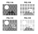
- FIGS. 11A to 11D are diagrams illustrating images obtained as a result of the multiple shooting.
- FIGS. 12A to 12C are diagrams illustrating images obtained as a result of the multiple shooting.
- FIG. 13 is a diagram illustrating pixels output as a result of magnitude comparison for each pixel.
- Image data RAW 1 ( 501 ) which is captured in first shooting by a digital camera is subjected to white balance processing 1 in a white balance processing unit 1 ( 502 ), and is once stored in a memory 1 ( 503 ).
- Negative gain acts on this image data processed in the white balance processing 1 , by a number of the multiple exposure, for use in combining images. In the present case, since the combination of two shootings is performed, gain of 1 ⁇ 2 acts on the image data ( 504 ).
- digitalized image data RAW 2 ( 511 ) obtained in second shooting is subjected to white balance processing in a white balance processing unit 2 ( 512 ).
- the processed image data RAW 2 ( 511 ) is once stored in a memory 2 ( 513 ) and then negative gain of 1 ⁇ 2 acts on the image in ( 514 ).
- the image data twice shot is subjected to addition processing in an addition unit ( 541 ) with respect to each pixel located at the same position of two screens.
- the combined images thus added is subjected to demosaic processing in a pre-filter ( 562 ).
- a pre-filter As an example, RAW image data obtained by an image sensor is taken up in which three color filters of RGB are arranged in a Bayer array as illustrated in FIG. 9A .
- the data arranged in the array illustrated in FIG. 9A is divided into three planes 9 B, 9 C, and 9 D of R pixel, G pixel, and B pixel respectively. Zero is inserted into pixels where no data is present. Then, each plane is tap-filtered in a horizontal and a vertical direction ( 562 ), and filled with zeros from FIG. 9B to FIG. 9E , from FIG. 9C to FIG. 9F , and from FIG. 9D to FIG. 9G .
- a filter with three taps may have low pass filter characteristics of “1-2-1”
- a filter with five taps may have low pass filter characteristics of “1-4-6-4-1”.
- Matrix conversion processing ( 563 ) is performed on the thus obtained image data of RGB three planes, in which RabGabBab is matrix-converted into image data of one screen of a luminance signal Y ab, a color difference signal Cr ab and a color difference signal Cb ab as shown in FIGS. 10A, 10B, and 10C , for each pixel in FIG. 9E , FIG. 9F , and FIG. 9G .
- a case where a third shooting result is further multiplexed on the multiple images in the first and second shooting will be described below with reference to a separated part of a block diagram shown under a dashed line. Since hardware devices used in this case has common components with the hardware used in the multiple addition processing in the first and second shooting, in describing the lower part under the dashed line, common reference numerals is used for the memory and the image processing such as the addition processing and the development processing.
- output data in which the first RAW data is added ( 541 ) to the second RAW data is accumulated in the memory 1 ( 503 ) in advance.
- a third captured image RAW 3 ( 531 ) is subjected to white balance processing in a white balance processing unit 3 ( 532 ) and once stored in a memory 2 .
- the demosaic processing and filter processing are performed on the image data arrayed in FIG. 9A , in the pre-filter ( 562 ) similar to the development processing of the first and second addition results.
- the matrix conversion processing ( 563 ) and the development processing ( 564 ) are carried out and then final data of the multiple addition image for the three shootings is recorded in the recording medium.
- the images are averagely multiplied by a negative gain for a number of multiplexed images, so that the multiple shooting of an automatic exposure correction type can be carried out, in which the combined images are hard to be saturated or to fail.
- each image is divided into a region including a plurality of pixels, and based on an average value of R, G, and B pixels, brightness (Br), saturation (S), and hue (H) are acquired.
- the acquired Br, S, and H are compared between regions located at the same position, and a pixel in a region showing a larger value between them remains.
- An image of an entire screen obtained by this substitution are processed and output, which is a point of the present exemplary embodiment.
- FIG. 1 is a block diagram illustrating a flow of image processing according to the first exemplary embodiment of the present invention.
- FIG. 6 is a flowchart illustrating the processing in FIG. 1 .
- FIG. 4 is a configuration diagram illustrating image processing in a digital camera as an example of an image capturing apparatus provided with a multiple shooting function.
- the image sensor ( 401 ) captures an image of the subject according to a shooting instruction.
- An output analog signal which is photoelectrically converted by the image sensor ( 401 ), is converted to digital image data ( 420 ) (hereinafter referred to as RAW data) in an AD conversion unit ( 402 ).
- the image sensor ( 401 ) includes color filters for a plurality of color components of R (red), G (green), and B (blue) as illustrated in FIG. 9A , and pixels which receive respective bands of light beam.
- the pixels are arranged in the Bayer array and the RAW data ( 420 ) includes image data of R, G, and B.
- a numerical number attached to RGB in FIGS. 9A to 9G indicates a location of RGB in a matrix. For example, R 24 indicates an R pixel located at a third row and a fifth column.
- the RAW data ( 420 ) is subjected to white balance processing in the white balance (WB) processing unit ( 403 ).
- a white balance controlling value for carrying out white balance is supplied from a central processing unit ( 404 ) (CPU).
- the CPU ( 404 ) analyzes the RAW data to calculate a most appropriate white balance value.
- the CPU ( 404 ) previously prepares a table of a white balance controlling value that is the most appropriate for colors of various light sources, in a random access memory (RAM) (not illustrated) in order to select and supply a table designated by a user.
- the user can freely switch to automatic white balances or pre-set white balance appropriate for each light source, and output the white balance controlling value.
- the RAW data subjected to the white balance processing is once stored in the memory ( 405 ). Regions for storing the RAW data in a plurality of shootings are kept in the memory ( 405 ) and the image data is written in a different region for each shooting.
- the memory ( 405 ) is controlled by a memory control unit ( 406 ).
- the memory control unit ( 406 ) can perform control to indicate “image data in what times of shooting” or “a position (an address) of a pixel within a screen” when the data is written in or read out from the memory ( 405 ).
- the next comparison processing unit ( 407 ) reads out from the memory ( 405 ) a pixel from each of a plurality of screens referring to position information (an address) specified by the memory control unit ( 406 ) to determine their magnitude relation.
- the comparison result output from the comparison processing unit ( 407 ) shows an address of the selected screen to indicate a screen and a pixel which have been selected as a result of the magnitude relation comparison.
- a pixel of one screen is read out according to an address indicated by the comparison result input to the memory control ( 406 ).
- the read out image data including pixels of one screen is transmitted to a low pass filter (LPF) processing unit ( 161 ), and smoothing processing is carried out on a boundary between the read out screens as described below.
- LPF low pass filter
- the image data subjected to the LPF processing is transmitted to the pre-filter processing unit ( 162 ), where the image data arranged in the Bayer array including RGB pixels as illustrated in FIG. 9 is divided into three virtual plan views, FIG. 9B , FIG. 9C , and FIG. 9D , constituted by R pixels, G pixels, and B pixels. The location where no pixel is present in each plane is filled in with zero.
- Each plane is tap-filtered in a horizontal and a vertical direction, and the planes are interpolated with zero as shown from FIG. 9B to FIG. 9E , from FIG. 9C to FIG. 9F , and from FIG. 9D to FIG. 9G .
- a filter with three taps may have low pass filter characteristics of “1-2-1”, and a filter with five taps may have low pass filter characteristics of “1-4-6-4-1”.
- the matrix conversion processing is performed on the RGB image data of three planes thus obtained by the pre-filter processing unit ( 462 ), in the matrix conversion processing unit ( 463 ).
- the matrix conversion processing is performed on each pixel located at the same position in FIGS. 9E, 9F, and 9G , from Rab-Gab-Bab into image data of a luminance signal Y ab—a color difference signal Cr ab—a color difference signal Cb ab as illustrated in FIGS. 10A, 10B, and 10C .
- various processing such as gamma correction, sharpness processing, and color conversion processing is performed on the three dimensional image data of YCrCb in a development processing unit ( 464 ).
- the image data is output as final image data and stored in a recording medium ( 465 ) as JPEG image data constituted by YCrCb.
- FIG. 6 With reference to each step of the flow chart in FIG. 6 , a method for multiplexing a plurality of images captured by the digital camera will be described based on the processing flow in FIG. 1 , which is a point of the present invention.
- firstly captured RAW data is RAW 1 ( 101 )
- secondly captured RAW data is RAW 2 ( 111 )
- thirdly captured RAW data is RAW 3 ( 131 ).
- the firstly captured RAW 1 ( 101 ) and the secondly captured RAW 2 ( 111 ) are subjected in the WB processing unit ( 403 ) to white balance processing 1 ( 102 ) in step 603 and in step 606 , respectively.
- a user may vary the controlling value to be different for each shooting.
- the RAW 1 and RAW 2 subjected to the white balance processing are once stored in the spatial memory 1 ( 103 ) and spatial memory 2 ( 113 ) in step 604 and in step 607 , respectively.
- the spatial memory 1 ( 103 ) and spatial memory 2 ( 113 ) are kept within a memory ( 405 ).
- the image data readout from the memories is branched into image data ( 104 and 114 ) and image data ( 105 and 115 ).
- the image data ( 104 and 114 ) is used to determine brightness of a pixel when the image is multiplexed.
- the image data ( 105 and 115 ) is used when the subject image is subjected to the multiplexing processing to obtain a final image.
- step 608 region dividing processing ( 141 and 144 ) is performed on the image data ( 104 and 114 ) for determining light and dark, respectively.
- the image data is divided into equally sized block regions within a screen.
- the screen is segmented such that one block includes 16 pixels (4 pixels (longitudinal) ⁇ 4 pixels (horizontal)) as a unit.
- 4 pixels (R), 8 pixels (G), and 4 pixels (B) constitute one block.
- step 609 average value calculation ( 142 and 145 ) is performed on each block obtained by the region dividing.
- average value calculation ( 142 and 145 ) average values of R, G, and B are calculated for each color component.
- weighted average may be carried out for the purpose of, for example, changing a contributing ratio of R, G, and B as necessary.
- FIG. 9A shows a location at an upper left end of one screen.
- R ave00 ( R 00+ R 02+ R 20+ R 22)/4 (1)
- G ave00 ( G 01+ G 03+ G 10+ G 12+ G 21+ G 23+ G 30+ G 32)/8 (2)
- B ave00 ( B 11+ B 13+ B 31+ B 33)/4 (3)
- brightness comparison processing ( 147 ) is performed which compares blocks located at the same position in the first screen and the second screen. If the brightness is not at the same level (No in step 611 ), the processing advances to step 612 . If the brightness of the block (00) read from the memory 1 ( 103 ) for the first shooting is greater than the brightness of the block (00) read from the memory 2 ( 113 ) for the second shooting (Yes in step 612 ), the processing advances to step 613 . In step 613 , each address of the pixels within the block (00), and the information in the first shooting synchronized with the address, are output as a comparison result ( 150 ).
- step 614 each address of the pixels within the block (00), and the information in the second shooting synchronized with the address, are output as a comparison result ( 150 ).
- step 615 saturation comparison processing ( 148 ) is performed, in which saturation comparison is performed between the blocks.
- step 615 If the saturation is not at the same level as a result of the comparison (No in step 615 ), the processing advances to step 616 . If the saturation of the block (00) read from the memory 1 ( 103 ) for the first shooting is greater than the saturation of the block (00) read from the memory 2 ( 113 ) for the second shooting (Yes in step 616 ), the processing advances to step 617 . In step 617 , each address of the pixels within the block (00), and the information in the first shooting synchronized with the address, are output as a comparison result ( 150 ).
- step 618 each address of the pixels within the block (00), and the information in the second shooting synchronized with the address, are output as a comparison result ( 150 ).
- step 615 If the saturation of the block (00) read from the memory 1 ( 103 ) for the first shooting is equal to the saturation of the block (00) read from the memory 2 ( 113 ) for the second shooting (Yes in step 615 ), the processing advances to step 619 .
- step 619 hue comparison processing is performed, in which hue comparison processing ( 149 ) is performed between the blocks located at the same position.
- step 620 each address of the pixels within the block (00), and the information in the first shooting synchronized with the address, are output as a comparison result ( 150 ).
- step 621 each address of the pixels within the block (00), and the information in the second shooting synchronized with the address, are output as a comparison result ( 150 ).
- step 622 information combining the thus obtained address of each pixel with the information in the first or second shooting is subjected to address management ( 140 ) in a memory control unit ( 406 ).
- a memory control unit ( 406 ) reads out the image data of one screen from the memory for each pixel, in the address management processing ( 140 ). At this time, if the information synchronized with the read pixel indicates the first shooting, the pixel data from the memory 1 ( 103 ) is output from a memory unit ( 405 ) in step 624 . If the information synchronized with the read pixel indicates the second shooting, the pixel is switched over and the pixel data from the memory 2 ( 113 ) is output from the memory unit ( 405 ) in step 624 .
- the processing unit same as the one used for the first and second shooting is used as a processing unit in the camera.
- FIG. 1 illustrating a processing flow
- the multiplexing processing for the third shooting and thereafter is segmented by a dashed line ( 180 ) separating a lower part which shows a flow same as a portion of an upper part of the diagram.
- step 630 the multiplexed image data for the first and second shooting output from the memory unit ( 405 ) is stored in the memory 1 ( 103 ) again.
- step 632 the image data RAW 3 ( 131 ) obtained when the third shooting is carried out, is subjected to the WB processing 3 ( 132 ) using a WB controlling value in a WB processing unit ( 403 ) similar to the first and second processing.
- step 633 the image data of the third shooting is stored in the memory 2 ( 113 ).
- the image data in the memory 1 ( 103 ) and the memory 2 ( 113 ) is subjected to the multiplexing processing which is similar to the one for the first and second shooting (step 608 to step 624 ).
- step 629 it is determined whether next shooting is to be carried out. If it is determined that shooting is to be ended, the processing advances to step 630 .
- step 630 the multiple image data output from the memory 1 ( 103 ) and the memory 2 ( 113 ) which is switched over by a switch (SW) ( 151 ) for each pixel, is transmitted to an LPF processing unit ( 461 ) and subjected to LPF processing.
- SW switch
- the LPF performs processing for making less visible a boundary of adjacent blocks between the first and second shooting.
- the pixel data in the Bayer array illustrated in FIG. 9A is developed into RGB planes shown in FIGS. 9B, 9C, and 9D .
- the filter of LPF characteristics may be applied both horizontally and vertically between the same pixel data of RGB using a 5-tap filter of (1-4-6-4-1) and the like.
- step 631 adaptive interpolation processing ( 162 ) is carried out in a pre-filter 2 processing unit ( 462 ) to obtain RGB values of each pixel in FIGS. 9E, 9F, and 9G to make less visible the boundary of adjacent blocks between the first and second shooting.
- a pixel value of G 33 in FIG. 9F is to be obtained, the following formulae that find out a difference between the pixels in a longitudinal and a lateral direction, are employed.
- Y ⁇ R 13+2 ⁇ R 33 ⁇ R 53
- X ⁇ R 31+2 ⁇ R 33 ⁇ R 35
- G 33 ( G 23+ G 43)/2( X>Y ) (6)
- G 33 ( G 32+ G 34)/2( X ⁇ Y ) (7)
- the multiple image data including three planes of RGB smoothed through the pre-filter 2 processing is transmitted to a matrix 2 conversion processing unit ( 463 ).
- a matrix 2 conversion processing unit 463 .
- RabGabBab for each pixel in FIGS. 9E, 9F, and 9G is matrix-converted to image data of YabCrabCbab as shown in FIGS. 10A, 10B, and 10C .
- a conversion coefficient in the matrix 2 conversion processing ( 163 ) may be different from the conversion coefficient in the matrix 1 conversion processing ( 163 ) in a comparison processing unit ( 143 and 146 ). Any coefficient can be used if an image quality obtained as a result of development processing is acceptable.
- step 633 the development processing ( 164 ) including gamma processing, sharpness processing, or color conversion processing is performed on the YCrCb data in a development processing unit ( 464 ).
- step 644 the image data subjected to the development processing is output as final combined data, which is stored ( 165 ) in a recording medium by a recording medium recording unit ( 465 ).
- each screen is divided into regions and an average value of the same color is obtained.
- the average value is subjected to the matrix conversion and the data located at the same position is compared with each other. According to the comparison result, it is determined which pixel of the captured image is to be selected as the image data.
- a plurality of images subjected to the multiple shooting can be multiplexed as shown in FIG. 11D without intermingling with each other, instead of FIG. 11C .
- a screen is divided into regions to calculate an average value for each region constituted by a plurality of pixels (M pixels ⁇ N pixels).
- M pixels ⁇ N pixels a region of M pixels ⁇ N pixels may be set centering around the target pixel to calculate an average value of adjacent pixels of the same color within the region.
- R 22 is presumed to be the target pixel in FIG. 9A .
- An average value is calculated centering around the pixel R 22 among pixels of the same color within a region of 5 pixels ⁇ 3 pixels.
- R ave ( R 22) ( R 20+ R 22+ R 24)/3 (9)
- G ave ( R 22) ( G 10+ G 12+ G 14+ G 21+ G 23+ G 30+ G 32+ G 34)/8 (10)
- B ave ( R 22) ( B 11+ B 13+ B 31+ B 33)/4 (11)
- step 610 average values (i.e., Rave(R), Gave(R), and Bave(R)) calculated through the above formulae are matrix-converted into elements of Br, S, and H as shown in FIGS. 10D, 10E, and 10F ( 143 and 146 ).
- a comparison is made in order of (01), (02), (03), . . . pixel by pixel in priority order of brightness, saturation, and hue to determine a pixel which has a greater value between pixels located at the same position.
- the LPF processing ( 161 ) in step 630 for smoothing the boundary between the blocks may be omitted.
- two screens are compared to select an image showing a larger BrSH value and to output the multiple image.
- an image having a smaller BrSH value can be selected in priority order of Br, S, and H to prioritize and overlay a darker image (or a light-colored image or an image of a smaller hue value).
- darker pixels as illustrated in FIG. 12C can be selected from captured images in FIGS. 12A and 12B and a multiplexed result can be output.
- This processing is effective when images of persons are captured in an overlaying manner against a background of a snow scene like a ski site.
- the comparison is made block by block in priority order of brightness, saturation, and hue, and output of a pixel is determined on the basis of the comparison result.
- the comparison does not necessarily have to be made with respect to all of brightness, saturation, and hue, but the comparison may be made on the basis of any one of them.
- the priority order may be changed according to a shooting mode, a shooting condition, and an image analyzing result etc., or the comparison about brightness, saturation, and hue may be selectively made.
- a digital camera provided with a multiple shooting function according to the second exemplary embodiment of the present invention will be described.
- the second exemplary embodiment as a minimum region unit of a block region division unit constituted by a plurality of pixels according to the first exemplary embodiment, one pixel is taken as one block region unit to compare the first shooting and the second shooting.
- FIG. 2 illustrates a block diagram illustrating a flow of each processing
- FIG. 7 illustrates a flow chart corresponding to the block diagram.
- Procedures until the image data RAW 1 ( 101 ) in the first shooting and RAW 2 ( 111 ) in the second shooting are subjected to the WB 1 processing ( 102 ) and the WB 2 processing ( 112 ) and written in the memory 1 ( 103 ) and the memory 2 ( 113 ) regions of the memory ( 405 ) respectively, are similar to the first exemplary embodiment.
- a comparison is made in order of (01), (02), (03), . . . from a pixel position (00) at an upper left end of the screen, pixel by pixel.
- the comparison processing unit ( 407 ) adjacent pixels in a horizontal and a vertical direction are transmitted at the same time, and are tap-filtered in a horizontal and vertical direction through pre-filter processing 1 ( 241 and 244 ) in step 709 .
- planes of RGB are filled in with zero as illustrated in FIG. 9B , FIG. 9C , and FIG. 9D to perform development into three planes.
- pixel interpolation including direction determination for checking continuity of a pixel in a horizontal and a vertical direction is performed.
- G 33 ( G 23+ G 43)/2( X>Y ) (14)
- G 33 ( G 32+ G 34)/2( X ⁇ Y ) (15)
- step 610 the multiple image data of RGB smoothed through the pre-filter 1 processing ( 241 and 244 ) is matrix-converted from RGB in FIGS. 9E, 9F, and 9G to BrSH data in FIGS. 10D, 10E, and 10F , similar to the first exemplary embodiment.
- the BrSH results in the first shooting and the second shooting are compared similar to the first exemplary embodiment.
- the comparison processing is made in order of (01), (02), (03), . . . pixel by pixel in priority order of brightness, saturation, and hue to determine a pixel showing a greater value among pixels located at the same position. Thus, it is determined whether the pixel in the first shooting or in the second shooting at that position is to be output.
- image processing of one screen is performed on the basis of the selected pixels, and as a result of multiple exposure, the processed screen is recorded on a recording medium. Processing in the third shooting and thereafter is also performed pursuant to the first exemplary embodiment.
- continuity of the image is determined in a horizontal and a vertical direction through the pre-filter 1 processing ( 241 and 244 ). Since comparison and determination are carried out pixel by pixel, the LPF processing ( 161 ) described in the first exemplary embodiment can be omitted.
- each coefficient defining the characteristics of the pre-filter 1 processing ( 241 and 244 ) may be different from a coefficient for the pre-filter 2 processing ( 162 ) in the image processing for outputting the final multiplexed result.
- the pre-filter 1 processing ( 241 and 244 ) may have a tap coefficient achieving a more greater LPF effect (e.g., an enlarged tap number) compared with the pre-filter 2 processing ( 162 ) in the image processing for final output.
- the image data which is captured multiple times is developed into brightness Br, saturation S, and hue H, at the same position for each pixel of each screen.
- the comparison result of the developed image data it is determined which pixel of captured image is to be selected as the image data.
- the hardware configuration according to the second exemplary embodiment is simplified as much as possible to speedup its processing.
- a digital camera provided with a multiple shooting function according to the third exemplary embodiment will be described as follows.
- the third exemplary embodiment is similar to the second exemplary embodiment in that one pixel is dealt with as a unit of one block region, and first and second shootings are compared.
- the third exemplary embodiment is different in that when making the comparison, peripheral pixels are not referenced and levels are compared only with respect to pixels at a target position.
- FIG. 3 A configuration of each processing unit within the digital camera is similar to FIG. 4 described with respect to the first exemplary embodiment.
- a block diagram that shows flow of each processing is illustrated in FIG. 3 and a flow chart corresponding to the block diagram is illustrated in FIG. 8 .
- RAW ( 101 ) and RAW ( 111 ) are subjected to WB 1 processing ( 102 ) and WB 2 processing ( 112 ) and are written in the memory 1 ( 103 ) and the memory 2 ( 113 ) regions of the memory ( 405 ) respectively, are similar to the first and second exemplary embodiments (steps 601 to 607 ).
- image data is transmitted from the memory 1 ( 103 ) and the memory 2 ( 113 ) to a comparison processing unit ( 407 ).
- the image data is transmitted pixel by pixel, from a pixel position (00) at an upper left end of the screen of FIG. 9A in order of (01), (02), (03), . . . .
- the comparison processing unit ( 407 ) the pixel data ( 104 ) in the first shooting and the pixel data in the second shooting at the same position is subjected to the comparison processing ( 347 ) with respect a magnitude level of the pixels, in steps 612 and 614 .
- step 622 according to a result of the comparison ( 150 ), it is determined whether to adopt a pixel in the first shooting or in the second shooting.
- a red part of the subject in the first shooting and a blue part of the subject in the second shooting may can be located at the same position.
- both colors may intermingle with each other. More specifically, with respect to an R pixel, R 1 in the first shooting>R 2 in the second shooting, while with respect to a B pixel, B 1 in the first shooting ⁇ B 2 in the second shooting. Therefore, the R 1 pixel in the first shooting and the B 2 pixel in the second shooting are developed in combination, so that the colors may become intermingled with each other.
- substantially simplified processing can be realized as compared to the first and second exemplary embodiments. Further, a processing speed can be much faster. Accordingly, also according to the third exemplary embodiment, the multiple shooting can be implemented by comparing image brightness and overlaying the images.
- aspects of the present invention can also be realized by a computer of a system or apparatus (or devices such as a CPU or MPU) that reads out and executes a program recorded on a memory device to perform the functions of the above-described embodiment(s), and by a method, the steps of which are performed by a computer of a system or apparatus by, for example, reading out and executing a program recorded on a memory device to perform the functions of the above-described embodiment(s).
- the program is provided to the computer for example via a network or from a recording medium of various types serving as the memory device (e.g., computer-readable medium).
Landscapes
- Engineering & Computer Science (AREA)
- Multimedia (AREA)
- Signal Processing (AREA)
- Physics & Mathematics (AREA)
- Spectroscopy & Molecular Physics (AREA)
- Color Television Image Signal Generators (AREA)
- Image Processing (AREA)
- Studio Devices (AREA)
Abstract
Description
Rave00=(R00+R02+R20+R22)/4 (1)
Gave00=(G01+G03+G10+G12+G21+G23+G30+G32)/8 (2)
Bave00=(B11+B13+B31+B33)/4 (3)
Y=−
X=−
G33=(G23+G43)/2(X>Y) (6)
G33=(G32+G34)/2(X<Y) (7)
G33=(G23+G43+G32+G34)/4(X=Y) (8)
Rave (R22)=(R20+R22+R24)/3 (9)
Gave (R22)=(G10+G12+G14+G21+G23+G30+G32+G34)/8 (10)
Bave (R22)=(B11+B13+B31+B33)/4 (11)
Y=|−
X=|−
G33=(G23+G43)/2(X>Y) (14)
G33=(G32+G34)/2(X<Y) (15)
G33=(G23+G43+G32+G34)/4(X=Y) (16)
Claims (15)
Applications Claiming Priority (2)
| Application Number | Priority Date | Filing Date | Title |
|---|---|---|---|
| JP2012-025286 | 2012-02-08 | ||
| JP2012025286A JP5990004B2 (en) | 2012-02-08 | 2012-02-08 | Imaging device |
Publications (2)
| Publication Number | Publication Date |
|---|---|
| US20130215288A1 US20130215288A1 (en) | 2013-08-22 |
| US9414035B2 true US9414035B2 (en) | 2016-08-09 |
Family
ID=48928090
Family Applications (1)
| Application Number | Title | Priority Date | Filing Date |
|---|---|---|---|
| US13/760,857 Active US9414035B2 (en) | 2012-02-08 | 2013-02-06 | Image capturing apparatus provided with a function of combining a plurality of captured images |
Country Status (5)
| Country | Link |
|---|---|
| US (1) | US9414035B2 (en) |
| JP (1) | JP5990004B2 (en) |
| KR (1) | KR101581896B1 (en) |
| CN (1) | CN103248902A (en) |
| TW (1) | TW201334506A (en) |
Families Citing this family (7)
| Publication number | Priority date | Publication date | Assignee | Title |
|---|---|---|---|---|
| JP5979961B2 (en) * | 2012-05-07 | 2016-08-31 | キヤノン株式会社 | FOCUS DETECTION DEVICE, FOCUS DETECTION METHOD, AND IMAGING DEVICE |
| US9741117B2 (en) * | 2014-12-22 | 2017-08-22 | Motorola Mobility Llc | Multiple camera apparatus and method for synchronized auto white balance |
| CN105491358B (en) * | 2015-11-26 | 2018-11-16 | 努比亚技术有限公司 | A kind of image processing method and device, terminal |
| EP3393117A4 (en) * | 2015-12-15 | 2018-11-14 | Ricoh Company, Ltd. | Image-processing device and image-processing method |
| CN105827965B (en) * | 2016-03-25 | 2019-04-12 | 维沃移动通信有限公司 | A kind of image processing method and mobile terminal based on mobile terminal |
| KR102087500B1 (en) * | 2018-05-17 | 2020-03-10 | 주식회사 이오씨 | Apparatus and method of processing orthogonal composition thermogram image |
| CN111953955B (en) * | 2020-08-26 | 2022-01-04 | 维沃移动通信有限公司 | White balance compensation method and device and electronic equipment |
Citations (13)
| Publication number | Priority date | Publication date | Assignee | Title |
|---|---|---|---|---|
| JPH11225308A (en) | 1998-02-06 | 1999-08-17 | Nec Corp | Multiple image pickup device for digital camera |
| US20020054220A1 (en) | 2000-10-19 | 2002-05-09 | Yoshitaka Takeuchi | Image pickup apparatus |
| JP2002223452A (en) | 2001-01-26 | 2002-08-09 | Asahi Optical Co Ltd | Image interpolation device |
| JP2003319404A (en) | 2002-04-22 | 2003-11-07 | Olympus Optical Co Ltd | Imaging apparatus, method therefor, and program therefor |
| JP2004297407A (en) | 2003-03-26 | 2004-10-21 | Fuji Photo Film Co Ltd | Picture processing method |
| JP2006128740A (en) | 2004-10-26 | 2006-05-18 | Nikon Corp | Digital camera |
| US20070013777A1 (en) * | 2005-07-15 | 2007-01-18 | Sony Corporation | Imaging device and imaging method |
| CN101116325A (en) | 2005-02-07 | 2008-01-30 | 松下电器产业株式会社 | Imaging device |
| US20080055683A1 (en) * | 2006-09-06 | 2008-03-06 | Samsung Electronics Co., Ltd. | Image generation system, method and medium |
| US20080084880A1 (en) | 2006-10-10 | 2008-04-10 | Pranav Dharwadkar | Two-level load-balancing of network traffic over an MPLS network |
| US20090021594A1 (en) * | 2004-10-26 | 2009-01-22 | Nikon Corporation | Digital Camera and Image Combination Device |
| CN101426090A (en) | 2007-10-31 | 2009-05-06 | 欧姆龙株式会社 | Image processing apparatus |
| CN101661154A (en) | 2008-08-26 | 2010-03-03 | 韩国外国语大学校研究产学协力团 | digital presenter |
Family Cites Families (3)
| Publication number | Priority date | Publication date | Assignee | Title |
|---|---|---|---|---|
| JP3619077B2 (en) | 1999-09-20 | 2005-02-09 | キヤノン株式会社 | IMAGING DEVICE, IMAGING DEVICE CONTROL METHOD, AND STORAGE MEDIUM |
| JP2001223913A (en) | 1999-11-30 | 2001-08-17 | Matsushita Electric Ind Co Ltd | Image processor, image processing method and recording medium |
| JP4777675B2 (en) | 2005-03-17 | 2011-09-21 | 株式会社リコー | Image processing apparatus, image display apparatus, image processing method, program for causing computer to execute the method, and recording medium |
-
2012
- 2012-02-08 JP JP2012025286A patent/JP5990004B2/en not_active Expired - Fee Related
-
2013
- 2013-02-04 TW TW102104202A patent/TW201334506A/en unknown
- 2013-02-06 US US13/760,857 patent/US9414035B2/en active Active
- 2013-02-07 CN CN2013100494473A patent/CN103248902A/en active Pending
- 2013-02-08 KR KR1020130014317A patent/KR101581896B1/en active IP Right Grant
Patent Citations (16)
| Publication number | Priority date | Publication date | Assignee | Title |
|---|---|---|---|---|
| JPH11225308A (en) | 1998-02-06 | 1999-08-17 | Nec Corp | Multiple image pickup device for digital camera |
| US20020054220A1 (en) | 2000-10-19 | 2002-05-09 | Yoshitaka Takeuchi | Image pickup apparatus |
| JP2002223452A (en) | 2001-01-26 | 2002-08-09 | Asahi Optical Co Ltd | Image interpolation device |
| JP2003319404A (en) | 2002-04-22 | 2003-11-07 | Olympus Optical Co Ltd | Imaging apparatus, method therefor, and program therefor |
| JP2004297407A (en) | 2003-03-26 | 2004-10-21 | Fuji Photo Film Co Ltd | Picture processing method |
| US20090021594A1 (en) * | 2004-10-26 | 2009-01-22 | Nikon Corporation | Digital Camera and Image Combination Device |
| JP2006128740A (en) | 2004-10-26 | 2006-05-18 | Nikon Corp | Digital camera |
| CN101116325A (en) | 2005-02-07 | 2008-01-30 | 松下电器产业株式会社 | Imaging device |
| CN100539645C (en) | 2005-02-07 | 2009-09-09 | 松下电器产业株式会社 | Imaging device |
| US20070013777A1 (en) * | 2005-07-15 | 2007-01-18 | Sony Corporation | Imaging device and imaging method |
| CN1917611A (en) | 2005-07-15 | 2007-02-21 | 索尼株式会社 | Imaging device and imaging method |
| US20080055683A1 (en) * | 2006-09-06 | 2008-03-06 | Samsung Electronics Co., Ltd. | Image generation system, method and medium |
| CN101141571A (en) | 2006-09-06 | 2008-03-12 | 三星电子株式会社 | Image generation system, method and medium |
| US20080084880A1 (en) | 2006-10-10 | 2008-04-10 | Pranav Dharwadkar | Two-level load-balancing of network traffic over an MPLS network |
| CN101426090A (en) | 2007-10-31 | 2009-05-06 | 欧姆龙株式会社 | Image processing apparatus |
| CN101661154A (en) | 2008-08-26 | 2010-03-03 | 韩国外国语大学校研究产学协力团 | digital presenter |
Also Published As
| Publication number | Publication date |
|---|---|
| JP5990004B2 (en) | 2016-09-07 |
| KR101581896B1 (en) | 2015-12-31 |
| TW201334506A (en) | 2013-08-16 |
| US20130215288A1 (en) | 2013-08-22 |
| JP2013162479A (en) | 2013-08-19 |
| CN103248902A (en) | 2013-08-14 |
| KR20130091691A (en) | 2013-08-19 |
Similar Documents
| Publication | Publication Date | Title |
|---|---|---|
| US9414035B2 (en) | Image capturing apparatus provided with a function of combining a plurality of captured images | |
| US10916036B2 (en) | Method and system of generating multi-exposure camera statistics for image processing | |
| US7973827B2 (en) | Image data generating apparatus, method and program for generating an image having high spatial and high temporal resolution | |
| JP5713752B2 (en) | Image processing apparatus and control method thereof | |
| US9858644B2 (en) | Bayer color filter array based high dynamic range video recording method and device | |
| US8401341B2 (en) | Image processing apparatus, method, and storage medium for generating a magnified image by synthesizing structure and texture | |
| JP6420540B2 (en) | Image processing apparatus, control method therefor, program, and storage medium | |
| JP2005142680A (en) | Image processing apparatus | |
| JP2009124598A (en) | Image processor, and image processing method | |
| EP3439282A1 (en) | Image pickup device, image processing device, and electronic apparatus | |
| JPWO2008150017A1 (en) | Signal processing method and signal processing apparatus | |
| JP2016208306A (en) | Image processing device, imaging system having the same and image processing method | |
| JP5984975B2 (en) | Imaging apparatus, imaging method, and program | |
| CN104243804A (en) | Imaging apparatus, image processing apparatus, and control method therefor | |
| JP2018186514A (en) | Image processing device, imaging system having the same and image processing method | |
| JP2022115944A (en) | Imaging apparatus | |
| US20180365802A1 (en) | Image processing apparatus, image processing method, and non-transitory computer-readable recording medium | |
| JPH07131718A (en) | Picture synthesizer | |
| KR20120022642A (en) | Image processing apparatus and method for controlling image processing apparatus | |
| JP6786273B2 (en) | Image processing equipment, image processing methods, and programs | |
| JP2008219230A (en) | Imaging apparatus, and image processing method | |
| JP3951993B2 (en) | IMAGING DEVICE AND COLOR DATA MEASURING METHOD USED FOR THIS IMAGING DEVICE | |
| JP5952573B2 (en) | Image processing apparatus and control method thereof | |
| US20240114251A1 (en) | Server device and program | |
| JP5676972B2 (en) | Image processing apparatus, image processing method, image processing program, and storage medium |
Legal Events
| Date | Code | Title | Description |
|---|---|---|---|
| AS | Assignment |
Owner name: CANON KABUSHIKI KAISHA, JAPAN Free format text: ASSIGNMENT OF ASSIGNORS INTEREST;ASSIGNOR:TAKEUCHI, YOSHITAKA;REEL/FRAME:030399/0223 Effective date: 20130131 |
|
| STCF | Information on status: patent grant |
Free format text: PATENTED CASE |
|
| MAFP | Maintenance fee payment |
Free format text: PAYMENT OF MAINTENANCE FEE, 4TH YEAR, LARGE ENTITY (ORIGINAL EVENT CODE: M1551); ENTITY STATUS OF PATENT OWNER: LARGE ENTITY Year of fee payment: 4 |
|
| FEPP | Fee payment procedure |
Free format text: MAINTENANCE FEE REMINDER MAILED (ORIGINAL EVENT CODE: REM.); ENTITY STATUS OF PATENT OWNER: LARGE ENTITY |