US9403632B1 - Fluid dispenser - Google Patents
Fluid dispenser Download PDFInfo
- Publication number
- US9403632B1 US9403632B1 US13/919,981 US201313919981A US9403632B1 US 9403632 B1 US9403632 B1 US 9403632B1 US 201313919981 A US201313919981 A US 201313919981A US 9403632 B1 US9403632 B1 US 9403632B1
- Authority
- US
- United States
- Prior art keywords
- stem
- air
- housing
- interior chamber
- bag
- Prior art date
- Legal status (The legal status is an assumption and is not a legal conclusion. Google has not performed a legal analysis and makes no representation as to the accuracy of the status listed.)
- Active - Reinstated
Links
- 239000012530 fluid Substances 0.000 title claims abstract description 78
- 239000003381 stabilizer Substances 0.000 claims abstract description 29
- 238000010276 construction Methods 0.000 claims description 3
- 230000000087 stabilizing effect Effects 0.000 claims 1
- -1 but not limited to Substances 0.000 description 5
- 239000006210 lotion Substances 0.000 description 5
- 239000012855 volatile organic compound Substances 0.000 description 5
- 230000000844 anti-bacterial effect Effects 0.000 description 2
- 238000000605 extraction Methods 0.000 description 2
- 239000011521 glass Substances 0.000 description 2
- 239000007788 liquid Substances 0.000 description 2
- 239000000314 lubricant Substances 0.000 description 2
- 239000000463 material Substances 0.000 description 2
- 239000000203 mixture Substances 0.000 description 2
- 239000000344 soap Substances 0.000 description 2
- 239000000126 substance Substances 0.000 description 2
- 241000894006 Bacteria Species 0.000 description 1
- 241001134446 Niveas Species 0.000 description 1
- 239000000853 adhesive Substances 0.000 description 1
- 230000001070 adhesive effect Effects 0.000 description 1
- 239000008341 cosmetic lotion Substances 0.000 description 1
- 230000033001 locomotion Effects 0.000 description 1
- 239000010687 lubricating oil Substances 0.000 description 1
- 239000003960 organic solvent Substances 0.000 description 1
- 230000008520 organization Effects 0.000 description 1
- 230000003647 oxidation Effects 0.000 description 1
- 238000007254 oxidation reaction Methods 0.000 description 1
- 239000003973 paint Substances 0.000 description 1
- 230000002035 prolonged effect Effects 0.000 description 1
- 238000009877 rendering Methods 0.000 description 1
- 238000003466 welding Methods 0.000 description 1
Images


Classifications
-
- B—PERFORMING OPERATIONS; TRANSPORTING
- B05—SPRAYING OR ATOMISING IN GENERAL; APPLYING FLUENT MATERIALS TO SURFACES, IN GENERAL
- B05B—SPRAYING APPARATUS; ATOMISING APPARATUS; NOZZLES
- B05B15/00—Details of spraying plant or spraying apparatus not otherwise provided for; Accessories
- B05B15/30—Dip tubes
-
- B—PERFORMING OPERATIONS; TRANSPORTING
- B65—CONVEYING; PACKING; STORING; HANDLING THIN OR FILAMENTARY MATERIAL
- B65D—CONTAINERS FOR STORAGE OR TRANSPORT OF ARTICLES OR MATERIALS, e.g. BAGS, BARRELS, BOTTLES, BOXES, CANS, CARTONS, CRATES, DRUMS, JARS, TANKS, HOPPERS, FORWARDING CONTAINERS; ACCESSORIES, CLOSURES, OR FITTINGS THEREFOR; PACKAGING ELEMENTS; PACKAGES
- B65D81/00—Containers, packaging elements, or packages, for contents presenting particular transport or storage problems, or adapted to be used for non-packaging purposes after removal of contents
- B65D81/24—Adaptations for preventing deterioration or decay of contents; Applications to the container or packaging material of food preservatives, fungicides, pesticides or animal repellants
- B65D81/245—Internal membrane, floating cover or the like isolating the contents from the ambient atmosphere
-
- B—PERFORMING OPERATIONS; TRANSPORTING
- B05—SPRAYING OR ATOMISING IN GENERAL; APPLYING FLUENT MATERIALS TO SURFACES, IN GENERAL
- B05B—SPRAYING APPARATUS; ATOMISING APPARATUS; NOZZLES
- B05B11/00—Single-unit hand-held apparatus in which flow of contents is produced by the muscular force of the operator at the moment of use
- B05B11/0005—Components or details
- B05B11/0037—Containers
- B05B11/0039—Containers associated with means for compensating the pressure difference between the ambient pressure and the pressure inside the container, e.g. pressure relief means
- B05B11/0044—Containers associated with means for compensating the pressure difference between the ambient pressure and the pressure inside the container, e.g. pressure relief means compensating underpressure by ingress of atmospheric air into the container, i.e. with venting means
-
- B—PERFORMING OPERATIONS; TRANSPORTING
- B05—SPRAYING OR ATOMISING IN GENERAL; APPLYING FLUENT MATERIALS TO SURFACES, IN GENERAL
- B05B—SPRAYING APPARATUS; ATOMISING APPARATUS; NOZZLES
- B05B11/00—Single-unit hand-held apparatus in which flow of contents is produced by the muscular force of the operator at the moment of use
- B05B11/01—Single-unit hand-held apparatus in which flow of contents is produced by the muscular force of the operator at the moment of use characterised by the means producing the flow
- B05B11/02—Membranes or pistons acting on the contents inside the container, e.g. follower pistons
- B05B11/026—Membranes separating the content remaining in the container from the atmospheric air to compensate underpressure inside the container
-
- B—PERFORMING OPERATIONS; TRANSPORTING
- B05—SPRAYING OR ATOMISING IN GENERAL; APPLYING FLUENT MATERIALS TO SURFACES, IN GENERAL
- B05B—SPRAYING APPARATUS; ATOMISING APPARATUS; NOZZLES
- B05B11/00—Single-unit hand-held apparatus in which flow of contents is produced by the muscular force of the operator at the moment of use
- B05B11/01—Single-unit hand-held apparatus in which flow of contents is produced by the muscular force of the operator at the moment of use characterised by the means producing the flow
- B05B11/02—Membranes or pistons acting on the contents inside the container, e.g. follower pistons
- B05B11/028—Pistons separating the content remaining in the container from the atmospheric air to compensate underpressure inside the container
- B05B11/029—Pistons separating the content remaining in the container from the atmospheric air to compensate underpressure inside the container located on top of the remaining content
Definitions
- This invention relates to dispensers used for dispensing fluids such as, but not limited to, lotions such as skin lotions, and industrial fluids such as volatile organic compounds (VOCs) and lubricants.
- fluids such as, but not limited to, lotions such as skin lotions, and industrial fluids such as volatile organic compounds (VOCs) and lubricants.
- VOCs volatile organic compounds
- Fluids are often stored in vessels from which they are intermittently dispensed. Fluids include chemical compositions some of which are vulnerable to oxidation upon prolonged contact with air present in the environment. Some fluids are chemical compositions which include volatile organic components which have a tendency to evaporate or otherwise escape from containers in which they are stored and from which they are dispensed. There is a continual need for ways to reduce fluid exposure to air.
- Patent Application Number WO0240122A2 and U.S. Pat. No. 7,000,806 each disclose a dispenser for dispensing a fluid that includes a rigid vial with a main fluid chamber containing a fluid, and a pump assembly that is in fluid communication with the main fluid chamber and is configured to dispense a predetermined quantity of fluid from the main fluid chamber.
- a flexible bladder is provided which is located within the main fluid chamber and is configured to expand to fill the ullage created within the main fluid chamber during dispensing of fluid by the pump assembly.
- the resilient bladder tends to force itself outwardly toward the rigid vial and, in turn, increases the pressure within the main fluid chamber in comparison to the interior of the bladder to thereby prevent the ingress of air or vapors through the bladder or otherwise into the main fluid chamber.
- U.S. Pat. No. 4,817,830 discloses an improved thin-walled pressure vessel having a bladder therein.
- This vessel includes a shell having an opening and a spout disposed around the opening.
- An improved cap normally closes this opening, secures the bladder to the shell of the vessel, and provides communication between the outside of the vessel and the inside of the bladder.
- the cap member comprises a main body member having an opening which receives a valve member. This valve member extends out through one end of the cap member. It also extends through the opposite end of the cap and into the bladder through an opening in the bladder. The valve member engages a portion of the bladder around the opening and clamps this portion against the main body member to secure the bladder to the cap member. As the pressure in the bladder increases, it forces the valve member further against the walls of the opening in the main body member, increasing the clamping force to firmly secure the bladder to the cap member.
- a fluid dispenser for dispensing fluids such as, but not limited to, cosmetic lotions or industrial fluids such as, but not limited to, paint.
- the fluid dispenser of the invention comprises: a housing, a hand pump, at least one bag, and a stem stabilizer.
- the housing defines an interior chamber and a housing wall.
- the housing wall defines at least one air-vent hole for ingress of air.
- the hand pump has a stem which extends downward into the interior chamber of the housing.
- the at least one bag is located in the interior chamber and is sealed except for being connected to the at least one air-vent hole such that each air-bent hole has a bag connected to it and air is prevented from entering the interior chamber except for the air that enters the at least one air bag. Negative pressure is created in the interior chamber when fluid is extracted from the interior chamber via hand pump, this causes air to flow into the at least one air bag and thus the fluid inside the interior chamber is kept separate from the air entering the at least one air bag.
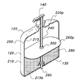
- FIG. 1 is a perspective view of a fluid dispenser, according to the present invention.
- FIG. 1A is a cross-section view of a fluid dispenser, according to the present invention.
- FIG. 2 is perspective front section view of a fluid dispenser having a single air bag, according to the present invention.
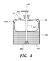
- FIG. 3 is a rear perspective view of the fluid dispenser shown in FIG. 2 .
- FIG. 4 is a cross-section view of a fluid dispenser, according to the present invention.
- FIG. 5 is a perspective view of a fluid dispenser, according to the present invention.
- FIG. 6 is perspective front section view of a fluid dispenser having two air bags, according to the present invention.
- FIG. 7 is front section view of a fluid dispenser having two air bags, according to the present invention.
- FIG. 8 is front section view of a fluid dispenser having two air bags, according to the present invention.
- FIG. 9 is a perspective view of a fluid dispenser, according to the present invention.
- FIG. 10 is a perspective view of an industrial fluid dispenser, according to the present invention.
- FIG. 11 is an enlarged section view of a fluid dispenser, according to the invention.
- FIG. 12 shows a table (Table 1) that lists reference numbers and their associated descriptions.
- This invention is directed to dispensers used for dispensing fluids such as, but not limited to, lotions such as skin lotions, and industrial fluids such as volatile organic compounds (VOCs) and lubricants.
- fluids such as, but not limited to, lotions such as skin lotions, and industrial fluids such as volatile organic compounds (VOCs) and lubricants.
- VOCs volatile organic compounds
- top”, “bottom”, “side”, “front”, “rear”, “upper”, “lower”, “vertical”, “horizontal”, “height”, “width”, “length” and the like are used herein merely to describe points of reference and do not limit the present invention to any specific orientation or configuration.
- the claimed apparatus and components may be of any size, shape or configuration suitable for operation of the apparatus and may be constructed of any suitable materials.
- the fluid dispenser of the invention is denoted generally by the numeric label “ 100 ”.
- the fluid dispenser 100 comprises a housing 120 , a hand pump 140 , and at least one bag 160 .
- the hand pump 140 can be any suitable hand pump such as, but not limited to, a hand pump used in NIVEA® “Original Moisture Daily Lotion” dispensers; also such as, but not limited to, a hand pump used in Softsoap® clean ProtectionTM “WASH AWAY BACTERIA” dispensers distributed by COLGATE-PALMOLIVE Company of New York, N.Y., USA.
- the housing 120 has a top end 125 , a base end 130 , an interior chamber 180 , and a housing wall 200 ; the housing wall 200 defines an outer wall surface 210 and an inner wall surface 215 .
- the housing wall 200 defines at least one air-vent hole 220 for ingress of air into the at least one bag 160 .
- the at least one air-vent hole 220 extends through the housing wall 200 between outer and inner housing wall surfaces 210 and 215 .
- the hand pump 140 includes a stem 240 ; the stem 240 defines an outer stem diameter 250 .
- the stem 240 is in communication with the interior chamber 180 ; for example, in FIG. 6 the stem 240 is shown extending downward into the interior chamber 180 of housing 100 .
- the housing 100 can be made of any suitable material such as, but not limited to, plastic.
- the plastic can be translucent, transparent or opaque.
- the housing 120 can be made of glass.
- the glass can be translucent, transparent or opaque. Indicia can be printed directly to the outer wall surface 210 of housing wall 200 ; decals can also be applied to the outer wall surface 210 of housing wall 200 .
- the hand pump 140 can also be made of plastic.
- the at least one bag 160 has an opening 170 which is aligned with the at least one air-vent hole 220 .
- the opening 170 can be in sealed engagement with the surrounding surface of the at least one air-vent hole 220 .
- the bag opening 170 can be affixed in air-tight engagement around the at least one air-vent hole 220 using a suitable adhesive 175 (see FIG. 11 ).
- the hand-pump 140 is in air-tight sealed engagement with respect to the top end 125 of the housing; this can be achieved by any suitable means such as ultra-sonic welding.
- the at least one bag 160 has sufficient volume capacity to ensure that the at least one bag 160 can hold a sufficient amount of air (received by the at least one air-vent hole 220 ) to ensure fluid 280 can be extracted easily by hand-pump 140 .
- a stem stabilizer 260 helps the stem 240 resist possible sideways pressure when the at least one air bag 160 fills with air and presses against the stem 240 .
- the stem stabilizer 260 can take any suitable form.
- the stem stabilizer 260 shown for example in FIG. 4 extends upward from the base end 130 of housing 100 .
- the stem stabilizer defines a circular member 262 which in turn defines through-hole 265 ; the through-hole 265 has a sufficient bore to accommodate the width of the stem 240 .
- the through-hole 265 of the stem stabilizer 260 secures the stem 240 such that the stem 240 can resist sideways forces that might otherwise cause the stem 240 to flex and hence effectively shorten its operating length inside the interior chamber 180 thereby rendering it harder to extract fluid 280 from the base end 130 via the stem 240 in response to a user (not shown) applying reciprocal motions to the hand pump 140 .
- the stem stabilizer can be of substantially planar construction with a through-hole 300 disposed therein; the through-hole 300 being of sufficient dimensions to allow the stem 240 to be secured by the through-hole 300 .
- FIG. 9 where the planar stem stabilizer is labeled 260 p .
- the stem stabilizer 260 p can be used alone.
- the stem stabilizer 260 p can be used in combination with the stem stabilizer 260 as shown in FIG. 9 .
- FIGS. 1A through 4 show how one non-limiting embodiment of the fluid dispenser 100 works; a user typically uses their hand (not shown) to apply pressure to the top of a hand pump 140 which forces fluid (such as, but not limited to, anti-bacterial liquid soap) to flow from the interior chamber 180 to the exterior of the fluid dispenser 100 via stem 240 .
- the forced fluid extraction from the interior chamber 180 causes negative pressure in chamber 180 which in turn causes air to enter the at least one bag 160 via at least one air-vent hole 220 .
- the stem stabilizer 260 has the circular member 262 with supporting legs for securing the circular member 262 to the housing 120 .
- FIGS. 6 through 8 show how one non-limiting embodiment of the fluid dispenser 100 works; a user typically uses their hand (not shown) to apply pressure to the top of a hand pump 140 which forces fluid (such as, but not limited to, anti-bacterial liquid soap) to flow from the interior chamber 180 to the exterior of the fluid dispenser 100 via stem 240 .
- the forced fluid extraction from the interior chamber 180 causes negative pressure in chamber 180 which in turn causes air to enter a plurality of air bags 160 p via at least one air-vent hole 220 .
- FIGS. 6 through 8 only two bags are shown (labeled as 160 p ) and the two air-vent holes are labeled 220 p .
- the stem stabilizer 260 ensures that the stem 240 remains in a vertical configuration as the air bags 160 p inflate.
- the invention is an industrial size fluid dispenser 100 i (see FIG. 10 ) made up of a housing 100 i , fluid dispensing line 140 i , and at least one industrial sized bag 160 pi .
- the at least one industrial sized bag 160 pi which upon full deployment has a volume capacity of the industrial size bag being at least 2 gallons; and preferably between 2 and 25 gallons.
- An industrial fluid 280 i such as, but not limited to, lubricating oil can be dispensed from the industrial size housing 120 i via fluid dispensing line 140 i .
- An industrial size fluid dispenser 100 i is defined herein as fluid dispenser having the capacity to dispense at least 5 gallons of fluid.
- the fluid capacity of the fluid dispenser 100 i can be between 5 gallons and 200 gallons of fluid.
- the housing 120 i could be a 50 gallon drum.
- Industrial fluids that can be dispensed by fluid dispenser 100 i include, but are not limited to, volatile organic solvents (VOCs).
- VOCs volatile organic solvents
Abstract
Description
Claims (6)
Priority Applications (1)
| Application Number | Priority Date | Filing Date | Title |
|---|---|---|---|
| US13/919,981 US9403632B1 (en) | 2013-06-17 | 2013-06-17 | Fluid dispenser |
Applications Claiming Priority (1)
| Application Number | Priority Date | Filing Date | Title |
|---|---|---|---|
| US13/919,981 US9403632B1 (en) | 2013-06-17 | 2013-06-17 | Fluid dispenser |
Publications (1)
| Publication Number | Publication Date |
|---|---|
| US9403632B1 true US9403632B1 (en) | 2016-08-02 |
Family
ID=56507190
Family Applications (1)
| Application Number | Title | Priority Date | Filing Date |
|---|---|---|---|
| US13/919,981 Active - Reinstated US9403632B1 (en) | 2013-06-17 | 2013-06-17 | Fluid dispenser |
Country Status (1)
| Country | Link |
|---|---|
| US (1) | US9403632B1 (en) |
Cited By (3)
| Publication number | Priority date | Publication date | Assignee | Title |
|---|---|---|---|---|
| US20190009973A1 (en) * | 2017-07-06 | 2019-01-10 | Provensis Limited | Canister Device for Producing Sclerosing Foam |
| USD842121S1 (en) * | 2017-09-29 | 2019-03-05 | Have&Be Co., Ltd | Cosmetic container |
| CN109649812A (en) * | 2018-12-20 | 2019-04-19 | 无锡飞天润滑油科技股份有限公司 | A kind of lubricating oil transport device |
Citations (81)
| Publication number | Priority date | Publication date | Assignee | Title |
|---|---|---|---|---|
| US987970A (en) * | 1910-08-29 | 1911-03-28 | John H Earl | Apparatus for dispensing beverages. |
| US1300183A (en) * | 1918-04-22 | 1919-04-08 | Luxe Brush Company De | Liquid-dispensing device. |
| US1427758A (en) * | 1920-10-12 | 1922-08-29 | Mclaughlin Frank | Device for feeding fluid, semifluid, and plastic substances |
| US1471091A (en) | 1922-03-27 | 1923-10-16 | Alfred N Bessesen | Fluid-pressure device |
| US1602354A (en) * | 1925-03-05 | 1926-10-05 | Fowler Charles | Separator |
| US1783419A (en) * | 1929-04-30 | 1930-12-02 | Fred W Fitch | Dispenser charge-regulating device |
| US1810135A (en) * | 1929-02-04 | 1931-06-16 | Fred W Fitch | Cream dispenser |
| US1854458A (en) * | 1931-04-06 | 1932-04-19 | Quincy Augusta M De | Powder spray |
| US1977360A (en) * | 1933-10-19 | 1934-10-16 | Frank A Talbot | Liquid dispensing container and pump |
| US1998752A (en) * | 1932-02-24 | 1935-04-23 | Lubrication Corp | Lubricating device |
| US1998751A (en) * | 1932-02-24 | 1935-04-23 | Lubrication Corp | Lubricating device |
| US2268592A (en) * | 1940-03-21 | 1942-01-06 | American Can Co | Dispensing container |
| US2286797A (en) * | 1940-06-21 | 1942-06-16 | Francisco M Duerme | Nursing bottle |
| US2673013A (en) * | 1949-12-27 | 1954-03-23 | Dwight H Hester | Device for dispensing predetermined amounts of liquid from containers |
| US2684182A (en) * | 1952-03-29 | 1954-07-20 | Pauline H Strauss | Cigarette lighter fuel filler |
| US2767417A (en) * | 1954-12-28 | 1956-10-23 | Nicholas C Amen | Dispenser and applicator for heavy lubricants |
| US2810496A (en) * | 1954-02-26 | 1957-10-22 | Russell J Gray | Lubricant dispensing apparatus and the like |
| US2861839A (en) * | 1957-01-14 | 1958-11-25 | Mellon Russell | Combination container, cap and sprayer |
| US2915225A (en) * | 1956-04-24 | 1959-12-01 | County Lab Ltd | Viscous fluid dispenser |
| US2999500A (en) * | 1954-05-22 | 1961-09-12 | Schurer Friedrich | Container for taking and storing of biological fluids |
| US3062415A (en) * | 1959-01-14 | 1962-11-06 | John W Anderson | Improved dispenser delivering chamber |
| US3072296A (en) * | 1958-12-31 | 1963-01-08 | Technicon Instr | Pumping apparatus |
| US3319837A (en) * | 1965-01-27 | 1967-05-16 | Air Ject Corp | Dispensing device |
| US3343701A (en) * | 1965-07-14 | 1967-09-26 | Frank D Mahoney | Sealing and exhausting device for containers |
| US3360168A (en) * | 1965-01-08 | 1967-12-26 | Bret Pierre | Fluid-dispensing systems |
| US3417901A (en) * | 1967-07-06 | 1968-12-24 | Charles L. Sands | Reusable pressurized dispensing device |
| US3584770A (en) * | 1969-01-28 | 1971-06-15 | Philip Taylor | Intravenous bottle having expandable inner receptacle |
| US3592365A (en) * | 1969-04-21 | 1971-07-13 | Gilbert Schwartzman | Pump-type dispensing apparatus |
| US3767078A (en) * | 1970-11-03 | 1973-10-23 | N Gortz | Bladder type dispenser |
| US3819092A (en) * | 1973-05-16 | 1974-06-25 | Colgate Palmolive Co | Pressurized dispensers |
| US3949906A (en) * | 1975-03-19 | 1976-04-13 | The Risdon Manufacturing Company | Liquid dispensing pump selectively sealable against leakage |
| US3987941A (en) * | 1973-12-14 | 1976-10-26 | Blessing Alfred V | Preserving container for liquid food substances |
| US3989165A (en) * | 1973-02-23 | 1976-11-02 | Continental Can Company, Inc. | Compartment bag for aerosol container |
| US4013195A (en) | 1975-02-18 | 1977-03-22 | Rockwell International Corporation | Expulsion bladder |
| US4061250A (en) * | 1975-05-31 | 1977-12-06 | Tetsuya Tada | Depress button type sprayer |
| US4077442A (en) * | 1976-08-10 | 1978-03-07 | Ab Malte Sandgren | Arrangement in liquid sprayer containers |
| US4173297A (en) * | 1978-01-30 | 1979-11-06 | The Risdon Manufacturing Company | Non-throttling manually reciprocated plunger pump for consumer-type liquid dispensing containers |
| US4259954A (en) * | 1979-09-19 | 1981-04-07 | Scott Robert S | Wash bottle and method for ameliorating hemorrhoids |
| US4392578A (en) * | 1980-09-25 | 1983-07-12 | Fipp Beverly A | Stopper apparatus for content contamination prevention |
| US4420100A (en) * | 1978-10-31 | 1983-12-13 | Containaire, Inc. | Dispensing apparatus |
| US4470526A (en) * | 1981-08-10 | 1984-09-11 | Jungkeun Cha | Siphon dispensing bottle |
| US4630759A (en) * | 1985-10-24 | 1986-12-23 | Dawn Ronald C | Vessel with pump suction tube support |
| US4759475A (en) * | 1987-01-13 | 1988-07-26 | Minnesota Mining And Manufacturing Co. | Filling apparatus for dispensing liquids and preventing spillage thereof |
| GB2202836A (en) * | 1987-03-17 | 1988-10-05 | Testemp Electronics Ltd | Dispensing container closure |
| US4817829A (en) * | 1985-02-21 | 1989-04-04 | Ing. Erich Pfeiffer Gmbh | Dispenser for flowable media |
| US4817830A (en) | 1986-10-31 | 1989-04-04 | Ecodyne Corporation | Pressure vessel with a bladder |
| US5156300A (en) * | 1990-02-22 | 1992-10-20 | The Procter & Gamble Company | Bag-in-squeeze-bottle fluid dispenser with unsealed fluid passage |
| US5186365A (en) * | 1991-09-20 | 1993-02-16 | Ingersoll-Dresser Pump Company | Fitting for emptying a container |
| US5267673A (en) * | 1991-03-11 | 1993-12-07 | Daniel Crosnier | Dosing device which can be placed on various containers |
| US5366119A (en) * | 1993-05-26 | 1994-11-22 | Kline James B | Dispenser bottle with internal pump |
| US5464129A (en) * | 1994-05-27 | 1995-11-07 | Ho; Richard K. | Pump spray bottle |
| US5472119A (en) * | 1994-08-22 | 1995-12-05 | S. C. Johnson & Son, Inc. | Assembly for dispensing fluids from multiple containers, while simultaneously and instantaneously venting the fluid containers |
| US5499758A (en) * | 1994-08-19 | 1996-03-19 | Mccann's Engineering & Manufacturing Co. | Liquid dispenser for use with containers |
| US5772079A (en) * | 1995-05-17 | 1998-06-30 | L'oreal | Device for packaging and dispensing a liquid or semi-liquid substance |
| USD397420S (en) * | 1997-11-05 | 1998-08-25 | Campbell Charles E | Spray container |
| US5819980A (en) * | 1996-12-04 | 1998-10-13 | Hill; Myles L. | Gurgle and slosh free canteen |
| WO2000007739A1 (en) * | 1998-08-03 | 2000-02-17 | Valois S.A. | Fluid product dispensing device adapted to avoid all contamination of the product the container |
| US6364163B1 (en) * | 1998-11-18 | 2002-04-02 | John J. Mueller | Refillable dispenser and cartridge |
| WO2002040122A2 (en) | 2000-10-23 | 2002-05-23 | Py Patent, Inc. | Fluid dispenser with bladder inside rigid vial |
| US20020111363A1 (en) * | 2000-10-31 | 2002-08-15 | Karin Drechsel | Inhalable formulation of a solution containing a tiotropium salt |
| US20030132252A1 (en) * | 2000-05-30 | 2003-07-17 | Eric Rossignol | Diaphragm pump |
| US6769576B2 (en) * | 2000-06-26 | 2004-08-03 | Kabushiki Kaisha Top | Delivery container |
| US6942123B2 (en) | 2002-05-03 | 2005-09-13 | Advanced Technology Materials, Inc. | Returnable and reusable, bag-in-drum fluid storage and dispensing container system |
| US20050211795A1 (en) * | 2002-08-26 | 2005-09-29 | Hiromichi Ueda | Delivering device |
| GB2424862A (en) * | 2005-04-06 | 2006-10-11 | Daniel Bradman | Drink receptacle |
| EP1849528A1 (en) * | 2006-04-28 | 2007-10-31 | Masatoshi Masuda | Fluid storage container with piston provided inside |
| US7395949B2 (en) * | 2005-01-27 | 2008-07-08 | Vincent Ehret | Volumetric displacement dispenser |
| US20090095776A1 (en) * | 2007-10-15 | 2009-04-16 | Peter Turner | Wine preservation system and method |
| US20090261123A1 (en) * | 2007-07-30 | 2009-10-22 | International Product Solutions, Inc. | Pump assembly with sound emitting device |
| US7644841B2 (en) * | 2005-10-04 | 2010-01-12 | Brainard John P | Blister pump dispenser |
| WO2011009154A1 (en) | 2009-07-21 | 2011-01-27 | Ambrosios Kambouris | Beverage packaging |
| US7967037B2 (en) * | 2007-06-14 | 2011-06-28 | Calgary Scale Services (1988) Ltd. | Apparatus and system for dispensing liquids |
| US20110240678A1 (en) * | 2010-04-06 | 2011-10-06 | Keller Anna I | Liquid or gel dispensing system |
| US20120090730A1 (en) * | 2010-10-18 | 2012-04-19 | Pierre Dumont | Method and bottle for dispensing a fluid product |
| US20120111894A1 (en) * | 2008-03-07 | 2012-05-10 | Joseph Wadih Bakhos | Squeezable partition bottle and bag assembly |
| US20120296306A1 (en) * | 2006-04-12 | 2012-11-22 | Icu Medical, Inc. | Pressure-regulating vial adaptors and methods |
| US8357137B2 (en) * | 2011-06-24 | 2013-01-22 | Yandell Marion E | Bung assembly for anti vacuum lock medical vials |
| US20130068796A1 (en) * | 2011-07-26 | 2013-03-21 | Yi Ming Hui | Portable refillable cream dispenser |
| US8434647B2 (en) * | 2009-08-08 | 2013-05-07 | Riad Aamar | Device for measuring and dispensing a prescribed amount of liquid |
| US20130306681A1 (en) * | 2011-02-23 | 2013-11-21 | Aptar France Sas | Fluid product distributor |
| US20140319182A1 (en) * | 2013-04-26 | 2014-10-30 | Michael J. Anzalone | Extractors and pump assemblies for removing viscous contents from the bottom of a bottle |
-
2013
- 2013-06-17 US US13/919,981 patent/US9403632B1/en active Active - Reinstated
Patent Citations (83)
| Publication number | Priority date | Publication date | Assignee | Title |
|---|---|---|---|---|
| US987970A (en) * | 1910-08-29 | 1911-03-28 | John H Earl | Apparatus for dispensing beverages. |
| US1300183A (en) * | 1918-04-22 | 1919-04-08 | Luxe Brush Company De | Liquid-dispensing device. |
| US1427758A (en) * | 1920-10-12 | 1922-08-29 | Mclaughlin Frank | Device for feeding fluid, semifluid, and plastic substances |
| US1471091A (en) | 1922-03-27 | 1923-10-16 | Alfred N Bessesen | Fluid-pressure device |
| US1602354A (en) * | 1925-03-05 | 1926-10-05 | Fowler Charles | Separator |
| US1810135A (en) * | 1929-02-04 | 1931-06-16 | Fred W Fitch | Cream dispenser |
| US1783419A (en) * | 1929-04-30 | 1930-12-02 | Fred W Fitch | Dispenser charge-regulating device |
| US1854458A (en) * | 1931-04-06 | 1932-04-19 | Quincy Augusta M De | Powder spray |
| US1998751A (en) * | 1932-02-24 | 1935-04-23 | Lubrication Corp | Lubricating device |
| US1998752A (en) * | 1932-02-24 | 1935-04-23 | Lubrication Corp | Lubricating device |
| US1977360A (en) * | 1933-10-19 | 1934-10-16 | Frank A Talbot | Liquid dispensing container and pump |
| US2268592A (en) * | 1940-03-21 | 1942-01-06 | American Can Co | Dispensing container |
| US2286797A (en) * | 1940-06-21 | 1942-06-16 | Francisco M Duerme | Nursing bottle |
| US2673013A (en) * | 1949-12-27 | 1954-03-23 | Dwight H Hester | Device for dispensing predetermined amounts of liquid from containers |
| US2684182A (en) * | 1952-03-29 | 1954-07-20 | Pauline H Strauss | Cigarette lighter fuel filler |
| US2810496A (en) * | 1954-02-26 | 1957-10-22 | Russell J Gray | Lubricant dispensing apparatus and the like |
| US2999500A (en) * | 1954-05-22 | 1961-09-12 | Schurer Friedrich | Container for taking and storing of biological fluids |
| US2767417A (en) * | 1954-12-28 | 1956-10-23 | Nicholas C Amen | Dispenser and applicator for heavy lubricants |
| US2915225A (en) * | 1956-04-24 | 1959-12-01 | County Lab Ltd | Viscous fluid dispenser |
| US2861839A (en) * | 1957-01-14 | 1958-11-25 | Mellon Russell | Combination container, cap and sprayer |
| US3072296A (en) * | 1958-12-31 | 1963-01-08 | Technicon Instr | Pumping apparatus |
| US3062415A (en) * | 1959-01-14 | 1962-11-06 | John W Anderson | Improved dispenser delivering chamber |
| US3360168A (en) * | 1965-01-08 | 1967-12-26 | Bret Pierre | Fluid-dispensing systems |
| US3319837A (en) * | 1965-01-27 | 1967-05-16 | Air Ject Corp | Dispensing device |
| US3343701A (en) * | 1965-07-14 | 1967-09-26 | Frank D Mahoney | Sealing and exhausting device for containers |
| US3417901A (en) * | 1967-07-06 | 1968-12-24 | Charles L. Sands | Reusable pressurized dispensing device |
| US3584770A (en) * | 1969-01-28 | 1971-06-15 | Philip Taylor | Intravenous bottle having expandable inner receptacle |
| US3592365A (en) * | 1969-04-21 | 1971-07-13 | Gilbert Schwartzman | Pump-type dispensing apparatus |
| US3767078A (en) * | 1970-11-03 | 1973-10-23 | N Gortz | Bladder type dispenser |
| US3989165A (en) * | 1973-02-23 | 1976-11-02 | Continental Can Company, Inc. | Compartment bag for aerosol container |
| US3819092A (en) * | 1973-05-16 | 1974-06-25 | Colgate Palmolive Co | Pressurized dispensers |
| US3987941A (en) * | 1973-12-14 | 1976-10-26 | Blessing Alfred V | Preserving container for liquid food substances |
| US4013195A (en) | 1975-02-18 | 1977-03-22 | Rockwell International Corporation | Expulsion bladder |
| US3949906A (en) * | 1975-03-19 | 1976-04-13 | The Risdon Manufacturing Company | Liquid dispensing pump selectively sealable against leakage |
| US4061250A (en) * | 1975-05-31 | 1977-12-06 | Tetsuya Tada | Depress button type sprayer |
| US4077442A (en) * | 1976-08-10 | 1978-03-07 | Ab Malte Sandgren | Arrangement in liquid sprayer containers |
| US4173297A (en) * | 1978-01-30 | 1979-11-06 | The Risdon Manufacturing Company | Non-throttling manually reciprocated plunger pump for consumer-type liquid dispensing containers |
| US4420100A (en) * | 1978-10-31 | 1983-12-13 | Containaire, Inc. | Dispensing apparatus |
| US4259954A (en) * | 1979-09-19 | 1981-04-07 | Scott Robert S | Wash bottle and method for ameliorating hemorrhoids |
| US4392578A (en) * | 1980-09-25 | 1983-07-12 | Fipp Beverly A | Stopper apparatus for content contamination prevention |
| US4470526A (en) * | 1981-08-10 | 1984-09-11 | Jungkeun Cha | Siphon dispensing bottle |
| US4817829A (en) * | 1985-02-21 | 1989-04-04 | Ing. Erich Pfeiffer Gmbh | Dispenser for flowable media |
| US4630759A (en) * | 1985-10-24 | 1986-12-23 | Dawn Ronald C | Vessel with pump suction tube support |
| US4817830A (en) | 1986-10-31 | 1989-04-04 | Ecodyne Corporation | Pressure vessel with a bladder |
| US4759475A (en) * | 1987-01-13 | 1988-07-26 | Minnesota Mining And Manufacturing Co. | Filling apparatus for dispensing liquids and preventing spillage thereof |
| GB2202836A (en) * | 1987-03-17 | 1988-10-05 | Testemp Electronics Ltd | Dispensing container closure |
| US5156300A (en) * | 1990-02-22 | 1992-10-20 | The Procter & Gamble Company | Bag-in-squeeze-bottle fluid dispenser with unsealed fluid passage |
| US5267673A (en) * | 1991-03-11 | 1993-12-07 | Daniel Crosnier | Dosing device which can be placed on various containers |
| US5186365A (en) * | 1991-09-20 | 1993-02-16 | Ingersoll-Dresser Pump Company | Fitting for emptying a container |
| US5366119A (en) * | 1993-05-26 | 1994-11-22 | Kline James B | Dispenser bottle with internal pump |
| US5464129A (en) * | 1994-05-27 | 1995-11-07 | Ho; Richard K. | Pump spray bottle |
| US5499758A (en) * | 1994-08-19 | 1996-03-19 | Mccann's Engineering & Manufacturing Co. | Liquid dispenser for use with containers |
| US5667110A (en) * | 1994-08-19 | 1997-09-16 | Mccann; Gerald P. | Beverage dispenser for home or office |
| US5472119A (en) * | 1994-08-22 | 1995-12-05 | S. C. Johnson & Son, Inc. | Assembly for dispensing fluids from multiple containers, while simultaneously and instantaneously venting the fluid containers |
| US5772079A (en) * | 1995-05-17 | 1998-06-30 | L'oreal | Device for packaging and dispensing a liquid or semi-liquid substance |
| US5819980A (en) * | 1996-12-04 | 1998-10-13 | Hill; Myles L. | Gurgle and slosh free canteen |
| USD397420S (en) * | 1997-11-05 | 1998-08-25 | Campbell Charles E | Spray container |
| WO2000007739A1 (en) * | 1998-08-03 | 2000-02-17 | Valois S.A. | Fluid product dispensing device adapted to avoid all contamination of the product the container |
| US6364163B1 (en) * | 1998-11-18 | 2002-04-02 | John J. Mueller | Refillable dispenser and cartridge |
| US20030132252A1 (en) * | 2000-05-30 | 2003-07-17 | Eric Rossignol | Diaphragm pump |
| US6769576B2 (en) * | 2000-06-26 | 2004-08-03 | Kabushiki Kaisha Top | Delivery container |
| WO2002040122A2 (en) | 2000-10-23 | 2002-05-23 | Py Patent, Inc. | Fluid dispenser with bladder inside rigid vial |
| US7000806B2 (en) | 2000-10-23 | 2006-02-21 | Medical Instill Technologies, Inc. | Fluid dispenser having a housing and flexible inner bladder |
| US20020111363A1 (en) * | 2000-10-31 | 2002-08-15 | Karin Drechsel | Inhalable formulation of a solution containing a tiotropium salt |
| US6942123B2 (en) | 2002-05-03 | 2005-09-13 | Advanced Technology Materials, Inc. | Returnable and reusable, bag-in-drum fluid storage and dispensing container system |
| US20050211795A1 (en) * | 2002-08-26 | 2005-09-29 | Hiromichi Ueda | Delivering device |
| US7395949B2 (en) * | 2005-01-27 | 2008-07-08 | Vincent Ehret | Volumetric displacement dispenser |
| GB2424862A (en) * | 2005-04-06 | 2006-10-11 | Daniel Bradman | Drink receptacle |
| US7644841B2 (en) * | 2005-10-04 | 2010-01-12 | Brainard John P | Blister pump dispenser |
| US20120296306A1 (en) * | 2006-04-12 | 2012-11-22 | Icu Medical, Inc. | Pressure-regulating vial adaptors and methods |
| EP1849528A1 (en) * | 2006-04-28 | 2007-10-31 | Masatoshi Masuda | Fluid storage container with piston provided inside |
| US7967037B2 (en) * | 2007-06-14 | 2011-06-28 | Calgary Scale Services (1988) Ltd. | Apparatus and system for dispensing liquids |
| US20090261123A1 (en) * | 2007-07-30 | 2009-10-22 | International Product Solutions, Inc. | Pump assembly with sound emitting device |
| US20090095776A1 (en) * | 2007-10-15 | 2009-04-16 | Peter Turner | Wine preservation system and method |
| US20120111894A1 (en) * | 2008-03-07 | 2012-05-10 | Joseph Wadih Bakhos | Squeezable partition bottle and bag assembly |
| WO2011009154A1 (en) | 2009-07-21 | 2011-01-27 | Ambrosios Kambouris | Beverage packaging |
| US8434647B2 (en) * | 2009-08-08 | 2013-05-07 | Riad Aamar | Device for measuring and dispensing a prescribed amount of liquid |
| US20110240678A1 (en) * | 2010-04-06 | 2011-10-06 | Keller Anna I | Liquid or gel dispensing system |
| US20120090730A1 (en) * | 2010-10-18 | 2012-04-19 | Pierre Dumont | Method and bottle for dispensing a fluid product |
| US20130306681A1 (en) * | 2011-02-23 | 2013-11-21 | Aptar France Sas | Fluid product distributor |
| US8357137B2 (en) * | 2011-06-24 | 2013-01-22 | Yandell Marion E | Bung assembly for anti vacuum lock medical vials |
| US20130068796A1 (en) * | 2011-07-26 | 2013-03-21 | Yi Ming Hui | Portable refillable cream dispenser |
| US20140319182A1 (en) * | 2013-04-26 | 2014-10-30 | Michael J. Anzalone | Extractors and pump assemblies for removing viscous contents from the bottom of a bottle |
Cited By (3)
| Publication number | Priority date | Publication date | Assignee | Title |
|---|---|---|---|---|
| US20190009973A1 (en) * | 2017-07-06 | 2019-01-10 | Provensis Limited | Canister Device for Producing Sclerosing Foam |
| USD842121S1 (en) * | 2017-09-29 | 2019-03-05 | Have&Be Co., Ltd | Cosmetic container |
| CN109649812A (en) * | 2018-12-20 | 2019-04-19 | 无锡飞天润滑油科技股份有限公司 | A kind of lubricating oil transport device |
Similar Documents
| Publication | Publication Date | Title |
|---|---|---|
| AU2006230698B2 (en) | Portable liquid dispenser | |
| CA2939220C (en) | Vented tap dispenser for liquid | |
| US8157131B2 (en) | Spray bottle with refill cartridge | |
| US5464129A (en) | Pump spray bottle | |
| US9375740B2 (en) | Dispenser pump button | |
| WO2011099309A1 (en) | Fluid storage container and lid thereof | |
| JP2007119069A5 (en) | ||
| US9403632B1 (en) | Fluid dispenser | |
| US11484896B2 (en) | Fluid dispenser and first and second fluid containers for a fluid dispenser | |
| US8302816B2 (en) | Spray bottle with refill cartridge | |
| US20170006997A1 (en) | Cosmetic dropper with clean design | |
| EP3367860B1 (en) | Dispenser | |
| US8430137B2 (en) | Refill cap cartridge | |
| US8220667B1 (en) | Dispensing unit for dispensing fluid material prepackaged in a container | |
| US11628458B2 (en) | Fluid dispenser | |
| JP3221629U (en) | pump | |
| JP5282950B2 (en) | Dispensing container | |
| GB2518854A (en) | A nozzle head | |
| JP6604876B2 (en) | Trigger type liquid ejection container | |
| WO2012081060A1 (en) | Pump for liquid storage container | |
| EP2857328B1 (en) | Small food storage container | |
| EP2859959B1 (en) | Dispenser for sucking back contents remaining in the nozzle outlet | |
| KR102096261B1 (en) | High-concentration solution discharge container to prevent residual | |
| JP2012106757A (en) | Discharging container for liquid, and liquid detergent-contained in container | |
| KR101101288B1 (en) | Fluid Container Including Fluid Suction Means |
Legal Events
| Date | Code | Title | Description |
|---|---|---|---|
| STCF | Information on status: patent grant |
Free format text: PATENTED CASE |
|
| FEPP | Fee payment procedure |
Free format text: MAINTENANCE FEE REMINDER MAILED (ORIGINAL EVENT CODE: REM.); ENTITY STATUS OF PATENT OWNER: MICROENTITY |
|
| LAPS | Lapse for failure to pay maintenance fees |
Free format text: PATENT EXPIRED FOR FAILURE TO PAY MAINTENANCE FEES (ORIGINAL EVENT CODE: EXP.); ENTITY STATUS OF PATENT OWNER: MICROENTITY |
|
| STCH | Information on status: patent discontinuation |
Free format text: PATENT EXPIRED DUE TO NONPAYMENT OF MAINTENANCE FEES UNDER 37 CFR 1.362 |
|
| PRDP | Patent reinstated due to the acceptance of a late maintenance fee |
Effective date: 20210602 |
|
| FEPP | Fee payment procedure |
Free format text: SURCHARGE, PETITION TO ACCEPT PYMT AFTER EXP, UNINTENTIONAL (ORIGINAL EVENT CODE: M3558); ENTITY STATUS OF PATENT OWNER: MICROENTITY Free format text: ENTITY STATUS SET TO MICRO (ORIGINAL EVENT CODE: MICR); ENTITY STATUS OF PATENT OWNER: MICROENTITY Free format text: PETITION RELATED TO MAINTENANCE FEES GRANTED (ORIGINAL EVENT CODE: PMFG); ENTITY STATUS OF PATENT OWNER: MICROENTITY Free format text: PETITION RELATED TO MAINTENANCE FEES FILED (ORIGINAL EVENT CODE: PMFP); ENTITY STATUS OF PATENT OWNER: MICROENTITY |
|
| MAFP | Maintenance fee payment |
Free format text: PAYMENT OF MAINTENANCE FEE, 4TH YEAR, MICRO ENTITY (ORIGINAL EVENT CODE: M3551); ENTITY STATUS OF PATENT OWNER: MICROENTITY Year of fee payment: 4 |
|
| STCF | Information on status: patent grant |
Free format text: PATENTED CASE |
|
| FEPP | Fee payment procedure |
Free format text: MAINTENANCE FEE REMINDER MAILED (ORIGINAL EVENT CODE: REM.); ENTITY STATUS OF PATENT OWNER: MICROENTITY |