US9396580B1 - Programmable system for artistic volumetric lighting - Google Patents
Programmable system for artistic volumetric lighting Download PDFInfo
- Publication number
- US9396580B1 US9396580B1 US13/280,258 US201113280258A US9396580B1 US 9396580 B1 US9396580 B1 US 9396580B1 US 201113280258 A US201113280258 A US 201113280258A US 9396580 B1 US9396580 B1 US 9396580B1
- Authority
- US
- United States
- Prior art keywords
- scene
- photon
- user
- photon beams
- beams
- Prior art date
- Legal status (The legal status is an assumption and is not a legal conclusion. Google has not performed a legal analysis and makes no representation as to the accuracy of the status listed.)
- Active, expires
Links
- 238000000034 method Methods 0.000 claims abstract description 64
- 230000000694 effects Effects 0.000 claims abstract description 42
- 238000005286 illumination Methods 0.000 claims abstract description 21
- 238000012986 modification Methods 0.000 claims abstract description 21
- 230000004048 modification Effects 0.000 claims abstract description 21
- 230000006870 function Effects 0.000 claims description 18
- 238000009877 rendering Methods 0.000 claims description 17
- 238000004088 simulation Methods 0.000 claims description 14
- 230000008859 change Effects 0.000 claims description 10
- 239000003086 colorant Substances 0.000 claims description 5
- 230000003287 optical effect Effects 0.000 claims description 3
- 238000005293 physical law Methods 0.000 claims description 2
- 230000004044 response Effects 0.000 claims 2
- 230000008569 process Effects 0.000 description 19
- 238000013459 approach Methods 0.000 description 17
- 238000004519 manufacturing process Methods 0.000 description 7
- 239000000463 material Substances 0.000 description 7
- 239000002245 particle Substances 0.000 description 7
- 238000009826 distribution Methods 0.000 description 6
- 238000002834 transmittance Methods 0.000 description 6
- 239000012530 fluid Substances 0.000 description 5
- 238000013507 mapping Methods 0.000 description 5
- 238000013461 design Methods 0.000 description 4
- 230000001965 increasing effect Effects 0.000 description 4
- 239000000243 solution Substances 0.000 description 4
- 238000009795 derivation Methods 0.000 description 3
- 238000012545 processing Methods 0.000 description 3
- 230000036962 time dependent Effects 0.000 description 3
- 238000010521 absorption reaction Methods 0.000 description 2
- 230000002238 attenuated effect Effects 0.000 description 2
- 230000008901 benefit Effects 0.000 description 2
- 238000004422 calculation algorithm Methods 0.000 description 2
- 238000004590 computer program Methods 0.000 description 2
- 230000003247 decreasing effect Effects 0.000 description 2
- 238000002347 injection Methods 0.000 description 2
- 239000007924 injection Substances 0.000 description 2
- 230000003362 replicative effect Effects 0.000 description 2
- 239000000779 smoke Substances 0.000 description 2
- 230000000153 supplemental effect Effects 0.000 description 2
- 241000209202 Bromus secalinus Species 0.000 description 1
- 208000036993 Frustration Diseases 0.000 description 1
- 238000009825 accumulation Methods 0.000 description 1
- 238000000149 argon plasma sintering Methods 0.000 description 1
- 230000008033 biological extinction Effects 0.000 description 1
- 230000000295 complement effect Effects 0.000 description 1
- 230000001419 dependent effect Effects 0.000 description 1
- 238000002408 directed self-assembly Methods 0.000 description 1
- 238000005315 distribution function Methods 0.000 description 1
- 230000014509 gene expression Effects 0.000 description 1
- 239000011521 glass Substances 0.000 description 1
- 238000009396 hybridization Methods 0.000 description 1
- 230000001939 inductive effect Effects 0.000 description 1
- 238000013178 mathematical model Methods 0.000 description 1
- 239000000203 mixture Substances 0.000 description 1
- 230000008450 motivation Effects 0.000 description 1
- 230000000704 physical effect Effects 0.000 description 1
- 238000003825 pressing Methods 0.000 description 1
- 239000000700 radioactive tracer Substances 0.000 description 1
- 230000002829 reductive effect Effects 0.000 description 1
- 238000007670 refining Methods 0.000 description 1
- 238000005070 sampling Methods 0.000 description 1
- 230000003068 static effect Effects 0.000 description 1
- 238000012546 transfer Methods 0.000 description 1
- 230000000007 visual effect Effects 0.000 description 1
- 239000011800 void material Substances 0.000 description 1
Images


Classifications
-
- G—PHYSICS
- G06—COMPUTING; CALCULATING OR COUNTING
- G06T—IMAGE DATA PROCESSING OR GENERATION, IN GENERAL
- G06T15/00—3D [Three Dimensional] image rendering
- G06T15/50—Lighting effects
- G06T15/506—Illumination models
-
- G—PHYSICS
- G06—COMPUTING; CALCULATING OR COUNTING
- G06T—IMAGE DATA PROCESSING OR GENERATION, IN GENERAL
- G06T15/00—3D [Three Dimensional] image rendering
- G06T15/50—Lighting effects
-
- G—PHYSICS
- G06—COMPUTING; CALCULATING OR COUNTING
- G06T—IMAGE DATA PROCESSING OR GENERATION, IN GENERAL
- G06T19/00—Manipulating 3D models or images for computer graphics
- G06T19/20—Editing of 3D images, e.g. changing shapes or colours, aligning objects or positioning parts
-
- G—PHYSICS
- G06—COMPUTING; CALCULATING OR COUNTING
- G06T—IMAGE DATA PROCESSING OR GENERATION, IN GENERAL
- G06T15/00—3D [Three Dimensional] image rendering
- G06T15/06—Ray-tracing
-
- G—PHYSICS
- G06—COMPUTING; CALCULATING OR COUNTING
- G06T—IMAGE DATA PROCESSING OR GENERATION, IN GENERAL
- G06T15/00—3D [Three Dimensional] image rendering
- G06T15/50—Lighting effects
- G06T15/60—Shadow generation
-
- G—PHYSICS
- G06—COMPUTING; CALCULATING OR COUNTING
- G06T—IMAGE DATA PROCESSING OR GENERATION, IN GENERAL
- G06T15/00—3D [Three Dimensional] image rendering
- G06T15/50—Lighting effects
- G06T15/80—Shading
Definitions
- a method for creating artistic effects for volumetric illumination in a scene is provided.
- Data representing a scene is received.
- User input is received, which specifies a target appearance of the scene, including illumination effects that are at least in part non-physically-based.
- Photon beams representing volumetric illumination in the scene are generated; this step may incorporate user input-based modifications of the photon beams. Shading associated with the photon beams is computed; this step may also incorporate user input-based modifications. Any modifications in the generating or computing steps are derived from the specified target appearance of the scene. Finally, the photon beams are rendered.
- FIG. 1 illustrates example curving light beams ( FIGS. 1( a ), 1( b ) and 1( c ) ) in a rendered scene.
- FIG. 2 illustrates a flowchart of a disclosed embodiment.
- FIG. 3 illustrates a sample workflow of a hand-drawn artist.
- FIG. 4 illustrates one embodiments of a geometry for the Beam ⁇ Beam 1D of Equation 3.
- FIG. 5 explores non-physical shading of the same scene using simple procedural modifications of the four physical processes.
- FIG. 6 illustrates photon beams lit in accordance with some embodiments.
- FIG. 7 illustrates an embodiment including two particle systems in order to model photon beams for both the smoke and the fire.
- FIG. 8 illustrates and example door jamb and a keyhole that emit volumetric light.
- FIG. 9 illustrates an example use of procedural beams to light surfaces.
- FIG. 10 illustrates three animation sequences of a torus, as executed by artists utilizing both traditional techniques and embodiments as disclosed herein.
- FIG. 11 compares the manual placement and animation of emissive surface geometry to the automatically-simulated beam geometry.
- FIG. 12 illustrates example embodiments showing attenuation along beams and towards the eye.
- Appendix A presents example beam shader code (source code) for producing the left-most image in FIG. 5 .
- source code source code
- FIG. 1 illustrates use of the system to author artistic volumetric effects in a rendered scene. The ability to produce curving light beams was used to match the organic artistic style of the film.
- the methods and processes described herein can be implemented in a hardware/software system as might be used by an artist or others to create animation, comprising input devices for specifying parameters and drawing images. For example, a user might use an input device to dial in a setting and then draw an image element with an input device.
- a system might include a processor and software to render and output images as well as display devices.
- both the photon generation and radiance estimation stages of the photon beams method are generalized. Each stage is replaced with a procedural, programmable component. While each component could implement the physically-based approach, this provides enough programmatic flexibility for artist-driven volumetric effects.
- Some embodiments target the control of more general volumetric effects, and thus use a different mathematical model (photon beams). Some embodiments also incorporate non-linear lighting.
- Some embodiments focus on replicating hand-drawing workflows for volumetric effects using virtual tools. Some embodiments are based on traditional hand-drawn effects, as well as supporting both physically-based and art-directable effects.
- DSL Domain-specific programming languages
- RenderManTM Shading Language a popular example of this.
- FELT scripting language enables the controllable specification of fluid simulation behavior. Both of these systems have a long history of successful application in film production.
- Other tools such as MayaTM software and HoudiniTM software also expose programmability through node-based visual DSLs, which provide artist-accessible models of programming.
- Our generalization of photons beams provides the flexibility of a DSL for the specific domain of volumetric lighting.
- a user might be given access to the input and/or output of a simulator and provide inputs as to how the lighting should change, such as two color values for two points on a photon beam, then back calculate the physical volumetric scattering parameters needed to result in that user specified lighting, then generate a lighting result using a conventional simulator or physics engine.
- a lighting preprocessor will attempt to back calculate the physical volumetric scattering parameters and, if it succeeds, pass the results to the simulator or physics engine and, if it cannot back calculate valid parameters, inform the user.
- the system can then give the user an option to proceed with a non-physically based lighting process and render accordingly.
- Some lighting systems are designed based on expressed artist needs. For example, requirements of an intuitive and expressive volumetric lighting system might be gathered directly from feature-film lighting artists and distilled into the following core principles (in decreasing order of importance in a particular embodiment):
- volumetric effects strongly influences the way they reason about digitally replicating these effects. Since no existing tool directly addresses the problem of designing volumetric effects, artists have had to warp their intuitive models to fit the capabilities of existing tools. Typically, the biggest problem with volumes for artists is that, unlike surfaces, they are not intuitive. In particular, the lack of a geometric model makes them more difficult to grasp. Some embodiments provide this missing link for volumetric lighting, using photon beams.
- This hybrid light/geometry representation allows artists to think about light in a volume as its own geometric entity, to be manipulated and sculpted. Lighting volumetric effects then reduces to familiar modeling and shading problems.
- the beam representation also relates to the way artists draw volumetric effects.
- FIG. 2 illustrates a flowchart of some disclosed embodiments.
- data representing a scene is received. Such data may include specifications of light sources and participating media.
- user input specifying a target appearance of the scene is received.
- the target appearance may be specified in any conventional manner, including both computer-based and hand-drawn input.
- photon beams representing volumetric illumination in the scene are generated; in some embodiments, this step may incorporate modifications to one or more of the photon beams.
- the modifications are based on the target appearance of the scene, which may include specification of attributes associated with generation of photon beams, such as powers, shapes, physical dimensions, and directions.
- an attribute associated with generation of photon beams may vary over time, e.g., kernel width of a photon beam may diminish or increase over time.
- the artist might provide a desired target color at two or more specified locations along a beam and the lighting system will extrapolate and/or interpolate to find colors at other positions on the beam.
- the target colors need not be physically based (e.g., the beams can change color along their length without any need to explain the physical cause of the changing color).
- the beam might curve, as in FIG. 1 .
- non-physically based refers to light beams that do not conform to physical norms.
- a beam of light from a source does not grow brighter in any component.
- a beam of light from a lamp does not add more red light as it travels through a volume and a pure yellow light beam does not turn to a pure red light beam in a physical environment.
- light tends to travel in straight lines or follow refraction rules or diffraction rules when travelling through a medium.
- non-physically based light beams include a light beam that emanates from a source as red light, goes some distance, turns white, goes some more distance, and then turns blue before ending on the surface of an object.
- an artist or other scene creator can specify a path and/or a starting color and ending color (or more than two such colors at more than two places along a beam) without a constraint that would otherwise be dictated by laws of optics and physics. Note that violations of physical laws is not required—the artist or creator can specify details for a light beam that are entirely consistent with what physics would allow. In some cases, rather than using a physics-based lighting system, the artist or creator might use a lighting system described herein even if the desired result is physically based. For example, the artist/creator might use the system to specify a light intensity at one point in the beam and another light intensity further away from the light source that is a lower intensity and the same hue. The lighting system could automatically color the beam so that those two constraints are met and the laws of optics/physics also appear to be complied with.
- a “user specification” of a target appearance of a scene is entered into the lighting system manually by the artist/creator, using a user interface to specify attributes of parts of a photon beam.
- the user specification is programmatically derived.
- An example of the former is that the user is provided a user interface that allows the user to select a point in a 3D virtual space, locate a light source at that point, select another one or more points, specify the light color/intensity or other attribute at those points and so on.
- An example of the latter is an automated step that generates the user specification from higher level commands, such as a step of matching the lighting in one frame of video to other nearby in time frames of video. Such an approach might remove some of the tedium of getting the lighting just right in an animation sequence.
- step 240 shading associated with the photon beams is computed; in some embodiments, this step may incorporate modifications to the computation, wherein the modifications are based on user input.
- the modifications are based on the target appearance of the scene, which may include includes modifications to functions used when shading the photon beams. Such functions may include color change due to attenuation along a photon beam, color change due to attenuation towards the eye, shading based on a viewing angle; and shading based on width of a photon beam.
- the specified target appearance of the scene includes specification of indirect illumination of participating media in the scene attributable to the photon beams.
- modifications are derived from a specified attribute associated with a photon beam by extrapolating values between a specified target initial value for the attribute at a first location along the photon beam and a specified target final value for the attribute at a second location along the photon beam.
- an attribute associated with shading e.g., color attenuation
- attributes associated with shading of the photon beams are arbitrarily modified to result in non-physically-based shading of the photon beams, e.g., curving light beams.
- step 250 the photon beams are rendered.
- FIG. 3 illustrates a sample workflow of an artist first sketching a coarse high-level outline of the media, then progressively refining this sketch to include dynamics and increased levels of detail, before finally “rendering” the final image.
- Artists often employ a two-stage procedure: first, shapes which coarsely define the media's volume are sketched and refined; then, given these shapes, shading is applied to obtain the final result.
- Some embodiments similarly separate the representation of the media from its shading: beam primitives define the “shape” and material properties of the media, to which a shading model is applied.
- Our solution generalizes the photon beams algorithm, where both the process of generating and shading beams can be performed using physically-accurate or non-physical, art-directable procedures.
- Some embodiments define light transport in participating media, and briefly describe the photon beams algorithm. This approach is generalized below to facilitate artistic control. Some embodiments express light at a point, x (e.g., the camera) from direction co, as shown by Equation 1.
- L ( x,w ) L s ( x,w )+ L m ( x,w ) (Eqn. 1)
- L s Surface radiance (potentially attenuated by the media), L s , is governed by the rendering equation.
- the second term in the right-hand side of Equation 1 is the radiance due to participating media and that is shown in more detail in Equation 2.
- L m ( x,w ) ⁇ s ⁇ o d e ⁇ t z ⁇ ⁇ 4 ⁇ ⁇ ( ⁇ z ) L ( x z ,w z ) dw z dz (Eqn. 2)
- Equation 2 represents the radiance wherein light is accumulated at points x z along an eye ray (until the ray hits a surface d units away). This light recursively depends on radiance arriving at x z from directions ⁇ z over the sphere ⁇ 4 ⁇ .
- Photon mapping methods compute Equation 1 in two-steps.
- a collection of photons each with power ⁇ p and direction ⁇ p , are traced through the scene and stored at points x p corresponding to intersections with surfaces and within volumetric media. These photons can be interpreted as a point-sampled representation of the light distribution, and locally approximate the radiance L(x, ⁇ ).
- a shading pass queries the data and applies a physically accurate shading model to compute final radiance towards the eye.
- Equation 3 presents a “Beam ⁇ Beam 1D” estimate for computing L m along camera rays given a collection of photon beams.
- the e ⁇ t z term represents transmittance towards the camera, where z is the distance between the intersection and the camera position x, and e ⁇ t ⁇ term represents transmittance along the beam where v is the distance to x p .
- the sin ⁇ p term takes foreshortening into account for a flat beam as it rotates relative to ⁇ .
- Each beam has a finite width determined by a kernel k r , which weights photons according to the 1D distance u between the camera ray and the beam.
- Surface shading is naturally handled using photon mapping: the endpoints of the photon beams are surface photons and are used for density estimation of L s .
- FIG. 4 illustrates the geometric setup for the physically accurate shading model in Equation 3.
- Photon beams have an intuitive physical interpretation: a beam can be thought of as a small spotlight, attenuated volumetrically along its central axis. This geometric interpretation is tangible and easy to grasp. Furthermore, the approach provides a natural interpretation of geometry and shading in volumes. Together, these properties satisfy the first requirement presented in the above-listed core principles, making photon beams an ideal approach for us to extend. Unfortunately, photon beams do not satisfy all requirements set forth in the above-listed core principles: unmodified, the approach is limited to a very indirect form of editing not suitable for art-directability.
- ⁇ ⁇
- some embodiments provide a system that allows an artist to directly specify a desired color gradient. Described below are techniques to automatically deduce the physically-based scattering properties of the medium from this input. This provides a more intuitive parameter space for controlling the appearance of participating media, while maintaining physical correctness.
- Equation 3 cannot satisfy this requirement, by definition. Equation 3 is abstracted herein into a few high-level effects, resulting in a generalized shading model suitable for both physical and non-physical shading.
- Some embodiments incorporate steerable source terms by allowing artists to procedurally sculpt and generate (potentially time-dependent) distribution of photon beams.
- Equation 3 do not influence the final shading in such a direct, intuitive manner. For example, when directly manipulating ⁇ s and ⁇ t , the media close to a white light source will have a color equal to ⁇ s , however, this color will diffuse to the complement of ⁇ t with distance. Another complication is that the media parameters combined with the light source intensity are an over-complete parameter set. This means that an infinite number of parameter choices can lead to identical results. To overcome this, some embodiments present a tool that allows an artist to specify the observed color at two points along a beam in the medium, and returns the physical parameters for Equation 3 which induce this desired color gradient.
- Some embodiments allow the user to specify two target colors, C 1 and C 2 , within the medium (one at the start of a beam and one at a canonical distance (assumed to be 1) (arbitrary distances for C 2 simply result in uniform scaling of a) along the beam).
- Equation 3 dictates the behavior along the length of the beam represented in Equation 4.
- L m ( ⁇ ) ⁇ s ⁇ p e ⁇ t ⁇ (Eqn. 4)
- Some embodiments can omit the phase function ⁇ , since it is constant in this configuration. If the color and power ⁇ p of the beam is fixed (corresponding to a fixed light source color in single-scattering), the parameters ⁇ s , ⁇ t , may be obtained under the constraints imposed by C 1 and C 2 as in Equations 5A and 5B.
- C 1 ⁇ s ⁇ p e ⁇ t z (Eqn. 5A)
- C 2 ⁇ s ⁇ p e ⁇ t z e ⁇ t (Eqn. 5B)
- Equation 5B Dividing Equation 5B by Equation 5A provides an estimate for ⁇ t , (as in Equation 6A) and then plugging that back into the equations yields Equation 6B.
- ⁇ t ⁇ log( C 2 /C 1 ) (Eqn. 6A)
- ⁇ s ( C 1 / ⁇ p )( C 1 /C 2 ) z (Eqn. 6B)
- the derivations above also provide some interesting insights about the behavior of light in participating media. Considering the color gradient only along a single beam is similar to restricting our derivations to single-scattering (single-scattering is a beam emanating directly from a light with the beam's power set to that of the light). This implies that one could apply a similar procedure to obtain media parameters for an arbitrary single-scattering technique. Furthermore, it is apparent from our derivations that either albedo or the light's power are irrelevant to the final image color: by changing one, one can modify the other to obtain identical results.
- Equation 3 is distilled into a few simple concepts that may then be used to devise a non-physical generalization.
- the radiance on the image is influenced by only a few high-level parameters (see FIG. 4 ): the angle between the eye ray and the beam ( ⁇ p ), the distances along and across the beam (v and u), and the distance to the camera (z).
- FIG. 5 illustrates example non-physical shading of a Bumpy Sphere scene, using simple procedural modifications of the four physical processes. Entries in FIG. 5 that are marked with a dash use the physically-based definition of the associated physical process. Example shader code for reproducing the left-most image is included in Appendix A. Some embodiments implement our system using shade trees and a template RendermanTM shader, allowing artists to leverage familiar techniques, such as texture mapping and color spline manipulation. These can be used to, for example, specify the beam intensity fall-off rate (f t ) or the view-dependent scattering profile (f f ). Replacing the physically-accurate processes with procedural expressions can yield interesting shading effects. FIG. 5 combines physically-based parameter setting and non-physical shading in a scene with physically-accurate beam data.
- Entries in FIG. 5 marked with a dash denote functions which match the physically accurate model.
- “noise” and “tex” are noise and texture look-up functions, respectively and “beamID” is a unique integer assigned by our system to each beam.
- “tex” is used, the associated texture map is included (all 1D textures in these examples).
- the shader code in Appendix A can be used to generate physically-based beam shading. Coupled with the beam data provided in the supplemental file, this shader can be used to generate the scattering-only results from the first image of FIG. 5 . In order to match our results, a glass shader must be applied to the bumpy sphere geometry, in conjunction with our shader and the provided beam data.
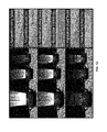
- FIG. 6 isolates simple changes to the individual physical processes, in a simple scene, to illustrate the impact that each process can have on the final shade. Beams are lit with the physically-based definitions of the four physical processes (top), and the effect on the final shade due to simple, isolated procedural modifications to three of the four physical processes (middle and bottom rows). Note that with simple modifications, a large breadth of artistic manipulations can be explored, even with photon beams generated using physically-based emission.
- photon beams can easily handle heterogeneous media as well.
- the attenuation along each beam f b could be computed using a 1D texture (see e.g., FIGS. 5 and 6 ) that stores the accumulated optical depth.
- the attenuation towards the eye f e would also need to compute the transmittance, which could be accomplished using a deep shadow map.
- Automatic setting of physical scattering parameters in heterogeneous media may be within the scope of this disclosure.
- Lighting artists are familiar with tools used for generating such physically-based solutions and some embodiments have implemented a shadow-mapping-based approach to quickly generate single-scattered beams in a scene. While these methods of beam generation are useful for physically-accurate results, in some scenes a stylized volumetric effect is necessary. In these cases art-directable beam generation becomes important.
- FIG. 7 was generated using the 2D illustrations in FIG. 3 as motivation.
- an artist created two turbulent particle simulations and associated a time-dependent path to each particle in the simulation. Particles were chained together to form the beam data used to render the smoke and fire. This entire process was completed by a single artist working with our system.
- the beams in a scene are a geometric lighting primitive that explicitly define the distribution of scattered light in a volume, or more simply, the volume's lit shape.
- This intuitive interpretation provides a key insight when designing a tool for art-directable beam generation.
- Traditional volume rendering includes the problem of defining a field of volumetric shading parameters, but now an artist can instead think of sculpting a volume as if it were a geometric entity; this is a natural 3D extension of the process of hand sketching 2D volumetric effect (see FIG. 3 ).
- FIG. 8 illustrates this approach with light “pouring out of” a door crack and keyhole.
- This is a common lighting scenario in movie production, but unfortunately a notoriously difficult sampling problem for physical simulation. Instead of manually placing lights (in the occluded room) and relying on expensive physical simulation to generate beams, artists are allowed to sculpt this distribution directly. The artist models the beams of light coming through the door with a procedural particle system, distributing points along the crack with the necessary beam attributes (direction, length, power and width). Jittering the beam start points (procedurally) adds to the dramatic effect and the artist can easily add procedural, time-dependent perturbations to animate the beams.
- Procedurally-generated beams can form curved, warped frustra, as opposed to the perfectly conical frustra generated with physically accurate light transport. This is especially common when generating beams from procedural or fluid-based simulation.
- a single photon beam can be interpreted as a spatially-varying volume of light.
- each curved photon beam induces volumetric a bendy light, albeit with a more flexible, art-directable spatial and angular radiance distribution.
- curvy beams slowly fill a room, creating intricate, non-physical lighting both volumetrically and indirectly on surfaces.
- an artist might start with spiral and flower shapes on paper, implement them as curves in the curve handling software, such as the HoudiniTM software, and use them as both paths and target shapes for beams.
- FIG. 1 beams cast light on objects in the scene, as well as being reflected in the environment. Reflections were computed by ray-tracing photon beams as geometry.
- FIG. 9 shows a simpler scene with procedurally-generated beams which induce reflections and indirect diffuse lighting on other surfaces.
- PBGI point-based global illumination
- FIG. 8 illustrates and example door jamb and a keyhole that emit volumetric light.
- the sequence in the top row was created using manually placed, static emissive curve geometry.
- photon beams were created by distributing particles at the door jam and keyhole, animating these beam origins, and shading with our model.
- Lighting was accumulated in a much more natural and predictable manner; the density of painted beams directly mapped to expected intensity variation. More intuitive and fine-grained control over beams was exposed via the beam attributes (e.g., “beamID”) used to steer fall-off, color, intensity, spread and directionality behavior. Beams behave correctly when intersecting the camera plane, eliminating the need for manual flaring composition.
- beam attributes e.g., “beamID”
- FIG. 10 illustrates three animation sequences of a torus, immersed in a volumetric medium, rotating over a blue area light source.
- the top animation sequence was created by an artist familiar with our system.
- the bottom two rows of FIG. 10 are animation sequences generated by a different artist, unfamiliar with our system, first using traditional animation and rendering techniques (as shown in the middle row) and then using our system (as shown in the very bottom row).
- FIG. 11 visualizes (1) the emissive surface geometry used in the original keyhole sequence (on left), and (2) beams generated using a physical simulation in the final keyhole sequence (on right).
- the former technique (on left) required a tedious, manual placement and animation of emissive surfaces, whereas in the automatically-simulated beam geometry (on the right), artists simply “sprinkled” beam seed points along the door cracks and used standard particle simulation tools to evolve the beams over time.
- the most common deviations from physically-based shading involved f b and f e .
- beam attenuation was set according to custom splines and fall-off towards the eye was disabled, whereas the keyhole scene used physical fall-off along beams but non-physical fall-off towards the eye.
- FIG. 12 illustrates the influence of similar changes to f b and f e .
- our system can be implemented on top of almost any existing rendering backend. Any system capable of programmable shading of beam geometry is suitable, whether it be using RiCurves in PRMan, ray-tracing of beam geometry, or rasterization with programmable pixel shaders. Our final results are generated using PRMan's REYES-style renderer, with the exception of a customized ray-tracer used for shadow-ray computation in our experimental PBGI approach. Furthermore, we developed an expression-editing front-end to our shader (see supplemental material for source code) which allows programmable control.
- photon beams are well-suited to many types of volumetric phenomena.
- wispy effects which were traditionally difficult to model with either point primitives or density grids, can be easily authored with beams.
Landscapes
- Engineering & Computer Science (AREA)
- Computer Graphics (AREA)
- Physics & Mathematics (AREA)
- General Physics & Mathematics (AREA)
- Theoretical Computer Science (AREA)
- Architecture (AREA)
- Computer Hardware Design (AREA)
- General Engineering & Computer Science (AREA)
- Software Systems (AREA)
- Image Generation (AREA)
- Processing Or Creating Images (AREA)
Abstract
Description
-
- 1) the model should preferably adhere as closely as possible to abstractions that artists normally use when thinking about volume effects,
- 2) should preferably generate results spanning the entire gamut of believability, from physically accurate to completely art-directed,
- 3) the system ideally integrates as seamlessly as possible into the existing production pipeline, and
- 4) the system ideally exposes flexibility through programmability.
L(x,w)=L s(x,w)+L m(x,w) (Eqn. 1)
L m(x,w)=σs∫o d e −σ
L m(υ)=σsΦp e −σ
C 1=σsΦp e −σ
C 2=σsΦp e −σ
σt=−log(C 2 /C 1) (Eqn. 6A)
σs=(C 1/Φp)(C 1 /C 2)z (Eqn. 6B)
σs=−α log(C 2 /C 1) (Eqn. 7A)
Φs=(C 1/σs)(C 1 /C 2)z (Eqn. 7B)
-
- 1) color change due to attenuation along the beam, fb(v),
- 2) color change due to attenuation towards the eye, fe(z),
- 3) shading depends on the viewing angle, ff (θp), and
- 4) shading is influenced by the photon beam's thickness, ft(u).
f t=Φp k r(u) (Eqn. 9A)
f e =e −σ
f b =e −σ
-
- float x=clamp(y,0.0,1.0);
- return (15.0/16.0)*(1−x*x)*(1−x*x);
-
- float s=clamp(2*u−1−du,−1.0,1.0);
- float t=clamp(2*u−1+du,−1.0,1.0);
- float s3=s*s*s, t3=t*t*t, s5=s3*s*s, t5=t3*t*t;
- return (15.0/16.0)*(t5/5.0−2.0*t3/3.0+t−s5/5.0+2.0*s3/3.0−s)/(t−s);
-
- color sigma_t=sigma_s+sigma_a;
- return color(exp(−comp(sigma_t,0)*dist),
- exp(−comp(sigma_t,1)*dist), exp(−comp(sigma_t,2)*dist));
-
- float eyeDist=length(I);
- float sampleDist=beamLength*v;
- vector Inorm=I/eyeDist;
- vector beamDirnorm=
- normalize(vector “world” (beamDir[0], beamDir[1], beamDir[2]));
- //Beam blur across width and beam ends
- float blur=kernelBiweight(u, du);
- float distancefromend=beamLength−sampleDist;
- if(distancefromend<width)
- blur*=kernelBiweight(1.0−distancefromend/width);
- if(sampleDist<width)
- blur*=kernelBiweight(1.0−sampleDist/width);
- //Inverse sine computation
- float cos_e_b=beamDirnorm.Inorm;
- float invSin=sqrt(1.0−cos_e_b*cos_e_b);
- invSin=1.0/max(EPSILON, invSin);
- Ci=transmittance(eyeDist)*transmittance(sampleDist)*invSin;
- Ci*=boost*power*phase*sigma_s*2.0*blur/width;
- Ci=clamp(Ci, color(0,0,0), color(1.0,1.0,1.0));
Claims (25)
Priority Applications (1)
| Application Number | Priority Date | Filing Date | Title |
|---|---|---|---|
| US13/280,258 US9396580B1 (en) | 2011-06-10 | 2011-10-24 | Programmable system for artistic volumetric lighting |
Applications Claiming Priority (4)
| Application Number | Priority Date | Filing Date | Title |
|---|---|---|---|
| US201161495627P | 2011-06-10 | 2011-06-10 | |
| US13/235,299 US8638331B1 (en) | 2011-09-16 | 2011-09-16 | Image processing using iterative generation of intermediate images using photon beams of varying parameters |
| US13/280,212 US9280848B1 (en) | 2011-10-24 | 2011-10-24 | Rendering images with volumetric shadows using rectified height maps for independence in processing camera rays |
| US13/280,258 US9396580B1 (en) | 2011-06-10 | 2011-10-24 | Programmable system for artistic volumetric lighting |
Publications (1)
| Publication Number | Publication Date |
|---|---|
| US9396580B1 true US9396580B1 (en) | 2016-07-19 |
Family
ID=56381690
Family Applications (1)
| Application Number | Title | Priority Date | Filing Date |
|---|---|---|---|
| US13/280,258 Active 2034-10-10 US9396580B1 (en) | 2011-06-10 | 2011-10-24 | Programmable system for artistic volumetric lighting |
Country Status (1)
| Country | Link |
|---|---|
| US (1) | US9396580B1 (en) |
Cited By (3)
| Publication number | Priority date | Publication date | Assignee | Title |
|---|---|---|---|---|
| US20150145870A1 (en) * | 2013-11-25 | 2015-05-28 | Autodesk, Inc. | Animating sketches via kinetic textures |
| US20220343592A1 (en) * | 2021-04-22 | 2022-10-27 | Shopify Inc. | Systems and methods for modifying lighting in three-dimensional models |
| US20220414975A1 (en) * | 2021-06-29 | 2022-12-29 | Apple Inc. | Techniques for manipulating computer graphical light sources |
Citations (9)
| Publication number | Priority date | Publication date | Assignee | Title |
|---|---|---|---|---|
| US5914807A (en) * | 1995-05-08 | 1999-06-22 | 3D Technology Laboratories, Inc. | Method and system for three-dimensional display of information based on two-photon upconversion |
| US20050243089A1 (en) * | 2002-08-29 | 2005-11-03 | Johnston Scott F | Method for 2-D animation |
| US7423645B2 (en) * | 2005-06-01 | 2008-09-09 | Microsoft Corporation | System for softening images in screen space |
| US20090102843A1 (en) * | 2007-10-17 | 2009-04-23 | Microsoft Corporation | Image-based proxy accumulation for realtime soft global illumination |
| US8009168B2 (en) * | 2007-06-26 | 2011-08-30 | Microsoft Corporation | Real-time rendering of light-scattering media |
| US20120038645A1 (en) * | 2009-04-17 | 2012-02-16 | Peder Norrby | Method for adding shadows to objects in computer graphics |
| US8207968B1 (en) * | 2008-08-29 | 2012-06-26 | Adobe Systems Incorporated | Method and apparatus for irradiance caching in computing indirect lighting in 3-D computer graphics |
| US20130335406A1 (en) * | 2012-06-18 | 2013-12-19 | Dreamworks Animation Llc | Point-based global illumination directional importance mapping |
| US20140267249A1 (en) * | 2013-03-14 | 2014-09-18 | Dreamworks Animation Llc | Shadow contouring process for integrating 2d shadow characters into 3d scenes |
-
2011
- 2011-10-24 US US13/280,258 patent/US9396580B1/en active Active
Patent Citations (9)
| Publication number | Priority date | Publication date | Assignee | Title |
|---|---|---|---|---|
| US5914807A (en) * | 1995-05-08 | 1999-06-22 | 3D Technology Laboratories, Inc. | Method and system for three-dimensional display of information based on two-photon upconversion |
| US20050243089A1 (en) * | 2002-08-29 | 2005-11-03 | Johnston Scott F | Method for 2-D animation |
| US7423645B2 (en) * | 2005-06-01 | 2008-09-09 | Microsoft Corporation | System for softening images in screen space |
| US8009168B2 (en) * | 2007-06-26 | 2011-08-30 | Microsoft Corporation | Real-time rendering of light-scattering media |
| US20090102843A1 (en) * | 2007-10-17 | 2009-04-23 | Microsoft Corporation | Image-based proxy accumulation for realtime soft global illumination |
| US8207968B1 (en) * | 2008-08-29 | 2012-06-26 | Adobe Systems Incorporated | Method and apparatus for irradiance caching in computing indirect lighting in 3-D computer graphics |
| US20120038645A1 (en) * | 2009-04-17 | 2012-02-16 | Peder Norrby | Method for adding shadows to objects in computer graphics |
| US20130335406A1 (en) * | 2012-06-18 | 2013-12-19 | Dreamworks Animation Llc | Point-based global illumination directional importance mapping |
| US20140267249A1 (en) * | 2013-03-14 | 2014-09-18 | Dreamworks Animation Llc | Shadow contouring process for integrating 2d shadow characters into 3d scenes |
Non-Patent Citations (35)
| Title |
|---|
| Angelidis, A., Neyret, F., Singh, K., and Nowrouzezahrai, D., "A controllable, fast and stable basis for vortex based smoke simulation", In SCA, Eurographics Association, (2006), 25-32. |
| Chandrasekar, S., Radiative Transfer. (1960) Dover Publications, New York, New York. |
| Christensen, P. H., "Point-based approximate color bleeding", Pixar Technical Memo, Jul. 1, 2008. |
| Cook, R. L., Carpenter, L., and Catmull, E., "The reyes image rendering architecture", In Computer Graphics (Proceedings of SIGGRAPH 87), (1987), pp. 95-102. |
| Fedkiw, R., Stam, J., and Jensen, H. W., "Visual simulation of smoke", In Proceedings of ACM SIGGRAPH 2001, Computer Graphics Proceedings, Annual Conference Series, (2001), pp. 15-22. |
| Hong, J.-M., Shinar, T., and Fedkiw, R. 2007. Wrinkled flames and cellular patterns. ACM Transactions on Graphics 26, 3 (Jul.), 47:1-47:6. |
| Iman Sadeghi (NPL-An Artist Friendly Hair Shading System, 2010. * |
| Jarosz, W., Nowrouzezahrai, D., Sadeghi, I., and Jensen, H. W. 2011. A comprehensive theory of volumetric radiance estimation using photon points and beams. ACM Transactions on Graphics 30, 1 (Jan.), 5:1-5:19. |
| Jensen, H. W., and Christensen, P. H. 1998. Efficient simulation of light transport in scenes with participating media using photon maps. In Proceedings of SIGGRAPH 98, Computer Graphics Proceedings, Annual Conference Series, 311-320. |
| K{hacek over (r)}ivánek, J., Fajardo, M., Christensen, P. H., Tabellion, E., Bunnell, M., Larsson, D., and Kaplanyan, A. 2010. Global illumination across industries. In SIGGRAPH Courses, ACM. |
| Kajiya, J. T. 1986. The rendering equation. In Computer Graphics (Proceedings of SIGGRAPH 86), 143-150. |
| Kerr, W. B., and Pellacini, F. 2009. Toward evaluating lighting design interface paradigms for novice users. ACM Transactions on Graphics 28, 3 (Jul.), 26:1-26:9. |
| Kerr, W. B., and Pellacini, F. 2010. Toward evaluating material design interface paradigms for novice users. ACM Transactions on Graphics 29, 4 (Jul.), 35:1-35:10. |
| Kerr, W. B., Pellacini, F., and Denning, J. D. 2010. Bendylights: Artistic control of direct illumination by curving light rays. Computer Graphics Forum 29, 4, 1451-1459. |
| McNamara, A., Treuille, A., Popovi{hacek over ( )}c, Z., and Stam, J. 2004. Fluid control using the adjoint method. ACM Transactions on Graphics 23, 3 (Aug.), 449-456. |
| Nowrouzezahrai, D et al., "A Programmable System for Artistic Volumetric Lighting", '11 SIGGRAPH, ACM (Aug. 2011), ACM New York, NY, USA, 8 pages. |
| Nowrouzezahrai, D et al., "A Programmable System for Artistic Volumetric Lighting: Supplemental Document ", '11 SIGGRAPH, ACM (Aug. 2011), ACM New York, NY, USA, 3 pages. |
| Obert, J., K{hacek over ( )}riv´a nek, J., Pellacini, F., S´Ykora, D., and Pattanaik, S. N. 2008. iCheat: A representation for artistic control of indirect cinematic lighting. Computer Graphics Forum 27, 4, 1217-1223. |
| Obert, J., Pellacini, F., and Pattanaik, S. N. 2010. Visibility editing for all-frequency shadow design Comput. Graph. Forum 29, 4, 1441-1449. |
| Pellacini, F. 2010. envylight: An interface for editing natural illumination. ACM Transactions on Graphics 29, 4 (Jul.), 34:1-34:8. |
| Pellacini, F., Battaglia, F., Morley, R. K., and Finkelstein, A. 2007. Lighting with paint. ACM Transactions on Graphics 26, 2 (Jun.), 9:1-9:14. |
| Sadeghi, I., Pritchett, H., Jensen, H. W., and Tamstorf, R. 2010. An artist friendly hair shading system. ACM Transactions on Graphics 29, 4 (Jul.), 56:1-56:10. |
| Schmid, J., Sumner, R. W., Bowles, H., and Gross, M. 2010. Programmable motion effects. ACM Transactions on Graphics 29, 4 (Jul.), 57:1-57:9. |
| Selle, A., Mohr, A., and Chenney, S. 2004. Cartoon rendering of smoke animations. In Non-photorealistic Animation and Rendering, ACM, 57-60. |
| Song, Y., Tong, X., Pellacini, F., and Peers, P. 2009. Subedit: A representation for editing measured heterogeneous subsurface scattering. ACM Transactions on Graphics 28, 3 (Jul.), 31:1-31:10. |
| Tabellion, E., and Lamorlette, A. 2004. An approximate global illumination system for computer generated films. ACM Transactions on Graphics 23, 3 (Aug.), 469-476. |
| Tessendorf, J., and Kowalski, M. 2010. Resolution independent volumes. In ACM SIGGRAPH 2010 Courses, SIGGRAPH. |
| Treuille, A., McNamara, A., Popovíc, Z., and Stam, J. 2003. Keyframe control of smoke simulations. ACM Transactions on Graphics 22, 3 (Jul.), 716-723. |
| U.S. Appl. No. 13/235,299, filed Sep. 16, 2011. |
| U.S. Appl. No. 13/280,212, filed Oct. 24, 2011. |
| Walter, B., Zhao, S., Holzschuch, N., and Bala, K. 2009. Single scattering in refractive media with triangle mesh boundaries. ACM Transactions on Graphics 28, 3 (Jul.), 92:1-92:8. |
| William B. Kerr (NPL-BendyLights: Artistic Control of Direct Illumination by Curving Light Rays, 2010. * |
| Williams, L. 1978. Casting curved shadows on curved surfaces. In Computer Graphics (Proceedings of SIGGRAPH 78), 270-274. |
| Wojciech Jarosz (NPL-A Comprehensive Theory of Volumetric Radiance Estimation using Photon Points and Beams, 2011). * |
| Wojciech Jarosz, The Beam Radiance Estimate for Volumetric Photon Mapping 2008, Blackwell Publishing, vol. 27(2008) , pp. 6, and 7. * |
Cited By (6)
| Publication number | Priority date | Publication date | Assignee | Title |
|---|---|---|---|---|
| US20150145870A1 (en) * | 2013-11-25 | 2015-05-28 | Autodesk, Inc. | Animating sketches via kinetic textures |
| US9734618B2 (en) * | 2013-11-25 | 2017-08-15 | Autodesk, Inc. | Animating sketches via kinetic textures |
| US10410396B2 (en) | 2013-11-25 | 2019-09-10 | Autodesk, Inc. | Animating sketches via kinetic textures |
| US20220343592A1 (en) * | 2021-04-22 | 2022-10-27 | Shopify Inc. | Systems and methods for modifying lighting in three-dimensional models |
| US11847736B2 (en) * | 2021-04-22 | 2023-12-19 | Shopify Inc. | Systems and methods for modifying lighting in three-dimensional models |
| US20220414975A1 (en) * | 2021-06-29 | 2022-12-29 | Apple Inc. | Techniques for manipulating computer graphical light sources |
Similar Documents
| Publication | Publication Date | Title |
|---|---|---|
| Christensen et al. | Renderman: An advanced path-tracing architecture for movie rendering | |
| Nowrouzezahrai et al. | A programmable system for artistic volumetric lighting | |
| Ebert et al. | Texturing and modeling: a procedural approach | |
| Pirk et al. | Plastic trees: interactive self-adapting botanical tree models | |
| US8773433B1 (en) | Component-based lighting | |
| US20060087509A1 (en) | Computer modeling and animation of natural phenomena | |
| US9401043B2 (en) | Photon beam diffusion | |
| PT1376472E (en) | Systems and methods for providing controllable texture sampling | |
| US9189883B1 (en) | Rendering of multiple volumes | |
| Schmidt et al. | Path-space manipulation of physically-based light transport | |
| CN105335996B (en) | A kind of computational methods and device of light radiation response | |
| US9396580B1 (en) | Programmable system for artistic volumetric lighting | |
| Klehm et al. | Property and lighting manipulations for static volume stylization using a painting metaphor | |
| Mamgain | Autodesk 3ds Max 2021: A Detailed Guide to Arnold Renderer | |
| Di Fiore et al. | A framework for user control on stylised animation of gaseous phenomena | |
| Ragan-Kelley | Practical interactive lighting design for RenderMan scenes | |
| Oliveira et al. | Geotextures: a multi-source geodesic distance field approach for procedural texturing of complex meshes | |
| Van der Steen et al. | Rendering with mental ray and 3ds Max | |
| Kol et al. | Expressive single scattering for light shaft stylization | |
| Reimschussel | Rendering Realistic Cloud Effects for Computer Generated Films | |
| Kajs | Real-Time Rendering of Granular Materials | |
| Shesh et al. | Crayon lighting: Sketch-guided illumination of models | |
| Moioli | Understanding Materials, Lighting, and World Settings | |
| Jain | 3D Image Creation With Standard Light Effects | |
| Alda | Distortion Shaders |
Legal Events
| Date | Code | Title | Description |
|---|---|---|---|
| AS | Assignment |
Owner name: THE WALT DISNEY COMPANY (SWITZERLAND) GMBH, SWITZE Free format text: ASSIGNMENT OF ASSIGNORS INTEREST;ASSIGNORS:NOWROUZEZAHRAI, DEREK;WOJCIECH, JAROSZ;JOHNSON, JARED;AND OTHERS;SIGNING DATES FROM 20111028 TO 20111031;REEL/FRAME:027644/0068 |
|
| AS | Assignment |
Owner name: DISNEY ENTERPRISES, INC., CALIFORNIA Free format text: ASSIGNMENT OF ASSIGNORS INTEREST;ASSIGNOR:THE WALT DISNEY COMPANY (SWITZERLAND) GMBH;REEL/FRAME:027974/0942 Effective date: 20120402 |
|
| STCF | Information on status: patent grant |
Free format text: PATENTED CASE |
|
| MAFP | Maintenance fee payment |
Free format text: PAYMENT OF MAINTENANCE FEE, 4TH YEAR, LARGE ENTITY (ORIGINAL EVENT CODE: M1551); ENTITY STATUS OF PATENT OWNER: LARGE ENTITY Year of fee payment: 4 |
|
| MAFP | Maintenance fee payment |
Free format text: PAYMENT OF MAINTENANCE FEE, 8TH YEAR, LARGE ENTITY (ORIGINAL EVENT CODE: M1552); ENTITY STATUS OF PATENT OWNER: LARGE ENTITY Year of fee payment: 8 |