US9383975B1 - Projection of software and integrated circuit diagrams into actual 3D space - Google Patents
Projection of software and integrated circuit diagrams into actual 3D space Download PDFInfo
- Publication number
- US9383975B1 US9383975B1 US14/133,059 US201314133059A US9383975B1 US 9383975 B1 US9383975 B1 US 9383975B1 US 201314133059 A US201314133059 A US 201314133059A US 9383975 B1 US9383975 B1 US 9383975B1
- Authority
- US
- United States
- Prior art keywords
- objects
- subset
- display
- projection
- axis
- Prior art date
- Legal status (The legal status is an assumption and is not a legal conclusion. Google has not performed a legal analysis and makes no representation as to the accuracy of the status listed.)
- Active, expires
Links
- 238000010586 diagram Methods 0.000 title abstract description 13
- 238000000034 method Methods 0.000 claims abstract description 16
- 238000013507 mapping Methods 0.000 claims description 8
- 230000008569 process Effects 0.000 claims description 4
- 238000004891 communication Methods 0.000 claims description 3
- 238000013499 data model Methods 0.000 claims 9
- 230000036962 time dependent Effects 0.000 claims 2
- 230000008447 perception Effects 0.000 abstract 1
- 238000013461 design Methods 0.000 description 5
- 230000000694 effects Effects 0.000 description 4
- 239000011521 glass Substances 0.000 description 4
- 238000013459 approach Methods 0.000 description 3
- 230000008901 benefit Effects 0.000 description 2
- 230000006870 function Effects 0.000 description 2
- 230000007246 mechanism Effects 0.000 description 2
- 230000003245 working effect Effects 0.000 description 2
- 230000008859 change Effects 0.000 description 1
- 230000004044 response Effects 0.000 description 1
Images


Classifications
-
- G—PHYSICS
- G06—COMPUTING; CALCULATING OR COUNTING
- G06F—ELECTRIC DIGITAL DATA PROCESSING
- G06F8/00—Arrangements for software engineering
- G06F8/30—Creation or generation of source code
- G06F8/34—Graphical or visual programming
Definitions
- the present invention relates generally to the projection of any kind of software or integrated circuit diagram into three-dimensional (3D) space allowing for clearer understanding of all details.
- 3D displays of integrated circuits also use perspective drawing techniques on a 2D surface.
- An example is a multi-layered integrated circuit.
- the limitation of this approach is analogous to that of software diagrams, that is complex orthogonal relationships are hard to depict on a 2D surface.
- the present invention provides a full depth 3D experience for such diagrams.
- the 3D effect can be created using stereoscopy (with or without 3D glasses), holograms, or any technique that projects an image into actual 3D space.
- FIG. 1 illustrates projection of a software diagram into actual 3D space
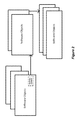
- FIG. 2 illustrates a detailed view of sample 3D software diagram
- FIG. 3 illustrates a detailed view of a sample 3D integrated circuit diagram.
- FIG. 1 illustrates a system using stereoscopy for projecting software diagrams into actual 3D space as opposed to merely drawing a 3D perspective onto a 2D surface.
- the 3D projection is achieved using stereoscopy but could also be achieved with holograms or any other technique that projects an image into actual 3D space.
- the user may or may not be required to wear 3D glasses depending on the mechanism that implements the 3D effect.
- the software diagrams that are most effectively displayed using the present invention are inherently three-dimensional, i.e. information is conveyed using a vertical Z-Axis as well as the horizontal X and Y axes.
- FIG. 2 is an example of such a 3D software diagram.
- FIG. 2 is an abstract representation of objects (for example, functional objects) that map to a series of other objects in response to an operation of a mapping element and each of the objects in the mapped-to series can in turn map to an additional series of objects.
- objects for example, functional objects
- Concrete examples are (1) an object-oriented database, i.e. a database where each record in a table points to a table of other records each of which may point to additional tables; (2) lists of objects currently in memory and their interrelationships. The present invention will project this diagram into actual 3D space.
- a second type of 3D software diagram well-suited to the present invention is one that illustrates the execution of a “parallel programming” application.
- the diagram would display, for example, the operation of concurrent processes, threads, and tasks as well as communications between them.
- a third type of 3D software diagram well-suited to the present invention uses time as the third dimension.
- An example would be the display of variable values in a recursive function during successive calls of the function.
- All of the software components in a 3D projection do not need to be displayed at once.
- the various components can be either not shown at all or shown collapsed with the ability to be expanded as desired.
- An example would be the opening of a table of database records.
- the present invention will allow complete “drill down” capability to allow the user to zero in on those components of interest that may be nested many layers down.
- the 3D display can also be rotated to allow it to be viewed from any angle.
- the user can also “enter” the display so that he sees the software object relationships from the inside. That is, the user can “wander” throughout the structures as if he were inside a building. This effect may or may not require 3D glasses.
- the 3D display can change in real-time in order to reflect changes in the application's state.
- the user can watch software objects as they get populated using both eager and lazy loading. It would also be possible to view intermediate results of certain operations such as nested joins in a database query. Viewing dynamically the internal workings in 3D, especially from within, would help reveal bottlenecks and other design flaws. These are some but not all the real-time viewing scenarios that are possible.
- FIG. 3 is an example of a 3D diagram for integrated circuits.
- the present invention will project this diagram into actual 3D space, allowing all the circuitry with its vertical and horizontal interconnects to be viewed without the obfuscation of 2D perspective.
- This projection would be analogous to the projection of software diagrams. That is, the projection could be implemented with stereoscopy as shown in FIG. 1 or be achieved with holograms or any other technique that projects an image into actual 3D space. The user may or may not be required to wear 3D glasses depending on the mechanism that implements the 3D effect.
- the 3D diagram can be rotated or viewed from any angle.
- the diagram in this case the integrated circuit, can also be “entered”, allowing the user to wander throughout its structure allow the user to detect design flaws.
Abstract
The present invention is a technique of displaying in actual 3D space (i.e. not merely a 3D representation on a 2D surface) any type of diagram relating to software or integrated circuits that requires depth perception in order to be fully comprehended. The 3D space can be manipulated as desired, including but not limited to rotation, collapse/expand, and the ability of the user to enter the 3D space and view it from within.
Description
This application claims benefit of U.S. Patent application 61/849,447 filed 28 Jan. 2013, the contents of which are hereby expressly incorporated herein in their entirety for all purposes.
The present invention relates generally to the projection of any kind of software or integrated circuit diagram into three-dimensional (3D) space allowing for clearer understanding of all details.
Current 3D display of software diagrams is done using perspective drawing techniques on a two dimensional (2D) surface. An example is an exploded list of software objects (such as a table of database records). The main limitation of this approach is that each software object (e.g., database record) may be connected to additional objects (e.g. other database records) which may in turn have further connections ad infinitum (as in an object-oriented database). These complex orthogonal relationships are hard to depict on a 2D surface, making it difficult to visualize the operation of the entire system.
Similarly, 3D displays of integrated circuits also use perspective drawing techniques on a 2D surface. An example is a multi-layered integrated circuit. The limitation of this approach is analogous to that of software diagrams, that is complex orthogonal relationships are hard to depict on a 2D surface.
In view of the foregoing disadvantages inherent in the known types of display of software and integrated circuit diagrams, the present invention provides a full depth 3D experience for such diagrams. The 3D effect can be created using stereoscopy (with or without 3D glasses), holograms, or any technique that projects an image into actual 3D space.
Turning now to the drawings, FIG. 1 illustrates a system using stereoscopy for projecting software diagrams into actual 3D space as opposed to merely drawing a 3D perspective onto a 2D surface.
In FIG. 1 , the 3D projection is achieved using stereoscopy but could also be achieved with holograms or any other technique that projects an image into actual 3D space. The user may or may not be required to wear 3D glasses depending on the mechanism that implements the 3D effect.
The software diagrams that are most effectively displayed using the present invention are inherently three-dimensional, i.e. information is conveyed using a vertical Z-Axis as well as the horizontal X and Y axes.
A second type of 3D software diagram well-suited to the present invention is one that illustrates the execution of a “parallel programming” application. The diagram would display, for example, the operation of concurrent processes, threads, and tasks as well as communications between them.
A third type of 3D software diagram well-suited to the present invention uses time as the third dimension. An example would be the display of variable values in a recursive function during successive calls of the function.
In general, all software diagrams where depth is important can benefit from being projected into actual 3D space using the present invention.
All of the software components in a 3D projection do not need to be displayed at once. The various components can be either not shown at all or shown collapsed with the ability to be expanded as desired. An example would be the opening of a table of database records. The present invention will allow complete “drill down” capability to allow the user to zero in on those components of interest that may be nested many layers down.
The 3D display can also be rotated to allow it to be viewed from any angle.
The user can also “enter” the display so that he sees the software object relationships from the inside. That is, the user can “wander” throughout the structures as if he were inside a building. This effect may or may not require 3D glasses.
The above techniques of display manipulation are not the only ones possible but serve as an illustration.
As an application executes, the 3D display can change in real-time in order to reflect changes in the application's state. For example, in an object-oriented data base, the user can watch software objects as they get populated using both eager and lazy loading. It would also be possible to view intermediate results of certain operations such as nested joins in a database query. Viewing dynamically the internal workings in 3D, especially from within, would help reveal bottlenecks and other design flaws. These are some but not all the real-time viewing scenarios that are possible.
There will also exist a “2D” mode where all the above features are available but are instead shown on a 2D surface with all the limitations of a 2D display.
3D Integrated Circuit Diagrams
This projection would be analogous to the projection of software diagrams. That is, the projection could be implemented with stereoscopy as shown in FIG. 1 or be achieved with holograms or any other technique that projects an image into actual 3D space. The user may or may not be required to wear 3D glasses depending on the mechanism that implements the 3D effect.
Just as in the 3D software diagrams, all the components of the 3D integrated circuit do not need to be displayed at once. It will be possible to collapse certain components and then “drill down” to those of interest.
Also like the 3D projection of software diagrams, the 3D diagram can be rotated or viewed from any angle. The diagram, in this case the integrated circuit, can also be “entered”, allowing the user to wander throughout its structure allow the user to detect design flaws.
The above techniques of display manipulation are not the only ones possible but serve as an illustration.
It would also be possible to simulate the execution of the integrated circuit, showing the voltages at various nodes and times depending on location, lead lengths, etc. Viewing the internal workings in real 3D would allow the user to optimize the design.
There will also exist a “2D” mode where all the above features are available but are instead shown on a 2D surface with all the limitations of a 2D display.
Other Kinds of 3D Design
The above described approach to using 3D projection could also be applied to any form of design, such as aircraft, automobiles, ships, hand tools etc.
Claims (5)
1. A computer-implemented method for a three-dimensional projection of a set of objects onto a display supporting multiple depths, each object including an X axis, a Y axis, and a Z axis, comprising:
a) presenting a first subset of objects on the display at a first particular display depth, a functional object in said first subset of objects including a mapping element wherein said first subset of objects is selected from the set of objects;
b) detecting a user selection of said mapping element triggering a projection event; and
c) presenting, responsive to said projection event, a second subset of objects on the display at a second particular display depth different from said first particular display depth, wherein said second subset of objects is selected from the set of objects;
wherein the three-dimensional projection includes a data model including the set of objects, said data model including a set of predetermined relationships between said first subset of objects and said second subset of objects wherein one or more relationships of said set of predetermined relationships are visualized by said presenting step c);
wherein said data model includes a dynamic parallel processing model including a first plurality of processes within said first subset of objects, a second plurality of processes within said second subset of objects, and wherein said predetermined relationships includes communications between said processes of said first subset of objects and said second subset of objects.
2. A computer-implemented method for a three-dimensional projection of a set of objects onto a display supporting multiple depths, each object including an X axis, a Y axis, and a Z axis, comprising:
a) presenting a first subset of objects on the display at a first particular display depth, a functional object in said first subset of objects including a mapping element wherein said first subset of objects is selected from the set of objects;
b) detecting a user selection of said mapping element triggering a projection event; and
c) presenting, responsive to said projection event, a second subset of objects on the display at a second particular display depth different from said first particular display depth, wherein said second subset of objects is selected from the set of objects;
wherein the three-dimensional projection includes a data model including the set of objects, said data model including a set of predetermined relationships between said first subset of objects and said second subset of objects wherein one or more relationships of said set of predetermined relationships are visualized by said presenting step c);
wherein said data model includes an integrated circuit model, wherein the set of objects includes integrated circuit component representations of functional elements of said integrated circuit model, wherein said first subset of objects include a first subset of integrated circuit components, wherein said second subset of objects includes a second subset of integrated circuit components of said integrated circuit model, and wherein said predetermined relationships represent electrical communication between components of said first subset and associated electrical components of said second subset.
3. The computer-implemented model of claim 2 wherein a particular one electronic component of said first subset includes said mapping element, wherein said particular one electronic component is electrically associated with said second subset of objects, and wherein said projection event of said particular electronic component projects said second plurality of components with the display visualizing said electrical associations.
4. The computer implemented method of claim 3 wherein said electrical associations includes dynamic associations of states of the set of objects, including one or more of simulated voltage values at one or more selected nodes at one or more selected times.
5. A computer-implemented method for a three-dimensional projection of a set of objects onto a display supporting multiple depths, each object including an X axis, a Y axis, and a Z axis, comprising:
a) presenting a first subset of objects on the display at a first particular display depth, a functional object in said first subset of objects including a mapping element wherein said first subset of objects is selected from the set of objects;
b) detecting a user selection of said mapping element triggering a projection event; and
c) presenting, responsive to said projection event, a second subset of objects on the display at a second particular display depth different from said first particular display depth, wherein said second subset of objects is selected from the set of objects;
wherein the three-dimensional projection includes a data model including the set of objects, said data model including a set of predetermined relationships between said first subset of objects and said second subset of objects wherein one or more relationships of said set of predetermined relationships are visualized by said presenting step c);
wherein data model includes a dynamic recursive processing model, wherein the plurality of data objects includes a recursive function generating a series of variable values from a series of successive calls to said recursive function, wherein said first subset of objects includes a first time-dependent value for said variable value responsive to a first particular one successive call of said series of successive calls, and wherein said second subset of objects includes a second time-dependent value for said variable value responsive to a second particular one successive call of said series of successive calls, said second particular one successive call next is said series to said first particular one successive call.
Priority Applications (2)
| Application Number | Priority Date | Filing Date | Title |
|---|---|---|---|
| US14/133,059 US9383975B1 (en) | 2013-01-28 | 2013-12-18 | Projection of software and integrated circuit diagrams into actual 3D space |
| US15/157,252 US20160306730A1 (en) | 2013-01-28 | 2016-05-17 | Projection of software and integrated circuit diagrams into actual 3D space |
Applications Claiming Priority (2)
| Application Number | Priority Date | Filing Date | Title |
|---|---|---|---|
| US201361849447P | 2013-01-28 | 2013-01-28 | |
| US14/133,059 US9383975B1 (en) | 2013-01-28 | 2013-12-18 | Projection of software and integrated circuit diagrams into actual 3D space |
Related Child Applications (1)
| Application Number | Title | Priority Date | Filing Date |
|---|---|---|---|
| US15/157,252 Continuation-In-Part US20160306730A1 (en) | 2013-01-28 | 2016-05-17 | Projection of software and integrated circuit diagrams into actual 3D space |
Publications (1)
| Publication Number | Publication Date |
|---|---|
| US9383975B1 true US9383975B1 (en) | 2016-07-05 |
Family
ID=56234898
Family Applications (1)
| Application Number | Title | Priority Date | Filing Date |
|---|---|---|---|
| US14/133,059 Active 2034-08-13 US9383975B1 (en) | 2013-01-28 | 2013-12-18 | Projection of software and integrated circuit diagrams into actual 3D space |
Country Status (1)
| Country | Link |
|---|---|
| US (1) | US9383975B1 (en) |
Citations (6)
| Publication number | Priority date | Publication date | Assignee | Title |
|---|---|---|---|---|
| US20100198786A1 (en) * | 2009-02-02 | 2010-08-05 | Takahiro Imamichi | Information processing apparatus, information processing method, and computer program product |
| US20100251170A1 (en) * | 2009-03-26 | 2010-09-30 | Apple Inc. | Interface Navigation Tools |
| US20100257450A1 (en) * | 2009-04-03 | 2010-10-07 | Social Communications Company | Application sharing |
| US20100299364A1 (en) * | 2006-10-20 | 2010-11-25 | Peter Jeremy Baldwin | Web application for debate maps |
| WO2013057649A1 (en) | 2011-10-20 | 2013-04-25 | Koninklijke Philips Electronics N.V. | Holographic user interfaces for medical procedures |
| EP2602608A1 (en) | 2011-12-07 | 2013-06-12 | Imec | Analysis and sorting of biological cells in flow |
-
2013
- 2013-12-18 US US14/133,059 patent/US9383975B1/en active Active
Patent Citations (6)
| Publication number | Priority date | Publication date | Assignee | Title |
|---|---|---|---|---|
| US20100299364A1 (en) * | 2006-10-20 | 2010-11-25 | Peter Jeremy Baldwin | Web application for debate maps |
| US20100198786A1 (en) * | 2009-02-02 | 2010-08-05 | Takahiro Imamichi | Information processing apparatus, information processing method, and computer program product |
| US20100251170A1 (en) * | 2009-03-26 | 2010-09-30 | Apple Inc. | Interface Navigation Tools |
| US20100257450A1 (en) * | 2009-04-03 | 2010-10-07 | Social Communications Company | Application sharing |
| WO2013057649A1 (en) | 2011-10-20 | 2013-04-25 | Koninklijke Philips Electronics N.V. | Holographic user interfaces for medical procedures |
| EP2602608A1 (en) | 2011-12-07 | 2013-06-12 | Imec | Analysis and sorting of biological cells in flow |
Non-Patent Citations (6)
| Title |
|---|
| Addy Dugdale, "Holograms are coming to the classroom", Jun. 18, 2013 [Online] downloaded from: http://www.fastcompany.com/3013158/fast-feed/holograms-are-coming-to-the-classroom on Mar. 9, 2014. |
| Leandro Soares Indrusiak et al., "3D integrated circuit layout visualization using VRML" Best of Websim 99, Future Generation Computer Systems 17, pp. 503-511 (2001). |
| Robin A Walker 2013 J. Phys.: Conf. Ser. 415 012076, Holograms as Teaching Agents, downloaded from http://iopscience.iop.org/1742-6596/415/1/012076 on Mar. 9, 2014. |
| Stanford University News Service, Engineers will soon use 'virtual reality' to design computer chips' News Release Mar. 21, 1995, url: http://news.stanford.edu/pr/95/950321Arc5314.html printed Jun. 6, 2016. |
| Tung H. Jeong, "Teaching Advanced physical concepts using display holograms", The 8th International Symposium on Display Holography (ISDH 2009) held at Shenzhen, China Jul. 13-17, 2009 [Online]-Downloaded from http://river-valley.tv/teaching-advanced-physical-concepts-using-display-holograms/ on Mar. 9, 2014. |
| Tung H. Jeong, "Teaching Advanced physical concepts using display holograms", The 8th International Symposium on Display Holography <http://www.isdh.org.cn/en/index.asp> (ISDH 2009) held at Shenzhen, China Jul. 13-17, 2009 [Online]-Downloaded from http://river-valley.tv/teaching-advanced-physical-concepts-using-display-holograms/ on Mar. 9, 2014. |
Similar Documents
| Publication | Publication Date | Title |
|---|---|---|
| US9292972B2 (en) | Occupant centric capture and visualization of building performance data | |
| US20120259594A1 (en) | Bim based 3-d visualization | |
| US8319792B2 (en) | Virtual components for CAD models | |
| Zhu et al. | A new reconstruction method for 3D buildings from 2D vector floor plan | |
| Butkiewicz et al. | Multi-focused geospatial analysis using probes | |
| CN103886638A (en) | Simulation Of The Physical Behavior Of An Object In A 3d Scene Divided Into A Plurality Of Zones | |
| US9460561B1 (en) | Hypermodel-based panorama augmentation | |
| EP3252628A1 (en) | Selection control method, selection control device, and selection control program | |
| CN111563357B (en) | Three-dimensional visual display method and system for electronic device | |
| CN110021060A (en) | One kind carrying out computer room 3D visualization method and device based on Unity3D engine | |
| Beneš et al. | Efficient methods to visualize finite element meshes | |
| US9383975B1 (en) | Projection of software and integrated circuit diagrams into actual 3D space | |
| US10746889B2 (en) | Method for estimating faults in a three-dimensional seismic image block | |
| Sorger et al. | A Taxonomy of Integration Techniques for Spatial and Non-Spatial Visualizations. | |
| US9230366B1 (en) | Identification of dynamic objects based on depth data | |
| Musliman et al. | 3D navigation for 3D-GIS—Initial requirements | |
| Bogdahn et al. | Towards an automated healing of 3D urban models | |
| Lee et al. | Dynamic architectural visualization based on user-centered semantic interoperability | |
| Li et al. | New views on multivariable spatiotemporal data: the space time cube expanded | |
| US20160306730A1 (en) | Projection of software and integrated circuit diagrams into actual 3D space | |
| CN107547604B (en) | Article display method and system | |
| CN108062786B (en) | Comprehensive perception positioning technology application system based on three-dimensional information model | |
| KR100610756B1 (en) | A computer aided structure analysis and design graphic display device displaying a joint status by a numerical data | |
| CN104408184A (en) | Two-dimensional visual data display method and device based on data cubes | |
| WO2018009170A1 (en) | Projection of software and integrated circuit diagrams into actual 3d space |
Legal Events
| Date | Code | Title | Description |
|---|---|---|---|
| STCF | Information on status: patent grant |
Free format text: PATENTED CASE |
|
| MAFP | Maintenance fee payment |
Free format text: PAYMENT OF MAINTENANCE FEE, 4TH YEAR, MICRO ENTITY (ORIGINAL EVENT CODE: M3551); ENTITY STATUS OF PATENT OWNER: MICROENTITY Year of fee payment: 4 |
|
| MAFP | Maintenance fee payment |
Free format text: PAYMENT OF MAINTENANCE FEE, 8TH YEAR, MICRO ENTITY (ORIGINAL EVENT CODE: M3552); ENTITY STATUS OF PATENT OWNER: MICROENTITY Year of fee payment: 8 |