US9336963B1 - Interlock assembly for network transformer primary disconnect assembly - Google Patents
Interlock assembly for network transformer primary disconnect assembly Download PDFInfo
- Publication number
- US9336963B1 US9336963B1 US14/532,239 US201414532239A US9336963B1 US 9336963 B1 US9336963 B1 US 9336963B1 US 201414532239 A US201414532239 A US 201414532239A US 9336963 B1 US9336963 B1 US 9336963B1
- Authority
- US
- United States
- Prior art keywords
- assembly
- blocking member
- contact carriage
- carriage
- ground contact
- Prior art date
- Legal status (The legal status is an assumption and is not a legal conclusion. Google has not performed a legal analysis and makes no representation as to the accuracy of the status listed.)
- Active, expires
Links
- 230000000903 blocking effect Effects 0.000 claims abstract description 153
- 230000007935 neutral effect Effects 0.000 claims abstract description 23
- 238000000429 assembly Methods 0.000 claims description 147
- 230000000712 assembly Effects 0.000 claims description 147
- 230000008878 coupling Effects 0.000 description 35
- 238000010168 coupling process Methods 0.000 description 35
- 238000005859 coupling reaction Methods 0.000 description 35
- 230000008595 infiltration Effects 0.000 description 10
- 238000001764 infiltration Methods 0.000 description 10
- 239000007788 liquid Substances 0.000 description 8
- 239000004020 conductor Substances 0.000 description 7
- 239000011810 insulating material Substances 0.000 description 5
- 239000000463 material Substances 0.000 description 5
- 230000001012 protector Effects 0.000 description 5
- 239000003086 colorant Substances 0.000 description 3
- 238000012423 maintenance Methods 0.000 description 3
- XLYOFNOQVPJJNP-UHFFFAOYSA-N water Substances O XLYOFNOQVPJJNP-UHFFFAOYSA-N 0.000 description 3
- BQCADISMDOOEFD-UHFFFAOYSA-N Silver Chemical compound [Ag] BQCADISMDOOEFD-UHFFFAOYSA-N 0.000 description 2
- 239000011159 matrix material Substances 0.000 description 2
- 229910052709 silver Inorganic materials 0.000 description 2
- 239000004332 silver Substances 0.000 description 2
- 238000011144 upstream manufacturing Methods 0.000 description 2
- RYGMFSIKBFXOCR-UHFFFAOYSA-N Copper Chemical compound [Cu] RYGMFSIKBFXOCR-UHFFFAOYSA-N 0.000 description 1
- 241000238631 Hexapoda Species 0.000 description 1
- 241000270295 Serpentes Species 0.000 description 1
- 229910052802 copper Inorganic materials 0.000 description 1
- 239000010949 copper Substances 0.000 description 1
- 239000012530 fluid Substances 0.000 description 1
- PCHJSUWPFVWCPO-UHFFFAOYSA-N gold Chemical compound [Au] PCHJSUWPFVWCPO-UHFFFAOYSA-N 0.000 description 1
- 239000010931 gold Substances 0.000 description 1
- 229910052737 gold Inorganic materials 0.000 description 1
- 238000005286 illumination Methods 0.000 description 1
- 229910052751 metal Inorganic materials 0.000 description 1
- 239000002184 metal Substances 0.000 description 1
- 150000002739 metals Chemical class 0.000 description 1
- 238000012986 modification Methods 0.000 description 1
- 230000004048 modification Effects 0.000 description 1
- 239000004033 plastic Substances 0.000 description 1
- 229920003023 plastic Polymers 0.000 description 1
- 239000004417 polycarbonate Substances 0.000 description 1
- 229920000515 polycarbonate Polymers 0.000 description 1
- 238000000926 separation method Methods 0.000 description 1
- 231100000611 venom Toxicity 0.000 description 1
Images


Classifications
-
- H—ELECTRICITY
- H01—ELECTRIC ELEMENTS
- H01H—ELECTRIC SWITCHES; RELAYS; SELECTORS; EMERGENCY PROTECTIVE DEVICES
- H01H9/00—Details of switching devices, not covered by groups H01H1/00 - H01H7/00
- H01H9/20—Interlocking, locking, or latching mechanisms
-
- H—ELECTRICITY
- H01—ELECTRIC ELEMENTS
- H01H—ELECTRIC SWITCHES; RELAYS; SELECTORS; EMERGENCY PROTECTIVE DEVICES
- H01H9/00—Details of switching devices, not covered by groups H01H1/00 - H01H7/00
- H01H9/20—Interlocking, locking, or latching mechanisms
- H01H9/26—Interlocking, locking, or latching mechanisms for interlocking two or more switches
-
- H—ELECTRICITY
- H02—GENERATION; CONVERSION OR DISTRIBUTION OF ELECTRIC POWER
- H02B—BOARDS, SUBSTATIONS OR SWITCHING ARRANGEMENTS FOR THE SUPPLY OR DISTRIBUTION OF ELECTRIC POWER
- H02B5/00—Non-enclosed substations; Substations with enclosed and non-enclosed equipment
-
- H—ELECTRICITY
- H01—ELECTRIC ELEMENTS
- H01H—ELECTRIC SWITCHES; RELAYS; SELECTORS; EMERGENCY PROTECTIVE DEVICES
- H01H33/00—High-tension or heavy-current switches with arc-extinguishing or arc-preventing means
- H01H33/02—Details
- H01H33/46—Interlocking mechanisms
- H01H33/52—Interlocking mechanisms for interlocking two or more switches
Definitions
- the disclosed and claimed concept relates to a network transformer primary disconnect assembly and, more particularly to an interlock assembly for a network transformer primary disconnect assembly.
- the primary medium voltage disconnect must be structured to be coupled to either the medium voltage vacuum circuit breaker or a ground conductor assembly. That is, when the network transformer is in operation, the primary medium voltage disconnect must be coupled to, and in electrical communication with, the medium voltage vacuum circuit breaker which is further coupled to, and in electrical communication with the network transformer. During maintenance, however, the primary medium voltage disconnect must be grounded so as to ground the upstream medium voltage distribution switchgear. An interlock assembly is needed to ensure that the primary medium voltage disconnect cannot be coupled to both the medium voltage vacuum circuit breaker and the ground conductor assembly at the same time.
- the submersible housing assembly needs to be able to reveal the configuration of the primary medium voltage disconnect.
- the network transformer primary disconnect assembly includes a housing assembly and a circuit interrupter.
- the housing assembly includes a number of sidewalls defining an enclosed space.
- the circuit interrupter includes a number of operational contact assemblies and a number of ground contact assemblies.
- the interlock assembly includes a mechanical interlock assembly with an operation assembly, a ground assembly, and a blocking member assembly.
- the operation assembly includes a movable operation contact carriage. The operation contact carriage is movable over a path between a first position and a second position.
- the ground assembly includes a movable ground contact carriage. The ground contact carriage is movable over a path between a first position and a second position.
- FIG. 4 is a cross-sectional side view of a circuit breaker and an interlock assembly in a housing assembly wherein the circuit breaker contact assemblies are in a first position, the interlock assembly operation contact assemblies are in a second position and the interlock ground contact assemblies are in a first position.
- FIG. 5 is a cross-sectional side view of a circuit breaker and an interlock assembly in a housing assembly wherein the circuit breaker contact assemblies are in a first position, the interlock assembly operation contact assemblies are in a first position and the interlock ground contact assemblies are in a first position.
- FIG. 7 is a top view of an interlock assembly.
- FIG. 8 is a side view of an interlock assembly.
- FIG. 9 is a side view of an interlock assembly with the contact assemblies removed.
- FIG. 15 is a top cross-sectional view of a housing assembly and portions of an interlock assembly.
- a “coupling assembly” includes two or more couplings or coupling components.
- the components of a coupling or coupling assembly are generally not part of the same element or other component. As such, the components of a “coupling assembly” may not be described at the same time in the following description.
- a “coupling” or “coupling component(s)” is one or more component(s) of a coupling assembly. That is, a coupling assembly includes at least two components that are structured to be coupled together. It is understood that the components of a coupling assembly are compatible with each other. For example, in a coupling assembly, if one coupling component is a snap socket, the other coupling component is a snap plug, or, if one coupling component is a bolt, then the other coupling component is a nut.
- “Substantially correspond” means that the size of the opening is very close to the size of the element inserted therein; that is, not so close as to cause substantial friction, as with a snug fit, but with more contact and friction than a “corresponding fit,” i.e., a “slightly larger” fit.
- unitary means a component is created as a single piece or unit. That is, a component that includes pieces that are created separately and then coupled together as a unit is not a “unitary” component or body.
- number shall mean one or an integer greater than one (i.e., a plurality).
- substantially resistant to liquid infiltration means exposure to about 3 meters of head water above the top of the enclosure for 24 hours without leaks. This generally corresponds to 35 kPa or 5 psi external pressure.
- a “contact assembly” includes a conductive member and a conductive coupling.
- the conductive member is coupled to, and in electrical communication with, the conductive coupling.
- the conductive coupling is structured to be selectively coupled to, and in electrical communication with, another conductive coupling.
- a conductive coupling includes, but is not limited to, a disk that is structured to engage another disk.
- a conductive coupling includes a resilient spring-like clamp into which a planar member (a stab) is inserted.
- a “pair of contact assemblies” or “pair of ⁇ name> contact assemblies” means a first contact assembly and a second contact assembly wherein the first and second contact assemblies move between two positions, a first position, wherein the contact assemblies are separated and are not in electrical communication, and a second position wherein the contact assemblies are coupled, or directly coupled, and are in electrical communication.
- One or both of the contact assemblies are movable. That is, one contact assembly may be fixed and only the other contact assembly moves between the first and second position.
- the slidable conductive couplings 39 include conductive tubular collars and conductive coils (not shown).
- the tubular collars have a number of groves (not shown) disposed on the inner surface thereof.
- the conductive coils which in an exemplary embodiment are resilient and spring-like, are shaped into a loop and disposed within the grooves.
- the inner cross-sectional area of the tubular collars is greater than the cross-sectional area of the conductive members 36 .
- the inner cross-sectional area of the conductive coils loops is slightly less than the cross-sectional area of the conductive members 36 .
- the circuit interrupter 42 includes a number of contact assemblies 46 on both the line side and the load side of the internal contact assemblies 48 .
- the following discussion addresses only those circuit interrupter contact assemblies 46 that are structured to be, and are, coupled to and in electrical communication with the interlock assembly 70 .
- the circuit interrupter contact assemblies 46 that are structured to be, and are, coupled to and in electrical communication with the interlock assembly 70 may be either the line or the load circuit interrupter contact assemblies 46 depending upon whether the network transformer primary disconnect assembly 14 is structured to ground the medium voltage distribution switchgear 12 or the transformer 16 , as described above. In an exemplary embodiment as shown, the line side circuit interrupter contact assemblies 46 are used.
- the operation assembly 72 includes a movable operation contact carriage assembly 80 , a carriage drive assembly 81 , and a number of operation contact assemblies 82 .
- Each operation assembly operation contact assembly 82 (hereinafter “operation contact assembly” 82 ) has an associated circuit interrupter operation contact assembly 50 .
- the operation assembly 72 includes a number of pairs of operation contact assemblies 84 . That is, each pair of operation contact assemblies 84 includes a circuit interrupter operation contact assembly 50 and an associated operation assembly operation contact assembly 82 .
- the operation contact carriage assembly 80 includes, in an exemplary embodiment, a body 90 having an elongated first portion 92 and an elongated second portion 94 .
- the operation contact carriage body first portion 92 and the operation contact carriage body second portion 94 are disposed generally perpendicular to each other.
- the operation contact carriage assembly operation contact carriage body 90 (or “operation contact carriage” 90 ) has a T-shaped configuration.
- the operation contact carriage 90 is generally planar.
- the planar operation contact carriage 90 is movable disposed in the housing assembly 30 with the plane of the operation contact carriage 90 extending generally horizontally.
- each operation assembly operation contact assembly 82 extends generally vertically and downwardly from the operation contact carriage 90 .
- the housing assembly 30 includes a number of guide members 120 .
- the housing assembly guide members 120 include vertically extending guide surfaces 122 .
- the housing assembly guide members 120 include elongated members that are disposed generally vertically within, and are coupled to, the housing assembly 30 .
- the housing assembly guide members 120 are disposed adjacent the operation contact carriage 90 and are structured to maintain the operation contact carriage 90 in a generally vertical path as discussed below.
- the operation contact carriage 90 includes a number of passages and the housing assembly guide members 120 are elongated rods that correspond to, and pass through, the passages.
- each ground contact assembly 182 moves between a first position, wherein the ground contact assembly 182 is spaced from, and not in electrical communication with, the associated circuit interrupter ground contact assembly 52 , and a second position, wherein the ground contact assembly 182 is coupled or directly coupled to, and in electrical communication with, the associated circuit interrupter ground contact assembly 52 .
- each ground assembly ground contact assembly 182 is an elongated, generally cylindrical rod sized to correspond to the circuit interrupter contact assemblies enclosed space 49 .
- the ground contact carriage assembly 180 includes, in an exemplary embodiment, a body 190 having an elongated first portion 192 and an elongated second portion 194 .
- the ground contact carriage body first portion 192 and the ground contact carriage body second portion 194 are disposed generally perpendicular to each other.
- the contact carriage assembly ground contact carriage body 190 (or “ground contact carriage” 190 ) has a T-shaped configuration.
- the ground contact carriage 190 is generally planar. As shown, the planar the ground contact carriage 190 is movable disposed in the housing assembly 30 with the plane of the ground contact carriage 190 extending generally horizontally. Further, each ground assembly ground contact assembly 182 extends generally vertically and downwardly from the ground contact carriage 190 .
- the ground contact carriage assembly 180 in an exemplary embodiment, includes insulating members (not shown) between the ground contact carriage 190 and each ground assembly operation contact assembly 182 .
- the ground contact carriage body 90 includes a threaded drive passage 195 and a number of guide surfaces 196 .
- the ground contact carriage body drive passage 195 and guide surfaces 196 interact with the ground assembly carriage drive assembly 18181 .
- the housing assembly 30 includes a number of guide members 120 .
- the housing assembly guide members 120 are also disposed adjacent the ground contact carriage 190 and are structured to maintain the ground contact carriage 190 in a generally vertical path as discussed below.
- the ground contact carriage 190 includes a number of passages and the housing assembly guide members 120 are elongated rods that correspond to, and pass through, the passages.
- each ground assembly ground contact assembly 182 is coupled, directly coupled, or fixed to the ground contact carriage 190 and extend generally vertically and downwardly therefrom.
- each ground contact assembly 182 includes a distal portion 183 located opposite the ground contact carriage 190 .
- the ground contact carriage 190 is threadably coupled to the ground assembly carriage drive assembly threaded rod 200 .
- the ground contact carriage 190 is further positioned with the ground contact carriage body guide surfaces 196 abutting, and slidably engaging, the housing assembly guide members 120 .
- each ground assembly ground contact assembly 182 is aligned with an associated circuit interrupter ground contact assembly 52 .
- each ground assembly ground contact assembly 182 moves between an open, first position, wherein the ground assembly ground contact assembly 182 is spaced from the associated circuit interrupter ground contact assembly 52 , and a closed, second position, wherein the ground assembly ground contact assembly 182 is coupled to, and in electrical communication with, the associated circuit interrupter ground contact assembly 52 .
- the blocking member assembly 76 is structured to ensure that only one of either the operation contact assemblies 82 or the ground contact assemblies 182 are in the second position at one time.
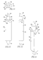
- the blocking member assembly 76 includes a body 130 , shown in FIGS. 11-14 , with an obstruction portion 132 and a lacunar portion 134 .
- a “lacunar portion” is a missing portion; that is, the lacunar portion 134 is empty, but is defined by the maximum dimensions of the blocking member assembly body 130 . That is, any space beyond the maximum dimensions of the blocking member assembly body 130 is not a “lacunar portion,” but, a space within the maximum dimensions of blocking member assembly body 130 is a “lacunar portion.”
- the blocking member assembly body 130 is elongated and has an axis of rotation.
- the blocking member assembly body obstruction portion 132 (hereinafter “obstruction portion” 132 ) is elongated and includes a generally D-shaped cross-section ( FIG. 14 ).
- the blocking member assembly body 130 axis of rotation in an exemplary embodiment, is disposed adjacent the center of the vertical stroke of the “D” shape.
- the blocking member assembly body 130 further includes an axle member 136 .
- the axle member 136 is an elongated member having a generally circular cross-section. Further, the axle member 136 cross-sectional area is less than the blocking member assembly body obstruction portion 132 .
- the blocking member assembly body 130 axis of rotation in an exemplary embodiment, is disposed along the longitudinal axis of the axle member 136 .
- the maximum length of the blocking member assembly body 130 is the length of the elongated obstruction portion 132 and the elongated axle member 136 .
- the obstruction portion 132 defines the maximum cross-sectional dimensions of the blocking member assembly body 130 .
- the maximum dimensions of the blocking member assembly body 130 are defined by the cross-sectional dimensions of the blocking member assembly body 130 and the overall length of the blocking member assembly body 130 .
- the blocking member assembly body lacunar portion 134 (hereinafter “lacunar portion” 134 ) is the empty space disposed about the axle member 136 . That is, the space disposed about the axle member 136 is within the maximum dimensions of the blocking member assembly body 130 but is empty.
- the lacunar portion 134 and therefore the axle member 136 , is disposed at the upper end of the obstruction portion 132 .
- both the axle member 136 and the lower axle member 137 are tiered constructs. That is, each of the axle member 136 and the lower axle member 137 have a wide radius portion 138 and a narrow radius portion 139 .
- the obstruction portion 132 includes an axial surface 140 .
- an “axial surface” or “axial side” extends perpendicular to the longitudinal axis.
- the obstruction portion axial surface 140 includes a first helical portion 142 and a second helical portion 144 .
- the obstruction portion axial surface first and second helical portions 142 , 144 extend away from the lacunar portion 134 and have opposing directions. That is, as shown, the obstruction portion axial surface first helical portion 142 has a left hand direction and the obstruction portion axial surface second helical portion 144 has a right hand direction.
- the twist of the first helical portion 142 and the second helical portion 144 are opposite of each other.
- the first helical portion 142 and the second helical portion 144 are structured to be, and are, camming surfaces 143 , 145 , as described below.
- the obstruction portion axial surface 140 includes a flat 146 , i.e. a surface that extends in a plane generally perpendicular to the blocking member assembly body 130 axis of rotation.
- the blocking member assembly 76 further includes a support assembly 150 .
- the blocking member assembly support assembly 150 (hereinafter “support assembly” 150 ) includes two generally planar support member bodies 152 .
- the support assembly support members bodies 152 are disposed in a spaced relationship. That is, there is an upper support member 154 and a lower support member 156 .
- the plane of the support assembly support members bodies 152 extend generally horizontally.
- the support assembly support members bodies 152 are coupled to the housing assembly 30 .
- the support assembly support members bodies 152 include a generally circular axle passage 158 .
- the blocking member assembly 76 further includes a biasing assembly 160 .
- the blocking member assembly biasing assembly 160 (hereinafter “biasing assembly” 160 ) is structured to bias the blocking member assembly body 130 to a neutral position, as described below.
- the biasing assembly 160 includes a number of tension springs 162 , two shown, and an elongated torque member 164 .
- the torque member 164 includes an elongated body 166 .
- the interlock assembly 70 is assembled as follows.
- the support assembly 150 is disposed within the housing assembly enclosed space 31 and is coupled, directly coupled, or fixed to the housing assembly 30 . As shown in FIG. 3 , the support assembly 150 is disposed above the circuit interrupter 42 .
- the blocking member assembly body 130 is rotatably coupled to the support assembly 150 .
- the blocking member assembly body axle member 136 and the blocking member assembly body lower axle member 137 are rotatably disposed in the support assembly support member axle passages 158 .
- the biasing assembly 160 is disposed on the upper surface of the upper support member 154 . That is, the elongated torque member 164 is coupled to, directly coupled to, or fixed to, the blocking member assembly body axle member 136 and extends generally perpendicular to the blocking member assembly body 130 axis of rotation. As shown, the torque member 164 is coupled to, directly coupled to, or fixed to, the axle member narrow radius portion 139 that extends above the upper surface of the upper support member 154 .
- the biasing assembly tension springs 162 are coupled to the torque member 164 as well as the upper surface of the upper support member 154 . In this configuration, the biasing assembly 160 is structured to bias the blocking member assembly body 130 to a neutral position, as described below.
- the operation assembly 72 is disposed adjacent to the blocking member assembly body 130 . That is, the operation contact carriage body first portion 92 is disposed immediately adjacent the blocking member assembly body 130 .
- the operation assembly carriage drive assembly threaded rod 100 extends generally parallel to the blocking member assembly body 130 axis of rotation.
- each operation assembly operation contact assembly 82 is slidably disposed through a slidable conductive coupling 39 .
- the operation assembly operation contact assemblies 82 are coupled to, and in electrical communication with the medium voltage distribution switchgear 12 via the conductor assembly 34 .
- each operation assembly operation contact assembly 82 is aligned with an associated circuit interrupter operation contact assembly 50 . Initially, the operation contact carriage 90 is in the first position with the operation contact carriage body first portion 92 disposed in the lacunar portion 134 .
- ground assembly 74 is also disposed adjacent to the blocking member assembly body 130 .
- the ground assembly 74 is disposed in opposition, i.e. on the other side of the blocking member assembly body 130 axis of rotation, to the operation assembly 72 .
- the ground contact carriage body first portion 192 is disposed immediately adjacent the blocking member assembly body 130 .
- the ground assembly carriage drive assembly threaded rod 200 extends generally parallel to the blocking member assembly body 130 axis of rotation.
- each ground assembly ground contact assembly 182 is slidably disposed through a slidable conductive coupling 39 .
- the ground assembly ground contact assemblies 182 are coupled to, and in electrical communication with the medium voltage distribution switchgear 12 via the conductor assembly 34 .
- each ground assembly ground contact assembly 182 is aligned with an associated circuit interrupter contact ground contact assembly 52 .
- the ground contact carriage 190 is in the first position with the ground contact carriage body first portion 192 disposed in the lacunar portion 134 . Accordingly, when the movable operation contact carriage 90 is in the first position and the ground contact carriage 190 is in the first position, the operation contact carriage body first portion 92 and the ground contact carriage body first portion 192 are spaced, but extend generally parallel to each other.
- the blocking member assembly body 130 is structured to, and does, allow only the operation contact carriage 90 or the ground contact carriage 190 to move into the second position. That is, when the blocking member assembly body 130 is in the neutral position, both the operation contact carriage 90 and the ground contact carriage 190 are in the second position and disposed in the lacunar portion 134 . Moreover, the blocking member assembly body obstruction portion 132 is partially disposed in the path of both the operation contact carriage 90 and the ground contact carriage 190 . Thus, neither the operation contact carriage 90 or the ground contact carriage 190 can move to the second position. When the blocking member assembly body 130 is in the neutral position, the first helical portion 142 is disposed in the operation contact carriage 90 path, and, the second helical portion 144 is disposed in the ground contact carriage 190 path.
- the blocking member assembly body 130 when the blocking member assembly body 130 is in the second position, the blocking member assembly body 130 has rotated so that the vertical stroke of the “D” shaped blocking member assembly body obstruction portion 132 is disposed adjacent, i.e. is facing, the ground contact carriage 190 .
- the blocking member assembly body obstruction portion 132 When the blocking member assembly body obstruction portion 132 is in this orientation, the blocking member assembly body obstruction portion 132 is not disposed in the ground contact carriage 190 .
- the ground contact carriage 190 can move between the first and second positions.
- the blocking member assembly body obstruction portion 132 when the blocking member assembly body obstruction portion 132 is in this orientation, the blocking member assembly body obstruction portion 132 is fully disposed in the path of the operation contact carriage 90 . Thus, the operation contact carriage 90 cannot move into the second position.
- Operation of the ground contact carriage 190 is similar. That is, when, for example, the ground contact carriage 190 moves to the second position (by actuating the ground assembly carriage drive assembly threaded rod 200 ), the ground contact carriage 190 contacts and engages the second helical portion 144 .
- the engagement of the ground contact carriage 190 with the second helical portion 144 causes the blocking member assembly body 130 to rotate from the neutral position to the second position. That is, the cam action of the engagement of the ground contact carriage 190 with the second helical portion 144 overcomes the bias of the biasing assembly 160 and causes the blocking member assembly body 130 to rotate from the neutral position to the second position.
- the operation contact carriage 190 cannot move into the second position.
- the operation contact carriage 90 attempts to move into the second position, the operation contact carriage 90 contacts and engages the obstruction portion axial surface 140 , or the flat 146 , and cannot move further toward the second position. Further, even when the operation contact carriage 90 engages a helical portion 142 , 144 , the blocking member assembly body 130 cannot rotate from the first position because any rotation is prevented by the blocking member assembly body 130 engaging the ground contact carriage 190 .
- a “contact assembly interface” is the location wherein the contact assemblies in a pair of operation contact assemblies 84 or a pair of ground contact assemblies 184 meet when in the second position.
- a number of operation contact assembly interfaces 304 FIG. 4
- an operation contact assembly 84 meets a circuit interrupter operation contact assembly 50
- a number of ground contact assembly interfaces 306 FIG. 6
- each pair of operation contact assemblies 84 there is a pair of ground contact assemblies 184 associated with each pole of the circuit interrupter 42 .
- a “set of movable contact assemblies” 310 ( FIG. 15 ) means a pair of operation contact assemblies 84 and a pair of ground contact assemblies 184 associated with a pole of the circuit interrupter 42 . That is, a “set of movable contact assemblies” 310 includes two pairs of movable contact assemblies 54 .
- a “matrix” includes columns and generally perpendicular rows.
- a “ground contact assembly viewing window” 322 is a viewing window 302 wherein a number of ground contact assembly interfaces 306 are within the field of view of the “ground contact assembly viewing window” 322 (as shown in FIG. 15 ) while no operations contact assembly interfaces 304 are within the field of view of the “ground contact assembly viewing window” 322 .
- the ground contact assembly viewing window 322 is aligned with the column of ground contact assemblies 184 at the ground contact assembly interfaces 306 . That is, a line extending generally normal to about the center of the ground contact assembly viewing window 322 passes through the longitudinal axes of the ground contact assemblies 184 when in the second position. Further, the ground contact assembly interfaces 306 are within the field of view of the ground contact assembly viewing window 322 . Also, the operation contact assemblies 84 are not within the field of view of the ground contact assembly viewing window 322 . Thus, a user can determine if the ground contact assemblies 184 are in the second position by looking through the ground contact assembly viewing window 322 .
- the offset row viewing windows 328 are also disposed at about the same elevation as the openings (not shown) through which the line members 37 extend through rear sidewall 32 B.
- the line members 37 could be reconfigured to extend through the front sidewall 32 A via the offset row viewing windows 328 . Accordingly, the offset row viewing windows 328 are removable.
- the housing assembly 30 includes a number of sidewalls 32 that define an enclosed space 31 .
- each of the housing assembly sidewalls 32 has an inner side 33 .
- each sidewall 32 has an associated letter to distinguish between the various sidewalls.
- the same letter is associated with the reference number “ 33 ” to distinguish between the various sidewall inner surfaces.
- an enclosed space 31 tends to be dark, or, at least not brightly illuminated.
- the visible break assembly 300 includes an exposure assembly 330 structured to increase the visibility of constructs within the field of view of the viewing windows 302 .
- the exposure assembly 330 includes lighting elements 332 and indicia 334 .
- the lighting elements 332 are disposed within the housing assembly 30 and illuminate the sidewall inner sides 33 . Further, a portion of a sidewall inner side located within the field of view of a viewing window 302 is, as used herein, a “backdrop portion” 336 .
- the lighting elements 332 (shown schematically in FIG. 15 ), in an exemplary embodiment, focus their light on a backdrop portion 336 .
- the lighting elements 332 include any type of illumination device such as, but not limited to, incandescent bulbs, LEDs, fluorescent bulbs, “glow-in-the-dark” elements, lasers, and black lights.
- the operation contact assembly distal portion 83 and the ground contact assembly distal portion 183 are a shiny material, such as, but not limited to, polished silver.
- the operation contact assembly distal portion 83 and the ground contact assembly distal portion 183 also include a number of indicia 334 , such as but not limited to a scale, such as on a ruler, cut into the operation contact assembly distal portion 83 and the ground contact assembly distal portion 183 .
- each offset row viewing window 328 has an associated offset row viewing window backdrop portion 350 ( FIG. 16 ) is, in an exemplary embodiment, both illuminated by a lighting element 332 and is a high contrast color.
- this configuration provides for greater visibility of the operation contact assembly distal portion 83 and the ground contact assembly distal portion 183 are through the offset row viewing windows 328 .
- the visible break assembly 300 allows a user to visually determine the status of the operation contact assemblies 84 and the ground contact assemblies 184 . For example, if both the operation contact assemblies 84 and the ground contact assemblies 184 are in the first position, a user can look through the operation contact assembly viewing window 320 and the ground contact assembly viewing window 322 and see the illuminated, white backdrop portions 340 , 342 . That is, when the operation contact assemblies 84 and the ground contact assemblies 184 are in the first position, the backdrop portions 340 , 342 are unobstructed and are clearly visible.
- the high contract between the indicia 334 on the operation contact assembly distal portion 83 (or the ground contact assembly distal portion 183 ) and the backdrop portions 340 , 342 allows the user to determine that the operation contact assembly distal portion 83 (or the ground contact assembly distal portion 183 ) are in the second position.
Abstract
Description
Claims (20)
Priority Applications (1)
| Application Number | Priority Date | Filing Date | Title |
|---|---|---|---|
| US14/532,239 US9336963B1 (en) | 2014-11-04 | 2014-11-04 | Interlock assembly for network transformer primary disconnect assembly |
Applications Claiming Priority (1)
| Application Number | Priority Date | Filing Date | Title |
|---|---|---|---|
| US14/532,239 US9336963B1 (en) | 2014-11-04 | 2014-11-04 | Interlock assembly for network transformer primary disconnect assembly |
Publications (2)
| Publication Number | Publication Date |
|---|---|
| US20160126027A1 US20160126027A1 (en) | 2016-05-05 |
| US9336963B1 true US9336963B1 (en) | 2016-05-10 |
Family
ID=55853434
Family Applications (1)
| Application Number | Title | Priority Date | Filing Date |
|---|---|---|---|
| US14/532,239 Active 2034-11-13 US9336963B1 (en) | 2014-11-04 | 2014-11-04 | Interlock assembly for network transformer primary disconnect assembly |
Country Status (1)
| Country | Link |
|---|---|
| US (1) | US9336963B1 (en) |
Cited By (3)
| Publication number | Priority date | Publication date | Assignee | Title |
|---|---|---|---|---|
| US20160126029A1 (en) * | 2014-11-04 | 2016-05-05 | Cooper Technologies Company | Network transformer primary disconnect assembly |
| US10714275B2 (en) | 2018-04-17 | 2020-07-14 | Eaton Intelligent Power Limited | Illuminated visible break |
| US11114263B2 (en) | 2018-12-18 | 2021-09-07 | Eaton Intelligent Power Limited | Magnetic electrical switch |
Families Citing this family (4)
| Publication number | Priority date | Publication date | Assignee | Title |
|---|---|---|---|---|
| CN107818880B (en) * | 2017-12-08 | 2020-01-31 | 西门子中压开关技术(无锡)有限公司 | Interlocking device and cubical switchboard subassembly of cubical switchboard |
| CN110137021B (en) * | 2018-02-09 | 2024-05-03 | Abb瑞士股份有限公司 | Transformer system including a transformer tractor |
| CN109148208B (en) * | 2018-08-09 | 2020-04-10 | 河南平高电气股份有限公司 | Interlocking device of circuit breaker and isolating switch and high-voltage switch equipment |
| US10714921B1 (en) * | 2019-08-01 | 2020-07-14 | Siemens Industry, Inc. | Busway tap off system for connecting an electrical supply to a distribution device |
Citations (14)
| Publication number | Priority date | Publication date | Assignee | Title |
|---|---|---|---|---|
| US2137082A (en) * | 1936-02-06 | 1938-11-15 | Westinghouse Electric & Mfg Co | Electrical apparatus |
| US2179329A (en) * | 1937-05-22 | 1939-11-07 | Westinghouse Electric & Mfg Co | Electrical apparatus |
| US2397099A (en) * | 1942-05-26 | 1946-03-26 | Westinghouse Electric Corp | Protective transformer arrangement |
| US2558074A (en) * | 1949-09-29 | 1951-06-26 | Westinghouse Electric Corp | Interlocking mechanism for metal enclosed switchgears |
| US5278723A (en) * | 1990-06-06 | 1994-01-11 | Hitachi, Ltd. | Power board |
| US7142410B2 (en) * | 2004-07-19 | 2006-11-28 | Carte International Inc. | Transformer with housing and switch gear |
| US7755868B2 (en) * | 2006-01-09 | 2010-07-13 | Luis Gonzalo Flores Losada | Electrical equipment for distribution network |
| US8068320B2 (en) | 2008-12-04 | 2011-11-29 | Eaton Corporation | Network unit including network transformer and network protector |
| US8300382B2 (en) * | 2010-01-30 | 2012-10-30 | Jack Jumper, Llc | Portable transformer with safety interlock |
| US8658931B2 (en) | 2010-04-15 | 2014-02-25 | Impact Power, Inc. | Three phase vacuum interrupter switch for high voltage distribution systems |
| US8804372B2 (en) * | 2012-03-22 | 2014-08-12 | Eaton Corporation | Electrical disconnect apparatus |
| US8884732B2 (en) * | 2011-02-22 | 2014-11-11 | Abb Technology Ag | Dry-type network transformer |
| US9190230B2 (en) * | 2011-05-27 | 2015-11-17 | Abb Technology Ag | Grounding switch |
| US9196438B2 (en) * | 2013-07-26 | 2015-11-24 | Quality Switch, Inc. | Safety system for high voltage network grounding switch |
-
2014
- 2014-11-04 US US14/532,239 patent/US9336963B1/en active Active
Patent Citations (14)
| Publication number | Priority date | Publication date | Assignee | Title |
|---|---|---|---|---|
| US2137082A (en) * | 1936-02-06 | 1938-11-15 | Westinghouse Electric & Mfg Co | Electrical apparatus |
| US2179329A (en) * | 1937-05-22 | 1939-11-07 | Westinghouse Electric & Mfg Co | Electrical apparatus |
| US2397099A (en) * | 1942-05-26 | 1946-03-26 | Westinghouse Electric Corp | Protective transformer arrangement |
| US2558074A (en) * | 1949-09-29 | 1951-06-26 | Westinghouse Electric Corp | Interlocking mechanism for metal enclosed switchgears |
| US5278723A (en) * | 1990-06-06 | 1994-01-11 | Hitachi, Ltd. | Power board |
| US7142410B2 (en) * | 2004-07-19 | 2006-11-28 | Carte International Inc. | Transformer with housing and switch gear |
| US7755868B2 (en) * | 2006-01-09 | 2010-07-13 | Luis Gonzalo Flores Losada | Electrical equipment for distribution network |
| US8068320B2 (en) | 2008-12-04 | 2011-11-29 | Eaton Corporation | Network unit including network transformer and network protector |
| US8300382B2 (en) * | 2010-01-30 | 2012-10-30 | Jack Jumper, Llc | Portable transformer with safety interlock |
| US8658931B2 (en) | 2010-04-15 | 2014-02-25 | Impact Power, Inc. | Three phase vacuum interrupter switch for high voltage distribution systems |
| US8884732B2 (en) * | 2011-02-22 | 2014-11-11 | Abb Technology Ag | Dry-type network transformer |
| US9190230B2 (en) * | 2011-05-27 | 2015-11-17 | Abb Technology Ag | Grounding switch |
| US8804372B2 (en) * | 2012-03-22 | 2014-08-12 | Eaton Corporation | Electrical disconnect apparatus |
| US9196438B2 (en) * | 2013-07-26 | 2015-11-24 | Quality Switch, Inc. | Safety system for high voltage network grounding switch |
Cited By (5)
| Publication number | Priority date | Publication date | Assignee | Title |
|---|---|---|---|---|
| US20160126029A1 (en) * | 2014-11-04 | 2016-05-05 | Cooper Technologies Company | Network transformer primary disconnect assembly |
| US9754738B2 (en) * | 2014-11-04 | 2017-09-05 | Cooper Technologies Company | Network transformer primary disconnect assembly |
| US10181384B2 (en) | 2014-11-04 | 2019-01-15 | Eaton Intellectual Power Limited | Network transformer primary disconnect assembly |
| US10714275B2 (en) | 2018-04-17 | 2020-07-14 | Eaton Intelligent Power Limited | Illuminated visible break |
| US11114263B2 (en) | 2018-12-18 | 2021-09-07 | Eaton Intelligent Power Limited | Magnetic electrical switch |
Also Published As
| Publication number | Publication date |
|---|---|
| US20160126027A1 (en) | 2016-05-05 |
Similar Documents
| Publication | Publication Date | Title |
|---|---|---|
| US10181384B2 (en) | Network transformer primary disconnect assembly | |
| US9336963B1 (en) | Interlock assembly for network transformer primary disconnect assembly | |
| CA2590142C (en) | Visible open indicator | |
| US8859918B2 (en) | Circuit breaker terminal shield with position indicator | |
| US10044117B2 (en) | MCCB current limiter lug adapter | |
| KR102125048B1 (en) | Electrical switching arrangement | |
| US20130036965A1 (en) | Recloser position indicator | |
| US10262827B2 (en) | Fault state indication device for circuit breaker | |
| CA2885974A1 (en) | Electrical enclosure and guard assembly therefor | |
| US20190198267A1 (en) | Fusible safety disconnect in solid state circuit breakers and combination motor starters | |
| US20240038473A1 (en) | Status indicator for switchgear | |
| US9735555B2 (en) | Mechanical door interlock device for protecting power electrical switching apparatus and users | |
| CN105556629A (en) | Toggle switch for a plurality of switching positions | |
| US7420132B2 (en) | Busway plug fitting containing an operating mechanism with a reverse link | |
| US5663712A (en) | Electrical contact position indicator assembly | |
| US9312082B2 (en) | Mechanical interlock structure for switchgear | |
| US9093230B2 (en) | Hidden/sliding door system for field-installed accessory access | |
| DE202014104584U1 (en) | Gas-insulated switchgear with light-emitting means arranged in the switch room | |
| US7626287B2 (en) | High voltage loadbreak switch safety indicator | |
| US20150179380A1 (en) | D/c trip assembly | |
| CA2940881A1 (en) | Drive assembly for an electrical switching apparatus racking assembly | |
| CN219321208U (en) | Switching-on/off indicating device | |
| DE202010005726U1 (en) | Switching device for high or medium voltage with lighting system |
Legal Events
| Date | Code | Title | Description |
|---|---|---|---|
| AS | Assignment |
Owner name: COOPER TECHNOLOGIES COMPANY, TEXAS Free format text: ASSIGNMENT OF ASSIGNORS INTEREST;ASSIGNOR:PEARCE, MICHAEL DAVIS;REEL/FRAME:034097/0687 Effective date: 20141030 |
|
| STCF | Information on status: patent grant |
Free format text: PATENTED CASE |
|
| AS | Assignment |
Owner name: EATON INTELLIGENT POWER LIMITED, IRELAND Free format text: ASSIGNMENT OF ASSIGNORS INTEREST;ASSIGNOR:COOPER TECHNOLOGIES COMPANY;REEL/FRAME:048207/0819 Effective date: 20171231 |
|
| AS | Assignment |
Owner name: EATON INTELLIGENT POWER LIMITED, IRELAND Free format text: CORRECTIVE ASSIGNMENT TO CORRECT THE COVER SHEET TO REMOVE APPLICATION NO. 15567271 PREVIOUSLY RECORDED ON REEL 048207 FRAME 0819. ASSIGNOR(S) HEREBY CONFIRMS THE ASSIGNMENT;ASSIGNOR:COOPER TECHNOLOGIES COMPANY;REEL/FRAME:048655/0114 Effective date: 20171231 |
|
| MAFP | Maintenance fee payment |
Free format text: PAYMENT OF MAINTENANCE FEE, 4TH YEAR, LARGE ENTITY (ORIGINAL EVENT CODE: M1551); ENTITY STATUS OF PATENT OWNER: LARGE ENTITY Year of fee payment: 4 |
|
| MAFP | Maintenance fee payment |
Free format text: PAYMENT OF MAINTENANCE FEE, 8TH YEAR, LARGE ENTITY (ORIGINAL EVENT CODE: M1552); ENTITY STATUS OF PATENT OWNER: LARGE ENTITY Year of fee payment: 8 |