US9276696B2 - Systems and methods for channel additions over multiple cascaded optical nodes - Google Patents
Systems and methods for channel additions over multiple cascaded optical nodes Download PDFInfo
- Publication number
- US9276696B2 US9276696B2 US13/655,567 US201213655567A US9276696B2 US 9276696 B2 US9276696 B2 US 9276696B2 US 201213655567 A US201213655567 A US 201213655567A US 9276696 B2 US9276696 B2 US 9276696B2
- Authority
- US
- United States
- Prior art keywords
- node
- channel
- power
- control loop
- optical
- Prior art date
- Legal status (The legal status is an assumption and is not a legal conclusion. Google has not performed a legal analysis and makes no representation as to the accuracy of the status listed.)
- Active, expires
Links
- 238000000034 method Methods 0.000 title claims abstract description 124
- 230000003287 optical effect Effects 0.000 title claims abstract description 86
- 238000007792 addition Methods 0.000 title description 7
- 230000004044 response Effects 0.000 claims abstract description 58
- 238000013016 damping Methods 0.000 claims description 17
- 230000003679 aging effect Effects 0.000 claims description 14
- 230000008859 change Effects 0.000 claims description 10
- 238000005259 measurement Methods 0.000 claims description 5
- 238000012986 modification Methods 0.000 claims description 2
- 230000004048 modification Effects 0.000 claims description 2
- 238000011144 upstream manufacturing Methods 0.000 description 16
- 238000004422 calculation algorithm Methods 0.000 description 13
- 238000010586 diagram Methods 0.000 description 8
- 230000007246 mechanism Effects 0.000 description 8
- 239000000835 fiber Substances 0.000 description 6
- 230000006870 function Effects 0.000 description 6
- 230000008569 process Effects 0.000 description 6
- 238000013459 approach Methods 0.000 description 5
- 230000032683 aging Effects 0.000 description 4
- 230000010355 oscillation Effects 0.000 description 4
- 238000012545 processing Methods 0.000 description 4
- 208000010119 wrinkly skin syndrome Diseases 0.000 description 4
- 238000004891 communication Methods 0.000 description 3
- 230000008901 benefit Effects 0.000 description 2
- 238000012937 correction Methods 0.000 description 2
- 239000013307 optical fiber Substances 0.000 description 2
- 238000001228 spectrum Methods 0.000 description 2
- 229910052691 Erbium Inorganic materials 0.000 description 1
- 230000009471 action Effects 0.000 description 1
- 238000003491 array Methods 0.000 description 1
- 230000002238 attenuated effect Effects 0.000 description 1
- 239000000872 buffer Substances 0.000 description 1
- 238000004590 computer program Methods 0.000 description 1
- 238000013523 data management Methods 0.000 description 1
- 238000009795 derivation Methods 0.000 description 1
- 238000013461 design Methods 0.000 description 1
- UYAHIZSMUZPPFV-UHFFFAOYSA-N erbium Chemical compound [Er] UYAHIZSMUZPPFV-UHFFFAOYSA-N 0.000 description 1
- 230000003116 impacting effect Effects 0.000 description 1
- 238000003780 insertion Methods 0.000 description 1
- 230000037431 insertion Effects 0.000 description 1
- 238000007726 management method Methods 0.000 description 1
- 238000012544 monitoring process Methods 0.000 description 1
- 230000006855 networking Effects 0.000 description 1
- 230000009467 reduction Effects 0.000 description 1
- 239000004065 semiconductor Substances 0.000 description 1
- 230000003595 spectral effect Effects 0.000 description 1
Images


Classifications
-
- H—ELECTRICITY
- H04—ELECTRIC COMMUNICATION TECHNIQUE
- H04J—MULTIPLEX COMMUNICATION
- H04J14/00—Optical multiplex systems
- H04J14/02—Wavelength-division multiplex systems
- H04J14/0221—Power control, e.g. to keep the total optical power constant
-
- H—ELECTRICITY
- H04—ELECTRIC COMMUNICATION TECHNIQUE
- H04B—TRANSMISSION
- H04B10/00—Transmission systems employing electromagnetic waves other than radio-waves, e.g. infrared, visible or ultraviolet light, or employing corpuscular radiation, e.g. quantum communication
- H04B10/07—Arrangements for monitoring or testing transmission systems; Arrangements for fault measurement of transmission systems
- H04B10/075—Arrangements for monitoring or testing transmission systems; Arrangements for fault measurement of transmission systems using an in-service signal
- H04B10/079—Arrangements for monitoring or testing transmission systems; Arrangements for fault measurement of transmission systems using an in-service signal using measurements of the data signal
- H04B10/0793—Network aspects, e.g. central monitoring of transmission parameters
-
- H—ELECTRICITY
- H04—ELECTRIC COMMUNICATION TECHNIQUE
- H04B—TRANSMISSION
- H04B10/00—Transmission systems employing electromagnetic waves other than radio-waves, e.g. infrared, visible or ultraviolet light, or employing corpuscular radiation, e.g. quantum communication
- H04B10/07—Arrangements for monitoring or testing transmission systems; Arrangements for fault measurement of transmission systems
- H04B10/075—Arrangements for monitoring or testing transmission systems; Arrangements for fault measurement of transmission systems using an in-service signal
- H04B10/079—Arrangements for monitoring or testing transmission systems; Arrangements for fault measurement of transmission systems using an in-service signal using measurements of the data signal
- H04B10/0795—Performance monitoring; Measurement of transmission parameters
- H04B10/07955—Monitoring or measuring power
Definitions
- the field of art of the present disclosure pertains to optical networking systems and methods, and more particularly, to systems and methods for parallel channel additions over multiple cascaded optical nodes.
- a ROADM can include a wavelength selective switch (WSS) and the process of adding a channel to each ROADM can include opening an associated pixel on the WSS.
- WSS wavelength selective switch
- other implementations can be used for ROADMs.
- opening up pixels (or any other type of enabling scheme) without any sort of control may create significant overshoot on the wavelength being launched into the fiber, and further may insert non-linear interference to neighboring in-service wavelengths.
- Adding a large number of wavelengths on top of low-count in-service ones can also create significant DC power offset on the in-service wavelengths that could be traffic impacting as well.
- conventional systems and methods can include turning up wavelengths in sequence over multiple optical nodes while setting actuator values dynamically in each optical node site in non-service affecting way following the completion of add action in upstream optical nodes. This is a sequential approach versus the aforementioned parallel approach.
- Microelectromechanical systems (MEMS) based WSS pixel drifts, and pixel offsets due to aging) adds another dimension into this problem due to which the pixel or the actuators cannot be open at the target attenuation in a single step.
- the actuator needs to be opened at a lower attenuation setting than the target actuator settings. Otherwise an overshoot can appear while adding the new channel to the fiber that may cause non-linear interference to the neighboring wavelengths.
- a method includes introducing a channel through a first node and a second node, wherein the channel is introduced in parallel over the first node and the second node; measuring power of the channel entering the first node and the channel entering the second node; determining a first measured error of the channel based on a target power and the measured power at the first node and a second measured error of the channel based on a target power and the measured power at the second node; performing a control loop using the first measured error at the first node and using the second measured error at the second node, wherein the first node and the second node perform the control loop independently of one another; modifying parameters of the control loop at each of the first node and the second node with a plurality of states to maintain a stable response; and adjusting power of the channel based on the modified control loop at each of the first node and the second node.
- the method can further include modifying the control loop at each of the first node and the second node to set a derivative coefficient to zero if an overshoot is detected in a previous iteration of the control loop.
- the method can further include modifying the control loop at each of the first node and the second node to select coefficients in such a way that a response remains always damped until complete convergence.
- the method can further include performing the control loop initially at each of the first node and the second node with coefficients selected for a damped unit step response; modifying the control loop at the first node with a first damping factor once absolute magnitude of the first measured error is below a first threshold when the first node is not an ingress node for the channel; modifying the control loop at the second node with the first damping factor once absolute magnitude of the second measured error is below the first threshold when the second node is not an ingress node for the channel; modifying the control loop at the first node with a second damping factor once absolute magnitude of the first measured error is below a second threshold when the first node is not an ingress node for the channel; and modifying the control loop at the second node with the second damping factor once absolute magnitude of the second measured error is below the second threshold when the second node is not an ingress node for the channel.
- the method can further include setting a proportional coefficient and an integral coefficient of the coefficients to zero at the first node when the first measured error is below the second threshold; and setting the proportional coefficient and the integral coefficient of the coefficients to zero at the second node when the second measured error is below the second threshold.
- the method can further include modifying the control loop at the second node with an expected error change offset to dampen a response due to variable input power from the first node.
- the method can further include determining a first drive offset parameter for each iteration of the control loop to compensate for plant drift and aging effects at the first node; and determining a second drive offset parameter for each iteration of the control loop to compensate for plant drift and aging effects at the second node.
- the first node and the second node can utilize a same set of parameters and a same set of rules for adjusting the parameters, and wherein the first node and the second node do not communicate with one another with respect to the control loop.
- the second node can be downstream from the first node, and wherein the second node utilizes the control loop and associated modifications to adjust the power of the channel while the first node is converging to its target power.
- the channel can include a first channel, and the method can further include introducing a second channel through the first node and the second node, wherein the second channel is introduced in parallel over the first node and the second node; and performing the measuring, the determining, the performing, the modifying, and the adjusting steps with respect to the second channel independent of the first channel with independent parameters.
- the method can further include adjusting the power of the channel based on the modified control loop at each of the first node and the second node with any of a wavelength selective switch, a variable optical attenuator, an optical amplifier, and a dynamic gain equalizer.
- the channel can include any of a wavelength, a group of wavelengths, a range of wavelengths, and a band of wavelengths.
- an optical node includes at least one degree including components configured to selectively alter power of a channel being added to the at least one degree; an optical power monitor measuring an output power of the channel out of the at least one degree; and a power controller communicatively coupled to the at least one degree and the optical power monitor, wherein the power controller is configured to: measure power of the channel being added to the at least one degree, wherein the channel is being added in parallel over at least one additional node; determine a measured error of the channel based on a target power and the measured power; perform a control loop using the measured error, wherein the at least one additional node performs the control loop concurrently and independently of the optical node; modify parameters of the control loop with a plurality of states to maintain a stable response; and adjust power of the channel based on the modified control loop using the components to selectively alter the power.
- the power controller can be further configured to modify the control loop to set a derivative coefficient to zero if an overshoot is detected in a previous iteration of the control loop.
- the power controller can be further configured to modify the control loop to select coefficients in such a way that a response remains always damped until complete convergence.
- the power controller can be further configured to perform the control loop initially with coefficients selected for a damped unit step response; modify the control loop with a first damping factor once absolute magnitude of the measured error is below a first threshold when the optical node is not an ingress node for the channel; and modify the control loop with a second damping factor once absolute magnitude of the measured error is below a second threshold when the optical node is not an ingress node for the channel.
- the at least one additional node can perform the control loop in parallel with the optical node utilizing a same set of coefficients; and wherein the power controller can be further configured to modify the control loop at the optical node with an expected error change offset to dampen a response due to variable input power from the at least one additional node.
- the power controller can be further configured to determine a drive offset parameter for each iteration of the control loop to compensate for plant drift and aging effects.
- the channel can include a first channel, and wherein the power controller can be further configured to detect a second channel being added to the at least one degree; and perform the measure, the determine, the perform, the modify, and the adjust steps with respect to the second channel independent of the first channel with independent parameters.
- an optical network includes N nodes interconnected therebetween, wherein each of the N nodes includes: at least one degree including components configured to selectively modify power of a channel being added thereto; an optical power monitor measuring a power of the channel at least one degree; and a power controller communicatively coupled to the at least one degree and the optical power monitor; and a channel being added to M node of the N nodes simultaneously and in parallel, M ⁇ N; wherein the power controller at each of the M nodes is configured to: measure power of the channel through the at least one degree; determine a measured error of the channel based on a target power and the measured power; perform a control loop using the measured error; modify parameters of the control loop with a plurality of states to maintain a stable response; and adjust power of the channel based on the modified control loop using the components to selectively alter the power.
- FIG. 1 is a network diagram of a single ROADM section between two ROADM nodes
- FIG. 2 is a network diagram of a network of four linearly cascaded ROADM sections
- FIG. 3 is a graph showing an example of overshoot in conventional systems and methods
- FIG. 4 is a block diagram of a power controller system for adding a channel in parallel over multiple cascaded ROADM sections
- FIG. 5 is a graph of a time variant response of cascaded power controllers while adding a channel in parallel using the proposed algorithm of the power controller system of FIG. 4 ;
- FIGS. 6A-6E are a flowchart of a power controller method of a complete WSS iteration cycle running on a power controller
- FIG. 7 is a block diagram of an exemplary implementation of a power controller.
- FIGS. 8A-8B are graphs of exemplary implementation of the power controller method compared with a sequential controller method.
- systems and methods are described for faster channel additions over multiple cascaded optical nodes.
- the systems and methods are applicable for turning up services in fiber-optic networks, i.e. channel additions, and for rerouting of channels.
- the systems and methods include a power controller for an optical node that enables channel additions in parallel over multiple cascaded domains with a significant reduction in overall end-to-end turn up time while preventing overshooting, managing non-linear optic characteristics, and generally maintaining a stable response until convergence to a target.
- the power controller can implement an algorithm that develops a nodal per channel power that uses a same set of coefficients for each optical node in a system without the necessity of knowing overall system topology or channel traversing paths.
- Allowing wavelengths to turn up in parallel over multiple cascaded nodes significantly reduces overall service turn up time while having the power controller independent of channel topology is advantageous in a meshed network architecture.
- the developed power controller allows each downstream node to adapt itself with upstream power changes, and generate a damped unit step response accordingly while still converging to a target that ultimately provides pseudo-parallel convergence to the target from end-to-end.
- the power controller also helps each optical node to educate itself for any plant related drifts and aging effects (e.g. MEMs based WSS pixel drifts, and pixel offsets due to aging) and taking advantage of that ahead of time accordingly.
- DWDM dense wave division multiplexing
- the systems and methods described herein provide the nodal per channel controller that allows turning up wavelengths in cascaded subsystems in a faster and controlled way by adding them in parallel while each controller is utilizing the same set of coefficients and is maintaining OSNR integrity of all the in-service wavelengths.
- a channel which can include, without limitation, a wavelength, a wavelength range, a band of wavelengths, etc.
- the systems and methods allow bringing wavelengths in-service in parallel over multiple cascaded optical nodes in a non-service affecting way to other already present in-service wavelengths.
- the power controller can include a three states proportional-integral-derivative (PID) response (or multi-states in another type of control loop) that avoids any overshoots while adding wavelengths in parallel over multiple cascaded sections.
- PID proportional-integral-derivative
- the power controller and associated algorithm adapts for input power variations for a specific wavelength (or channel) while bringing the wavelength in-service that, in turn, allows multiple cascaded downstream controllers to adjust themselves while the upstream controllers are still converging to the target.
- the algorithm educates itself about WSS pixel drift or any other aging effects over iterations and adapts its response accordingly.
- the algorithm allows running each power controller on its own independently alleviating any dependency with any upstream or downstream nodes for faster iteration cycles. Since the power controllers run independently, extra messaging between optical nodes is alleviated.
- the algorithm allows wavelengths to be turned up in parallel over multiple optical nodes that reduce the service turn up time significantly compared to conventional sequential channel add techniques. With the proposed systems and methods, the turn up time does not go up linearly with the number cascaded optical nodes which will be a significant factor for layer 0 system restoration.
- a network diagram illustrates a single ROADM section 100 between two ROADM nodes 102 , 104 .
- the ROADM section 100 is between degrees of the ROADM nodes 102 , 104 , and as described herein, multiple cascaded ROADMs or optical nodes means traversing multiple sections 100 .
- the degree at the ROADM node 102 is formed in part by a WSS 106 and the degree at the ROADM node 104 is formed in part by a demultiplexer 108 .
- the ROADM node 102 could include a multiplexer and the ROADM node 104 could include a WSS.
- both the ROADM nodes 102 , 104 could include WSSs.
- other physical implementations are also contemplated for the ROADM nodes described herein besides WSSs, multiplexers, and demultiplexers. That is, the ROADM section 100 with the WSS 106 , the demultiplexer 108 , and other components is described herein for illustration purposes as one exemplary type of ROADM section.
- the systems and methods described herein can apply to any optical spectral adjusting element such as a ROADM, an amplifier site, a dynamic gain equalization site, and the like.
- the ROADM node 102 includes transmitters (TX) 110 , 112 coupled to channel multiplexers/demultiplexers (CMD) 114 , 116 .
- TX transmitters
- CMD channel multiplexers/demultiplexers
- the ROADM node 102 can include any amount of TXs 110 , 112 .
- the CMDs 114 , 116 are configured to multiplex wavelengths from the TXs 110 , 112 and provide to a combiner 118 which combines the outputs from the CMDs 114 , 116 into a single input to the WSS 106 .
- the CMDs 114 , 116 can operate in a range of optical spectrum, e.g.
- the WSS 106 is generally a device receiving the input from the combiner 118 or the like with a number of DWDM wavelengths contained therein along with a plurality of switchable directions in which each of the DWDM wavelengths can be selectively switched thereto.
- An output of the WSS 106 connects to a post amplifier 120 which can be an erbium doped fiber amplifier (EDFA) or the like.
- the section 100 includes optical fiber 122 connecting the nodes 102 , 104 .
- a pre amplifier 124 receives the output of the post amplifier 120 .
- the pre amplifier 124 connects to the demultiplexer 108 which provides the DWDM wavelengths from the node 104 to a splitter 126 which splits the DWDM wavelengths to CMDs 126 , 128 which in turn provide individual wavelengths to receivers (RX) 130 , 132 .
- RX 130 is connected to the TX 110 and the RX 132 is connected to the TX 112 via the various components in the ROADM section 100 .
- the splitter 126 and the CMDs 126 , 128 basically provide the opposite functionality as the combiner 118 and the CMDs 114 , 116 .
- both the ROADM nodes 102 , 104 include optical power monitors (OPMs) 140 , 142 which can tap a small portion of the outputs or inputs to the nodes 102 , 104 for monitoring thereof.
- OPMs optical power monitors
- the ROADM node 102 also includes a power controller 150 communicatively coupled to the OPM 140 and the WSS 106 .
- the power controller 150 is configured to run in closed-loop getting an updated optical power reading from the OPM 140 in order to achieve a specific power target at the output of post amplifier 120 through adjustments of the WSS 106 .
- the power controller 150 is configured to implement the various systems and methods described herein.
- the power controller 150 could be a PI- (proportional-integral) or a simple I- (integral) controller.
- the WSS 106 is described herein as an exemplary power adjusting device with respect to the channel. Those of ordinary skill in the art will recognize the systems and methods described herein contemplate other devices for channel power adjustments such as, without limitation, variable optical attenuators, optical amplifiers, dynamic gain equalizers, etc.
- a network diagram illustrates a network 200 of four linearly cascaded ROADM sections 100 - 1 , 100 - 2 , 100 - 3 , 100 - 4 .
- Each of the linearly cascaded sections 100 - 1 , 100 - 2 , 100 - 3 , 100 - 4 can include components described in FIG. 1 with respect to the ROADM section 100 .
- the network 200 can include a TX 202 which ultimately will connect to a RX 204 over the linearly cascaded sections 100 - 1 , 100 - 2 , 100 - 3 , 100 - 4 .
- the TX 202 and the RX 204 can include a 40 Gb/s wavelength in between 1530 to 1565 nm.
- a simple idea is to add them in sequence, that is, starting the add in a downstream WSS section in only when the upstream is completed with its add operation. For example, the section 100 - 2 does not begin until the section 100 - 1 is complete.
- the same control loop can be in operation for each WSS in each of the sections 100 - 1 , 100 - 2 , 100 - 3 , 100 - 4 , and are able to add the channel as soon as upstream is done with add.
- this process is too time consuming and the timing to turn up new wavelengths grows up linearly with the number of traversed sections 100 - 1 , 100 - 2 , 100 - 3 , 100 - 4 .
- Each section 100 - 1 , 100 - 2 , 100 - 3 , 100 - 4 also has to be aware of the channel topology to know about upstream and downstream controllers and the process becomes complicated while operating in complete meshed environment.
- the target power can be set as the power required to achieve at the output of the WSS 106 , while the power delta between the target and the measured can be served as the measured error amount based on which the power controller can act.
- the problem starts when the controllers, running for each of those WSSs 106 installed in cascade, run in parallel and are trying to achieve their own target output power per channel with the same unit step response. If each of the downstream controllers applies the same unit step response at same cadence, the channels to be added are soon going to overshoot by significant amount due to rapid change in input powers since the upstream controllers are converging at the same time. Such overshoot may cause serious non-linear interference to the neighboring in-service wavelengths.
- FIG. 3 is a graph 300 showing an example of such overshoot appearance where the time variant response from each cascaded controller is plotted to show that regardless of how damped the power controller response is designed for a single WSS controller, the downstream controllers will soon start to overshoot due to the contribution in power from all upstream controllers.
- Another inherited problem with PID controllers is the oscillations that will soon start to appear once an overshoot takes place making the state of the wavelength unstable for a while. This is one reason why previous designs often considered PI- or simple I-controller rather than taking the full advantage of a PID controller.
- N is the number of upstream controllers in cascade.
- N is the number of upstream controllers in cascade.
- This solution also require extra messaging for each channel to notify each controller about the number of upstream controllers each has for each channel.
- the plant related drifts and aging effects e.g.
- MEMs based WSS pixel drifts, and pixel offsets due to aging adds a new dimension to the problem due to which each controller fails to respond accordingly to the required attenuation and power changes.
- the plant related drifts could move in positive or in negative direction that means for a required attenuation change, the WSS could provide more or less to the target (depending on how the pixel drifted) and such drift phenomenon could vary for different input switch ports for the same pixel in the same WSS. Due to such uncertainty, the controller always needs to be run in close loop control getting constant feedback on measured power and taking multiple iterations to ultimately achieve the required target power.
- the systems and methods described herein propose an algorithm running on the controller 150 for controlling the response of each ROADM section 100 adding a new wavelength in parallel.
- the algorithm allows a controlled way of adding wavelengths in parallel over the multiple cascaded sections 100 - 1 , 100 - 2 , 100 - 3 , 100 - 4 .
- each of the controllers 150 adapts its response accordingly and run independently alleviating the need for any extra messaging.
- the controller 150 self-educates and adapts its response accordingly for any plant related drifts that mitigates any dependency on any hardware variances.
- the designed controller 150 allows using the same coefficients and same vertical model for all channels making it a perfect fit for all of the sections 100 - 1 , 100 - 2 , 100 - 3 , 100 - 4 running in a meshed network environment. Since the wavelengths are turned up in parallel, the service turn up time get reduced significantly and does not go up linearly with the number cascaded sections 100 - 1 , 100 - 2 , 100 - 3 , 100 - 4 .
- the network 200 shows a linearly cascaded ROADM sections 100 - 1 , 100 - 2 , 100 - 3 , 100 - 4 for illustration purposes.
- optical networks can include tens or hundreds of ROADM nodes 102 , 104 forming complex, mesh interconnected segments 100 with various DWDM wavelengths traversing each section 100 possibly having different ingress and egress locations (i.e., A-Z).
- the systems and methods described herein with the power controller 150 contemplate use in such networks. In fact, due to the topology agnostic aspects of the power controller 150 , the systems and methods are advantageous in not requiring topology or path knowledge of a wavelength while adding it to the network.
- a block diagram illustrates a power controller system 400 for adding a channel in parallel over multiple cascaded ROADM sections.
- the power controller system 400 includes the OPM 140 providing per channel power measurements to the power controller 150 and the power controller 150 implementing an algorithm for determining power settings for the added channel on the WSS 106 .
- the WSS 106 is one exemplary ROADM device contemplated for use with the power controller 150 .
- Other hardware implementations are also contemplated including any optical devices for ROADM implementation that allow for variable per channel power settings by the power controller 150 .
- the ROADM nodes have degrees. Each degree represents an ingress and/or egress point for the ROADM node 102 , 104 . As described herein, the degree can be formed in part by the WSS 106 and/or the demultiplexer 108 . Of course other configurations and hardware is contemplated.
- the systems and methods described herein with respect to the power controller 150 and the power controller system 400 provide an optimized way to quickly determine a target power of a channel (i.e., wavelength) being added to a network. Generally, the systems and methods determine attenuation settings for the channel egressing a ROADM degree at the node where the power controller system 400 is located. This can include setting pixel values of the WSS 106 .
- the WSS 106 can be generally described as a ROADM degree in which the wavelength being added can be selectively attenuated by the power controller 150 and the power controller system 400 based on the methods described herein.
- the power controller 150 is a processing device configured to implement the algorithm which generally includes a PID loop 402 , a mechanism for handing variable input power 404 , and a mechanism for adapting to plant drift and aging effects 406 .
- a response of the power controller 1500 in each WSS iteration cycle is determined by the following equation:
- d t s ( 1 - k s ) ⁇ d t m - ( k p * e t m + k I * ⁇ t ⁇ ( e t m * ⁇ ⁇ ⁇ t ) + k d * ⁇ ⁇ ⁇ ⁇ t ⁇ ( e t m ) + k e * ( ⁇ ⁇ ⁇ ⁇ e t x ⁇ - ⁇ ⁇ ⁇ e t - 1 , t x ⁇ ) ) + k s * d t - 1 s
- the foregoing equation allows adding wavelengths in parallel over multiple cascaded segments using the PID loop 402 , the mechanism for handing variable input power 404 , and the mechanism for adapting to plant drift and aging effects 406 .
- the power controller 150 internally uses a three state PID control loop with damped response where the PID response is proportionate to an error term between the measured power from the OPM 140 and a set target power to achieve.
- the power controller 150 retrieves a Target Power at the WSS 106 output, a scaled value from amplifier target peak power, i.e. the target launch power for that wavelength to fiber, and also the Measured Power at the WSS 106 output that is a scaled power value measured from the OPM 140 .
- the PID proportionate is estimated as described below (starting from iteration denoted as “iter” from 0) where it includes a proportional, integral and derivative term of the existing error, or power delta to reach.
- the derivative coefficient is set to zero if an overshoot is detected in the previous iteration. Hence if any time an overshoot takes place, the power controller 150 converges to a damped PI controller in order to avoid oscillations on the power controller response.
- the proportional value, P[iter], equals a proportional coefficient, Kp, times the measured error.
- the integral value, I[iter], equals an integral coefficient, Ki, times the integral of all previously measured errors.
- the integral value works out to equal the integral coefficient times the measured error, MeasuredErr [iter], times dT plus the previous integral value, I[iter ⁇ 1].
- the value dT can be a time amount related to the iteration, iter.
- the derivative value, D[iter] equals a derivative coefficient, Kd, times 1/dT times the difference between the measured error, MeasuredErr [iter], and the previously measured error, MeasuredErr [iter ⁇ 1].
- the derivative value, D[iter] is set to zero if the iteration is greater than zero (i.e., not the first iteration) and the previously measured error, MeasuredErr [iter ⁇ 1], is less than zero.
- the temporary error correction value, Tmp_Err[iter] equals the proportional value, P[iter], plus the integral value, I[iter], plus the derivative value, D[iter]. In terms of notations, this temporary error correction value is:
- the three states for the power controller 150 is defined where the coefficients Kp, Ki, and Kd are chosen in a such a way that the power controller 150 response remains always damped until complete convergence.
- the coefficients Kp, Ki, and Kd are chosen in a such a way that the power controller 150 response remains always damped until complete convergence.
- all three coefficients exist chosen for a damped unit step response.
- a damping factor is applied in all downstream power controllers 150 with the controller response to make them further damped in order to avoid unwanted overshoots while all the upstream power controllers 150 are converging at the same time.
- the coefficients Kp and Kd are set to 0 (zero) and Ki to a small value effectively transferring the PID loop to a slow integral controller to proceed to final convergence (abs(e t m ) ⁇ 0dB ) avoiding any other system measurement errors.
- the ingress power controller 150 in the exemplary embodiment of FIG. 2 is the power controller 150 in the section 100 - 1 .
- a forward sequence among the three states of the controller is always maintained.
- the first challenge comes along is the variation in input power for the downstream power controllers 150 while the upstream power controllers 150 are still converging. If the downstream power controllers 150 start ramping up at the same time, they will soon start to overshoot due to the contribution in power from all upstream power controllers 150 even if the unit step response is made very much damped in the PID loop 402 .
- the estimated Error_Offset is then adjusted to derive the new attenuation settings for the WSS 106 pixels for the channels to add.
- the attenuation parameter on the WSS is often referred as “Drive”.
- Drive_Offset[ iter] Tmp _Error[ iter]+Error _Offset[ iter];
- Meas _Drive[ iter] WSSMux Input[ iter] ⁇ WssMux Out MeasPwr[iter] ⁇ WSSMuxCCT _Loss;
- Set_Drive[ iter] 2 Meas _Drive[ iter] ⁇ Drive _Offset[ iter];
- damping factor term as described in equation (2) is inherited within controller coefficients Kp, Ki, and Kd and is not shown in derivation.
- the power controller 150 adds another fraction of error on top of its provisioned or applied drive settings regardless of the input power it receives. For example, if a WSS pixel for a specific switch port is drifted or calibrated for 10% drift which means if a 10 dB target attenuation change is applied for that pixel, it may move by 9 dB or 11 dB from its current settings based on which way it is drifted. If the pixel is moved from one input switch position to another, the associated drift may alter as well. The problem becomes more significant if cascaded power controllers 150 start swinging in different drift directions (e.g.
- a graph 500 illustrates time variant response of cascaded power controllers 150 while adding a channel in parallel using the proposed algorithm of the system 400 .
- the graph 500 depicts the desired response in terms of per channel optical power while bringing up a wavelength in-service over multiple cascaded ROADMs (WSS) in parallel.
- WSS cascaded ROADMs
- line 502 relates to the response in the section 100 - 1
- line 504 relates to the response in the section 100 - 2
- line 506 relates to the response in the section 100 - 3
- line 508 relates to the response in the section 100 - 4 .
- the downstream power controllers 150 i.e.
- a flowchart illustrates a power controller method 600 of a complete WSS iteration cycle running on the power controller 150 .
- the power controller method 600 can be implemented in the power controller system 400 and the like.
- the power controller method 600 begins responsive to a request to add a new channel, i.e. wavelength, at the ROADM node in which the power controller method 600 is operating.
- the power controller method 600 sets a target power for the channel being add (step 602 ).
- the target power can be based on various considerations such as amplifier gain, number of channels, channel type, etc.
- the target power represents the goal for the power controller method 600 to set the channel at in the ROADM node.
- the power controller method 600 opens an associated WSS pixel as part of a provisioning process (step 604 ). As described herein, the power controller method 600 operates at the ROADM node independently and in parallel with other ROADM nodes also operating the power controller method 600 . If the WSS pixel is opaque (step 606 ), there is nothing for the power controller method 600 to do (step 608 ). If the WSS pixel is not active (step 610 ), the power controller method 600 can set the pixel drive to max (step 612 ).
- the power controller method 600 can start a control loop with initial variables and PID coefficients (step 614 ).
- the power controller method 600 waits dT time, i.e. 4 s.
- the power controller method 600 retrieves WSS mux out target power and WSS mux out measured power[Iter] (step 618 ).
- the power controller method 600 computes MeasuredErr[Iter] as the difference between the WSS mux out target power and the WSS mux out measured power[Iter] (step 620 ).
- the power controller method 600 checks in the computed MeasuredErr[Iter] is less than an AddThreshold value (step 622 ), and if so, the power controller method 600 can halt (step 624 ) and optionally return to the step 620 every dT time. If the computed MeasuredErr[Iter] is greater than or equal to the AddThreshold value (step 622 ), the power controller method 600 goes to step 628 in FIG. 6B (step 626 ). From step 628 , the power controller method 600 checks if the MeasuredErr[Iter] is greater than a Threshold_From_PID — 2_Slow_I_Loop value (step 630 ). The step 630 determines what type of PID loop is performed.
- the power controller method 600 performs a slow-I iteration (step 632 ).
- the power controller method 600 goes to step 636 in FIG. 6E (step 634 ).
- the power controller method 600 performs a standard PID loop (step 638 ).
- the power controller method 600 checks if the MeasuredErr[Iter] is greater than a fast loop dead zone value (step 640 ). If so, the power controller method 600 sets MeasuredErr[Iter] as the previously determined value (step 642 ), otherwise the MeasuredErr[Iter] is set to 0 (step 644 ). From this, the power controller method 600 has a value for MeasuredErr[Iter] (step 646 ) and proceeds to step 650 in FIG. 6C (step 648 ).
- the MeasuredErr[Iter] is provided to three separate computations that compute the P, I, and D terms.
- P[Iter] Kp*MeasuredErr[Iter] (step 652 ) providing a value for P[Iter] (step 654 ).
- the power controller method 600 checks if the Iter value and PIDIterCount are greater than 0 (step 656 ).
- the Tmp_Error[Iter] Tmp_Error[Iter]*the damping factor (step 686 ).
- the power controller method 600 goes to step 690 in FIG. 6D (step 688 ).
- the power controller method 600 goes to step 702 in FIG. 6E (step 700 ).
- the power controller method 600 computes a Set_SNMP_Drive[Iter] from the Set_Drive[Iter] (step 710 ).
- the Set_SNMP_Drive[Iter] is a value being provided to the WSS for setting the drive value and it has to be between a value of 0 and a Wss_Max_Drive value.
- the power controller method 600 sends the new drive (attenuation settings to the WSS) (step 712 ).
- FIG. 7 a block diagram illustrates an exemplary implementation of a power controller 150 A.
- the power controller 150 A can be a digital processing device that, in terms of hardware architecture, generally includes a processor 802 , input/output (I/O) interfaces 804 , a network interface 806 , a data store 808 , and memory 810 .
- I/O input/output
- FIG. 7 depicts the power controller 150 A in an oversimplified manner, and a practical embodiment may include additional components and suitably configured processing logic to support known or conventional operating features that are not described in detail herein.
- the components ( 802 , 804 , 806 , 808 , and 810 ) are communicatively coupled via a local interface 812 .
- the local interface 812 can be, for example but not limited to, one or more buses or other wired or wireless connections, as is known in the art.
- the local interface 812 can have additional elements, which are omitted for simplicity, such as controllers, buffers (caches), drivers, repeaters, and receivers, among many others, to enable communications. Further, the local interface 812 can include address, control, and/or data connections to enable appropriate communications among the aforementioned components.
- the processor 802 is a hardware device for executing software instructions.
- the processor 802 can be any custom made or commercially available processor, a central processing unit (CPU), an auxiliary processor among several processors associated with the power controller 150 A, a semiconductor-based microprocessor (in the form of a microchip or chip set), or generally any device for executing software instructions.
- the processor 802 is configured to execute software stored within the memory 810 , to communicate data to and from the memory 810 , and to generally control operations of the power controller 150 A pursuant to the software instructions.
- the I/O interfaces 804 can be used to receive user input from and/or for providing system output to one or more devices or components.
- the network interface 806 can be used to enable the power controller 150 A to communicate on a network.
- the I/O interfaces 804 and/or the network interface 806 can communicatively couple the power controller 150 A to the WSS 106 and/or the OPM 140 .
- the data store 808 can be used to store data.
- the data store 808 can include any of volatile memory elements (e.g., random access memory (RAM, such as DRAM, SRAM, SDRAM, and the like)), nonvolatile memory elements (e.g., ROM, hard drive, tape, CDROM, and the like), and combinations thereof.
- the data store 808 can incorporate electronic, magnetic, optical, and/or other types of storage media.
- the memory 810 can include any of volatile memory elements (e.g., random access memory (RAM, such as DRAM, SRAM, SDRAM, etc.)), nonvolatile memory elements (e.g., ROM, hard drive, tape, CDROM, etc.), and combinations thereof.
- the memory 810 can incorporate electronic, magnetic, optical, and/or other types of storage media.
- the software in memory 810 can include one or more software programs, each of which includes an ordered listing of executable instructions for implementing logical functions.
- the software in the memory 810 includes a suitable operating system (O/S) 814 and one or more programs 816 .
- the operating system 814 essentially controls the execution of other computer programs, such as the one or more programs 316 , and provides scheduling, input-output control, file and data management, memory management, and communication control and related services.
- the one or more programs 816 may be configured to implement the various processes, algorithms, methods, techniques, etc. described herein.
- some exemplary embodiments described herein may include one or more generic or specialized processors (“one or more processors”) such as microprocessors, digital signal processors, customized processors, and field programmable gate arrays (FPGAs) and unique stored program instructions (including both software and firmware) that control the one or more processors to implement, in conjunction with certain non-processor circuits, some, most, or all of the functions of the methods and/or systems described herein.
- processors such as microprocessors, digital signal processors, customized processors, and field programmable gate arrays (FPGAs) and unique stored program instructions (including both software and firmware) that control the one or more processors to implement, in conjunction with certain non-processor circuits, some, most, or all of the functions of the methods and/or systems described herein.
- processors such as microprocessors, digital signal processors, customized processors, and field programmable gate arrays (FPGAs) and unique stored program instructions (including both software and firmware) that control the one or more processors to implement, in conjunction
- some exemplary embodiments may be implemented as a non-transitory computer-readable storage medium having computer readable code stored thereon for programming a computer, server, appliance, device, the power controller 150 , 150 A etc. each of which may include a processor to perform methods as described and claimed herein.
- Examples of such computer-readable storage mediums include, but are not limited to, a hard disk, an optical storage device, a magnetic storage device, a ROM (Read Only Memory), a PROM (Programmable Read Only Memory), an EPROM (Erasable Programmable Read Only Memory), an EEPROM (Electrically Erasable Programmable Read Only Memory), Flash memory, and the like.
- software can include instructions executable by a processor that, in response to such execution, cause a processor or any other circuitry to perform a set of operations, steps, methods, processes, algorithms, etc.
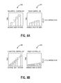
- graphs 900 , 902 , 904 , 906 illustrate channel add time using the power controller 150 and using a sequential controller method as described herein.
- the graphs 900 , 902 show one to four ROADMs in cascade (the number in each bar in the graphs 900 , 902 being indicative of the number of ROADMs in cascade).
- the graph 900 is for the sequential controller method, and the graph 902 is using the power controller 150 described herein. Further, the units are the same on the graphs 900 , 902 .
- the sequential controller method scales linearly in time based on the number of ROADMs.
- the graphs 904 , 906 show one to eight ROADMs in cascade (the number in each bar in the graphs 904 , 906 being indicative of the number of ROADMs in cascade).
- the graph 904 is for the sequential controller method, and the graph 906 is using the power controller 150 described herein. Further, the units are the same on the graphs 904 , 906 .
- the graphs 904 , 906 show similar results as the graphs 900 , 902 . In short, the timing improves by a factor of two with the power controller 150 for four ROADM sections, and for eight cascaded ROADM sections the timing improves almost by a factor of four.
- PID is one particular type of control loop and the systems and methods described herein contemplate use with any type of control loop.
- the systems and methods described herein could be applied to more general control loops including proportional-integral (PI), integral (I), and other hybrid types of linear control loops. That is, the systems and methods contemplate the various described adjustments to prevent overshooting could be applicable to any type of control loop.
- PI proportional-integral
- I integral
- other hybrid types of linear control loops that is, the systems and methods contemplate the various described adjustments to prevent overshooting could be applicable to any type of control loop.
- reference is made herein to adding a single channel using the systems and methods and those of ordinary skill in the art will recognize the systems and methods contemplate adding multiple channels concurrently and independently of one another with independent parameters using the same control loop techniques described herein.
Abstract
Description
Where:
-
- dt s refers to the pixel drive value set (e.g. via SNMP commands) in WSS iteration cycle t
- dt m refers to the measured drive or attenuation in WSS iteration cycle t that is estimated as input minus output minus the insertion loss at WSS mux port
- et m refers to the measured error in cycle t that is the delta between target power and measured power at WSS mux output
- Δt-1,t m defines the expected error change in iteration cycle t that is also same as the PID response applied in previous iteration cycle (t−1)
- Δet-1,t m refers to the measured error change between previous and current iteration cycle
- dt-1 s stands for the pixel drive value set in previous WSS iteration cycle (t−1), and
- kp, kI, kd refer to PID control coefficients
- ks, and ke core the coefficients used for considering WSS pixel drift and input power variation into account
MeasuredErr[iter]=WSSMuxOutTargetPower−WssMuxOutMeasPwr[iter]
P[iter]=Kp*MeasuredErr[iter];
I[iter]=Ki*ΣMeasuredErr[iter]*dT
I[iter]=Ki*{MeasuredErr[iter]+MeasuredErr[iter−1]+ . . . +MeasuredErr[0]}*dT
I[iter]=Ki*MeasuredErr[iter]*dT+Ki*{MeasuredErr[iter−1]+ . . . +MeasuredErr[0]}*dT
I[iter]=Ki*MeasuredErr[iter]*dT+I[iter−1];
D[iter]=Kd*(1/dT)*(MeasuredErr[iter]−MeasuredErr[iter−1]);
if (iter>0)&&(MeasuredErr[iter−1]<0), D[iter]=0.0;
Tmp — Err[iter]=P[iter]+I[iter]+D[iter];
Specifically, the measured error, MeasuredErr [iter], is computed as the difference between target output power and measured output power. The proportional value, P[iter], equals a proportional coefficient, Kp, times the measured error. The integral value, I[iter], equals an integral coefficient, Ki, times the integral of all previously measured errors. The integral value works out to equal the integral coefficient times the measured error, MeasuredErr [iter], times dT plus the previous integral value, I[iter−1]. The value dT can be a time amount related to the iteration, iter. The derivative value, D[iter], equals a derivative coefficient, Kd, times 1/dT times the difference between the measured error, MeasuredErr [iter], and the previously measured error, MeasuredErr [iter−1]. Furthermore, the derivative value, D[iter], is set to zero if the iteration is greater than zero (i.e., not the first iteration) and the previously measured error, MeasuredErr [iter−1], is less than zero. The temporary error correction value, Tmp_Err[iter] equals the proportional value, P[iter], plus the integral value, I[iter], plus the derivative value, D[iter]. In terms of notations, this temporary error correction value is:
State 1: If abs(MeasuredError[iter])>3 dB, damping_factor=1.0;
State 2: If abs(MeasuredError[iter])≦3 dB, damping_factor=0.5;
State 3: If abs(MeasuredError[iter])≦0.5 dB, Kp=0.0; Kd=0.0; damping_factor=2.5;
Tmp_Error[iter]=P[iter]+I[iter]+D[iter]; // from equation (1)
Tmp_Error[iter]=Tmp_Error[iter]*damping_factor; (2)
Expected_Error_Change[iter]=Tmp_Error[iter−1];
Meas_Error_Change[iter]=MeasuredError[iter−1]−MeasuredError[iter];
Error_Offset[iter]=abs(Expected_Error_Change[iter])−abs(Meas_Error_Change[iter]);
Error_Offset[iter]=Error_Coefficient— Ke*Error_Offset[iter]
In terms of notations,
e t offset =k e(|Δe t x |−|Δe t-1,t m|) (3)
Drive_Offset[iter]=Tmp_Error[iter]+Error_Offset[iter];
Meas_Drive[iter]=WSSMuxInput[iter]−WssMuxOutMeasPwr[iter]−WSSMuxCCT_Loss;
Set_Drive[iter]2=Meas_Drive[iter]−Drive_Offset[iter];
Prev_Set_Drive=Set_Drive[iter−1];
Current— Meas_Drive=Meas_Drive[iter];
Drive_Drift_Offset=Prev_Set_Drive−Current— Meas_Drive;
Applied_Drive_Drift_Offset=Drift_Coefficient— Ks*Drive_Drift_Offset;
if (MeasuredError[iter−1]<0)Applied_Drive_Drift_Offset=0.0;
Set_Drive[iter]=Set_Drive[iter]2+Applied_Drive_Drift_Offset;
In terms of notations,
Claims (20)
Priority Applications (2)
| Application Number | Priority Date | Filing Date | Title |
|---|---|---|---|
| US13/655,567 US9276696B2 (en) | 2012-10-19 | 2012-10-19 | Systems and methods for channel additions over multiple cascaded optical nodes |
| US15/001,359 US9973295B2 (en) | 2012-10-19 | 2016-01-20 | Systems and methods for channel additions over multiple cascaded optical nodes |
Applications Claiming Priority (1)
| Application Number | Priority Date | Filing Date | Title |
|---|---|---|---|
| US13/655,567 US9276696B2 (en) | 2012-10-19 | 2012-10-19 | Systems and methods for channel additions over multiple cascaded optical nodes |
Related Child Applications (1)
| Application Number | Title | Priority Date | Filing Date |
|---|---|---|---|
| US15/001,359 Continuation US9973295B2 (en) | 2012-10-19 | 2016-01-20 | Systems and methods for channel additions over multiple cascaded optical nodes |
Publications (2)
| Publication Number | Publication Date |
|---|---|
| US20140112660A1 US20140112660A1 (en) | 2014-04-24 |
| US9276696B2 true US9276696B2 (en) | 2016-03-01 |
Family
ID=50485432
Family Applications (2)
| Application Number | Title | Priority Date | Filing Date |
|---|---|---|---|
| US13/655,567 Active 2033-04-20 US9276696B2 (en) | 2012-10-19 | 2012-10-19 | Systems and methods for channel additions over multiple cascaded optical nodes |
| US15/001,359 Active 2032-11-01 US9973295B2 (en) | 2012-10-19 | 2016-01-20 | Systems and methods for channel additions over multiple cascaded optical nodes |
Family Applications After (1)
| Application Number | Title | Priority Date | Filing Date |
|---|---|---|---|
| US15/001,359 Active 2032-11-01 US9973295B2 (en) | 2012-10-19 | 2016-01-20 | Systems and methods for channel additions over multiple cascaded optical nodes |
Country Status (1)
| Country | Link |
|---|---|
| US (2) | US9276696B2 (en) |
Cited By (22)
| Publication number | Priority date | Publication date | Assignee | Title |
|---|---|---|---|---|
| US20150117858A1 (en) * | 2013-10-31 | 2015-04-30 | Ciena Corporation | Systems and methods for capacity changes in dwdm networks including flexible spectrum systems |
| US20160134390A1 (en) * | 2012-10-19 | 2016-05-12 | Ciena Corporation | Systems and methods for channel additions over multiple cascaded optical nodes |
| US20160315701A1 (en) * | 2015-04-24 | 2016-10-27 | Fujitsu Limited | Optical transmission device, method for verifying connection, and wavelength selective switch card |
| US9882634B1 (en) | 2016-09-20 | 2018-01-30 | Ciena Corporation | Coordinated connection validation systems and methods among mated transceivers for verifying optical and data plane connectivity |
| US9985726B1 (en) | 2016-11-29 | 2018-05-29 | Ciena Corporation | Systems and methods for a preemptive controller for photonic line systems |
| US9986317B1 (en) | 2016-11-29 | 2018-05-29 | Ciena Corporation | Systems and methods modeling optical sources in optical spectrum controllers for control thereof |
| US10050737B1 (en) * | 2017-05-04 | 2018-08-14 | Ciena Corporation | Methods and apparatus for pre-programming layer-0 service turn up speeds for photonic service provisioning or restoration |
| US10200770B2 (en) | 2017-04-07 | 2019-02-05 | Ciena Corporation | Management of flexible grid and supercarriers in optical networks using a data model |
| US10361957B1 (en) | 2018-02-09 | 2019-07-23 | Ciena Corporation | Predicting optical spectral profiles in advance of capacity changes in optical networks |
| US10439709B1 (en) | 2019-02-26 | 2019-10-08 | Ciena Corporation | Handling channel holder failures in channel holder equipped optical links |
| US10491324B2 (en) | 2017-09-29 | 2019-11-26 | Ciena Corporation | Virtualized sections for sectional control of optical links |
| US10536235B2 (en) | 2017-05-04 | 2020-01-14 | Ciena Corporation | Logical control seams in optical networks to improve restoration speed or timing for capacity adds |
| US10536236B2 (en) | 2013-08-26 | 2020-01-14 | Coriant Operations, Inc. | Intranodal ROADM fiber management apparatuses, systems, and methods |
| US10547404B1 (en) | 2018-11-13 | 2020-01-28 | Ciena Corporation | Automatic optical link calibration with channel holders |
| US10680737B1 (en) | 2019-04-09 | 2020-06-09 | Ciena Corporation | Bundling capacity changes in channel holder based optical links |
| US10686543B1 (en) | 2019-03-05 | 2020-06-16 | Ciena Corporation | Time and margin constrained routing, spectrum, and restoration speed assignment in optical networks |
| US10735837B1 (en) | 2019-07-11 | 2020-08-04 | Ciena Corporation | Partial activation of a media channel on channel holder-based optical links |
| US10833791B1 (en) | 2019-06-17 | 2020-11-10 | Ciena Corporation | Reducing interference from channel holders in an optical link |
| US10868614B2 (en) | 2018-09-04 | 2020-12-15 | Ciena Corporation | Optical power replacement for faulted spectrum in channel holder based optical links |
| US10897321B1 (en) | 2019-11-27 | 2021-01-19 | Ciena Corporation | Protection for a degree-to-degree fiber link in an optical add/drop multiplexer (OADM) |
| US11057690B2 (en) | 2019-11-14 | 2021-07-06 | Ciena Corporation | Spectrum assignments for application throughout an optical network element in a flexible-channel configuration |
| US11811459B1 (en) | 2022-07-19 | 2023-11-07 | Ciena Corporation | In-service characterization of nonlinear interference on a per-span basis |
Families Citing this family (40)
| Publication number | Priority date | Publication date | Assignee | Title |
|---|---|---|---|---|
| JP6485189B2 (en) * | 2015-04-23 | 2019-03-20 | 富士通株式会社 | Optical transmission system and optical transmission device |
| US9774392B2 (en) | 2015-07-17 | 2017-09-26 | Ciena Corporation | Systems and methods using a polarimeter to localize state of polarization transients on optical fibers |
| US9906294B2 (en) | 2015-09-23 | 2018-02-27 | Ciena Corporation | Systems and methods improving optical restoration time in networks |
| US9768902B2 (en) * | 2015-10-22 | 2017-09-19 | Ciena Corporation | Control systems and methods for spectrally overlapped flexible grid spectrum using a control bandwidth |
| US9806801B2 (en) | 2015-11-03 | 2017-10-31 | Ciena Corporation | In-service optical fault isolation systems and methods |
| US9806803B2 (en) | 2016-03-25 | 2017-10-31 | Ciena Corporation | Frequency offset detection and correction in optical spectrum measurement systems |
| US10161798B2 (en) | 2016-06-09 | 2018-12-25 | Ciena Corporation | Integrated polarimeter in an optical line system |
| US10397672B2 (en) * | 2016-06-20 | 2019-08-27 | Cable Television Laboratories, Inc. | Systems and methods for intelligent edge to edge optical system and wavelength provisioning |
| US10200123B2 (en) | 2016-06-20 | 2019-02-05 | Cable Television Laboratories, Inc. | System and methods for distribution of heterogeneous wavelength multiplexed signals over optical access network |
| US10784979B2 (en) * | 2017-03-15 | 2020-09-22 | Huawei Technologies Co., Ltd. | System and method of providing dark section free transport networks |
| US10439751B2 (en) | 2017-05-24 | 2019-10-08 | Ciena Corporation | Power control in an optical fiber network |
| WO2018215850A1 (en) * | 2017-05-24 | 2018-11-29 | Ciena Corporation | Adjustment of control parameters of section of optical fiber network and power control in an optical fiber network |
| US10142022B1 (en) | 2017-05-24 | 2018-11-27 | Ciena Corporation | Adjustment of control parameters of section of optical fiber network |
| US11374675B2 (en) * | 2017-06-28 | 2022-06-28 | Huawei Technologies Co., Ltd. | Method and apparatus for modifying channels in an optical medium |
| CN110120839B (en) * | 2018-02-07 | 2021-11-02 | 中兴通讯股份有限公司 | Method and device for controlling WSS channel attenuation, storage medium and processor |
| US10560212B2 (en) | 2018-05-21 | 2020-02-11 | Ciena Corporation | Systems and methods for mesh restoration in networks due to intra-node faults |
| US11139633B2 (en) | 2019-03-27 | 2021-10-05 | Ciena Corporation | In-situ fiber characterization using nonlinear skirt measurement |
| US11799546B2 (en) | 2019-03-27 | 2023-10-24 | Ciena Corporation | Optical fiber characterization using a nonlinear skirt measurement |
| US10797818B1 (en) * | 2019-07-15 | 2020-10-06 | Ciena Corporation | Dynamic data-driven power scaling in an optical node and network |
| CN111027542A (en) * | 2019-11-20 | 2020-04-17 | 天津大学 | Target detection method improved based on fast RCNN algorithm |
| US10965373B1 (en) | 2020-01-06 | 2021-03-30 | Ciena Corporation | Handling band spectrum failures in a C+L band photonic line system |
| US10826641B1 (en) | 2020-02-12 | 2020-11-03 | Ciena Corporation | Swapping bundles of optical channels in a C+L band system based on frequency band sensitivity |
| US11063683B1 (en) | 2020-06-12 | 2021-07-13 | Ciena Corporation | Scalable ROADM architecture with multi-plane switching |
| US10985838B1 (en) | 2020-08-13 | 2021-04-20 | Ciena Corporation | Handling compensation for losses in optical fiber links |
| US11569907B2 (en) | 2020-08-26 | 2023-01-31 | Ciena Corporation | Per-band fault signaling in a multi-band optical transmission system |
| US11108489B1 (en) | 2020-09-30 | 2021-08-31 | Ciena Corporation | Reducing connection validation (CV) time in an optical node |
| US11196504B1 (en) | 2020-10-28 | 2021-12-07 | Ciena Corporation | Extending the optical spectrum of an optical network |
| US11553259B2 (en) | 2020-10-28 | 2023-01-10 | Ciena Corporation | Extending the optical spectrum of an optical network |
| US11652545B2 (en) | 2020-11-24 | 2023-05-16 | Ciena Corporation | Avoiding fiber damage on non-supervisory optical fiber links |
| US11223423B1 (en) | 2020-12-22 | 2022-01-11 | Ciena Corporation | Re-calibrating an in-service optical multiplex section (OMS) |
| US11502746B2 (en) | 2020-12-28 | 2022-11-15 | Ciena Corporation | Power optimization of point-to-point optical systems without visibility of intermediate system parameters |
| US11658452B2 (en) | 2021-02-11 | 2023-05-23 | Ciena Corporation | Powering up an optical amplifier in an optical line system |
| US11272269B1 (en) | 2021-03-29 | 2022-03-08 | Ciena Corporation | Integrated band splitter for scaling dual-band ROADM |
| US11695474B2 (en) | 2021-04-07 | 2023-07-04 | Ciena Corporation | Autonomous provisioning of optical channels in submarine or foreign optical line systems |
| US11770193B2 (en) * | 2021-07-28 | 2023-09-26 | Ciena Corporation | Mitigating instability in cascaded optical power controllers |
| US11824581B2 (en) | 2021-08-11 | 2023-11-21 | Ciena Corporation | Turn-up procedure for local and remote amplifiers in an optical system |
| US11553262B1 (en) | 2021-10-21 | 2023-01-10 | Ciena Corporation | Resolving control conflicts among trunk protection links |
| US11916590B2 (en) | 2021-11-24 | 2024-02-27 | Ciena Corporation | Distributed in-service spectrum power compensation |
| US11637635B1 (en) | 2021-12-07 | 2023-04-25 | Ciena Corporation | Calibrating a Raman amplifier by maximizing gain and minimizing intermodulation effects |
| US11870488B2 (en) | 2022-02-25 | 2024-01-09 | Ciena Corporation | Fast fiber transient locating systems and methods |
Citations (24)
| Publication number | Priority date | Publication date | Assignee | Title |
|---|---|---|---|---|
| US5442544A (en) * | 1990-01-26 | 1995-08-15 | Honeywell Inc. | Single input single output rate optimal controller |
| US20030058497A1 (en) * | 2001-09-27 | 2003-03-27 | Nortel Networks Limited | All-optical switching sites for an agile optical network |
| US20060018658A1 (en) * | 2004-07-20 | 2006-01-26 | Shota Mori | Wavelength division multiplexing optical transmission system |
| US20070269215A1 (en) * | 2006-05-19 | 2007-11-22 | Fujitsu Limited | Wavelength-division-multiplexing optical transmission system and control method thereof |
| US7444078B1 (en) * | 2003-09-18 | 2008-10-28 | At&T Intellectual Property Ii, L.P. | Transient control solution for optical networks |
| US20080285973A1 (en) * | 2007-05-16 | 2008-11-20 | Yasuhiro Uchiyama | Optical add/drop multiplexer |
| US20090116837A1 (en) | 2006-04-27 | 2009-05-07 | Nortel Networks Limited | Method and system for controlling optical networks |
| US20100091355A1 (en) | 2007-02-26 | 2010-04-15 | Takeshi Ota | Optical fiber transport devices and optical communication networks |
| US20100104276A1 (en) * | 2007-07-03 | 2010-04-29 | Fujitsu Limited | Level decline detecting apparatus, optical amplifier apparatus, and level decline detecting method |
| US20100202777A1 (en) | 2009-02-06 | 2010-08-12 | Qingyun Liu | Mechanism to dectect an unstable wavelength channel and limit its impact on a ROADM network |
| US20100221004A1 (en) | 2009-02-27 | 2010-09-02 | Thomas Haslam | Method for auto-configuration of a wavelength selective switch in an optical network |
| US7826748B2 (en) | 2007-03-23 | 2010-11-02 | Ciena Corporation | Systems and methods for adaptive gain control to compensate OSNR penalty caused by side-lobe of MEMS-based reconfigurable optical add-drop multiplexers |
| US7873274B2 (en) * | 2007-04-10 | 2011-01-18 | Ciena Corporation | Methods and systems to stabilize an optical network against nodal gain changes |
| US7983560B2 (en) | 2005-10-11 | 2011-07-19 | Dynamic Method Enterprises Limited | Modular WSS-based communications system with colorless add/drop interfaces |
| US20110176802A1 (en) * | 2008-07-28 | 2011-07-21 | Paul Alexander Callan | Channel Power Control in an Optical Network Node |
| US20110200324A1 (en) | 2010-02-16 | 2011-08-18 | Ciena Corporation | Method and system for optical connection validation |
| US20110222862A1 (en) | 2010-03-12 | 2011-09-15 | Ciena Corporation | Make before break optical mesh network element |
| US20110222851A1 (en) | 2010-03-12 | 2011-09-15 | Nortel Networks Limited | Method to transform a dynamic analog optical network to a digital representation |
| US20110222846A1 (en) | 2010-03-12 | 2011-09-15 | Ciena Corporation | Shared photonic mesh |
| US20110268442A1 (en) | 2008-10-17 | 2011-11-03 | Ciena Corporation | Coherent augmented optical add-drop multiplexer |
| US20110274425A1 (en) | 2010-05-07 | 2011-11-10 | Klaus Grobe | Method for providing protection in an optical communication network against connection failures |
| US8077384B2 (en) * | 2007-07-27 | 2011-12-13 | Fujitsu Limited | Optical amplifier, and optical transmission system including the optical amplifier |
| US8095008B2 (en) * | 2007-04-25 | 2012-01-10 | Ciena Corporation | Systems and methods for a multiple-input, multiple-output controller in a reconfigurable optical network |
| US8135280B2 (en) * | 2007-10-08 | 2012-03-13 | Nec Laboratories America, Inc. | Method and system for power stability control in wavelength division multiplexing networks |
Family Cites Families (6)
| Publication number | Priority date | Publication date | Assignee | Title |
|---|---|---|---|---|
| US7058301B2 (en) * | 2002-02-28 | 2006-06-06 | Bosloy Jonathan L | Apparatus and method for planned wavelength addition and removal in a wavelength division multiplexed system |
| US6668137B1 (en) * | 2002-06-26 | 2003-12-23 | Nortel Networks Limited | Feed forward optical power control |
| US20040208577A1 (en) * | 2002-07-23 | 2004-10-21 | Sycamore Networks, Inc. | Methods for in-service wavelength upgrade and system performance optimization in WDM optical networks |
| US8855500B2 (en) * | 2008-10-03 | 2014-10-07 | Telefonaktiebolaget Lm Ericsson | Channel power control in an optical link |
| CN103095370B (en) * | 2011-11-03 | 2016-05-18 | 华为技术有限公司 | Method and the controller of wavelength division multiplexed optical network dilatation commissioning |
| US9276696B2 (en) * | 2012-10-19 | 2016-03-01 | Ciena Corporation | Systems and methods for channel additions over multiple cascaded optical nodes |
-
2012
- 2012-10-19 US US13/655,567 patent/US9276696B2/en active Active
-
2016
- 2016-01-20 US US15/001,359 patent/US9973295B2/en active Active
Patent Citations (25)
| Publication number | Priority date | Publication date | Assignee | Title |
|---|---|---|---|---|
| US5442544A (en) * | 1990-01-26 | 1995-08-15 | Honeywell Inc. | Single input single output rate optimal controller |
| US20030058497A1 (en) * | 2001-09-27 | 2003-03-27 | Nortel Networks Limited | All-optical switching sites for an agile optical network |
| US7444078B1 (en) * | 2003-09-18 | 2008-10-28 | At&T Intellectual Property Ii, L.P. | Transient control solution for optical networks |
| US20060018658A1 (en) * | 2004-07-20 | 2006-01-26 | Shota Mori | Wavelength division multiplexing optical transmission system |
| US7983560B2 (en) | 2005-10-11 | 2011-07-19 | Dynamic Method Enterprises Limited | Modular WSS-based communications system with colorless add/drop interfaces |
| US20090116837A1 (en) | 2006-04-27 | 2009-05-07 | Nortel Networks Limited | Method and system for controlling optical networks |
| US20070269215A1 (en) * | 2006-05-19 | 2007-11-22 | Fujitsu Limited | Wavelength-division-multiplexing optical transmission system and control method thereof |
| US20100091355A1 (en) | 2007-02-26 | 2010-04-15 | Takeshi Ota | Optical fiber transport devices and optical communication networks |
| US7826748B2 (en) | 2007-03-23 | 2010-11-02 | Ciena Corporation | Systems and methods for adaptive gain control to compensate OSNR penalty caused by side-lobe of MEMS-based reconfigurable optical add-drop multiplexers |
| US7873274B2 (en) * | 2007-04-10 | 2011-01-18 | Ciena Corporation | Methods and systems to stabilize an optical network against nodal gain changes |
| US8160446B2 (en) | 2007-04-10 | 2012-04-17 | Ciena Corporation | Methods and systems to stabilize an optical network against nodal gain changes |
| US8095008B2 (en) * | 2007-04-25 | 2012-01-10 | Ciena Corporation | Systems and methods for a multiple-input, multiple-output controller in a reconfigurable optical network |
| US20080285973A1 (en) * | 2007-05-16 | 2008-11-20 | Yasuhiro Uchiyama | Optical add/drop multiplexer |
| US20100104276A1 (en) * | 2007-07-03 | 2010-04-29 | Fujitsu Limited | Level decline detecting apparatus, optical amplifier apparatus, and level decline detecting method |
| US8077384B2 (en) * | 2007-07-27 | 2011-12-13 | Fujitsu Limited | Optical amplifier, and optical transmission system including the optical amplifier |
| US8135280B2 (en) * | 2007-10-08 | 2012-03-13 | Nec Laboratories America, Inc. | Method and system for power stability control in wavelength division multiplexing networks |
| US20110176802A1 (en) * | 2008-07-28 | 2011-07-21 | Paul Alexander Callan | Channel Power Control in an Optical Network Node |
| US20110268442A1 (en) | 2008-10-17 | 2011-11-03 | Ciena Corporation | Coherent augmented optical add-drop multiplexer |
| US20100202777A1 (en) | 2009-02-06 | 2010-08-12 | Qingyun Liu | Mechanism to dectect an unstable wavelength channel and limit its impact on a ROADM network |
| US20100221004A1 (en) | 2009-02-27 | 2010-09-02 | Thomas Haslam | Method for auto-configuration of a wavelength selective switch in an optical network |
| US20110200324A1 (en) | 2010-02-16 | 2011-08-18 | Ciena Corporation | Method and system for optical connection validation |
| US20110222846A1 (en) | 2010-03-12 | 2011-09-15 | Ciena Corporation | Shared photonic mesh |
| US20110222851A1 (en) | 2010-03-12 | 2011-09-15 | Nortel Networks Limited | Method to transform a dynamic analog optical network to a digital representation |
| US20110222862A1 (en) | 2010-03-12 | 2011-09-15 | Ciena Corporation | Make before break optical mesh network element |
| US20110274425A1 (en) | 2010-05-07 | 2011-11-10 | Klaus Grobe | Method for providing protection in an optical communication network against connection failures |
Non-Patent Citations (2)
| Title |
|---|
| Aggarwal et al., A Self-Tuning Analog Proportional-Integral-Derivative (PID) Controller, 2006, IEEE. * |
| PID Theory Explained, Mar. 29, 2011. * |
Cited By (32)
| Publication number | Priority date | Publication date | Assignee | Title |
|---|---|---|---|---|
| US20160134390A1 (en) * | 2012-10-19 | 2016-05-12 | Ciena Corporation | Systems and methods for channel additions over multiple cascaded optical nodes |
| US9973295B2 (en) * | 2012-10-19 | 2018-05-15 | Ciena Corporation | Systems and methods for channel additions over multiple cascaded optical nodes |
| US10536236B2 (en) | 2013-08-26 | 2020-01-14 | Coriant Operations, Inc. | Intranodal ROADM fiber management apparatuses, systems, and methods |
| US9344191B2 (en) * | 2013-10-31 | 2016-05-17 | Ciena Corporation | Systems and methods for capacity changes in DWDM networks including flexible spectrum systems |
| US20150117858A1 (en) * | 2013-10-31 | 2015-04-30 | Ciena Corporation | Systems and methods for capacity changes in dwdm networks including flexible spectrum systems |
| US20160315701A1 (en) * | 2015-04-24 | 2016-10-27 | Fujitsu Limited | Optical transmission device, method for verifying connection, and wavelength selective switch card |
| US9882634B1 (en) | 2016-09-20 | 2018-01-30 | Ciena Corporation | Coordinated connection validation systems and methods among mated transceivers for verifying optical and data plane connectivity |
| US9985726B1 (en) | 2016-11-29 | 2018-05-29 | Ciena Corporation | Systems and methods for a preemptive controller for photonic line systems |
| US9986317B1 (en) | 2016-11-29 | 2018-05-29 | Ciena Corporation | Systems and methods modeling optical sources in optical spectrum controllers for control thereof |
| US10958993B2 (en) | 2017-04-07 | 2021-03-23 | Ciena Corporation | Management of flexible grid and supercarriers in optical networks using a data model |
| US10455300B2 (en) | 2017-04-07 | 2019-10-22 | Ciena Corporation | Management of flexible grid and supercarriers in optical networks using a data model |
| US10200770B2 (en) | 2017-04-07 | 2019-02-05 | Ciena Corporation | Management of flexible grid and supercarriers in optical networks using a data model |
| US10237011B2 (en) * | 2017-05-04 | 2019-03-19 | Ciena Corporation | Methods and apparatus for pre-programming layer-0 service turn up speeds for photonic service provisioning or restoration |
| US10536235B2 (en) | 2017-05-04 | 2020-01-14 | Ciena Corporation | Logical control seams in optical networks to improve restoration speed or timing for capacity adds |
| US10050737B1 (en) * | 2017-05-04 | 2018-08-14 | Ciena Corporation | Methods and apparatus for pre-programming layer-0 service turn up speeds for photonic service provisioning or restoration |
| US11444719B2 (en) | 2017-09-29 | 2022-09-13 | Ciena Corporation | Virtualized sections for sectional control of optical links |
| US10491324B2 (en) | 2017-09-29 | 2019-11-26 | Ciena Corporation | Virtualized sections for sectional control of optical links |
| US11057146B2 (en) * | 2017-09-29 | 2021-07-06 | Ciena Corporation | Virtualized sections for sectional control of optical links |
| US10361957B1 (en) | 2018-02-09 | 2019-07-23 | Ciena Corporation | Predicting optical spectral profiles in advance of capacity changes in optical networks |
| US10868614B2 (en) | 2018-09-04 | 2020-12-15 | Ciena Corporation | Optical power replacement for faulted spectrum in channel holder based optical links |
| US11456814B2 (en) | 2018-11-13 | 2022-09-27 | Ciena Corporation | Automatic optical link calibration with channel holders |
| US11784738B2 (en) | 2018-11-13 | 2023-10-10 | Ciena Corporation | Differentiating traffic signals from filler channels in optical networks and band augmentation |
| US10547404B1 (en) | 2018-11-13 | 2020-01-28 | Ciena Corporation | Automatic optical link calibration with channel holders |
| US10439709B1 (en) | 2019-02-26 | 2019-10-08 | Ciena Corporation | Handling channel holder failures in channel holder equipped optical links |
| US10686543B1 (en) | 2019-03-05 | 2020-06-16 | Ciena Corporation | Time and margin constrained routing, spectrum, and restoration speed assignment in optical networks |
| US10680737B1 (en) | 2019-04-09 | 2020-06-09 | Ciena Corporation | Bundling capacity changes in channel holder based optical links |
| US11777634B2 (en) | 2019-04-09 | 2023-10-03 | Ciena Corporation | Bundling capacity changes in channel holder based optical links |
| US10833791B1 (en) | 2019-06-17 | 2020-11-10 | Ciena Corporation | Reducing interference from channel holders in an optical link |
| US10735837B1 (en) | 2019-07-11 | 2020-08-04 | Ciena Corporation | Partial activation of a media channel on channel holder-based optical links |
| US11057690B2 (en) | 2019-11-14 | 2021-07-06 | Ciena Corporation | Spectrum assignments for application throughout an optical network element in a flexible-channel configuration |
| US10897321B1 (en) | 2019-11-27 | 2021-01-19 | Ciena Corporation | Protection for a degree-to-degree fiber link in an optical add/drop multiplexer (OADM) |
| US11811459B1 (en) | 2022-07-19 | 2023-11-07 | Ciena Corporation | In-service characterization of nonlinear interference on a per-span basis |
Also Published As
| Publication number | Publication date |
|---|---|
| US9973295B2 (en) | 2018-05-15 |
| US20140112660A1 (en) | 2014-04-24 |
| US20160134390A1 (en) | 2016-05-12 |
Similar Documents
| Publication | Publication Date | Title |
|---|---|---|
| US9973295B2 (en) | Systems and methods for channel additions over multiple cascaded optical nodes | |
| US9985726B1 (en) | Systems and methods for a preemptive controller for photonic line systems | |
| US10536235B2 (en) | Logical control seams in optical networks to improve restoration speed or timing for capacity adds | |
| US9344191B2 (en) | Systems and methods for capacity changes in DWDM networks including flexible spectrum systems | |
| US10237011B2 (en) | Methods and apparatus for pre-programming layer-0 service turn up speeds for photonic service provisioning or restoration | |
| TWI719486B (en) | Open, modular, and scalable optical line system | |
| US20160315711A1 (en) | Spectrum controller systems and methods in optical networks | |
| US10361957B1 (en) | Predicting optical spectral profiles in advance of capacity changes in optical networks | |
| US9768902B2 (en) | Control systems and methods for spectrally overlapped flexible grid spectrum using a control bandwidth | |
| EP2319202B1 (en) | Channel power control in an optical network node | |
| US9917642B2 (en) | Method and apparatus for establishing a communication path in an optical network | |
| CN102598707B (en) | Method for balancing links performance and device for the same | |
| CN112585889B (en) | Method and device for establishing data model | |
| US20040052526A1 (en) | Connection optimization and control in agile networks | |
| WO2019196884A1 (en) | System and method for optical channel reconfiguration | |
| US11770193B2 (en) | Mitigating instability in cascaded optical power controllers | |
| US8855500B2 (en) | Channel power control in an optical link | |
| US20180138973A1 (en) | Network management device and network management method | |
| Kilper et al. | Amplifier issues for physical layer network control | |
| US11902724B2 (en) | Resolving control conflicts among trunk protection links | |
| BR102014029519B1 (en) | Arrangement and method for cascaded and distributed dynamic equalization of optical channels |
Legal Events
| Date | Code | Title | Description |
|---|---|---|---|
| AS | Assignment |
Owner name: CIENA CORPORATION, MARYLAND Free format text: ASSIGNMENT OF ASSIGNORS INTEREST;ASSIGNORS:AL SAYEED, CHOUDHURY A.;BOWNASS, DAVID C.;BERG, LOREN S.;AND OTHERS;SIGNING DATES FROM 20121017 TO 20121019;REEL/FRAME:029157/0286 |
|
| AS | Assignment |
Owner name: DEUTSCHE BANK AG NEW YORK BRANCH, NEW YORK Free format text: SECURITY INTEREST;ASSIGNOR:CIENA CORPORATION;REEL/FRAME:033329/0417 Effective date: 20140715 |
|
| AS | Assignment |
Owner name: BANK OF AMERICA, N.A., AS ADMINISTRATIVE AGENT, NO Free format text: PATENT SECURITY AGREEMENT;ASSIGNOR:CIENA CORPORATION;REEL/FRAME:033347/0260 Effective date: 20140715 |
|
| FEPP | Fee payment procedure |
Free format text: PAYOR NUMBER ASSIGNED (ORIGINAL EVENT CODE: ASPN); ENTITY STATUS OF PATENT OWNER: LARGE ENTITY |
|
| STCF | Information on status: patent grant |
Free format text: PATENTED CASE |
|
| FEPP | Fee payment procedure |
Free format text: PAYER NUMBER DE-ASSIGNED (ORIGINAL EVENT CODE: RMPN); ENTITY STATUS OF PATENT OWNER: LARGE ENTITY Free format text: PAYOR NUMBER ASSIGNED (ORIGINAL EVENT CODE: ASPN); ENTITY STATUS OF PATENT OWNER: LARGE ENTITY |
|
| MAFP | Maintenance fee payment |
Free format text: PAYMENT OF MAINTENANCE FEE, 4TH YEAR, LARGE ENTITY (ORIGINAL EVENT CODE: M1551); ENTITY STATUS OF PATENT OWNER: LARGE ENTITY Year of fee payment: 4 |
|
| AS | Assignment |
Owner name: CIENA CORPORATION, MARYLAND Free format text: RELEASE BY SECURED PARTY;ASSIGNOR:DEUTSCHE BANK AG NEW YORK BRANCH;REEL/FRAME:050938/0389 Effective date: 20191028 |
|
| AS | Assignment |
Owner name: BANK OF AMERICA, N.A., AS COLLATERAL AGENT, ILLINO Free format text: PATENT SECURITY AGREEMENT;ASSIGNOR:CIENA CORPORATION;REEL/FRAME:050969/0001 Effective date: 20191028 |
|
| MAFP | Maintenance fee payment |
Free format text: PAYMENT OF MAINTENANCE FEE, 8TH YEAR, LARGE ENTITY (ORIGINAL EVENT CODE: M1552); ENTITY STATUS OF PATENT OWNER: LARGE ENTITY Year of fee payment: 8 |
|
| AS | Assignment |
Owner name: CIENA CORPORATION, MARYLAND Free format text: RELEASE BY SECURED PARTY;ASSIGNOR:BANK OF AMERICA, N.A.;REEL/FRAME:065630/0232 Effective date: 20231024 |