US9257095B2 - Display device with a backlight - Google Patents
Display device with a backlight Download PDFInfo
- Publication number
- US9257095B2 US9257095B2 US14/319,277 US201414319277A US9257095B2 US 9257095 B2 US9257095 B2 US 9257095B2 US 201414319277 A US201414319277 A US 201414319277A US 9257095 B2 US9257095 B2 US 9257095B2
- Authority
- US
- United States
- Prior art keywords
- display
- emitter
- color
- image data
- led
- Prior art date
- Legal status (The legal status is an assumption and is not a legal conclusion. Google has not performed a legal analysis and makes no representation as to the accuracy of the status listed.)
- Expired - Fee Related, expires
Links
- 239000003086 colorant Substances 0.000 claims abstract description 44
- 238000001228 spectrum Methods 0.000 claims abstract description 24
- 239000004973 liquid crystal related substance Substances 0.000 claims abstract description 23
- 238000005286 illumination Methods 0.000 claims abstract description 11
- 238000009877 rendering Methods 0.000 claims abstract description 5
- 238000000034 method Methods 0.000 claims description 11
- 238000006243 chemical reaction Methods 0.000 claims description 8
- 230000009021 linear effect Effects 0.000 claims description 8
- 238000004364 calculation method Methods 0.000 claims description 6
- 230000009466 transformation Effects 0.000 claims description 6
- 230000008569 process Effects 0.000 claims description 5
- 230000008859 change Effects 0.000 claims description 3
- 230000004048 modification Effects 0.000 claims description 3
- 238000012986 modification Methods 0.000 claims description 3
- 230000005540 biological transmission Effects 0.000 description 59
- 239000011159 matrix material Substances 0.000 description 14
- 230000003595 spectral effect Effects 0.000 description 13
- 229920006395 saturated elastomer Polymers 0.000 description 9
- 238000013459 approach Methods 0.000 description 8
- 238000010586 diagram Methods 0.000 description 6
- 230000008901 benefit Effects 0.000 description 5
- 238000012545 processing Methods 0.000 description 5
- 239000000758 substrate Substances 0.000 description 5
- 239000011521 glass Substances 0.000 description 4
- 238000010191 image analysis Methods 0.000 description 4
- 239000010408 film Substances 0.000 description 3
- 230000006870 function Effects 0.000 description 3
- 230000001419 dependent effect Effects 0.000 description 2
- 239000000203 mixture Substances 0.000 description 2
- 230000003287 optical effect Effects 0.000 description 2
- 239000013589 supplement Substances 0.000 description 2
- 230000004075 alteration Effects 0.000 description 1
- 238000004458 analytical method Methods 0.000 description 1
- 230000000712 assembly Effects 0.000 description 1
- 238000000429 assembly Methods 0.000 description 1
- 239000002131 composite material Substances 0.000 description 1
- 238000013461 design Methods 0.000 description 1
- 238000011161 development Methods 0.000 description 1
- 230000018109 developmental process Effects 0.000 description 1
- 238000000295 emission spectrum Methods 0.000 description 1
- 230000006872 improvement Effects 0.000 description 1
- 238000009828 non-uniform distribution Methods 0.000 description 1
- 230000009022 nonlinear effect Effects 0.000 description 1
- 238000010561 standard procedure Methods 0.000 description 1
- 239000010409 thin film Substances 0.000 description 1
- 238000002834 transmittance Methods 0.000 description 1
Images


Classifications
-
- G—PHYSICS
- G09—EDUCATION; CRYPTOGRAPHY; DISPLAY; ADVERTISING; SEALS
- G09G—ARRANGEMENTS OR CIRCUITS FOR CONTROL OF INDICATING DEVICES USING STATIC MEANS TO PRESENT VARIABLE INFORMATION
- G09G5/00—Control arrangements or circuits for visual indicators common to cathode-ray tube indicators and other visual indicators
- G09G5/10—Intensity circuits
-
- G—PHYSICS
- G02—OPTICS
- G02F—OPTICAL DEVICES OR ARRANGEMENTS FOR THE CONTROL OF LIGHT BY MODIFICATION OF THE OPTICAL PROPERTIES OF THE MEDIA OF THE ELEMENTS INVOLVED THEREIN; NON-LINEAR OPTICS; FREQUENCY-CHANGING OF LIGHT; OPTICAL LOGIC ELEMENTS; OPTICAL ANALOGUE/DIGITAL CONVERTERS
- G02F1/00—Devices or arrangements for the control of the intensity, colour, phase, polarisation or direction of light arriving from an independent light source, e.g. switching, gating or modulating; Non-linear optics
- G02F1/01—Devices or arrangements for the control of the intensity, colour, phase, polarisation or direction of light arriving from an independent light source, e.g. switching, gating or modulating; Non-linear optics for the control of the intensity, phase, polarisation or colour
- G02F1/13—Devices or arrangements for the control of the intensity, colour, phase, polarisation or direction of light arriving from an independent light source, e.g. switching, gating or modulating; Non-linear optics for the control of the intensity, phase, polarisation or colour based on liquid crystals, e.g. single liquid crystal display cells
- G02F1/133—Constructional arrangements; Operation of liquid crystal cells; Circuit arrangements
- G02F1/1333—Constructional arrangements; Manufacturing methods
- G02F1/1335—Structural association of cells with optical devices, e.g. polarisers or reflectors
- G02F1/133509—Filters, e.g. light shielding masks
- G02F1/133514—Colour filters
-
- G—PHYSICS
- G02—OPTICS
- G02F—OPTICAL DEVICES OR ARRANGEMENTS FOR THE CONTROL OF LIGHT BY MODIFICATION OF THE OPTICAL PROPERTIES OF THE MEDIA OF THE ELEMENTS INVOLVED THEREIN; NON-LINEAR OPTICS; FREQUENCY-CHANGING OF LIGHT; OPTICAL LOGIC ELEMENTS; OPTICAL ANALOGUE/DIGITAL CONVERTERS
- G02F1/00—Devices or arrangements for the control of the intensity, colour, phase, polarisation or direction of light arriving from an independent light source, e.g. switching, gating or modulating; Non-linear optics
- G02F1/01—Devices or arrangements for the control of the intensity, colour, phase, polarisation or direction of light arriving from an independent light source, e.g. switching, gating or modulating; Non-linear optics for the control of the intensity, phase, polarisation or colour
- G02F1/13—Devices or arrangements for the control of the intensity, colour, phase, polarisation or direction of light arriving from an independent light source, e.g. switching, gating or modulating; Non-linear optics for the control of the intensity, phase, polarisation or colour based on liquid crystals, e.g. single liquid crystal display cells
- G02F1/133—Constructional arrangements; Operation of liquid crystal cells; Circuit arrangements
- G02F1/1333—Constructional arrangements; Manufacturing methods
- G02F1/1335—Structural association of cells with optical devices, e.g. polarisers or reflectors
- G02F1/1336—Illuminating devices
- G02F1/133602—Direct backlight
- G02F1/133603—Direct backlight with LEDs
-
- G—PHYSICS
- G09—EDUCATION; CRYPTOGRAPHY; DISPLAY; ADVERTISING; SEALS
- G09G—ARRANGEMENTS OR CIRCUITS FOR CONTROL OF INDICATING DEVICES USING STATIC MEANS TO PRESENT VARIABLE INFORMATION
- G09G3/00—Control arrangements or circuits, of interest only in connection with visual indicators other than cathode-ray tubes
- G09G3/20—Control arrangements or circuits, of interest only in connection with visual indicators other than cathode-ray tubes for presentation of an assembly of a number of characters, e.g. a page, by composing the assembly by combination of individual elements arranged in a matrix no fixed position being assigned to or needed to be assigned to the individual characters or partial characters
- G09G3/34—Control arrangements or circuits, of interest only in connection with visual indicators other than cathode-ray tubes for presentation of an assembly of a number of characters, e.g. a page, by composing the assembly by combination of individual elements arranged in a matrix no fixed position being assigned to or needed to be assigned to the individual characters or partial characters by control of light from an independent source
- G09G3/3406—Control of illumination source
- G09G3/3413—Details of control of colour illumination sources
-
- G—PHYSICS
- G09—EDUCATION; CRYPTOGRAPHY; DISPLAY; ADVERTISING; SEALS
- G09G—ARRANGEMENTS OR CIRCUITS FOR CONTROL OF INDICATING DEVICES USING STATIC MEANS TO PRESENT VARIABLE INFORMATION
- G09G3/00—Control arrangements or circuits, of interest only in connection with visual indicators other than cathode-ray tubes
- G09G3/20—Control arrangements or circuits, of interest only in connection with visual indicators other than cathode-ray tubes for presentation of an assembly of a number of characters, e.g. a page, by composing the assembly by combination of individual elements arranged in a matrix no fixed position being assigned to or needed to be assigned to the individual characters or partial characters
- G09G3/34—Control arrangements or circuits, of interest only in connection with visual indicators other than cathode-ray tubes for presentation of an assembly of a number of characters, e.g. a page, by composing the assembly by combination of individual elements arranged in a matrix no fixed position being assigned to or needed to be assigned to the individual characters or partial characters by control of light from an independent source
- G09G3/36—Control arrangements or circuits, of interest only in connection with visual indicators other than cathode-ray tubes for presentation of an assembly of a number of characters, e.g. a page, by composing the assembly by combination of individual elements arranged in a matrix no fixed position being assigned to or needed to be assigned to the individual characters or partial characters by control of light from an independent source using liquid crystals
- G09G3/3611—Control of matrices with row and column drivers
- G09G3/3696—Generation of voltages supplied to electrode drivers
-
- G—PHYSICS
- G09—EDUCATION; CRYPTOGRAPHY; DISPLAY; ADVERTISING; SEALS
- G09G—ARRANGEMENTS OR CIRCUITS FOR CONTROL OF INDICATING DEVICES USING STATIC MEANS TO PRESENT VARIABLE INFORMATION
- G09G5/00—Control arrangements or circuits for visual indicators common to cathode-ray tube indicators and other visual indicators
- G09G5/02—Control arrangements or circuits for visual indicators common to cathode-ray tube indicators and other visual indicators characterised by the way in which colour is displayed
-
- G—PHYSICS
- G09—EDUCATION; CRYPTOGRAPHY; DISPLAY; ADVERTISING; SEALS
- G09G—ARRANGEMENTS OR CIRCUITS FOR CONTROL OF INDICATING DEVICES USING STATIC MEANS TO PRESENT VARIABLE INFORMATION
- G09G5/00—Control arrangements or circuits for visual indicators common to cathode-ray tube indicators and other visual indicators
- G09G5/18—Timing circuits for raster scan displays
-
- G—PHYSICS
- G09—EDUCATION; CRYPTOGRAPHY; DISPLAY; ADVERTISING; SEALS
- G09G—ARRANGEMENTS OR CIRCUITS FOR CONTROL OF INDICATING DEVICES USING STATIC MEANS TO PRESENT VARIABLE INFORMATION
- G09G2310/00—Command of the display device
- G09G2310/02—Addressing, scanning or driving the display screen or processing steps related thereto
- G09G2310/0235—Field-sequential colour display
-
- G—PHYSICS
- G09—EDUCATION; CRYPTOGRAPHY; DISPLAY; ADVERTISING; SEALS
- G09G—ARRANGEMENTS OR CIRCUITS FOR CONTROL OF INDICATING DEVICES USING STATIC MEANS TO PRESENT VARIABLE INFORMATION
- G09G2330/00—Aspects of power supply; Aspects of display protection and defect management
- G09G2330/02—Details of power systems and of start or stop of display operation
- G09G2330/021—Power management, e.g. power saving
-
- G—PHYSICS
- G09—EDUCATION; CRYPTOGRAPHY; DISPLAY; ADVERTISING; SEALS
- G09G—ARRANGEMENTS OR CIRCUITS FOR CONTROL OF INDICATING DEVICES USING STATIC MEANS TO PRESENT VARIABLE INFORMATION
- G09G2340/00—Aspects of display data processing
- G09G2340/06—Colour space transformation
Definitions
- the invention relates to a display device and, more particularly, to a display device comprising a combination of backlight emitters, and a means of selectively powering each backlight at different levels, and a means of modifying the image data input to the display so as to maintain correct color appearance under the different possible backlight emitter levels.
- an image is produced by controlling the light transmittance of a two-dimensional array of discrete image elements (subpixels). Control is performed by the conversion of digital image data, consisting of a data value for each subpixel of the image, into analogue voltages with values dependent on that data, and direction of those voltages to each pixel electrode in the array via an active matrix of source data lines, gate lines and thin film transistor (TFT) switching elements.
- digital image data consisting of a data value for each subpixel of the image
- TFT thin film transistor
- a block of three subpixels is termed a pixel.
- Each subpixel is associated with a color filter (typically Red, Green and Blue), and by controlling the amount of light being transmitted through these three color channels, any resultant linear combination of Red, Green and Blue light can be produced.
- a color filter typically Red, Green and Blue
- the color is said to be “saturated” in that the color is as vivid as is possible with this display.
- Some LCDs are capable of producing very vivid saturated colors, while some are only able to produce pale colors, even with only one color channel in the on state.
- the vividness of the color is related to its light spectrum. A light with a very broad spectrum will appear pale, while a narrow spectral light will appear vivid.
- a monochromatic light that is, light with only one wavelength, typically produced by a laser is the most vivid light possible.
- each color filter will only transmit a particular range of wavelengths.
- a narrow range will produce more vivid colors, but since more light is being absorbed by the filter, the brightness of the screen is reduced.
- LEDs with a broad spectral emission are in general more power-efficient than those with narrower emission windows.
- Van Beek et al., US20090160756 attempts to deal with this by combining RGB LEDs and W LEDs, and selectively choosing which LEDs to use at any one time.
- the inventors calculate the required drive current to each of the independently controllable R,G,B LEDs, and then make assumptions about the possibility of replacing R,G,B specific currents with a general W current. In this way they reduce the power consumption of the backlight device, but they also restrict the vividness of the image data to be displayed. Specifically, if their algorithm concludes that the Red, Green and Blue LEDs should all be driven at maximum current, then they will replace this with a White LED being driven at full current and the RGB LED not driven at all.
- the apparent brightness of the panel can be increased in pale areas so that the overall brightness appears greater; or the backlight powers can be scaled down to reduce the power increase necessitated by having the RGB LEDs.
- this gives a non-uniform distribution of brightnesses, contrary to standardized color spaces.
- the present invention provides a complete system in which, for every image to be displayed on the display, the image data is analyzed, the optimal backlighting conditions are calculated and applied, and the image data is converted to be displayed accurately given the new light spectrum emitted from the backlight.
- FIG. 1 is a schematic diagram depicting a conventional display device.
- FIG. 2 is a schematic diagram depicting control electronics in accordance with embodiments of the present invention.
- FIG. 3 is a graphical depiction of spectral transmission through color filters of a W LED wherein curve 1 is the transmission of the W LED through the Blue color filter, curve 2 is the transmission of the W LED through the Green color filter, and curve 3 is the transmission of the W LED through the Red color filter.
- FIG. 4 is a graphical depiction of spectral transmission through color filters for the case of RGB LEDs being on one at a time wherein curve 4 is the transmission of the B LED through the Blue color filter, curve 5 is the transmission of the G LED through the Green color filter, and curve 6 is the transmission of the B LED through the Red color filter.
- FIG. 5 is a graphical depiction of spectral transmission through color filters for the case of all RGB LEDs being on together wherein curve 7 is the transmission of the RGB LEDs through the Blue color filter, curve 8 is the transmission of the RGB LEDs through the Green color filter, and curve 9 is the transmission of the RGB LEDs through the Red color filter.
- FIG. 6 is a graphical depiction of spectral transmission through the green color filter for the two cases of RGB LEDs all being on, and of just G LED being on wherein curve 10 is the transmission of the RGB LEDs through the green color filter, and curve 11 is the transmission of the G LEDs through the green color filter.
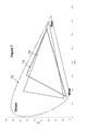
- FIG. 7 is a graphical depiction of chromaticity of R,G,B subpixels for different LED types in the CIE 1931 xy chromaticity diagram, wherein shape 12 is the gamut enclosing all visible colors, shape 13 is the gamut achievable by the W LED, and shape 14 is the gamut achievable by the RGB LEDs.
- FIG. 8 is a graphical depiction of chromaticity of R,G,B subpixels for RGB LEDs in the CIE 1931 xy chromaticity diagram, wherein shape 12 is the gamut enclosing all visible colors, shape 15 is the gamut achievable by the RGB LEDs being on one at a time, and shape 16 is the gamut achievable by the RGB LEDs being on together.
- a display device in a first embodiment, includes an LC display, with modified control electronics and backlight emitters.
- An LCD display generally has several component parts including:
- a backlighting unit to supply even, wide angle illumination to the panel.
- Control electronics to receive digital image data and output analogue signal voltages for each pixel, as well as timing pulses and a common voltage for the counter electrode of all pixels.
- a schematic of the standard layout of LCD control electronics is shown in FIG. 1 (adapted from Ilias Pappas, Stylianos Siskos and Charalambos A. Dimitriadis (2009). Active-Matrix Liquid Crystal Displays—Operation, Electronics and Analog Circuits Design, New Developments in Liquid Crystals, Georgiy V Tkachenko (Ed.), ISBN: 978-953-307-015-5, InTech, DOI: 10.5772/9686).
- control electronics 30 include a control ASIC 32 that receives data signals from a data line.
- the control ASIC 32 is configured with a DC/DC converter 34 to provide input signals to source driver ICs 36 and gate driver ICs 38 .
- Power is provided via an inverter 40 that also powers the backlight lamp 42 .
- the source and gate driver ICs provide the drive signals to the pixels 44 that form the LCD display.
- a liquid crystal (LC) panel for displaying an image by spatial light modulation, including two opposing glass substrates, onto one of which is disposed an array of pixel electrodes and active matrix array to direct the electronic signals, received from the control electronics, to the pixel electrodes. Onto the other substrate is usually disposed a uniform common electrode and color filter array film. Between the glass substrates is contained a liquid crystal layer of given thickness, usually 2-6 ⁇ m, which may be aligned by the presence of an alignment layer on the inner surfaces of the glass substrates. The glass substrates will generally be placed between crossed polarizing films and other optical compensation films to cause the electrically induced alignment changes within each pixel region of the LC layer to produce the desired optical modulation of light from the backlight unit and ambient surroundings, and thereby generate the image.
- LC liquid crystal
- embodiments of the present invention differ from a standard LCD in the backlight structure, and in the control electronics.
- image data is transferred from a processor elsewhere on the device to the control ASIC electronics 56 , and the data is analyzed by an image analysis component 52 and if necessary altered by an image conversion component 54 .
- the data is then sent to the gate 58 and source 60 driver ICs to be displayed on the panel by the pixels 74 .
- the backlight state is altered based on the image analysis.
- the backlight 62 includes different types of light sources with different spectral emissions, such that, in one embodiment, one type of light source being exclusively on will result in a different display image than the case of a different type of light source being exclusively on.
- a preferred case involves one broad spectrum LED 64 type with a white appearance, and three narrow spectrum LED types with emissions at red 66 , green 68 and blue 70 wavelengths respectively, which when combined give a white appearance.
- RGB LEDs are independently controllable by a backlight controller 72 .
- This embodiment is configured such that the W LED in combination with the color filter transmission windows makes the display capable of reproducing a given color gamut.
- the RGB LEDs have narrower emission spectra than the W LEDs, such that when used in combination with the same color filter they produce a larger gamut.
- the control electronics will aim to use the W LEDS where possible, and only exchange emission from the W LEDS for emission from the RGB LEDs when the input image data specifies resultant colors outside the gamut achievable by the W LEDs only.
- the system of this embodiment selects the optimum drive currents for each LED in the backlight such that image content can be faithfully displayed, according to an image standard or display specification, with color gamut that may exceed that achievable by the broadband emitter only, with a minimal power requirement.
- the optimal current or duty ratio for each LED type is calculated for each pixel.
- the extra colors present might be necessary to account for light from the green and blue LEDs leaking through the red color filter, for example.
- FIG. 3 is a graphical depiction of spectral transmission through color filters of a W LED wherein curve 1 is the transmission of the W LED through the Blue color filter, curve 2 is the transmission of the W LED through the Green color filter, and curve 3 is the transmission of the W LED through the Red color filter.
- FIG. 4 is a graphical depiction of spectral transmission through color filters for the case of RGB LEDs being on one at a time wherein curve 4 is the transmission of the B LED through the Blue color filter, curve 5 is the transmission of the G LED through the Green color filter, and curve 6 is the transmission of the R LED through the Red color filter.
- FIG. 3 is a graphical depiction of spectral transmission through color filters of a W LED wherein curve 1 is the transmission of the W LED through the Blue color filter, curve 2 is the transmission of the W LED through the Green color filter, and curve 3 is the transmission of the W LED through the Red color filter.
- FIG. 4 is a graphical depiction of spectral transmission through color filters for the case of
- FIG. 5 is a graphical depiction of spectral transmission through color filters for the case of all RGB LEDs being on together wherein curve 7 is the transmission of the RGB LEDs through the Blue color filter, curve 8 is the transmission of the RGB LEDs through the Green color filter, and curve 9 is the transmission of the RGB LEDs through the Red color filter.
- FIG. 6 is a graphical depiction of spectral transmission through the green color filter for the two cases of RGB LEDs all being on, and of just G LED being on wherein curve 10 is the transmission of the RGB LEDs through the green color filter, and curve 11 is the transmission of the G LED through the green color filter.
- FIG. 7 is a graphical depiction of chromaticity of R,G,B subpixels for different LED types in the CIE 1931 xy chromaticity diagram, wherein shape 12 is the gamut enclosing all visible colors, shape 13 is the gamut achievable by the W LED, and shape 14 is the gamut achievable by the RGB LEDs.
- shape 12 is the gamut enclosing all visible colors
- shape 13 is the gamut achievable by the W LED
- shape 14 is the gamut achievable by the RGB LEDs.
- shape 12 is the gamut enclosing all visible colors
- shape 15 is the gamut achievable by the RGB LEDs being on one at a time
- shape 14 is as before the gamut achievable by the RGB LEDs being on together.
- these LED duty ratios are calculated for each pixel as follows:
- control electronics stores the minimum required ratios of RGB LED duty ratios to W LED duty ratios. Also stored is the brightness of each color primary.
- Y c represents the required luminance of the color channel c
- S c represents the required ratio of the color channel c LED duty ratio to the white LED duty ratio.
- the duty ratio D of each color must be greater than, or equal to, the duty ratio of white multiplied by the previously calculated minimum ratio S for the color.
- the duty ratio D of each color multiplied by the brightness L of that LED at full duty ratio, plus the contribution from the White LED through that color's color filter, must be greater than, or equal to, the required brightness Y of this color.
- the total power P t is equal to the sum of all the individual LED powers for each LED type, which are each equivalent to its power requirement at full duty ratio P, multiplied by its duty ratio D.
- the duty ratio of each color must be greater than or equal to zero, and less than or equal to one.
- the next step is to minimize P t subject to these constraints and the constraints 1 to 6 above. This is a linear programming problem, which can be solved using standard methods, such as the simplex algorithm.
- the device of this embodiment will also have stored in its memory the color produced by different LED and color filter conditions. Specifically, the color produced by the LCD when one LED type is exclusively on at full duty ratio, and one color filter is fully transmissive. This color will possibly be represented in a device-independent color space, such as CIE XYZ. Since dimming LEDs with a duty ratio-based approach is a linear operation, as opposed to for example reducing the current which has a non-linear effect on the LED luminance, it is possible to accurately determine the color that will be produced through each color filter, for any state of LEDs, through simple addition. In this way, a matrix transformation can be constructed, as follows:
- R,G,B represents the transmission of the R,G,B color filters. This can be expressed in writing as, the total X component is equal to the X component produced by a fully transmissive red color filter, multiplied by its transmission, and so on for green and blue.
- the control electronics alters each pixel so that it will be displayed correctly with the new backlight state.
- the input image data in RGB format is converted into the device-independent color space, such as CIE XYZ as shown by equation 8.
- the coefficients of this matrix transformation can be chosen in a number of ways. For example, they could be from a defined color space such as sRGB, or Adobe RGB, or other color spaces. They could also be defined as the largest gamut available with the LEDs, or somewhere in between such that a color improvement is realized but the increase in power requirement is reduced.
- This 3 ⁇ 3 matrix is fixed for each LED type, and is usually referred to by M r , M g , M b , M w . Therefore, after the duty ratios have been determined, it is possible to calculate the XYZ color that will be produced by a given transmission of each LC color type:
- This matrix can be calculated just once per frame, and the resultant matrix is applied to each pixel to give new R,G,B values which are sent to the source and gate ICs to be shown on the panel.
- the R,G,B values produced will be outside the allowable range (e.g., less than 0% transmission or greater than 100% transmission, through that color filter.) This will particularly happen, but not exclusively, when the six principal coefficients calculated previously are calculated in such a way that there is some allowable loss of quality. For example, if there was some allowable loss of peak brightness, such that some pixels will not be shown as brightly as they are specified, then the RGB data produced by equation 12 will show an LC transmission greater than 100%.
- an LC transmission of less than 0% will be specified.
- the data might simply be clipped until it is achievable, or the other colors might be changed to maintain the hue of the pixel, or other methods might be used.
- the image data is scanned and for each pixel, six key variables are calculated (three absolute brightnesses, three ratios). Then the minimum allowable value for each six is determined by looking at the values of all the pixels being scanned, and from this the optimal (with regard to power consumption) duty ratios for each LED is calculated. Finally, the image data is processed to return optimal RGB data for the new backlight condition.
- this embodiment uses the known color rendering capabilities of the display using the different backlight emitters to accurately and efficiently calculate the minimum power backlighting conditions required to enable the display to produce the colors intended by the input image data, and then modifies the input image data according to the calculated backlighting conditions to ensure those intended colors are indeed produced and kept constant in appearance even as the input image data and backlighting conditions are changed in subsequent frames. This is a significant advantage of the invention over conventional configurations.
- a further significant advantage of this invention is that the use of the known color rendering capabilities of the display using the different backlight emitters in a device independent color space, allows cross-leakage of the different types of emitter through the different color filter windows to be accounted for. For example, increasing the duty ratio of the B LED will increase the transmission of light through the blue sub-pixels of the display, but also may increase the transmission of low wavelength bluish light through the green sub-pixels.
- Equations 9-12 allow this leakage to be accounted for, so that a display showing green image content having predominantly green LED illumination which changes in subsequent frames also includes some blue areas in the image, and therefore requires some emission from the blue LED, will not result in the color of the green regions changing, even though the chromaticity of light transmitted through the green sub-pixels will be altered.
- FIG. 6 shows the spectral transmission through the green color filter for the two cases of the G LED being fully on, and the G and B LEDs being fully on together.
- the display may be capable of a more saturated green color (or any other color) when only green image content is input and therefore only emission from the green LED is required, than when (for example) both fully saturated green and blue portions are present in the input image and therefore both blue and green LEDs are required to be emitting, reducing the effective saturation of the green and/or blue sub-pixels.
- This is shown in FIG. 8 , for a particular device with high Blue-Green leakage.
- the method of this embodiment allows the chromaticity of colours, such as pure green, to be kept constant, using the process of equations 9-12, despite these changing illumination conditions and therefore display primary color chromaticities, if the target color position associated with fully saturated input data is within the gamut achievable by the display when all of the red, green and blue emitters are on. However, it can be seen that this may limit the maximum saturation which may be displayed for image content including only or two primary colours.
- the target colour in device independent space for fully and highly saturated input data is varied according to which other highly saturated colours are present in the input image data.
- image data which is wholly green for example may be displayed with the maximum vividness of which the display is capable, and when the input image data contains both for example green and other colours, the chromaticity of the green regions is reduced.
- the display may allow this to be achieved in a gradual fashion so that sudden obtrusive changes to the color of image regions which are intended to remain constant do not occur.
- the image processing might selectively pause after completion of an image for a period of time.
- R,G,B duty ratios it may be preferable to consume less processing power in the calculation of the ideal R,G,B duty ratios.
- a number of more simple algorithms exist.
- a particular approach which may be suitable involves calculating the White level for each pixel as before, such that the required saturation and brightness can be realised in a power-efficient manner.
- the algorithm simply calculates R,G,B levels by subtracting the scaled contribution to each color channel from the W LED. In this approach, it is seen that it is still possible to have the optimal saturation for each of the three color primaries.
- a look up table approach to calculating the optimal LED duty ratios for each pixel.
- the optimal duty ratios for every pixel combination, or a given subset of every pixel combination may be interpolated.
- the look up table might be based on transforms of the image data, such as using HSV space instead of RGB, or any others.
- control electronics may consider the duty ratios calculated in the previous frame, and may restrict the change in LED duty ratios between frames, in certain circumstances.
- One benefit of this approach is to compensate for any timing problems between updating the LC layer and updating the backlight.
- the first half of the algorithm which calculates the optimal duty ratios
- the electronics analyze how many pixels are outside the available gamut produced by the previous frame's backlighting conditions, and how many are only just achievable. In so doing, it is possible to make incremental changes to the duty ratios to allow more vivid colors, brighter pixels, or to save power by reducing the LED duty ratios, or trading RGB duty ratio for W duty ratio which is a more efficient backlight state.
- the RGB data values might be converted into a different device-dependent color space, such as HSV.
- HSV device-dependent color space
- one method includes preparing a look-up table which contains, for certain hue angles, the saturation level at which it is no longer possible to display this color using only the broadband emitter. It will also contain the LED states required at a certain saturation level, such that when analysing each pixel, by converting it into HSV space, it is possible to quickly determine the extent, if any, that the narrowband emitters are needed.
- control electronics will store in its memory the conversion matrices of a number of different backlight states.
- the conversion from image data in RGB space, into RGB space for the new backlight state where the available backlight states might include the case of W LED fully on, and the case of RGB LEDs fully on, and the case of R,W LEDs fully on, and so on.
- the algorithm will cycle through each backlight state, preferably beginning with the least power-demanding, until a state is found which can suitably display the current image. Then, this backlight state is selected and the image is converted for accurate display as before.
- the image content can be plotted in a 3D chart in such a way that a convex hull can be calculated, which just encloses all the data points. Then, the algorithm calculates the LED duty ratios requiring minimal power consumption such that the 3D gamut produced by these LED states completely encloses the convex hull.
- this invention can be applied to displays in which there are no color filters, but instead R,G,B,W color components are displayed time sequentially to produce the required composite color.
- the claimed invention can analyze the image content and, in images where one or more colors are not fully saturated, can combine the White LED with other LEDs such that the power requirement is reduced without the image losing saturation.
- the present invention may be particularly advantageous for such color sequential displays as it allows the lower power W emitter to be used in one or two of the color periods only, retaining the maximal saturation of the remaining color fields unlike in the spatial color display of the principal embodiment in which any emission from the W LEDs reduces the saturation of all color components together.
- the conversion of color coordinates from RGB space into a device-independent color space is not a linear transformation using a 3 ⁇ 3 matrix.
- a new color space is developed which is a combination of two different spaces. It is well know that displays with a large color gamut can increase the vividness of colors in a way in which they were not intended to be shown. This may be acceptable for already vivid colors, but for pale colors such as skin tones, this can shift the colors so that their perceived appearance is significantly different from their true appearance, which often is not preferable for the viewer. Therefore, it is proposed that for pale colors, a pale color space is used, whose maximum vividness is relatively low, while for vivid colors, a more vivid color space is used.
- This may be a defined standard such as Adobe RGB, or it may simple be the maximum the display can produce, or other options. Then, depending on the saturation level of each pixel, a blend of the two color spaces is used to determine the desired XYZ level. This is used in calculating the optimal LED duty ratios, and later in the process flow when converting the image to be displayed in the new backlight state.
- the display includes a backlight portion having at least one broad spectrum emitter and at least one narrow spectrum emitter, wherein the broad spectrum emitter emits light of a broader spectrum that the narrow spectrum emitter, an image panel for displaying an image by spatial light modulation, and control electronics configured to receive input image data and output control signals to both the backlight portion and the image panel.
- the control electronics is configured to use color rendering capabilities of the image panel under illumination from each of the emitter types individually to calculate a minimum power combination of emission from each emitter type required to display the input image data.
- the control electronics is further configured to modify the input image data according to the calculated minimum power combination of emitter powers so a resulting display of colours in the image data remains despite changing illumination conditions.
- the broad spectrum emitter is a white emitter and the narrow spectrum emitter is at least one of red, green, and blue spectrum emitters.
- the image panel is operated without color filters, with the backlight to give time sequential color fields in multiple sub-frames, and the broad spectrum emitter is utilised either concurrently with one or more of the narrow spectrum emitters during any of the sub-frames, or in an additional sub-frame, to increase the brightness or power efficiency of the display at the expense of excess color saturation for one or more color components independently according to the input image data.
- the image panel is a liquid crystal panel that has red, green, and blue color filters.
- the liquid crystal panel further has a white color filter.
- control electronics processes the image data in a device independent color space to calculate the power combination of emitter powers.
- emitter powers are calculated using an extent to which pixels of the liquid crystal panel are outside a gamut achievable by the broadband emitter to determine a balance between the narrow spectrum emitters and the broad spectrum emitters.
- the emitter powers are calculated to minimize the power requirement of the backlight by solving a linear programming problem given by constraints of required brightness and required saturation.
- display colors of the input image data are specified by a known colour standard, and the input image data modification is configured to maintain constancy of all input colours under different emitter power combinations.
- control electronics continuously controls a changing color appearance of image regions with constant input image data when other regions of the image are changed.
- display colors of the input image data are a maximum gamut achievable by the display with all the narrow spectrum emitters on simultaneously.
- display colors of the input image data are a maximum gamut achievable by the display with the narrow spectrum emitters on individually.
- a measure of whether an increase or decrease in each of the emitter levels required is calculated, and the emitter power levels are incremented in a direction indicated according to the calculated increase or decrease requirement in each of the emitter levels.
- the emitter power values are calculated for every frame of input image data input to the display.
- the emitter power value calculations are performed asynchronously to the rest of the control electronics, and the image conversion uses most recently calculated and applied emitter powers.
- previous results of the emitter power calculation are taken into account and a change in emitter power to a next output combination is restricted, so as to smooth sudden changes in display backlight illumination.
- display colors of the input image data are based on a non-linear transformation of RGB data, or a blended combination of multiple color spaces based on the color's saturation level.
- the invention is applicable to any color transmissive display in which a wide colour gamut is desirable for at least some potential image content or usage scenario, and power consumption is a consideration.
Abstract
Description
- 1. W LED transmission through blue color filter
- 2. W LED transmission through green color filter
- 3. W LED transmission through red color filter
- 4. B LED transmission through blue color filter
- 5. B LED transmission through green color filter
- 6. B LED transmission through red color filter
- 7. RGB LEDs transmission through blue color filter
- 8. RGB LEDs transmission through green color filter
- 9. RGB LEDs transmission through red color filter
- 10. RGB LEDs transmission through green color filter
- 11. G LEDs transmission through green color filter
- 12. Gamut enclosing all visible colors
- 13. Gamut achievable by W LED
- 14. Gamut achievable by RGB LEDs
- 15. Gamut achievable by RGB LEDs one at a time
- 16. Gamut achievable by RGB LEDs on together
- 30. Control electronics
- 32. Control ASIC
- 34. DC/DC converter
- 36. Source Driver ICs
- 38. Gate Driver ICs
- 40. Inverter
- 42. Backlight lamp
- 44. LCD display pixels
- 50. LCD device
- 52. Image analysis component
- 54. Image conversion component
- 56. Control ASIC
- 58. Gate Driver ICs
- 60. Source Driver ICs
- 62. Backlight
- 64. W LED
- 66. Red LED
- 68. Green LED
- 70. Blue LED
- 72. Backlight controller
- 74. LCD display pixels
-
- Calculate the required LC transmission for each color filter, with the W LED on only.
- If any transmissions are negative, then the color is outside the W gamut:
- Calculate how far outside of the gamut this color is, by determining the most negative this transmission could have been.
- As an example, if the pixel has (R,G,B) data (255,40,30), this might lead to a transmission of (100%, 3%, −4%). Now calculate the transmission levels for the point (255,40,0), which might be (100%,2.5%, −16%). This implies that the color is −4/−16=25% out of gamut.
- Therefore, the W LED must contribute no more than 75% of the light required.
- Calculate the W LED duty ratio, by assuming all LCs are fully transmissive, and calculating the required XYZ color. This is done by multiplying the RGB pixel data by the target XYZ matrix as shown in
equation 8. - Then, using the stored data for XYZ color from a fully white state, determine with a simple division how far the W LED can be dimmed.
- As a final step, if any of the transmission levels were negative, the final W LED duty ratio will be a given a proportion of this dimming level.
- It will be seen that we have now calculated the optimal W LED duty ratio, such that the image point can be fully shown, and such that the RGB LEDs will not be used any more than necessary; in this way, the power requirement is minimized.
- If the pixel data is inside the W LED gamut, then the process can proceed to the next pixel. If it is not however, then it is necessary to calculate how much supplementary light is needed from the RGB LEDs. To this end the system operates as follows:
- Determine as before the required XYZ color, determine the XYZ color provided by the (dimmed) W LED, and therefore calculate how much is still required by the RGB LEDs.
- In general, the electronics will have stored in its memory, the XYZ color produced by different LED states with all LCs transmissive, as follows:
-
-
- Therefore, by inverting this matrix, the RGB duty ratios can be easily calculated.
- Finally, the ratio of RGB:W LED duty ratios is stored, as a constraint, since if the determined W LED duty ratio is too high relative to any of RGB, then some pixels in the image will be displayed as too pale.
-
D r ≧S r D w (1)
D g ≧S g D w (2)
D b ≧S b D w (3)
L r D r +L rw D w ≧Y r (4)
L g D g +L gw D w ≧Y g (5)
L b D b +L bw D w ≧Y b (6)
P t =D r P r +D g P g +D b P b +D w P w (7)
In this case, R,G,B represents the transmission of the R,G,B color filters. This can be expressed in writing as, the total X component is equal to the X component produced by a fully transmissive red color filter, multiplied by its transmission, and so on for green and blue.
Claims (17)
Priority Applications (2)
| Application Number | Priority Date | Filing Date | Title |
|---|---|---|---|
| US14/319,277 US9257095B2 (en) | 2014-06-30 | 2014-06-30 | Display device with a backlight |
| CN201510379001.6A CN105304026B (en) | 2014-06-30 | 2015-06-30 | Display equipment with backlight |
Applications Claiming Priority (1)
| Application Number | Priority Date | Filing Date | Title |
|---|---|---|---|
| US14/319,277 US9257095B2 (en) | 2014-06-30 | 2014-06-30 | Display device with a backlight |
Publications (2)
| Publication Number | Publication Date |
|---|---|
| US20150379960A1 US20150379960A1 (en) | 2015-12-31 |
| US9257095B2 true US9257095B2 (en) | 2016-02-09 |
Family
ID=54931191
Family Applications (1)
| Application Number | Title | Priority Date | Filing Date |
|---|---|---|---|
| US14/319,277 Expired - Fee Related US9257095B2 (en) | 2014-06-30 | 2014-06-30 | Display device with a backlight |
Country Status (2)
| Country | Link |
|---|---|
| US (1) | US9257095B2 (en) |
| CN (1) | CN105304026B (en) |
Families Citing this family (7)
| Publication number | Priority date | Publication date | Assignee | Title |
|---|---|---|---|---|
| US10600213B2 (en) * | 2016-02-27 | 2020-03-24 | Focal Sharp, Inc. | Method and apparatus for color-preserving spectrum reshape |
| CN107039006B (en) * | 2017-05-23 | 2019-02-19 | 北京小米移动软件有限公司 | Show method and device, the electronic equipment, computer readable storage medium of image |
| CN111448847B (en) * | 2017-12-07 | 2023-04-25 | 昕诺飞控股有限公司 | Illumination control system for controlling a plurality of light sources based on source image and method thereof |
| CN111105757B (en) * | 2018-10-26 | 2021-06-15 | 深圳Tcl新技术有限公司 | Liquid crystal display device and backlight driving method |
| CN112509476B (en) * | 2020-11-30 | 2022-10-21 | 錼创显示科技股份有限公司 | Micro light emitting diode display device |
| US11532271B1 (en) * | 2021-06-20 | 2022-12-20 | Purdue Research Foundation | Method and system of profiling display power |
| CN114354507A (en) * | 2021-12-30 | 2022-04-15 | 广域兴智能(南通)科技有限公司 | Spectrometer for detecting quantum optical material |
Citations (7)
| Publication number | Priority date | Publication date | Assignee | Title |
|---|---|---|---|---|
| US7106276B2 (en) | 2002-03-27 | 2006-09-12 | Citizen Watch Co., Ltd. | Color display device |
| US20070103934A1 (en) | 2005-11-10 | 2007-05-10 | Keh Kean L | System and method for constructing a backlighted display using dynamically optimized light source |
| US7333165B2 (en) | 2005-05-11 | 2008-02-19 | Sony Corporation | Liquid-crystal display apparatus and electronic device |
| US20080150864A1 (en) | 2006-12-21 | 2008-06-26 | Nokia Corporation | Displays with large dynamic range |
| US20090160756A1 (en) | 2006-05-09 | 2009-06-25 | Koninklijke Philips Electronics N.V. | Display device with a backlight |
| US20120242564A1 (en) * | 2011-03-22 | 2012-09-27 | Canon Kabushiki Kaisha | Backlight apparatus, control method therefor, and display apparatus |
| US8300069B2 (en) | 2006-05-24 | 2012-10-30 | Koninklijke Philips Electronics N.V. | Optimal backlighting determination apparatus and method |
Family Cites Families (4)
| Publication number | Priority date | Publication date | Assignee | Title |
|---|---|---|---|---|
| US20060209012A1 (en) * | 2005-02-23 | 2006-09-21 | Pixtronix, Incorporated | Devices having MEMS displays |
| BRPI0820651A2 (en) * | 2008-03-03 | 2019-09-24 | Sharp Kk | liquid crystal display device |
| PL2389670T3 (en) * | 2009-01-21 | 2019-03-29 | Guangdong Oppo Mobile Telecommunications Corp., Ltd. | Apparatus and methods for color displays |
| CN201489800U (en) * | 2009-07-24 | 2010-05-26 | 福建华映显示科技有限公司 | Display device capable of providing multiple operation modes |
-
2014
- 2014-06-30 US US14/319,277 patent/US9257095B2/en not_active Expired - Fee Related
-
2015
- 2015-06-30 CN CN201510379001.6A patent/CN105304026B/en not_active Expired - Fee Related
Patent Citations (7)
| Publication number | Priority date | Publication date | Assignee | Title |
|---|---|---|---|---|
| US7106276B2 (en) | 2002-03-27 | 2006-09-12 | Citizen Watch Co., Ltd. | Color display device |
| US7333165B2 (en) | 2005-05-11 | 2008-02-19 | Sony Corporation | Liquid-crystal display apparatus and electronic device |
| US20070103934A1 (en) | 2005-11-10 | 2007-05-10 | Keh Kean L | System and method for constructing a backlighted display using dynamically optimized light source |
| US20090160756A1 (en) | 2006-05-09 | 2009-06-25 | Koninklijke Philips Electronics N.V. | Display device with a backlight |
| US8300069B2 (en) | 2006-05-24 | 2012-10-30 | Koninklijke Philips Electronics N.V. | Optimal backlighting determination apparatus and method |
| US20080150864A1 (en) | 2006-12-21 | 2008-06-26 | Nokia Corporation | Displays with large dynamic range |
| US20120242564A1 (en) * | 2011-03-22 | 2012-09-27 | Canon Kabushiki Kaisha | Backlight apparatus, control method therefor, and display apparatus |
Non-Patent Citations (1)
| Title |
|---|
| Ilias Pappas, Stylianos Siskos and Charalambos A. Dimitriadis, "Active-Matrix Liquid Crystal Displays-Operation, Electronics and Analog Circuits Design", Nov. 2009. |
Also Published As
| Publication number | Publication date |
|---|---|
| US20150379960A1 (en) | 2015-12-31 |
| CN105304026B (en) | 2018-07-13 |
| CN105304026A (en) | 2016-02-03 |
Similar Documents
| Publication | Publication Date | Title |
|---|---|---|
| US9257095B2 (en) | Display device with a backlight | |
| US8681190B2 (en) | Liquid crystal display | |
| US8358293B2 (en) | Method for driving light source blocks, driving unit for performing the method and display apparatus having the driving unit | |
| US20140043371A1 (en) | Display control for multi-primary display | |
| CN104575402B (en) | Control circuit and display device equipped with the control circuit | |
| KR102058610B1 (en) | Apparatus for selecting backlight color values | |
| KR101994179B1 (en) | Method of facilitating display of image | |
| JP5301681B2 (en) | Liquid crystal display | |
| CN102347010B (en) | Liquid crystal display | |
| US8766893B2 (en) | Method for compensating for poor uniformity of liquid crystal display having non-uniform backlight and display that exhibits non-uniformity compensating function | |
| WO2009110129A1 (en) | Liquid crystal display device | |
| US7705815B2 (en) | Backlight control unit and liquid crystal display device having the same | |
| US20100321414A1 (en) | Display device | |
| WO2011036916A1 (en) | Display device and display method therefor | |
| US20070247415A1 (en) | Method for driving liquid crystal display assembly | |
| EP2309761A1 (en) | A method for processing video data for a liquid crystal display | |
| US20120293571A1 (en) | Image display device | |
| US20130120478A1 (en) | Display signal generator, display device, and method of image display | |
| KR101399130B1 (en) | Back Light Unit Driving Apparatus | |
| KR101715854B1 (en) | Method and unit converting color temperature for improving emotional image quality and digital display apparatus using the same | |
| KR102222725B1 (en) | Method for reducing simultaneous contrast error | |
| CN113409738A (en) | Backlight source circuit, control method thereof and display device |
Legal Events
| Date | Code | Title | Description |
|---|---|---|---|
| AS | Assignment |
Owner name: SHARP KABUSHIKI KAISHA, JAPAN Free format text: ASSIGNMENT OF ASSIGNORS INTEREST;ASSIGNORS:HEYWOOD-LONSDALE, EDWARD DAVID;BROUGHTON, BENJAMIN JOHN;WALTON, EMMA JAYNE;AND OTHERS;SIGNING DATES FROM 20140627 TO 20140630;REEL/FRAME:033231/0908 |
|
| ZAAA | Notice of allowance and fees due |
Free format text: ORIGINAL CODE: NOA |
|
| ZAAB | Notice of allowance mailed |
Free format text: ORIGINAL CODE: MN/=. |
|
| FEPP | Fee payment procedure |
Free format text: PAYOR NUMBER ASSIGNED (ORIGINAL EVENT CODE: ASPN); ENTITY STATUS OF PATENT OWNER: LARGE ENTITY |
|
| STCF | Information on status: patent grant |
Free format text: PATENTED CASE |
|
| MAFP | Maintenance fee payment |
Free format text: PAYMENT OF MAINTENANCE FEE, 4TH YEAR, LARGE ENTITY (ORIGINAL EVENT CODE: M1551); ENTITY STATUS OF PATENT OWNER: LARGE ENTITY Year of fee payment: 4 |
|
| FEPP | Fee payment procedure |
Free format text: MAINTENANCE FEE REMINDER MAILED (ORIGINAL EVENT CODE: REM.); ENTITY STATUS OF PATENT OWNER: LARGE ENTITY |
|
| LAPS | Lapse for failure to pay maintenance fees |
Free format text: PATENT EXPIRED FOR FAILURE TO PAY MAINTENANCE FEES (ORIGINAL EVENT CODE: EXP.); ENTITY STATUS OF PATENT OWNER: LARGE ENTITY |
|
| STCH | Information on status: patent discontinuation |
Free format text: PATENT EXPIRED DUE TO NONPAYMENT OF MAINTENANCE FEES UNDER 37 CFR 1.362 |
|
| FP | Lapsed due to failure to pay maintenance fee |
Effective date: 20240209 |