US9230309B2 - Image processing apparatus and image processing method with image inpainting - Google Patents
Image processing apparatus and image processing method with image inpainting Download PDFInfo
- Publication number
- US9230309B2 US9230309B2 US14/243,913 US201414243913A US9230309B2 US 9230309 B2 US9230309 B2 US 9230309B2 US 201414243913 A US201414243913 A US 201414243913A US 9230309 B2 US9230309 B2 US 9230309B2
- Authority
- US
- United States
- Prior art keywords
- removal
- pixel values
- region
- pixels
- patch
- Prior art date
- Legal status (The legal status is an assumption and is not a legal conclusion. Google has not performed a legal analysis and makes no representation as to the accuracy of the status listed.)
- Active, expires
Links
- 238000012545 processing Methods 0.000 title claims abstract description 158
- 238000003672 processing method Methods 0.000 title claims description 17
- 239000000203 mixture Substances 0.000 claims abstract description 22
- 238000000034 method Methods 0.000 claims description 47
- 230000008569 process Effects 0.000 claims description 30
- 238000002156 mixing Methods 0.000 claims description 8
- 238000003384 imaging method Methods 0.000 claims description 2
- 238000010586 diagram Methods 0.000 description 17
- 238000004364 calculation method Methods 0.000 description 10
- 239000004973 liquid crystal related substance Substances 0.000 description 7
- 239000000470 constituent Substances 0.000 description 5
- 230000008859 change Effects 0.000 description 3
- 238000004590 computer program Methods 0.000 description 3
- 230000009467 reduction Effects 0.000 description 3
- 238000007792 addition Methods 0.000 description 2
- 238000006243 chemical reaction Methods 0.000 description 2
- 238000004891 communication Methods 0.000 description 2
- 238000012986 modification Methods 0.000 description 2
- 230000004048 modification Effects 0.000 description 2
- 239000004065 semiconductor Substances 0.000 description 2
- 238000012935 Averaging Methods 0.000 description 1
- XUIMIQQOPSSXEZ-UHFFFAOYSA-N Silicon Chemical compound [Si] XUIMIQQOPSSXEZ-UHFFFAOYSA-N 0.000 description 1
- 230000001419 dependent effect Effects 0.000 description 1
- 230000009977 dual effect Effects 0.000 description 1
- 238000005516 engineering process Methods 0.000 description 1
- 230000001815 facial effect Effects 0.000 description 1
- 229910052710 silicon Inorganic materials 0.000 description 1
- 239000010703 silicon Substances 0.000 description 1
- 238000006467 substitution reaction Methods 0.000 description 1
Images


Classifications
-
- G—PHYSICS
- G06—COMPUTING; CALCULATING OR COUNTING
- G06T—IMAGE DATA PROCESSING OR GENERATION, IN GENERAL
- G06T5/00—Image enhancement or restoration
- G06T5/77—Retouching; Inpainting; Scratch removal
-
- G06T5/005—
-
- G—PHYSICS
- G06—COMPUTING; CALCULATING OR COUNTING
- G06T—IMAGE DATA PROCESSING OR GENERATION, IN GENERAL
- G06T2207/00—Indexing scheme for image analysis or image enhancement
- G06T2207/20—Special algorithmic details
- G06T2207/20092—Interactive image processing based on input by user
- G06T2207/20104—Interactive definition of region of interest [ROI]
Definitions
- the present disclosure relates to an image processing technique for inpainting a portion of an image that is not as intended by a user.
- an image includes an unnecessary object, which is an object thought to be unnecessary by a user (such as facial blemishes or moles, or electric cables in the background).
- an unnecessary object which is an object thought to be unnecessary by a user (such as facial blemishes or moles, or electric cables in the background).
- a function for performing inpainting processing after removing such an unnecessary object from the image has been proposed.
- an image processing method has been proposed in which inpainting is performed by attaching the pixel values in a non-missing region to a missing region, which is a region from which an unnecessary object was removed.
- patch sets including a missing patch, which is an image of a region that includes a missing region, and a reference patch, which is an image of a region that does not include a missing region are provided, patch sets in which the missing patch and the reference patch are comparatively similar are selected, and then a patch set in which the missing patch image and the reference patch image are comparatively similar is selected based on the relationship between estimated pixel values in a missing region of the missing patch and the corresponding pixel values of the reference patch.
- the missing patch is then inpainted based on the reference patch in the patch set that was selected (e.g., see WO 2011/061943).
- the present disclosure provides an image processing apparatus and an image processing method that are effective for obtaining a more natural processing result in image inpainting processing for removing an unnecessary object from an image.
- the image processing apparatus is an image processing apparatus that inpaints a inpainting target region in an image to be displayed.
- the image processing apparatus comprises: a display unit configured to display the image constituted by a predetermined number of pixels; and a control unit configured to control the display unit.
- the control unit is configured to determine a removal patch including a removal region that is the inpainting target region and a first non-removal region that is a region that does not include the removal region in the image to be displayed on the display unit, and replace pixel values of pixels included in the removal region with pixel values of pixels outside the removal patch.
- the control unit is further configured to calculate a distance from the removal region for pixels included in the first non-removal region, blend pixel values of the pixels included in at least a portion of the first non-removal region with the pixel values of the pixels outside the removal patch based on the calculated distance to obtain blended pixel values, and replace the pixel values of the pixels included in the at least a portion of the first non-removal region with the blended pixel values.
- the image processing method is an image processing method for inpainting a inpainting target region in an image to be displayed on a display unit, the image processing method including: determining a removal patch including a removal region that is the inpainting target region and a non-removal region that is a region that does not include the removal region in the image to be displayed on the display unit; replacing pixel values of pixels included in the removal region with pixel values of pixels outside the removal patch; calculating a distance from the removal region for pixels included in the non-removal region; blending pixel values of the pixels included in at least a portion of the non-removal region with the pixel values of the pixels outside the removal patch based on the calculated distance to obtain blended pixel values; and replacing the pixel values of the pixels included in the at least a portion of the non-removal region with the blended pixel values.
- the image processing apparatus and the image processing method of the present disclosure are effective for obtaining a more natural processing result in image inpainting processing for removing an unnecessary object from an image.
- FIG. 1 is a block diagram showing a schematic configuration of an image processing apparatus.
- FIG. 2 is a flowchart showing operations of the image processing apparatus.
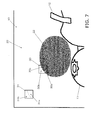
- FIG. 3 is a diagram showing an image resulting from reduction processing.
- FIG. 4 is a flowchart showing operations in region designation processing.
- FIG. 5 is a diagram for describing the state of a binary image generated as a result of the region designation processing.
- FIG. 6 is a flowchart showing operations in reduced image inpainting processing.
- FIG. 7 is a diagram for describing the relationship between a first removal patch and a reference patch in the reduced image inpainting processing.
- FIG. 8 is a diagram for describing the positions of removal/reference patches recorded as a patch history.
- FIG. 9 is a diagram showing the distance that the non-removal region is separated from the removal region for each pixel in the reduced image inpainting processing.
- FIG. 10 is a diagram for describing a result of removal patch inpainting.
- FIG. 11 is a diagram for describing the relationship between a second removal patch and a reference patch.
- FIG. 12 is a diagram showing the distance that the non-removal region is separated from the removal region for each pixel.
- FIG. 13 is a diagram for describing a result of removal patch inpainting.
- FIG. 14 is a diagram for describing a result of operations in the reduced image inpainting processing.
- FIG. 15 is a flowchart showing operations in original image inpainting processing.
- FIG. 16 is a diagram for describing the relationship between a third removal patch and a reference patch according to a variation.
- FIG. 17 is a diagram showing the distance that the non-removal region is separated from the removal region for each pixel according to the variation.
- Embodiment 1 will be described below with reference to FIGS. 1 to 17 .
- FIG. 1 is a block diagram schematically showing the configuration of an image processing apparatus 1 .
- the image processing apparatus 1 is any electronic device, such as a digital still camera, a digital video camera, a personal computer, a mobile phone, or an information terminal.
- the image processing apparatus 1 includes a control unit 2 (example of a control unit) that performs overall control of operations of units in the image processing apparatus 1 ; an image input unit 3 , such as a camera or a scanner, that includes a lens and an imaging device and captures images; a storage unit 4 that records various types of information such as captured images; a display unit 5 (example of a display unit), such as a liquid crystal monitor or an organic EL display, that displays image information such as images; and an operation input unit 6 , such as a touch panel, that receives an input of various types of operations from a user.
- a control unit 2 example of a control unit
- an image input unit 3 such as a camera or a scanner, that includes a lens and an imaging
- the control unit 2 includes a processor such as a CPU, and executes operations of the image processing apparatus 1 by executing processing according to a predetermined program.
- the storage unit 4 may be constituted by a hard disk, a silicon disk, an SD card (semiconductor memory), or the like.
- the storage unit 4 may be constituted by an element that performs temporary storage, such as a cache or a RAM.
- the operation input unit 6 may be a pointing device such as a mouse or a tablet, or may be a keyboard.
- the operation input unit 6 may be an electronic pen of any of various systems, or the like.
- the control unit 2 of the image processing apparatus 1 generates a reduced image from an image captured by the image input unit 3 .
- an image captured by the image input unit 3 is stored in the storage unit 4 in advance, that image is read out from the storage unit 4 , and the reduced image is generated.
- the generated reduced image is then displayed on the display unit 5 (step S 101 ).
- control unit 2 recognizes an arbitrary region that was designated by the user in the reduced image, for example, and generates a binary image in which the pixels included in the designated region make up a removal region (step S 102 ).
- control unit 2 performs reduced image inpainting processing on the removal region, as well as stores the procedure of the inpainting processing (step S 103 ).
- control unit 2 uses the stored inpainting processing procedure to perform inpainting processing on the image from before the reduction performed in step S 101 (original image) (step S 104 ).
- step S 101 The following is a more detailed description of operations in the reduced image display processing (step S 101 ), the region designation processing (step S 102 ), the reduced image inpainting processing (step S 103 ), and the original image inpainting processing (step S 104 ) shown in the flowchart of FIG. 2 .
- FIG. 3 is a diagram showing a state in which a reduced image is displayed on a liquid crystal screen.
- An image captured by the image input unit 3 or an image stored in the storage unit 4 is constituted from 4,480 pixels horizontally and 3,360 pixels vertically, for example.
- Each pixel has three pieces of digital data (referred to hereinafter as the “pixel value”) respectively indicating a luminance Y and color differences U and V. Note that since the image data format allows conversion between color spaces such as the RGB color space and the Lab color space, processing may be performed using the results of conversion into another color space as the pixel value.
- the number of pixels in the liquid crystal screen serving as the display unit 5 is generally lower than with this type of image constituted from a large number of pixels (referred to hereinafter as the “original image”).
- original image a large number of pixels
- the following description will take the example of a liquid crystal screen constituted from 640 display pixels horizontally and 480 display pixels vertically.
- the control unit 2 generates a reduced image by reducing the original image to 1/K.
- K 7
- the original image is evenly divided into square blocks made up of K ⁇ K (i.e., 7 ⁇ 7) pixels. This results in 640 blocks horizontally and 480 blocks vertically. In view of this, it is sufficient to select the center pixel of each block, and use the pixel values of the center pixels as the pixel value of the reduced image 10 (thinning processing).
- a configuration is possible in which average values are calculated for the three luminance Y and color difference U and V components of the pixel values of the 49 pixels included in each block, and the resulting average values are used as the pixel values of the reduced image 10 (averaging processing).
- FIG. 3 shows an example where the reduced image generated by the control unit 2 in this way is displayed on the liquid crystal screen serving as the display unit 5 .
- the reduced image 10 obtained by reducing the original image to 1/K includes a first subject 11 , a second subject 12 , a third subject 13 , and the like.
- the following description will take the example of the case where the first subject 11 among these three subjects is set as the unnecessary object and removed, and then inpainting processing is performed on the removal region.
- FIG. 4 is a flowchart showing operations in region designation processing performed by the image processing apparatus 1 .
- FIG. 5 is a diagram for describing a state in which a removal region designated as an unnecessary object is generated as a binary image.
- the control unit 2 of the image processing apparatus 1 displays the reduced image 10 on the liquid crystal screen serving as the display unit 5 ( FIG. 3 ), and then prompts the user to perform input.
- the user touches the liquid crystal screen with their fingertip and traces the outline portion of the first subject 11 .
- the control unit 2 successively records the position of the fingertip detected by the touch panel serving as the operation input unit 6 , and obtains a closed curve that encloses the first subject 11 .
- the interior of this closed curve is then determined to be an unnecessary object (step S 201 ).
- the designation of the unnecessary object does not need to be dependent on user input as described above, and the unnecessary object may be detected automatically.
- a configuration is possible in which a line-shaped flaw such as debris or a scratch is automatically detected, and that flaw is automatically detected as the unnecessary object.
- it is also effective to use a procedure of dividing the screen into several candidate regions (e.g., the first subject 11 , the second subject 12 , and the third subject 13 ) by determining differences in color, brightness, or the like. The user may be allowed to select one or more regions from among the candidates.
- the control unit 2 After the unnecessary object has been recognized as described above, the control unit 2 generates a binary image in which the pixels included in the unnecessary object make up a removal region. Specifically, the binary image is generated such that the values of the pixels inside the closed curve that encloses the first subject 11 are 1 (true), and the values of the pixels outside the closed curve are 0 (false) (step S 202 ).
- FIG. 5 shows an example of a binary image 21 generated in this way. The number of pixels in the binary image is the same as the number of pixels in the reduced image 10 .
- the pixels that have the value of 1 and are included in a removal region 22 are shown in gray, and the pixels that have the value of 0 and are included in a non-removal region 23 are shown in white. The same follows the figures in the description below.
- FIG. 6 is a flowchart showing operations in reduced image inpainting processing performed by the image processing apparatus 1 .
- FIGS. 7 to 13 show operations in the reduced image inpainting processing.
- the control unit 2 performs image inpainting processing on the reduced image 10 , specifically on the removal region 22 that underwent the binary image processing (step S 103 in FIG. 2 ).
- FIG. 7 is an enlarged view of the periphery of the removal region 22 of the binary image superimposed on the reduced image 10 in FIG. 3 that is subjected to processing.
- the control unit 2 determines a square removal patch 30 whose center is on an edge portion of the removal region 22 (the boundary of the region, which is a boundary line portion between the interior and exterior of the region) (step S 301 ).
- the removal patch 30 is arranged so as to span the removal region 22 and the non-removal region 23 .
- the removal patch 30 has 16 pixels horizontally and 16 pixels vertically, for example. These 256 pixels can be divided into the following two regions. Specifically, the first region is made up of the pixels that are included in a removal region 30 a of the removal patch 30 , and the second region is made up of the pixels that are included in a non-removal region 30 b . A boundary 30 c between these two regions conforms to the edge portion of the removal region 22 .
- the control unit 2 selects a reference patch 31 that corresponds to the removal patch 30 (step S 302 ).
- the reference patch 31 is a square region made up of only pixels in the non-removal region 23 , and has the same number of pixels as the removal patch 30 . Since the reduced image 10 includes many candidates that satisfy this condition, the reference patch is selected using the following procedure. Specifically, a degree of similarity is obtained for the non-removal region 30 b of the removal patch 30 and a corresponding partial region 31 b of each reference patch 31 . The reference patch 31 that has the highest degree of similarity is selected from among the candidates.
- the degree of similarity is calculated using a method such as the following.
- the sum of squares is obtained for the difference between the pixel values of the pixels included in the non-removal region 30 b of the removal patch 30 and the pixel values of the corresponding pixels included in the partial region 31 b of each reference patch 31 . It is sufficient that the smaller the sum of squares is, the higher the degree of similarity is determined to be.
- one set of the removal patch 30 and a corresponding reference patch 31 is selected, and therefore the control unit 2 records this result in the storage unit 4 as a patch history (step S 303 ). It is sufficient that information such as that shown in FIG. 8 is recorded with a history number 1. Specifically, the central position (Xc,Yc) of the removal patch 30 , the center (Xs,Ys) of the reference patch 31 , and the size P of the removal patch (e.g., 16 pixels) are recorded.
- the control unit 2 calculates a distance D from the removal region 30 a for each pixel included in the non-removal region 30 b of the removal patch 30 (step S 304 ).
- FIG. 9 shows the result of calculating the distance D for all of the 16 ⁇ 16 pixels.
- the pixels included in the non-removal region 30 b are marked with distance D numerical values indicating the shortest distance from the removal region 30 a obtained as a city block distance (Manhattan distance).
- the present disclosure is not limited to using a city block distance in the method of calculating the shortest distance, and a normal distance (Euclidean distance) or the like may be used.
- the processing speed can be increased when using a city block distance since only integer arithmetic needs to be performed.
- the processing speed can be increased since there is no need to calculate the distance for all of the pixels included in the reduced image 10 or the binary image 21 (640 ⁇ 480 pixels).
- control unit 2 uses the following procedure to carry out inpainting processing on the removal patch 30 using the pixel values of the pixels in the reference patch 31 (step S 305 ).
- the pixel values of the pixels in the removal region 30 a of the removal patch 30 are replaced with the pixel values of the corresponding pixels in the partial region 31 a of the reference patch 31 .
- the portions shown in dark gray are pixels that are subjected to this process.
- the pixel values of the pixels for which the distance D is less than a predetermined threshold value Dw are subjected to later-described blend processing that is performed using the pixel values of the corresponding pixels in the partial region 31 b of the reference patch 31 .
- Dw a predetermined threshold value
- a region 30 d shown in light gray in FIG. 9 is made up of the pixels that are subjected to this process.
- the current pixel values are saved for the pixels for which the distance D is greater than or equal to the threshold value of Dw (i.e., D ⁇ Dw).
- Dw the threshold value of Dw
- a blend ratio of the pixel value Pc of that pixel to the pixel value Ps of the corresponding pixel in the reference patch 31 is determined to be D/Dw to (Dw ⁇ D)/Dw.
- the result of blending Pc and Ps based on the determined blend ratio is then again substituted for the pixel value Pc.
- the blend ratio of Pc to Ps changes according to the distance D. Accordingly, blended images in which the pixel value shifts from Pc to Ps are obtained between the first process and the third process.
- FIG. 10 shows the result of performing the inpainting processing on the removal patch 30 as described above.
- the removal region 30 a of the removal patch 30 is replaced with the corresponding partial region 31 a of the reference patch 31 . Accordingly, the inpainting processing is performed on a portion of the removal region 22 . Furthermore, since the second process described above is performed, the portion corresponding to the boundary 30 c does not stand out unnaturally.
- the values of the distance D and the threshold value Dw need only be numerical values that are less than or equal to half the size S of the removal patch 30 , that is to say satisfy the condition Dw ⁇ S/2.
- control unit 2 updates the removal region 22 (step S 306 ). Specifically, the binary image 21 that was generated in step S 202 in FIG. 4 is updated. The pixels in the region of the removal region 22 that corresponds to the removal patch 30 are changed to the non-removal region 23 by changing their pixel values to 0. This processing is necessary for properly carrying out later-described step S 307 . This processing is also necessary for correctly calculating the distance D (step S 304 ) in the second and successive iterations.
- control unit 2 determines whether or not a removal region 22 remains (step S 307 ). This determination may be performed by searching all of the pixels in the binary image 21 for a pixel having the value of 1. If even one pixel has the value of 1, a removal region 22 remains, and therefore the procedure returns to step S 301 , and processing is performed a second time.
- the control unit 2 performs the processing of steps S 301 to S 306 shown in the flowchart of FIG. 6 .
- a square removal patch 32 whose center is on the edge portion of the removal region 22 is determined as shown in FIG. 11 (step S 301 ).
- the removal patch 32 is constituted from the pixels that are included in a removal region 32 a and the pixels that are included in a non-removal region 32 b .
- Boundaries 32 c and 32 f between these two regions conform to the edge portion of the removal region 22 .
- the boundary 32 f is a new boundary that appeared as a result of the processing in the first iteration. Specifically, it is a new boundary generated as a result of replacing the removal region 30 a of the removal patch 30 with the corresponding partial region 31 a of the reference patch 31 .
- control unit 2 selects a reference patch 33 that corresponds to the removal patch 32 (step S 302 ).
- the reference patch 33 is selected based on the degree of similarity between the non-removal region 32 b of the removal patch 32 and a corresponding partial region 33 b of the reference patch 33 .
- control unit 2 records the removal patch 32 and the result of selecting the corresponding reference patch 33 with a history number 2 in the patch history (step S 303 ).
- the control unit 2 calculates a distance D from the removal region 32 a for each pixel included in the non-removal region 32 b of the removal patch 32 (step S 304 ).
- FIG. 12 shows the result of calculating the distance D for all of the 16 ⁇ 16 pixels. Since the removal region 22 is updated in step S 306 in the first iteration, it is possible to calculate a distance D that also corresponds to the new boundary 32 f that was generated in the first iteration.
- control unit 2 uses the following procedure to carry out inpainting processing on the removal patch 32 using the pixel values of the pixels in the reference patch 33 (step S 305 ).
- the pixel values of the pixels in the removal region 32 a of the removal patch 32 are replaced with the pixel values of the corresponding pixels in the partial region 33 a of the reference patch 33 .
- the pixels for which the distance D is less than the predetermined threshold value Dw that is to say D ⁇ Dw (the pixels in a region 32 d in FIG. 12 ) are subjected to the blend processing in accordance with the calculation formula shown in Equation 1.
- the blend ratio of the pixel value Pc of that pixel to the pixel value Ps of the corresponding pixel in the partial region 33 b of the reference patch 31 is determined to be D/Dw to (Dw ⁇ D)/Dw.
- the result of blending Pc and Ps based on the determined blend ratio is then again substituted for the pixel value Pc.
- the current pixel values are saved for the pixels for which the distance D is greater than or equal to the threshold value of Dw.
- the pixels in a region 32 e in FIG. 12 are not subjected to any processing.
- FIG. 13 shows the result of performing the inpainting processing on the removal patch 32 as described above.
- the removal region 32 a of the removal patch 32 is replaced with the corresponding partial region 33 a of the reference patch 33 . Accordingly, the inpainting processing is performed on a portion of the removal region 22 . Furthermore, since the second process described above is performed, the portion corresponding to the boundaries 32 c and 32 f does not stand out unnaturally.
- the boundary 32 c shown in FIG. 11 is a boundary that already existed at the stage of the region designation processing in step S 102 of FIG. 2 .
- the boundary 32 f is a new boundary that was generated in the processing in the first iteration.
- the removal region 22 is always updated in step S 305 , and therefore the new boundary 32 f that was generated does not stand out either, and a natural processing result is obtained.
- control unit 2 updates the removal region 22 (step S 306 ).
- the pixels in the region of the removal region 22 that corresponds to the removal patch 32 are changed to the non-removal region 23 by changing their pixel values to 0.
- control unit 2 determines whether or not a removal region 22 remains (step S 307 ). Steps S 301 to S 306 are then repeatedly executed until no removal region 22 remains. As a result, steps S 301 to S 306 are repeated N times. As shown in FIG. 14 , a natural inpainting processing result in which the first subject 11 has been removed from the reduced image 10 is obtained.
- the distance D from the removal region 22 is calculated for each pixel in the non-removal region 23 in the removal patch (step S 304 ).
- the pixel values of the pixels in the removal region 22 of the removal patch are then replaced with the pixel values of the corresponding pixels in the reference patch (step S 305 ), and among the pixels in the non-removal region 23 of the removal patch, pixels for which the distance D is less than the predetermined threshold value Dw (i.e., D ⁇ Dw) are subjected to the blend processing so as to be blended in accordance with the calculation formula shown in Equation 1 (step S 305 ).
- Dw predetermined threshold value
- the removal region 22 is updated (step S 306 ).
- new boundaries that are generated a result of the pixel value replacement (boundaries between the removal region 22 and the non-removal region 23 ) also do not stand out unnaturally, and a natural processing result is obtained.
- FIG. 15 is a flowchart showing operations in inpainting processing performed on the original image
- the control unit 2 generates a binary image that has the same number of pixels as the original image by enlarging the binary image 21 that corresponds to the reduced image 10 to a factor of K (step S 401 ).
- the enlargement factor K is the inverse of the reduction factor 1/K in step S 101 in FIG. 2 . For example, if an image enlarged to a factor of 7 vertically and horizontally is generated from a binary image having 640 pixels vertically ⁇ 480 pixels horizontally, a binary image having 4,480 ⁇ 3,360 pixels will be obtained.
- the binary image 21 that is subjected to the enlargement processing is the binary image that was generated in step S 202 in FIG. 4 .
- the binary image that is subjected to the enlargement processing is the binary image 21 that includes the removal region 22 as shown in FIG. 5 .
- the objective of step S 401 is to enlarge the position and size of the removal region 22 to a factor of K.
- control unit 2 performs the processing of loop A on all of the patch histories (step S 402 ) that were recorded in the reduced image inpainting processing (step S 103 in FIG. 2 ).
- the processing of loop A is executed the same number of times as the repetition number N (the repetition number N from steps S 301 to S 306 in FIG. 6 ) in the reduced image inpainting processing (step S 103 in FIG. 2 ).
- the patch histories are reproduced in the order that they were recorded in the reduced image inpainting processing (step S 103 in FIG. 2 ).
- the processing of steps S 403 , S 404 , S 405 , and S 406 in FIG. 15 is then executed using the patch history that was recorded in step S 303 in FIG. 6 .
- the control unit 2 calculates the positions and sizes of the removal patch and the reference patch with respect to the original image (step S 403 ).
- the enlargement factor K of the reduced image 10 and the original image is used to perform the calculation shown below.
- the central position of the removal patch 30 is calculated according to (K ⁇ Xc,K ⁇ Yc)
- the central position of the reference patch 31 is calculated according to (K ⁇ Xs,K ⁇ Ys)
- control unit 2 calculates the distance D from the removal region for each pixel included in the non-removal region of the removal patch (step S 404 ). For example, in the case of a removal patch made up of 112 ⁇ 112 pixels, the shortest distance D from the removal region calculated in step S 401 is calculated as a city block distance.
- control unit 2 uses the following procedure to carry out inpainting processing on the removal patch using the pixel values of the pixels in the reference patch (step S 405 ).
- the pixel values of the pixels in the removal region of the removal patch are replaced with the pixel values of the corresponding pixels of the reference patch.
- the current pixel values are saved for the pixels for which the distance D is greater than or equal to M ⁇ Dw (i.e., D ⁇ M ⁇ Dw).
- D ⁇ M ⁇ Dw the pixels in the region 30 e shown in white in FIG. 9 are not subjected to any processing.
- step S 405 Letting Pc be the pixel value of a pixel in the removal patch, and Ps be the pixel value of the corresponding pixel in the reference patch, the second process is executed according to Equation 2 below. D indicates the distance of this pixel.
- the blend ratio of the pixel value Pc of that pixel to the pixel value Ps of the corresponding pixel in the reference patch is determined to be D/(M ⁇ Dw) to (mxDw ⁇ D)/M ⁇ Dw.
- the result of blending Pc and Ps based on the determined blend ratio is then again substituted for the pixel value Pc.
- control unit 2 updates the removal region (step S 406 ).
- the pixels in the region that corresponds to the removal patch are changed to the non-removal region by changing their pixel values to 0.
- step S 403 when the processing of steps S 403 , S 404 , S 405 , and 5406 has been carried out on all of the patch histories (step S 402 ) that were recorded in the reduced image inpainting processing (step S 103 ), original image inpainting processing is complete.
- step S 402 original image inpainting processing is completed by merely carrying out the processing of step S 402 on all of the patch histories that were recorded in the reduced image inpainting processing (step S 103 in FIG. 2 ). Accordingly, there is no need to again select a reference patch that corresponds to the removal patch. In other words, there is no need for processing that corresponds to step S 302 in FIG. 6 , thus making it possible to increase the processing speed.
- the degree of similarity is calculated for the removal patch and the reference patch in step 302 .
- the effort for calculating this degree of similarity is proportional to the number of pixels.
- the number of reference patches that are candidates is also proportional to the number of pixels. Accordingly, the calculation effort required to select a reference patch is proportional to the square of the number of pixels.
- processing corresponding to step S 302 has been carried out on an original image. With an original image that is a factor of K (e.g., a factor of 7) of the reduced image 10 , the number of pixels increases to the square of K (a factor of 49). Accordingly, a calculation effort corresponding to the fourth power of K (a factor of 2,401) is required to select a corresponding reference patch based on the removal patch enlarged to a factor of K.
- the distance D from the removal region is calculated for each pixel in the non-removal region of the removal patch (step S 404 ). Then, the pixel values of the pixels in the removal region of the removal patch are replaced with the pixel values of the corresponding pixels of the reference patch (step S 405 ), and among the pixels in the non-removal region of the removal patch, the pixel values of the pixels for which the distance D is less than M ⁇ Dw (i.e., D ⁇ M ⁇ Dw), are subjected to the blend processing so as to be blended in accordance with the calculation formula shown in Equation 2 (step S 405 ).
- M ⁇ Dw i.e., D ⁇ M ⁇ Dw
- step S 304 and step S 305 in FIG. 6 described in the above embodiment, or the processing in step S 404 and step S 405 in FIG. 15 can be replaced with a processing method such as that described below.
- the following description takes the example of the reduced image inpainting processing of step S 103 in FIG. 2 .
- FIGS. 16 and 17 are diagrams for describing operations in this variation.
- step S 307 the determination result in step S 307 is that a removal region 22 remains, and therefore the procedure returns to step S 301 , and processing is performed a third time.
- the control unit 2 performs the processing of steps S 301 to S 306 shown in the flowchart of FIG. 6 .
- the control unit 2 determines a square removal patch 34 whose center is on an edge portion of the removal region 22 as shown in FIG. 16 (step S 301 ).
- the removal patch 34 is constituted from the pixels that are included in a removal region 34 a and the pixels that are included in a non-removal region 34 b . Boundaries 34 c and 34 f between these two regions conform to the edge portion of the removal region 22 .
- control unit 2 selects a reference patch 35 that corresponds to the removal patch 34 (step S 302 ).
- the removal patch 34 and the result of selecting the corresponding reference patch 35 are then recorded with a history number 3 in the patch history (step S 303 ).
- control unit 2 calculates a distance D from the removal region 34 a for each pixel included in the non-removal region 34 b of the removal patch 34 (step S 304 ).
- focus is placed on the positions of the boundaries 34 c and 34 f , and the region for calculating the distance D is expanded.
- the distance from the removal region 22 is calculated for the pixels in the periphery of the removal patch as well.
- the determination of whether or not the boundary is in the vicinity of an end portion of the removal patch is made by measuring the distance in the direction orthogonal to the boundary.
- the boundary 34 f is in the vicinity of a left end portion 34 g of the removal patch 34 .
- an expanded region 34 h made up of pixels on the left side of the removal patch 34 is added.
- the width of the expanded region 34 h is Dw ⁇ 1 pixels (e.g., 3 pixels) relative to the threshold value Dw.
- control unit 2 uses the following procedure to carry out inpainting processing on the removal patch 34 using the pixel values of the pixels in the reference patch 35 (step S 305 ).
- the pixel values of the pixels in the removal region 34 a of the removal patch 34 are replaced with the pixel values of the corresponding pixels in the partial region 35 a of the reference patch 35 .
- the pixels for which the distance D is less than the predetermined threshold value Dw that is to say D ⁇ Dw (the pixels in a region 34 d in FIG. 17 ) are subjected to the blend processing in accordance with the calculation formula shown in Equation 1.
- the pixels in the expanded region 34 h are subjected to the blend processing in accordance with the calculation formula shown in Equation 1.
- Dw the predetermined threshold value
- an expanded region 35 h in the periphery (on the left side) of the reference patch 35 is provided in correspondence with the expanded region 34 h provided in the periphery (on the left side) of the removal patch 34 .
- the blend ratio of the pixel value Pc of that pixel to the pixel value Ps of the corresponding pixel in the expanded region 35 h is determined to be D/Dw to (Dw ⁇ D)/Dw.
- the result of blending Pc and Ps based on the determined blend ratio is then again substituted for the pixel value Pc.
- the current pixel values are saved for the pixels for which the distance D is greater than or equal to the threshold value of Dw.
- the pixels in a region 34 e in FIG. 17 are not subjected to any processing.
- the current pixel values are saved for the pixels for which the distance D is greater than or equal to the threshold value of Dw.
- the control unit 2 performs inpainting processing on the removal patch 34 as described above.
- the removal region 34 a of the removal patch 34 is replaced with the corresponding partial region 35 a of the reference patch 35 . Accordingly, the inpainting processing is performed on a portion of the removal region 22 .
- the portion corresponding to the boundaries 34 c and 34 f does not stand out unnaturally, and a natural processing is obtained.
- the control unit 2 determines a removal patch that includes pixels in a removal region and pixels in a non-removal region (step S 301 in FIG. 6 ), selects a reference patch that includes pixels in a non-removal region and corresponds to the removal patch (step S 302 in FIG. 6 ), obtains the distance from the removal region for the pixels included in the non-removal region of the removal patch (step S 304 in FIG. 6 ), and replaces the pixel values of the pixels in the removal region of the removal patch with the pixel values of the corresponding pixels of the reference patch (step S 305 in FIG. 6 ).
- the control unit 2 sets the pixel values in the vicinity of the boundary between the removal region and the non-removal region in the removal patch to the result of blending the pixel values of pixels in the non-removal region of the removal patch with the pixel values of corresponding pixels of the reference patch based on the distances (step S 305 in FIG. 6 ). Accordingly, in the image inpainting processing for removing an unnecessary object, the boundary between the removal region and the non-removal region does not standout, and a natural processing result is obtained.
- the control unit 2 obtains the distance from the removal region for pixels in the periphery of an end portion of the removal patch included in the non-removal region of the removal patch (step S 304 in FIG. 6 ), and sets the pixel values of pixels in the periphery of the end portion of the removal patch to the result of blending the pixel values of the pixels in the periphery of the end portion of the removal patch with the pixel values of the corresponding pixels in the periphery of the end portion of the reference patch based on the distances (step S 305 in FIG. 6 ). Accordingly, in the image inpainting processing for removing an unnecessary object, the boundary between the removal region and the non-removal region does not stand out, and a natural processing result is obtained.
- Some or all of the processing in the above-described embodiments may be realized by computer programs. Also, some or all of the processing executed by the image processing apparatus 1 is executed by a processor such as a central processing unit (CPU) in a computer. Also, programs for executing the processing are stored in a storage device such as a hard disk or a ROM, and are executed in the ROM or read out to a RAM and then executed.
- a processor such as a central processing unit (CPU) in a computer.
- programs for executing the processing are stored in a storage device such as a hard disk or a ROM, and are executed in the ROM or read out to a RAM and then executed.
- the processing executed by the image processing apparatus 1 may be realized by hardware, or may be realized by software (including the case of being realized together with an OS (operating system), middleware, or a predetermined library). Furthermore, such processing may be realized by a combination of software and hardware.
- the image processing apparatus 1 of the above-described embodiments may be realized as an image processing method or a computer program for causing a computer to execute image processing.
- a computer-readable recording medium recording the program is encompassed in the present invention.
- examples of the computer-readable recording medium include a flexible disk, a hard disk, a CD-ROM, an MO, a DVD, a DVD-ROM, a DVD-RAM, a BD (Blu-ray Disc), and a semiconductor memory.
- the computer program is not limited to being recorded on the recording medium, and may be transmitted via, for example, an electrical communication line, a wireless or wired communication line, or a network typified by the Internet.
- execution sequence of the image processing in the above-described embodiments is not necessarily limited to the description of the above embodiments, and the steps in the execution sequence can be interchanged without departing from the gist of the invention.
- constituent elements included in the accompanying drawings and the detailed description may include not only constituent elements that are essential to solving the problem, but also constituent elements that are not essential to solving the problem, in order to illustrate examples of the techniques. For this reason, these non-essential constituent elements should not be immediately found to be essential constituent elements based on the fact that they are included in the accompanying drawings or detailed description.
- the present invention is applicable to electronic devices such as digital cameras, digital video cameras, personal computers, mobile phones, and information terminals.
- the term “comprising” and its derivatives, as used herein, are intended to be open ended terms that specify the presence of the stated features, elements, components, groups, integers, and/or steps, but do not exclude the presence of other unstated features, elements, components, groups, integers and/or steps.
- the foregoing also applies to words having similar meanings such as the terms, “including”, “having” and their derivatives.
- the terms “part,” “section,” “portion,” “member” or “element” when used in the singular can have the dual meaning of a single part or a plurality of parts.
Landscapes
- Physics & Mathematics (AREA)
- General Physics & Mathematics (AREA)
- Engineering & Computer Science (AREA)
- Theoretical Computer Science (AREA)
- Image Processing (AREA)
- Facsimile Image Signal Circuits (AREA)
Abstract
Description
Claims (11)
Applications Claiming Priority (4)
| Application Number | Priority Date | Filing Date | Title |
|---|---|---|---|
| JP2013079231 | 2013-04-05 | ||
| JP2013-079231 | 2013-04-05 | ||
| JP2014050332A JP5899475B2 (en) | 2013-04-05 | 2014-03-13 | Image processing apparatus, image processing method, and image processing program |
| JP2014-050332 | 2014-03-13 |
Publications (2)
| Publication Number | Publication Date |
|---|---|
| US20140301646A1 US20140301646A1 (en) | 2014-10-09 |
| US9230309B2 true US9230309B2 (en) | 2016-01-05 |
Family
ID=51654511
Family Applications (1)
| Application Number | Title | Priority Date | Filing Date |
|---|---|---|---|
| US14/243,913 Active 2034-04-18 US9230309B2 (en) | 2013-04-05 | 2014-04-03 | Image processing apparatus and image processing method with image inpainting |
Country Status (2)
| Country | Link |
|---|---|
| US (1) | US9230309B2 (en) |
| JP (1) | JP5899475B2 (en) |
Families Citing this family (3)
| Publication number | Priority date | Publication date | Assignee | Title |
|---|---|---|---|---|
| JP2019020877A (en) * | 2017-07-13 | 2019-02-07 | 日本電信電話株式会社 | Image area generating apparatus, method thereof and program |
| CN111353946B (en) * | 2018-12-21 | 2023-04-11 | 腾讯科技(深圳)有限公司 | Image restoration method, device, equipment and storage medium |
| CN110570382B (en) * | 2019-09-19 | 2022-11-11 | 北京达佳互联信息技术有限公司 | Image restoration method and device, electronic equipment and storage medium |
Citations (45)
| Publication number | Priority date | Publication date | Assignee | Title |
|---|---|---|---|---|
| JPH05216992A (en) | 1992-02-04 | 1993-08-27 | Toppan Printing Co Ltd | Picture clipping device |
| JPH0778263A (en) | 1993-09-08 | 1995-03-20 | Nissan Motor Co Ltd | Cad system |
| JPH07282219A (en) | 1994-04-08 | 1995-10-27 | Sanyo Electric Co Ltd | Tablet inspection device equipped with image recognition means and tablet inspecting method |
| JPH0916368A (en) | 1995-06-28 | 1997-01-17 | Hitachi Ltd | Object editing system |
| JPH09270022A (en) | 1996-03-29 | 1997-10-14 | Wacom Co Ltd | Figure editing device, figure selecting method, and character input method |
| JPH1139480A (en) | 1997-07-18 | 1999-02-12 | Dainippon Screen Mfg Co Ltd | Method and device for correcting image and recording medium recording program executing the processing |
| US5887080A (en) | 1994-01-28 | 1999-03-23 | Kabushiki Kaisha Toshiba | Method and apparatus for processing pattern image data by SEM |
| JPH11103447A (en) | 1997-08-01 | 1999-04-13 | Sony Corp | Method and device for repairing moving image and providing medium |
| US6289123B1 (en) | 1997-07-08 | 2001-09-11 | Sharp Kabushiki Kaisha | Character extracting method and its apparatus |
| US20020015526A1 (en) | 1999-12-15 | 2002-02-07 | Hitoshi Nomura | Image feature extraction apparatus, method of extracting image characteristic, monitoring and inspection system, exposure system, and interface system |
| JP2003108980A (en) | 2001-09-28 | 2003-04-11 | Mitsubishi Electric Corp | Head area extraction device and real-time expression tracing device |
| JP2003123066A (en) | 2001-10-10 | 2003-04-25 | Fujitsu Ten Ltd | Image reduction display method and device |
| US6583823B1 (en) | 1997-08-01 | 2003-06-24 | Sony Corporation | Methods, apparatuses, and mediums for repairing a pixel associated with motion-picture processes |
| US20040208395A1 (en) | 2003-04-18 | 2004-10-21 | Konica Minolta Photo Imaging, Inc. | Image processing method, image processing apparatus, and image processing program |
| US20050057657A1 (en) | 2003-09-12 | 2005-03-17 | Nintendo Co., Ltd. | Photographed image composing apparatus and a storage medium storing a photographed image composing program |
| US20050089241A1 (en) | 2003-09-05 | 2005-04-28 | Sony Corporation | Image processing apparatus and method, recording medium, and program |
| US20050129326A1 (en) | 2003-12-15 | 2005-06-16 | Fuji Photo Film Co., Ltd. | Image processing apparatus and print system |
| JP2006279442A (en) | 2005-03-29 | 2006-10-12 | Fuji Photo Film Co Ltd | Image processing method, apparatus, and program |
| JP2006279443A (en) | 2005-03-29 | 2006-10-12 | Fuji Photo Film Co Ltd | Image processing method, apparatus, and program |
| JP2006311080A (en) | 2005-04-27 | 2006-11-09 | Dainippon Printing Co Ltd | Texture image generation method, image processor, program, and recording medium |
| US20060256383A1 (en) | 2001-05-25 | 2006-11-16 | Shinji Yamakawa | Image-processing device processing image data by judging a detected and expanded medium-density field as a non-character edge field |
| US20070035790A1 (en) | 2005-08-12 | 2007-02-15 | Canon Kabushiki Kaisha | Image editing apparatus and control method for the same, computer program, storage media |
| JP2007060325A (en) | 2005-08-25 | 2007-03-08 | Make Softwear:Kk | Image editing device, photo seal preparing device, image editing method and image editing program |
| JP2007110329A (en) | 2005-10-12 | 2007-04-26 | Ntt Communications Kk | Image correction apparatus, image correction method, and image correction program |
| JP2007128238A (en) | 2005-11-02 | 2007-05-24 | Fujifilm Corp | Digital camera |
| US20070201744A1 (en) | 2006-02-24 | 2007-08-30 | Canon Kabushiki Kaisha | Image processing method and image processing apparatus |
| JP2008092447A (en) | 2006-10-04 | 2008-04-17 | Fuji Xerox Co Ltd | Image processing apparatus, image output device, and image processing method |
| US20080158386A1 (en) | 2006-12-27 | 2008-07-03 | Takanori Miki | Image restoration device |
| US20080240608A1 (en) | 2007-03-27 | 2008-10-02 | Canon Kabushiki Kaisha | Image processing apparatus, control method therefor, program, storage medium, and image capturing apparatus |
| JP2008300990A (en) | 2007-05-29 | 2008-12-11 | Nagasaki Univ | Image repairing method and image repairing device |
| JP2008299591A (en) | 2007-05-31 | 2008-12-11 | Secom Co Ltd | Image processing apparatus |
| JP2008299516A (en) | 2007-05-30 | 2008-12-11 | Secom Co Ltd | Moving object detecting apparatus |
| JP2009181528A (en) | 2008-02-01 | 2009-08-13 | Hitachi Systems & Services Ltd | Operation cancellation system, method, and program |
| WO2009142333A1 (en) | 2008-05-22 | 2009-11-26 | 国立大学法人東京大学 | Image processing method, image processing apparatus, image processing program, and memory medium |
| US20100066761A1 (en) | 2006-11-28 | 2010-03-18 | Commissariat A L'energie Atomique | Method of designating an object in an image |
| US20110032581A1 (en) | 2009-08-05 | 2011-02-10 | Canon Kabushiki Kaisha | Image processing apparatus, image processing system, and image processing method |
| JP2011035567A (en) | 2009-07-30 | 2011-02-17 | Ricoh Co Ltd | Image processing apparatus and method thereof, and computer readable recording medium |
| WO2011061943A1 (en) | 2009-11-20 | 2011-05-26 | 日本電気株式会社 | Image restoration system, image restoration method, and image restoration program |
| US7961951B2 (en) * | 2007-08-10 | 2011-06-14 | Konica Minolta Business Technologies, Inc. | Image processing apparatus capable of accurately removing isolated point noise, image processing method, and computer readable medium |
| JP2011170840A (en) | 2010-01-20 | 2011-09-01 | Sanyo Electric Co Ltd | Image processing device and electronic apparatus |
| US8023014B2 (en) * | 2004-08-18 | 2011-09-20 | Mtekvision Co., Ltd. | Method and apparatus for compensating image sensor lens shading |
| JP2011191860A (en) | 2010-03-12 | 2011-09-29 | Casio Computer Co Ltd | Imaging apparatus, imaging processing method, and program |
| JP2012088796A (en) | 2010-10-15 | 2012-05-10 | Kddi Corp | Image area division device, image area division method, and image area division program |
| US20130051679A1 (en) | 2011-08-25 | 2013-02-28 | Sanyo Electric Co., Ltd. | Image processing apparatus and image processing method |
| WO2013073168A1 (en) | 2011-11-17 | 2013-05-23 | パナソニック株式会社 | Image processing device, imaging device, and image processing method |
-
2014
- 2014-03-13 JP JP2014050332A patent/JP5899475B2/en active Active
- 2014-04-03 US US14/243,913 patent/US9230309B2/en active Active
Patent Citations (65)
| Publication number | Priority date | Publication date | Assignee | Title |
|---|---|---|---|---|
| JPH05216992A (en) | 1992-02-04 | 1993-08-27 | Toppan Printing Co Ltd | Picture clipping device |
| JPH0778263A (en) | 1993-09-08 | 1995-03-20 | Nissan Motor Co Ltd | Cad system |
| US5887080A (en) | 1994-01-28 | 1999-03-23 | Kabushiki Kaisha Toshiba | Method and apparatus for processing pattern image data by SEM |
| JPH07282219A (en) | 1994-04-08 | 1995-10-27 | Sanyo Electric Co Ltd | Tablet inspection device equipped with image recognition means and tablet inspecting method |
| JPH0916368A (en) | 1995-06-28 | 1997-01-17 | Hitachi Ltd | Object editing system |
| JPH09270022A (en) | 1996-03-29 | 1997-10-14 | Wacom Co Ltd | Figure editing device, figure selecting method, and character input method |
| US6289123B1 (en) | 1997-07-08 | 2001-09-11 | Sharp Kabushiki Kaisha | Character extracting method and its apparatus |
| JPH1139480A (en) | 1997-07-18 | 1999-02-12 | Dainippon Screen Mfg Co Ltd | Method and device for correcting image and recording medium recording program executing the processing |
| US6583823B1 (en) | 1997-08-01 | 2003-06-24 | Sony Corporation | Methods, apparatuses, and mediums for repairing a pixel associated with motion-picture processes |
| JPH11103447A (en) | 1997-08-01 | 1999-04-13 | Sony Corp | Method and device for repairing moving image and providing medium |
| US20020015526A1 (en) | 1999-12-15 | 2002-02-07 | Hitoshi Nomura | Image feature extraction apparatus, method of extracting image characteristic, monitoring and inspection system, exposure system, and interface system |
| US20060256383A1 (en) | 2001-05-25 | 2006-11-16 | Shinji Yamakawa | Image-processing device processing image data by judging a detected and expanded medium-density field as a non-character edge field |
| JP2003108980A (en) | 2001-09-28 | 2003-04-11 | Mitsubishi Electric Corp | Head area extraction device and real-time expression tracing device |
| JP2003123066A (en) | 2001-10-10 | 2003-04-25 | Fujitsu Ten Ltd | Image reduction display method and device |
| US20040208395A1 (en) | 2003-04-18 | 2004-10-21 | Konica Minolta Photo Imaging, Inc. | Image processing method, image processing apparatus, and image processing program |
| JP2004318696A (en) | 2003-04-18 | 2004-11-11 | Konica Minolta Photo Imaging Inc | Image processing method, image processor, and image processing program |
| US20050089241A1 (en) | 2003-09-05 | 2005-04-28 | Sony Corporation | Image processing apparatus and method, recording medium, and program |
| JP3824237B2 (en) | 2003-09-05 | 2006-09-20 | ソニー株式会社 | Image processing apparatus and method, recording medium, and program |
| US20050057657A1 (en) | 2003-09-12 | 2005-03-17 | Nintendo Co., Ltd. | Photographed image composing apparatus and a storage medium storing a photographed image composing program |
| JP2005092284A (en) | 2003-09-12 | 2005-04-07 | Nintendo Co Ltd | Pickup image synthesizer and pickup image synthesizing program |
| US7411612B2 (en) | 2003-09-12 | 2008-08-12 | Nintendo Co., Ltd. | Photographed image composing apparatus and a storage medium storing a photographed image composing program |
| US20050129326A1 (en) | 2003-12-15 | 2005-06-16 | Fuji Photo Film Co., Ltd. | Image processing apparatus and print system |
| US8023014B2 (en) * | 2004-08-18 | 2011-09-20 | Mtekvision Co., Ltd. | Method and apparatus for compensating image sensor lens shading |
| JP2006279442A (en) | 2005-03-29 | 2006-10-12 | Fuji Photo Film Co Ltd | Image processing method, apparatus, and program |
| JP2006279443A (en) | 2005-03-29 | 2006-10-12 | Fuji Photo Film Co Ltd | Image processing method, apparatus, and program |
| JP2006311080A (en) | 2005-04-27 | 2006-11-09 | Dainippon Printing Co Ltd | Texture image generation method, image processor, program, and recording medium |
| US20070035790A1 (en) | 2005-08-12 | 2007-02-15 | Canon Kabushiki Kaisha | Image editing apparatus and control method for the same, computer program, storage media |
| JP4652978B2 (en) | 2005-08-12 | 2011-03-16 | キヤノン株式会社 | Image editing apparatus, control method therefor, and computer program |
| JP2007060325A (en) | 2005-08-25 | 2007-03-08 | Make Softwear:Kk | Image editing device, photo seal preparing device, image editing method and image editing program |
| JP2007110329A (en) | 2005-10-12 | 2007-04-26 | Ntt Communications Kk | Image correction apparatus, image correction method, and image correction program |
| JP2007128238A (en) | 2005-11-02 | 2007-05-24 | Fujifilm Corp | Digital camera |
| US20110304637A1 (en) | 2006-02-24 | 2011-12-15 | Canon Kabushiki Kaisha | Image processing method and image processing apparatus |
| US8306324B2 (en) | 2006-02-24 | 2012-11-06 | Canon Kabushiki Kaisha | Image processing method and image processing apparatus |
| US8027535B2 (en) | 2006-02-24 | 2011-09-27 | Canon Kabushiki Kaisha | Image processing method and image processing apparatus |
| JP2007226671A (en) | 2006-02-24 | 2007-09-06 | Canon Inc | Image processing method and image processor |
| US20070201744A1 (en) | 2006-02-24 | 2007-08-30 | Canon Kabushiki Kaisha | Image processing method and image processing apparatus |
| JP2008092447A (en) | 2006-10-04 | 2008-04-17 | Fuji Xerox Co Ltd | Image processing apparatus, image output device, and image processing method |
| US20100066761A1 (en) | 2006-11-28 | 2010-03-18 | Commissariat A L'energie Atomique | Method of designating an object in an image |
| JP2010511215A (en) | 2006-11-28 | 2010-04-08 | コミシリア ア レネルジ アトミック | How to indicate an object in an image |
| US20080158386A1 (en) | 2006-12-27 | 2008-07-03 | Takanori Miki | Image restoration device |
| JP2008164758A (en) | 2006-12-27 | 2008-07-17 | Eastman Kodak Co | Image restoration device |
| JP2008244867A (en) | 2007-03-27 | 2008-10-09 | Canon Inc | Image processing device, control method thereof, storage medium and imaging apparatus |
| US20080240608A1 (en) | 2007-03-27 | 2008-10-02 | Canon Kabushiki Kaisha | Image processing apparatus, control method therefor, program, storage medium, and image capturing apparatus |
| US8208752B2 (en) | 2007-03-27 | 2012-06-26 | Canon Kabushiki Kaisha | Image processing apparatus, control method therefor, program, storage medium, and image capturing apparatus |
| JP2008300990A (en) | 2007-05-29 | 2008-12-11 | Nagasaki Univ | Image repairing method and image repairing device |
| JP2008299516A (en) | 2007-05-30 | 2008-12-11 | Secom Co Ltd | Moving object detecting apparatus |
| JP2008299591A (en) | 2007-05-31 | 2008-12-11 | Secom Co Ltd | Image processing apparatus |
| US7961951B2 (en) * | 2007-08-10 | 2011-06-14 | Konica Minolta Business Technologies, Inc. | Image processing apparatus capable of accurately removing isolated point noise, image processing method, and computer readable medium |
| JP2009181528A (en) | 2008-02-01 | 2009-08-13 | Hitachi Systems & Services Ltd | Operation cancellation system, method, and program |
| WO2009142333A1 (en) | 2008-05-22 | 2009-11-26 | 国立大学法人東京大学 | Image processing method, image processing apparatus, image processing program, and memory medium |
| JP2011035567A (en) | 2009-07-30 | 2011-02-17 | Ricoh Co Ltd | Image processing apparatus and method thereof, and computer readable recording medium |
| US20110032581A1 (en) | 2009-08-05 | 2011-02-10 | Canon Kabushiki Kaisha | Image processing apparatus, image processing system, and image processing method |
| JP2011055488A (en) | 2009-08-05 | 2011-03-17 | Canon Inc | Image processing apparatus, image processing system, and image processing method |
| US8472076B2 (en) | 2009-08-05 | 2013-06-25 | Canon Kabushiki Kaisha | Detecting and removing blur of a character by comparison with the original image after a thinning and fattening operation |
| US20120230591A1 (en) | 2009-11-20 | 2012-09-13 | Nec Corporation | Image restoration system, image restoration method, and image restoration program |
| WO2011061943A1 (en) | 2009-11-20 | 2011-05-26 | 日本電気株式会社 | Image restoration system, image restoration method, and image restoration program |
| US20130016246A1 (en) * | 2010-01-20 | 2013-01-17 | Sanyo Electric Co., Ltd. | Image processing device and electronic apparatus |
| JP2011170838A (en) | 2010-01-20 | 2011-09-01 | Sanyo Electric Co Ltd | Image processing device and electronic apparatus |
| JP2011170840A (en) | 2010-01-20 | 2011-09-01 | Sanyo Electric Co Ltd | Image processing device and electronic apparatus |
| JP2011191860A (en) | 2010-03-12 | 2011-09-29 | Casio Computer Co Ltd | Imaging apparatus, imaging processing method, and program |
| JP2012088796A (en) | 2010-10-15 | 2012-05-10 | Kddi Corp | Image area division device, image area division method, and image area division program |
| US20130051679A1 (en) | 2011-08-25 | 2013-02-28 | Sanyo Electric Co., Ltd. | Image processing apparatus and image processing method |
| JP2013045316A (en) | 2011-08-25 | 2013-03-04 | Sanyo Electric Co Ltd | Image processing device and image processing method |
| WO2013073168A1 (en) | 2011-11-17 | 2013-05-23 | パナソニック株式会社 | Image processing device, imaging device, and image processing method |
| US20130287259A1 (en) | 2011-11-17 | 2013-10-31 | Yasunori Ishii | Image processing device, image capturing device, and image processing method |
Non-Patent Citations (3)
| Title |
|---|
| The Office Action from the corresponding Japanese Patent Application No. 2014-050324 issued on Mar. 17, 2015. |
| The Office Action from the corresponding Japanese Patent Application No. 2014-050326 issued on Apr. 14, 2015. |
| The Office Action from the corresponding Japanese Patent Application No. 2014-050332 issued on Mar. 10, 2015. |
Also Published As
| Publication number | Publication date |
|---|---|
| US20140301646A1 (en) | 2014-10-09 |
| JP5899475B2 (en) | 2016-04-06 |
| JP2014212511A (en) | 2014-11-13 |
Similar Documents
| Publication | Publication Date | Title |
|---|---|---|
| US9262684B2 (en) | Methods of image fusion for image stabilization | |
| CN111340752A (en) | Screen detection method and device, electronic equipment and computer readable storage medium | |
| US9076221B2 (en) | Removing an object from an image | |
| JP6043293B2 (en) | Image processing apparatus, imaging apparatus, and image processing method | |
| JP5878924B2 (en) | Image processing apparatus, imaging apparatus, and image processing method | |
| JP6623832B2 (en) | Image correction apparatus, image correction method, and computer program for image correction | |
| US9224194B2 (en) | Joint video deblurring and stabilization | |
| US20160132995A1 (en) | Structure Aware Image Denoising and Noise Variance Estimation | |
| JP4908440B2 (en) | Image processing apparatus and method | |
| US20130279763A1 (en) | Method and apparatus for providing a mechanism for gesture recognition | |
| US9495757B2 (en) | Image processing apparatus and image processing method | |
| WO2013179560A1 (en) | Image processing device and image processing method | |
| US20170019615A1 (en) | Image processing method, non-transitory computer-readable storage medium and electrical device thereof | |
| JP2009212969A (en) | Image processing apparatus, image processing method, and image processing program | |
| US9230309B2 (en) | Image processing apparatus and image processing method with image inpainting | |
| JP6075294B2 (en) | Image processing system and image processing method | |
| JP2011035567A (en) | Image processing apparatus and method thereof, and computer readable recording medium | |
| CN104917963A (en) | Image processing method and terminal | |
| US9613427B2 (en) | Information processing method and electronic device | |
| US9530216B2 (en) | Image processing apparatus and image processing method | |
| JP5804818B2 (en) | Image processing apparatus, image processing method, and program | |
| US20180108112A1 (en) | Image processing method and apparatus | |
| US11514614B2 (en) | Image processing apparatus, method of controlling image processing apparatus, and non-transitory computer-readable storage medium | |
| JP2012169735A (en) | Image processing device, image processing method, and program | |
| JP6639120B2 (en) | Image processing apparatus, image processing method, and program |
Legal Events
| Date | Code | Title | Description |
|---|---|---|---|
| AS | Assignment |
Owner name: PANASONIC CORPORATION, JAPAN Free format text: ASSIGNMENT OF ASSIGNORS INTEREST;ASSIGNOR:NAGAOKA, EIICHI;REEL/FRAME:033181/0387 Effective date: 20140328 |
|
| AS | Assignment |
Owner name: PANASONIC INTELLECTUAL PROPERTY MANAGEMENT CO., LTD., JAPAN Free format text: ASSIGNMENT OF ASSIGNORS INTEREST;ASSIGNOR:PANASONIC CORPORATION;REEL/FRAME:034194/0143 Effective date: 20141110 Owner name: PANASONIC INTELLECTUAL PROPERTY MANAGEMENT CO., LT Free format text: ASSIGNMENT OF ASSIGNORS INTEREST;ASSIGNOR:PANASONIC CORPORATION;REEL/FRAME:034194/0143 Effective date: 20141110 |
|
| STCF | Information on status: patent grant |
Free format text: PATENTED CASE |
|
| MAFP | Maintenance fee payment |
Free format text: PAYMENT OF MAINTENANCE FEE, 4TH YEAR, LARGE ENTITY (ORIGINAL EVENT CODE: M1551); ENTITY STATUS OF PATENT OWNER: LARGE ENTITY Year of fee payment: 4 |
|
| AS | Assignment |
Owner name: PANASONIC INTELLECTUAL PROPERTY MANAGEMENT CO., LTD., JAPAN Free format text: CORRECTIVE ASSIGNMENT TO CORRECT THE ERRONEOUSLY FILED APPLICATION NUMBERS 13/384239, 13/498734, 14/116681 AND 14/301144 PREVIOUSLY RECORDED ON REEL 034194 FRAME 0143. ASSIGNOR(S) HEREBY CONFIRMS THE ASSIGNMENT;ASSIGNOR:PANASONIC CORPORATION;REEL/FRAME:056788/0362 Effective date: 20141110 |
|
| MAFP | Maintenance fee payment |
Free format text: PAYMENT OF MAINTENANCE FEE, 8TH YEAR, LARGE ENTITY (ORIGINAL EVENT CODE: M1552); ENTITY STATUS OF PATENT OWNER: LARGE ENTITY Year of fee payment: 8 |