US9228447B2 - Adjustable blade outer air seal apparatus - Google Patents
Adjustable blade outer air seal apparatus Download PDFInfo
- Publication number
- US9228447B2 US9228447B2 US13/396,016 US201213396016A US9228447B2 US 9228447 B2 US9228447 B2 US 9228447B2 US 201213396016 A US201213396016 A US 201213396016A US 9228447 B2 US9228447 B2 US 9228447B2
- Authority
- US
- United States
- Prior art keywords
- outer air
- blade outer
- air seal
- support ring
- adjustable
- Prior art date
- Legal status (The legal status is an assumption and is not a legal conclusion. Google has not performed a legal analysis and makes no representation as to the accuracy of the status listed.)
- Active, expires
Links
Images


Classifications
-
- F—MECHANICAL ENGINEERING; LIGHTING; HEATING; WEAPONS; BLASTING
- F01—MACHINES OR ENGINES IN GENERAL; ENGINE PLANTS IN GENERAL; STEAM ENGINES
- F01D—NON-POSITIVE DISPLACEMENT MACHINES OR ENGINES, e.g. STEAM TURBINES
- F01D11/00—Preventing or minimising internal leakage of working-fluid, e.g. between stages
- F01D11/08—Preventing or minimising internal leakage of working-fluid, e.g. between stages for sealing space between rotor blade tips and stator
- F01D11/14—Adjusting or regulating tip-clearance, i.e. distance between rotor-blade tips and stator casing
- F01D11/20—Actively adjusting tip-clearance
- F01D11/22—Actively adjusting tip-clearance by mechanically actuating the stator or rotor components, e.g. moving shroud sections relative to the rotor
-
- F—MECHANICAL ENGINEERING; LIGHTING; HEATING; WEAPONS; BLASTING
- F01—MACHINES OR ENGINES IN GENERAL; ENGINE PLANTS IN GENERAL; STEAM ENGINES
- F01D—NON-POSITIVE DISPLACEMENT MACHINES OR ENGINES, e.g. STEAM TURBINES
- F01D11/00—Preventing or minimising internal leakage of working-fluid, e.g. between stages
- F01D11/08—Preventing or minimising internal leakage of working-fluid, e.g. between stages for sealing space between rotor blade tips and stator
- F01D11/14—Adjusting or regulating tip-clearance, i.e. distance between rotor-blade tips and stator casing
- F01D11/20—Actively adjusting tip-clearance
-
- F—MECHANICAL ENGINEERING; LIGHTING; HEATING; WEAPONS; BLASTING
- F05—INDEXING SCHEMES RELATING TO ENGINES OR PUMPS IN VARIOUS SUBCLASSES OF CLASSES F01-F04
- F05D—INDEXING SCHEME FOR ASPECTS RELATING TO NON-POSITIVE-DISPLACEMENT MACHINES OR ENGINES, GAS-TURBINES OR JET-PROPULSION PLANTS
- F05D2220/00—Application
- F05D2220/30—Application in turbines
- F05D2220/32—Application in turbines in gas turbines
-
- F—MECHANICAL ENGINEERING; LIGHTING; HEATING; WEAPONS; BLASTING
- F05—INDEXING SCHEMES RELATING TO ENGINES OR PUMPS IN VARIOUS SUBCLASSES OF CLASSES F01-F04
- F05D—INDEXING SCHEME FOR ASPECTS RELATING TO NON-POSITIVE-DISPLACEMENT MACHINES OR ENGINES, GAS-TURBINES OR JET-PROPULSION PLANTS
- F05D2240/00—Components
- F05D2240/10—Stators
- F05D2240/11—Shroud seal segments
-
- F—MECHANICAL ENGINEERING; LIGHTING; HEATING; WEAPONS; BLASTING
- F05—INDEXING SCHEMES RELATING TO ENGINES OR PUMPS IN VARIOUS SUBCLASSES OF CLASSES F01-F04
- F05D—INDEXING SCHEME FOR ASPECTS RELATING TO NON-POSITIVE-DISPLACEMENT MACHINES OR ENGINES, GAS-TURBINES OR JET-PROPULSION PLANTS
- F05D2240/00—Components
- F05D2240/55—Seals
-
- Y—GENERAL TAGGING OF NEW TECHNOLOGICAL DEVELOPMENTS; GENERAL TAGGING OF CROSS-SECTIONAL TECHNOLOGIES SPANNING OVER SEVERAL SECTIONS OF THE IPC; TECHNICAL SUBJECTS COVERED BY FORMER USPC CROSS-REFERENCE ART COLLECTIONS [XRACs] AND DIGESTS
- Y10—TECHNICAL SUBJECTS COVERED BY FORMER USPC
- Y10T—TECHNICAL SUBJECTS COVERED BY FORMER US CLASSIFICATION
- Y10T29/00—Metal working
- Y10T29/49—Method of mechanical manufacture
- Y10T29/49316—Impeller making
- Y10T29/49318—Repairing or disassembling
Definitions
- This disclosure relates to blade outer air seals and, more particularly, to adjustable blade outer air seals.
- Compressor sections and turbine sections of gas turbine engines typically include one or more stages of static vanes and rotating blades.
- a casing is typically provided circumferentially around the stages and a shroud inside of the casing provides a relatively tight clearance with tips of the rotating blades to reduce gas leakage.
- a tip clearance control mechanism adjusts the radial position of the shroud.
- the shroud is indirectly moved by moving the case or other support structure, for example, which inhibits the ability to move the shroud quickly and precisely.
- An adjustable blade outer air seal apparatus comprises of a case structure extending circumferentially, a support ring structure mounted radially inwards of the case structure, and at least one blade outer air seal segment radially adjustably mounted relative to the support ring structure.
- the at least one blade outer air seal segment includes a threaded shaft extending through an unthreaded opening in the support ring structure.
- the at least one blade outer air seal segment includes a threaded shaft and a cavity extending through the threaded shaft.
- adjustable blade outer air seal apparatus includes a sensor probe at least partially within the cavity.
- the cavity has an end that opens at a radially inner seal surface of the at least one blade outer air seal segment.
- adjustable blade outer air seal apparatus includes a sensor probe at least partially within the cavity, the sensor probe having a probe end that is flush with the seal surface.
- adjustable blade outer air seal apparatus includes an actuation arm engaging a threaded portion of the threaded shaft and a clamp member secured on the threaded shaft such that the actuation arm is secured between the clamp member and the support ring structure.
- adjustable blade outer seal apparatus includes an actuation arm in threaded engagement with the at least one blade outer air seal segment.
- adjustable blade outer air seal apparatus includes an adjustable spacer mounted adjacent the support ring structure, the adjustable spacer including an adjustable radial dimension that controls a radial position of the at least one blade outer air seal segment relative to the support ring.
- the support ring structure is non-rigidly mounted to the case structure.
- the at least one blade outer air seal segment and the support ring structure include an anti-rotation feature that limits rotation of the at least one blade outer air seal segment about a radial axis, the anti-rotation feature comprising a tab and a slot received in the tab.
- An adjustable blade outer air seal apparatus includes a case structure extending circumferentially, a support ring structure mounted radially inwards of the case structure, an adjustable spacer mounted adjacent the support ring structure, the adjustable spacer including an adjustable radial dimension, and a blade outer air seal segment mounted relative to the support ring structure such that the adjustable radial dimension of the adjustable spacer controls a radial position of the blade outer air seal segment relative to the support ring structure.
- the adjustable spacer includes a plurality of washers.
- the blade outer air seal segment includes a threaded shaft extending through an unthreaded opening in the support ring structure and an actuation arm engaging a threaded portion of the threaded shaft.
- the blade outer air seal segment includes a threaded shaft and an actuation arm engaging a threaded portion of the threaded shaft, and including a clamp member secured on the threaded shaft such that the actuation arm is secured between the clamp member and the support ring structure.
- adjustable blade outer air seal apparatus includes a bushing between the actuation arm and the support ring structure, and the adjustable spacer is between the bushing and the support ring structure.
- the adjustable spacer is between the actuation arm and the support ring structure.
- a method of adjusting a blade outer air seal apparatus includes radially adjusting at least one blade outer air seal segment relative to a support ring structure that is mounted radially inwards of a case structure extending circumferentially.
- the method includes radially adjusting the at least one blade outer air seal segment in response to at least one of an aircraft maneuver and a detected engine temperature.
- the method includes radially adjusting the at least one blade outer air seal segment in a response time of less than one second between a signal to move the at least one blade outer air seal segment and movement between radial positions of the at least one blade outer air seal segment.
- a gas turbine engine includes a compressor section, a combustor section in fluid communication with the compressor section, a turbine section in fluid communication with the combustor, and at least one of the compressor section and the turbine section including an adjustable blade outer air seal apparatus comprising a case structure extending circumferentially about an engine central axis, a support ring structure mounted radially inwards of the case structure and at least one blade outer air seal segment radially adjustably mounted relative to the support ring structure.
- gas turbine engine in a further embodiment of the gas turbine engine includes a fan coupled to be driven through a gear assembly by the turbine section.
- FIG. 1 illustrates an example gas turbine engine.
- FIG. 2 illustrates a cross-section through selected portions of a gas turbine engine.
- FIG. 3 illustrates an example adjustable blade outer air seal apparatus.
- FIG. 4 illustrates an example threaded shaft of an adjustable blade outer air seal apparatus.
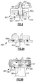
- FIG. 5 illustrates a clamp of an adjustable blade outer air seal apparatus.
- FIG. 6 illustrates a perspective view of the clamp of FIG. 5 .
- FIG. 7 illustrates another example adjustable blade outer air seal apparatus.
- FIG. 8 illustrates another adjustable blade outer air seal apparatus.
- FIG. 9A illustrates an example blade outer air seal apparatus in a compressor section of a gas turbine engine.
- FIG. 9B illustrates another cross-section of the adjustable blade outer air seal apparatus of FIG. 9A .
- FIG. 1 schematically illustrates a gas turbine engine 20 .
- the gas turbine engine 20 is disclosed herein as a two-spool turbofan that generally incorporates a fan section 22 , a compressor section 24 , a combustor section 26 and a turbine section 28 .
- Alternative engines might include an augmentor section (not shown) among other systems or features.
- the fan section 22 drives air along a bypass flowpath while the compressor section 24 drives air along a core flowpath for compression and communication into the combustor section 26 then expansion through the turbine section 28 .
- FIG. 1 schematically illustrates a gas turbine engine 20 .
- the gas turbine engine 20 is disclosed herein as a two-spool turbofan that generally incorporates a fan section 22 , a compressor section 24 , a combustor section 26 and a turbine section 28 .
- Alternative engines might include an augmentor section (not shown) among other systems or features.
- the fan section 22 drives air along a bypass flowpath while the compressor section 24 drives air along a core flow
- the engine 20 generally includes a low speed spool 30 and a high speed spool 32 mounted for rotation about an engine central longitudinal axis A relative to an engine static structure 36 via several bearing systems 38 . It should be understood that various bearing systems 38 at various locations may alternatively or additionally be provided.
- the low speed spool 30 generally includes an inner shaft 40 that interconnects a fan 42 , a low pressure compressor 44 and a low pressure turbine 46 .
- the inner shaft 40 is connected to the fan 42 through a gear assembly 48 to drive the fan 42 at a lower speed than the low speed spool 30 .
- the high speed spool 32 includes an outer shaft 50 that interconnects a high pressure compressor 52 and high pressure turbine 54 .
- a combustor 56 is arranged between the high pressure compressor 52 and the high pressure turbine 54 .
- the inner shaft 40 and the outer shaft 50 are concentric and rotate via bearing systems 38 about the engine central longitudinal axis A which is collinear with their longitudinal axes.
- the core airflow is compressed by the low pressure compressor 44 then the high pressure compressor 52 , mixed and burned with fuel in the combustor 56 , then expanded over the high pressure turbine 54 and low pressure turbine 46 .
- the turbines 46 , 54 rotationally drive the respective low speed spool 30 and high speed spool 32 in response to the expansion.
- the engine 20 in one example a high-bypass geared aircraft engine.
- the engine 20 bypass ratio is greater than about six (6), with an example embodiment being greater than ten (10)
- the gear assembly 48 is an epicyclic gear train, such as a planetary gear system or other gear system, with a gear reduction ratio of greater than about 2.3
- the low pressure turbine 46 has a pressure ratio that is greater than about 5.
- the engine 20 bypass ratio is greater than about ten (10:1)
- the fan diameter is significantly larger than that of the low pressure compressor 44
- the low pressure turbine 46 has a pressure ratio that is greater than about 5:1.
- Low pressure turbine 46 pressure ratio is pressure measured prior to inlet of low pressure turbine 46 as related to the pressure at the outlet of the low pressure turbine 46 prior to an exhaust nozzle.
- the gear assembly 48 may be an epicycle gear train, such as a planetary gear system or other gear system, with a gear reduction ratio of greater than about 2.5:1. It should be understood, however, that the above parameters are only exemplary of one embodiment of a geared architecture engine and that the present invention is applicable to other gas turbine engines including direct drive turbofans.
- the fan section 22 of the engine 20 is designed for a particular flight condition—typically cruise at about 0.8 Mach and about 35,000 feet.
- TSFC Thrust Specific Fuel Consumption
- Low fan pressure ratio is the pressure ratio across the fan blade alone, without a Fan Exit Guide Vane (“FEGV”) system.
- the low fan pressure ratio as disclosed herein according to one non-limiting embodiment is less than about 1.45.
- Low corrected fan tip speed is the actual fan tip speed in ft/sec divided by an industry standard temperature correction of [(Tambient deg R)/518.7) ⁇ 0.5].
- the “Low corrected fan tip speed” as disclosed herein according to one non-limiting embodiment is less than about 1150 ft/second.
- FIG. 2 schematically illustrates a cross-section through the turbine section 28 of the engine 20 , although the examples herein are also understood to be applicable to the compressor section 24 or other rotatable machinery.
- the engine 20 includes a case structure 70 that extends generally circumferentially around the axis A of the engine 20 .
- a support ring structure 72 is mounted radially inwards of the case structure 70 with regard to the axis A.
- at least one blade outer air seal segment 74 (one shown) is mounted relative to the support ring structure 72 . It is to be understood that a plurality of blade outer air seal segments 74 may be provided to form a complete annular shroud around central axis A.
- the at least one blade outer air seal segment 74 is radially adjustable relative to the support ring structure 72 , which provides the ability to directly adjust the radial position of the blade outer air seal segment 74 without having to indirectly adjust the position by moving the case structure 70 and/or support ring structure 72 .
- the support ring structure 72 is “floating” with regard to the case structure 70 . That is, the support ring structure 72 is non-rigidly connected with the case structure 70 using spring connections 76 .
- the spring connections 76 serve to center the support ring structure 72 relative to the case structure 70 and axis A. Thus, under certain load conditions, the support ring structure 72 is permitted to move relative to the case structure 70 .
- the blade outer air seal segments 74 are radially adjustable relative to the support ring structure 72 and are not rigidly affixed relative to the case structure 70 .
- this embodiment includes the “floating” arrangement, it is to be understood that other embodiments and the disclosed examples disclosed are not limited to a “floating” arrangement.
- FIG. 3 shows an example adjustable blade outer air seal apparatus 80 that incorporates the blade outer air seal segment 74 .
- the blade outer air seal segment 74 includes a lower body portion 82 that generally extends between a leading end 84 and a trailing end 86 , circumferential sides 88 (one shown) and a radially inner seal surface 90 .
- the seal surface 90 is a gas path surface that faces in a direction toward rotating blade B.
- the blade outer air seal segment 74 includes a threaded shaft 92 that extends radially outwardly from the lower body portion 82 .
- the threaded shaft 92 extends through an unthreaded opening 94 in the support ring structure 72 .
- a threaded portion 96 on the periphery of the upper part of the threaded shaft 92 threadingly engages an actuation arm 98 .
- the actuation arm 98 extends between a first end 98 a , which is threadingly engaged with the threaded portion 96 of the threaded shaft 92 , and a second end 98 b that is used to rotate the actuation arm 98 relative to radial axis C.
- the first end 98 a of the actuation arm 98 is secured between a clamp member 100 and a radially outer surface of the support ring structure 72 .
- an adjustable spacer 102 , seal bushing 104 and thrust plate 106 are provided between the first end 98 a of the actuation arm 98 and the radially outer surface of the support ring structure 72 .
- each actuation arm 98 of each blade outer air seal 74 includes a dedicated actuator, such as a motor.
- the actuation arms 98 are coupled to a common actuator through a unison ring, for example.
- a thread pitch of the threaded portion 96 of the threaded shaft 92 is selected such that for a given angular rotation of the actuation arm 98 , the blade outer air seal segment 74 moves a predetermined amount in a radial direction along axis C.
- the thread pitch is 28 threads per inch ( 11 threads per centimeter) such that approximately 10° rotation of the actuation arm 98 causes a radial position change of the blade outer air seal segment 74 of approximately 0.001 inches (0.00254 centimeters).
- the adjustable blade outer air seal apparatus 80 provides fine control of the radial position of the seal surface 90 .
- the position of the blade outer air seal segment 74 is radially adjusted in response to at least one of an aircraft maneuver and a detected engine temperature.
- an aircraft maneuver such as a change in aircraft pitch, can cause the engine 20 to deflect.
- the aircraft maneuver causes a control signal to be sent to the actuator or actuators to radially retract the blade out air seals 74 .
- a detected change temperature can cause thermal expansion or contraction in portions of the engine 20 .
- a control signal is sent to the actuator or actuators to radially move the blade out air seals 74 .
- the adjustable blade outer air seal apparatus 80 is able to rapidly respond to a signal to move.
- the blade outer air seals 74 are radially adjusted in a response time of less than one second between initiating a control signal to move and movement between radial positions.
- the adjustable spacer 102 is used to initially set the radial position of the blade outer air seal segment 74 .
- the adjustable spacer 102 has a radial dimension 102 a that is adjustable to control an initial radial position of the blade outer air seal segment 74 relative to the support ring structure 72 . That is, for a selected relatively smaller radial dimension 102 a , the initial position of the blade outer air seal segment 74 is relatively closer to axis A in along radial axis C. For a selected relatively larger radial dimension 102 a , the radial position of the blade outer air seal segment 74 is relatively farther from axis A along radial axis C.
- the adjustable spacer 102 is a stacked washer system. For example, greater or fewer number of washers are provided in the stack to adjust the radial dimension 102 a of the adjustable spacer 102 to set an initial radial position of the blade outer air seal segment 74 . In this manner, a user initially sets a desirable clearance R between the seal surface 90 and the tip of the rotating blade B and thereafter finely adjusts the clearance R using the actuation arm 98 .
- the adjustable spacer 102 is a shim that has predetermined radial dimension 102 a to set a desired initial radial position of the blade outer air seal segment 74 .
- the bushing 104 provides an air seal between the unthreaded opening 94 in the support ring structure 72 and the gas path surface provided by the seal surface 90 . Further, as the gas flowing over the blade B varies in pressure, the pressure variations are reacted through the blade outer air seal segment 74 into the thrust plate 106 . Thus, the thrust plate 106 facilitates load management in the adjustable blade outer air seal apparatus 80 .
- the blade outer air seal segment 74 optionally includes a cavity 108 that extends through the threaded shaft 92 and lower body portion 82 .
- the cavity 108 includes an end 108 a that opens at the seal surface 90 of the blade outer air seal segment 74 .
- a sensor probe 110 is received at least partially within the cavity 108 .
- the sensor probe 110 facilitates determining the clearance R.
- the sensor probe 110 includes an end 110 a that is flush with the seal surface 90 at the open end 108 a of the cavity 108 and the radial axis C along which the cavity 108 extends is centered with regard to the lower body portion 82 in order to gauge the blade outer air seal 74 position at the center.
- the sensor probe 110 is a laser sensor, microwave sensor, or other suitable type of sensor for use within a gas turbine engine environment.
- FIG. 4 a portion of another example threaded shaft 192 is shown.
- like reference numerals designate like elements where appropriate and reference numerals with the addition of one-hundred or multiples thereof designate modified elements that are understood to incorporate the same features and benefits of the corresponding elements.
- the threaded shaft 192 shown in FIG. 4 may be used in place of the threaded shaft 92 as shown in FIG. 3 .
- the threaded portion 196 of the threaded shaft 192 includes trapezoidal threads 196 a , also known as acme threads.
- the trapezoidal threads 196 a provide a high strength threaded connection between the threaded shaft 192 and the actuation arm 98 .
- FIGS. 5 and 6 schematically show selected portions of two neighboring adjustable blade outer air seal apparatuses 80 , as previously described.
- the clamp member 100 in this example is common between the neighboring adjustable blade outer air seal apparatuses 80 . That is, the clamp member 100 extends between at least two actuation arms 98 to clamp the respective first ends 98 a onto the support ring structure 72 .
- the common clamp member 100 is rigidly secured directly to the support ring structure 72 using fastener 100 a .
- the common clamp member 100 is shown as securing two actuator arms 98 in this example, it is to be understood that the clamp member 100 can alternatively be adapted to clamp a single actuation arm 98 or greater than two actuation arms 98 in other examples.
- FIG. 7 shows another example adjustable blade outer air seal apparatus 280 that is somewhat similar to the adjustable blade outer air seal apparatus 80 as described with reference to FIG. 3 .
- the blade outer air seal segment 74 and the threaded shaft 292 are integrally formed as a single, monolithic structure with the cavity 208 extending there through to end 208 a that is flush with a seal surface 290 of the blade outer air seal segment 274 .
- a sensor probe 210 is located at least partially within the cavity 208 such that an end 210 a of the sensor probe 210 is flush with the seal surface 290 .
- a retaining nut 210 b secures the sensor probe 210 relative to the blade outer air seal segment 274 .
- a threaded interface 210 c is provided between the retainer nut 210 b and the upper portion of the threaded shaft 292 .
- the adjustable blade outer air seal apparatus 280 includes an upper bushing 294 a located between the first and 98 a of the actuation arm 98 and clamp member 100 , and a lower bushing 294 b between the first end 98 a of the actuation arm 98 and the support ring structure 272 .
- an adjustable spacer 202 in this example is located between the lower bushing 294 b and the support ring structure 272 .
- the adjustable spacer 202 is provided over the lower bushing 294 b and between the lower bushing 294 b and the first end 98 a of the actuation arm 98 .
- the support ring structure 272 and blade outer air seal segment 274 are additionally provided with an anti-rotation feature 290 a located the leading end 284 , the trailing end 286 or both.
- the anti-rotation feature 290 a includes a tab 290 b extending circumferentially and a slot 290 c that inter-fit to limit rotational movement about radial axis C.
- the tab 290 b is provided on the blade outer air seal segment 274 and a slot 290 c is provided in the support ring structure 272 , however, it is to be understood that the tab 290 b can alternatively be provided on the support ring structure 272 and a slot 290 c on the blade outer air seal segment 274 .
- FIG. 8 illustrates another embodiment of an adjustable blade air seal apparatus 380 .
- the threaded shaft 392 and the lower body portion 382 of the blade outer air seal segment 374 are non-integral.
- the lower body portion 382 of the blade outer air seal segment 74 includes a boss 382 a for connection with the threaded shaft 392 .
- the boss 382 a is integrally formed with the lower body portion 382 .
- the boss 382 a is a separate piece that is affixed, such as by welding, to the lower body portion 382 .
- the threaded portion 396 of the threaded shaft 392 is received into the boss 382 a and engages a corresponding threaded portion 382 b of the boss 382 a . Rotation of the threaded shaft 392 thereby causes movement of the lower body portion 382 .
- a splined connection 399 is provided between the first end 398 a and an upper portion of the threaded shaft 392 .
- the splined connection 399 allows the first end 398 a of the actuation arm 398 to be slid onto the threaded shaft 392 and rotate the shaft with regard to axis C. The rotation of the threaded shaft 392 moves the lower body portion 382 of the blade outer air seal segment 374 through the threaded engagement with the boss 382 a.
- FIGS. 9A and 9B illustrate cross-sections of selected portions of another example adjustable blade outer air seal apparatus 480 used in the compressor section 24 .
- the blade outer air seal segment 474 and support ring structure 472 include a seal 491 .
- the seal 491 limits gas leakage around the blade outer air seal segment 474 through cavity P from the trailing end 486 back to the leading end 484 .
- the seal limits flow of relatively higher pressure gas that is already passed over the blade B around the blade outer air seal segment 474 back to an upstream position at the leading end 484 .
Landscapes
- Engineering & Computer Science (AREA)
- Mechanical Engineering (AREA)
- General Engineering & Computer Science (AREA)
- Structures Of Non-Positive Displacement Pumps (AREA)
- Chemical & Material Sciences (AREA)
- Combustion & Propulsion (AREA)
Abstract
Description
Claims (21)
Priority Applications (6)
| Application Number | Priority Date | Filing Date | Title |
|---|---|---|---|
| US13/396,016 US9228447B2 (en) | 2012-02-14 | 2012-02-14 | Adjustable blade outer air seal apparatus |
| PCT/US2013/026117 WO2013123172A1 (en) | 2012-02-14 | 2013-02-14 | Adjustable blade outer air seal apparatus |
| EP13749712.9A EP2815082B1 (en) | 2012-02-14 | 2013-02-14 | Adjustable blade outer air seal apparatus |
| SG11201404091VA SG11201404091VA (en) | 2012-02-14 | 2013-02-14 | Adjustable blade outer air seal apparatus |
| US14/749,695 US10280784B2 (en) | 2012-02-14 | 2015-06-25 | Adjustable blade outer air seal apparatus |
| US16/166,279 US10822989B2 (en) | 2012-02-14 | 2018-10-22 | Adjustable blade outer air seal apparatus |
Applications Claiming Priority (1)
| Application Number | Priority Date | Filing Date | Title |
|---|---|---|---|
| US13/396,016 US9228447B2 (en) | 2012-02-14 | 2012-02-14 | Adjustable blade outer air seal apparatus |
Related Child Applications (1)
| Application Number | Title | Priority Date | Filing Date |
|---|---|---|---|
| US14/749,695 Continuation US10280784B2 (en) | 2012-02-14 | 2015-06-25 | Adjustable blade outer air seal apparatus |
Publications (2)
| Publication Number | Publication Date |
|---|---|
| US20130209240A1 US20130209240A1 (en) | 2013-08-15 |
| US9228447B2 true US9228447B2 (en) | 2016-01-05 |
Family
ID=48945690
Family Applications (3)
| Application Number | Title | Priority Date | Filing Date |
|---|---|---|---|
| US13/396,016 Active 2034-08-02 US9228447B2 (en) | 2012-02-14 | 2012-02-14 | Adjustable blade outer air seal apparatus |
| US14/749,695 Active 2033-12-29 US10280784B2 (en) | 2012-02-14 | 2015-06-25 | Adjustable blade outer air seal apparatus |
| US16/166,279 Active 2032-05-27 US10822989B2 (en) | 2012-02-14 | 2018-10-22 | Adjustable blade outer air seal apparatus |
Family Applications After (2)
| Application Number | Title | Priority Date | Filing Date |
|---|---|---|---|
| US14/749,695 Active 2033-12-29 US10280784B2 (en) | 2012-02-14 | 2015-06-25 | Adjustable blade outer air seal apparatus |
| US16/166,279 Active 2032-05-27 US10822989B2 (en) | 2012-02-14 | 2018-10-22 | Adjustable blade outer air seal apparatus |
Country Status (4)
| Country | Link |
|---|---|
| US (3) | US9228447B2 (en) |
| EP (1) | EP2815082B1 (en) |
| SG (1) | SG11201404091VA (en) |
| WO (1) | WO2013123172A1 (en) |
Cited By (25)
| Publication number | Priority date | Publication date | Assignee | Title |
|---|---|---|---|---|
| US20150377050A1 (en) * | 2014-06-27 | 2015-12-31 | Rolls-Royce Corporation | Turbine shroud with sealed blade track |
| US20160356170A1 (en) * | 2013-09-27 | 2016-12-08 | United Technologies Corporation | Gas turbine engine rapid response clearance control system |
| US9945256B2 (en) | 2014-06-27 | 2018-04-17 | Rolls-Royce Corporation | Segmented turbine shroud with seals |
| US10107129B2 (en) | 2016-03-16 | 2018-10-23 | United Technologies Corporation | Blade outer air seal with spring centering |
| US10132184B2 (en) | 2016-03-16 | 2018-11-20 | United Technologies Corporation | Boas spring loaded rail shield |
| US10138749B2 (en) | 2016-03-16 | 2018-11-27 | United Technologies Corporation | Seal anti-rotation feature |
| US10138750B2 (en) | 2016-03-16 | 2018-11-27 | United Technologies Corporation | Boas segmented heat shield |
| US10161258B2 (en) | 2016-03-16 | 2018-12-25 | United Technologies Corporation | Boas rail shield |
| US10190429B2 (en) | 2016-04-29 | 2019-01-29 | Stein Seal Company | Intershaft seal with asymmetric sealing ring and centrifugal retaining plates |
| US10337346B2 (en) | 2016-03-16 | 2019-07-02 | United Technologies Corporation | Blade outer air seal with flow guide manifold |
| US10415414B2 (en) | 2016-03-16 | 2019-09-17 | United Technologies Corporation | Seal arc segment with anti-rotation feature |
| US10422241B2 (en) | 2016-03-16 | 2019-09-24 | United Technologies Corporation | Blade outer air seal support for a gas turbine engine |
| US10422240B2 (en) | 2016-03-16 | 2019-09-24 | United Technologies Corporation | Turbine engine blade outer air seal with load-transmitting cover plate |
| US20190301296A1 (en) * | 2018-03-27 | 2019-10-03 | Rolls-Royce North American Technologies Inc. | Full hoop blade track with keystoning segments |
| US10443616B2 (en) | 2016-03-16 | 2019-10-15 | United Technologies Corporation | Blade outer air seal with centrally mounted seal arc segments |
| US10443424B2 (en) | 2016-03-16 | 2019-10-15 | United Technologies Corporation | Turbine engine blade outer air seal with load-transmitting carriage |
| US10450882B2 (en) | 2016-03-22 | 2019-10-22 | United Technologies Corporation | Anti-rotation shim seal |
| US10513943B2 (en) | 2016-03-16 | 2019-12-24 | United Technologies Corporation | Boas enhanced heat transfer surface |
| US10563531B2 (en) | 2016-03-16 | 2020-02-18 | United Technologies Corporation | Seal assembly for gas turbine engine |
| US10822964B2 (en) | 2018-11-13 | 2020-11-03 | Raytheon Technologies Corporation | Blade outer air seal with non-linear response |
| US10920618B2 (en) | 2018-11-19 | 2021-02-16 | Raytheon Technologies Corporation | Air seal interface with forward engagement features and active clearance control for a gas turbine engine |
| US10934941B2 (en) | 2018-11-19 | 2021-03-02 | Raytheon Technologies Corporation | Air seal interface with AFT engagement features and active clearance control for a gas turbine engine |
| US10975721B2 (en) | 2016-01-12 | 2021-04-13 | Pratt & Whitney Canada Corp. | Cooled containment case using internal plenum |
| US11105338B2 (en) | 2016-05-26 | 2021-08-31 | Rolls-Royce Corporation | Impeller shroud with slidable coupling for clearance control in a centrifugal compressor |
| US11225880B1 (en) | 2017-02-22 | 2022-01-18 | Rolls-Royce Corporation | Turbine shroud ring for a gas turbine engine having a tip clearance probe |
Families Citing this family (18)
| Publication number | Priority date | Publication date | Assignee | Title |
|---|---|---|---|---|
| WO2014186015A2 (en) * | 2013-03-11 | 2014-11-20 | United Technologies Corporation | Actuator for gas turbine engine blade outer air seal |
| EP3044425B1 (en) * | 2013-09-11 | 2021-03-10 | United Technologies Corporation | Blade outer air seal having angled retention hook |
| US10316685B2 (en) | 2013-10-04 | 2019-06-11 | United Technologies Corporation | Gas turbine engine ramped rapid response clearance control system |
| WO2015094622A1 (en) * | 2013-12-17 | 2015-06-25 | United Technologies Corporation | Turbomachine blade clearance control system |
| JP6436639B2 (en) * | 2014-03-27 | 2018-12-12 | 三菱日立パワーシステムズ株式会社 | Rotating machine and rotating machine control method |
| US10047624B2 (en) * | 2015-06-29 | 2018-08-14 | Rolls-Royce North American Technologies Inc. | Turbine shroud segment with flange-facing perimeter seal |
| US10196919B2 (en) | 2015-06-29 | 2019-02-05 | Rolls-Royce North American Technologies Inc. | Turbine shroud segment with load distribution springs |
| US10094234B2 (en) | 2015-06-29 | 2018-10-09 | Rolls-Royce North America Technologies Inc. | Turbine shroud segment with buffer air seal system |
| GB201518131D0 (en) * | 2015-10-14 | 2015-11-25 | Rolls Royce Plc | Shroud assembly for a gas turbine engine |
| US10316686B2 (en) * | 2015-12-04 | 2019-06-11 | United Technologies Corporation | High response turbine tip clearance control system |
| US10280799B2 (en) | 2016-06-10 | 2019-05-07 | United Technologies Corporation | Blade outer air seal assembly with positioning feature for gas turbine engine |
| DE102017211316A1 (en) * | 2017-07-04 | 2019-01-10 | MTU Aero Engines AG | Turbomachinery sealing ring |
| US11015665B2 (en) * | 2018-01-24 | 2021-05-25 | Hamilton Sunstrand Corporation | Proportional control brake |
| US10704408B2 (en) * | 2018-05-03 | 2020-07-07 | Rolls-Royce North American Technologies Inc. | Dual response blade track system |
| US11913343B2 (en) * | 2019-10-03 | 2024-02-27 | Rtx Corporation | Replaceable rotor blade tip clearance measurement device for a gas turbine engine |
| US11131207B1 (en) * | 2020-05-01 | 2021-09-28 | Raytheon Technologies Corporation | Semi-autonomous rapid response active clearance control system |
| US20220178266A1 (en) * | 2020-12-04 | 2022-06-09 | General Electric Company | Fast response active clearance control system with piezoelectric actuator |
| US11655724B1 (en) | 2022-04-25 | 2023-05-23 | General Electric Company | Clearance control of fan blades in a gas turbine engine |
Citations (38)
| Publication number | Priority date | Publication date | Assignee | Title |
|---|---|---|---|---|
| US2616257A (en) | 1946-01-09 | 1952-11-04 | Bendix Aviat Corp | Combustion chamber with air inlet means providing a plurality of concentric strata of varying velocities |
| US3227418A (en) | 1963-11-04 | 1966-01-04 | Gen Electric | Variable clearance seal |
| US4330234A (en) * | 1979-02-20 | 1982-05-18 | Rolls-Royce Limited | Rotor tip clearance control apparatus for a gas turbine engine |
| US4334822A (en) * | 1979-06-06 | 1982-06-15 | Mtu Motoren- Und Turbinen-Union Munchen Gmbh | Circumferential gap seal for axial-flow machines |
| US5049033A (en) | 1990-02-20 | 1991-09-17 | General Electric Company | Blade tip clearance control apparatus using cam-actuated shroud segment positioning mechanism |
| US5056988A (en) * | 1990-02-12 | 1991-10-15 | General Electric Company | Blade tip clearance control apparatus using shroud segment position modulation |
| US5096375A (en) | 1989-09-08 | 1992-03-17 | General Electric Company | Radial adjustment mechanism for blade tip clearance control apparatus |
| US5104287A (en) | 1989-09-08 | 1992-04-14 | General Electric Company | Blade tip clearance control apparatus for a gas turbine engine |
| US5129231A (en) | 1990-03-12 | 1992-07-14 | United Technologies Corporation | Cooled combustor dome heatshield |
| US5203673A (en) * | 1992-01-21 | 1993-04-20 | Westinghouse Electric Corp. | Tip clearance control apparatus for a turbo-machine blade |
| US5253471A (en) | 1990-08-16 | 1993-10-19 | Rolls-Royce Plc | Gas turbine engine combustor |
| US5307637A (en) | 1992-07-09 | 1994-05-03 | General Electric Company | Angled multi-hole film cooled single wall combustor dome plate |
| US5419115A (en) | 1994-04-29 | 1995-05-30 | United Technologies Corporation | Bulkhead and fuel nozzle guide assembly for an annular combustion chamber |
| US5479774A (en) | 1991-04-30 | 1996-01-02 | Rolls-Royce Plc | Combustion chamber assembly in a gas turbine engine |
| US5623827A (en) | 1995-01-26 | 1997-04-29 | General Electric Company | Regenerative cooled dome assembly for a gas turbine engine combustor |
| US5791872A (en) * | 1997-04-22 | 1998-08-11 | Rolls-Royce Inc. | Blade tip clearence control apparatus |
| US5818242A (en) * | 1996-05-08 | 1998-10-06 | United Technologies Corporation | Microwave recess distance and air-path clearance sensor |
| US5956955A (en) | 1994-08-01 | 1999-09-28 | Bmw Rolls-Royce Gmbh | Heat shield for a gas turbine combustion chamber |
| US6037581A (en) * | 1996-01-15 | 2000-03-14 | Siemens Aktiengesellschaft | Device for recording a change in position at a turbine configuration |
| US6997673B2 (en) | 2003-12-11 | 2006-02-14 | Honeywell International, Inc. | Gas turbine high temperature turbine blade outer air seal assembly |
| US20060042257A1 (en) | 2004-08-27 | 2006-03-02 | Pratt & Whitney Canada Corp. | Combustor heat shield and method of cooling |
| US20060140754A1 (en) * | 2004-12-27 | 2006-06-29 | Mitsubishi Heavy Industries, Ltd. | Gas turbine |
| US7079957B2 (en) | 2003-12-30 | 2006-07-18 | General Electric Company | Method and system for active tip clearance control in turbines |
| US20070082530A1 (en) | 2005-10-07 | 2007-04-12 | Burd Steven W | Gas turbine combustor bulkhead panel |
| US7259552B2 (en) * | 2002-05-31 | 2007-08-21 | Siemens Power Generation, Inc. | Wear monitor for turbo-machine |
| US20090128166A1 (en) | 2007-11-21 | 2009-05-21 | Rolls-Royce Plc | Apparatus to measure the clearance between a first component and a second component |
| EP2090754A2 (en) | 2008-02-18 | 2009-08-19 | United Technologies Corporation | Gas turbine engines and methods involving blade outer air seals |
| WO2009130262A1 (en) | 2008-04-23 | 2009-10-29 | Abb Turbo Systems Ag | Carrier ring of a conducting device with sealing air channel |
| US7625169B2 (en) * | 2005-07-02 | 2009-12-01 | Rolls-Royce Plc | Variable displacement turbine liner |
| US7694505B2 (en) | 2006-07-31 | 2010-04-13 | General Electric Company | Gas turbine engine assembly and method of assembling same |
| US20100209231A1 (en) | 2009-02-16 | 2010-08-19 | Rolls-Royce Plc | Combination of mechanical actuator and case cooling apparatus |
| US20100303612A1 (en) * | 2009-05-26 | 2010-12-02 | General Electric Company | System and method for clearance control |
| US20110044801A1 (en) | 2009-08-18 | 2011-02-24 | Pratt & Whitney Canada Corp. | Blade outer air seal cooling |
| US8011883B2 (en) | 2004-12-29 | 2011-09-06 | United Technologies Corporation | Gas turbine engine blade tip clearance apparatus and method |
| US20120057958A1 (en) * | 2009-05-28 | 2012-03-08 | Hermann Klingels | Clearance control system, turbomachine and method for adjusting a running clearance between a rotor and a casing of a turbomachine |
| US8177483B2 (en) | 2009-05-22 | 2012-05-15 | General Electric Company | Active casing alignment control system and method |
| US8475110B2 (en) * | 2009-07-30 | 2013-07-02 | General Electric Company | System and method for online monitoring of corrosion of gas turbine components |
| US8558538B2 (en) * | 2008-09-29 | 2013-10-15 | Rosemount Aerospace Inc. | Blade tip clearance measurement sensor for gas turbine engines |
Family Cites Families (18)
| Publication number | Priority date | Publication date | Assignee | Title |
|---|---|---|---|---|
| US2947364A (en) * | 1955-01-25 | 1960-08-02 | Rolls Royce | Propeller-driving compound gas-turbine engine for aircraft |
| US4576548A (en) * | 1984-01-17 | 1986-03-18 | Westinghouse Electric Corp. | Self-aligning static seal for gas turbine stator vanes |
| US5639210A (en) * | 1995-10-23 | 1997-06-17 | United Technologies Corporation | Rotor blade outer tip seal apparatus |
| US6547522B2 (en) * | 2001-06-18 | 2003-04-15 | General Electric Company | Spring-backed abradable seal for turbomachinery |
| US6840519B2 (en) * | 2001-10-30 | 2005-01-11 | General Electric Company | Actuating mechanism for a turbine and method of retrofitting |
| US6786487B2 (en) * | 2001-12-05 | 2004-09-07 | General Electric Company | Actuated brush seal |
| US6572115B1 (en) * | 2001-12-21 | 2003-06-03 | General Electric Company | Actuating seal for a rotary machine and method of retrofitting |
| US7435049B2 (en) * | 2004-03-30 | 2008-10-14 | General Electric Company | Sealing device and method for turbomachinery |
| US7229246B2 (en) * | 2004-09-30 | 2007-06-12 | General Electric Company | Compliant seal and system and method thereof |
| US7704041B2 (en) * | 2006-04-07 | 2010-04-27 | General Electric Company | Variable clearance positive pressure packing ring and carrier arrangement with coil type spring |
| US7419164B2 (en) * | 2006-08-15 | 2008-09-02 | General Electric Company | Compliant plate seals for turbomachinery |
| DE102006038753A1 (en) * | 2006-08-17 | 2008-03-13 | Mtu Aero Engines Gmbh | Arrangement for running gap optimization for turbomachines |
| US7748945B2 (en) * | 2006-12-07 | 2010-07-06 | Jerry Wayne Johnson | Floating sealing ring |
| US20100078893A1 (en) * | 2008-09-30 | 2010-04-01 | General Electric Company | Active retractable seal for turbomachinery and related method |
| DE102009023061A1 (en) * | 2009-05-28 | 2010-12-02 | Mtu Aero Engines Gmbh | Gap control system, turbomachine and method for adjusting a running gap between a rotor and a casing of a turbomachine |
| GB0914679D0 (en) * | 2009-08-24 | 2009-09-30 | Rolls Royce Plc | Adjustable fan case liner and mounting method |
| EP2386726B1 (en) * | 2010-05-12 | 2012-10-31 | Siemens Aktiengesellschaft | Channel wall section for a ring-shaped flow channel of an axial turbomaschine with blade tip gap adjustment, corresponding axial compressor and gas turbine |
| US8944756B2 (en) * | 2011-07-15 | 2015-02-03 | United Technologies Corporation | Blade outer air seal assembly |
-
2012
- 2012-02-14 US US13/396,016 patent/US9228447B2/en active Active
-
2013
- 2013-02-14 EP EP13749712.9A patent/EP2815082B1/en active Active
- 2013-02-14 WO PCT/US2013/026117 patent/WO2013123172A1/en active Application Filing
- 2013-02-14 SG SG11201404091VA patent/SG11201404091VA/en unknown
-
2015
- 2015-06-25 US US14/749,695 patent/US10280784B2/en active Active
-
2018
- 2018-10-22 US US16/166,279 patent/US10822989B2/en active Active
Patent Citations (41)
| Publication number | Priority date | Publication date | Assignee | Title |
|---|---|---|---|---|
| US2616257A (en) | 1946-01-09 | 1952-11-04 | Bendix Aviat Corp | Combustion chamber with air inlet means providing a plurality of concentric strata of varying velocities |
| US3227418A (en) | 1963-11-04 | 1966-01-04 | Gen Electric | Variable clearance seal |
| US4330234A (en) * | 1979-02-20 | 1982-05-18 | Rolls-Royce Limited | Rotor tip clearance control apparatus for a gas turbine engine |
| US4334822A (en) * | 1979-06-06 | 1982-06-15 | Mtu Motoren- Und Turbinen-Union Munchen Gmbh | Circumferential gap seal for axial-flow machines |
| US5096375A (en) | 1989-09-08 | 1992-03-17 | General Electric Company | Radial adjustment mechanism for blade tip clearance control apparatus |
| US5104287A (en) | 1989-09-08 | 1992-04-14 | General Electric Company | Blade tip clearance control apparatus for a gas turbine engine |
| US5056988A (en) * | 1990-02-12 | 1991-10-15 | General Electric Company | Blade tip clearance control apparatus using shroud segment position modulation |
| US5049033A (en) | 1990-02-20 | 1991-09-17 | General Electric Company | Blade tip clearance control apparatus using cam-actuated shroud segment positioning mechanism |
| US5129231A (en) | 1990-03-12 | 1992-07-14 | United Technologies Corporation | Cooled combustor dome heatshield |
| US5253471A (en) | 1990-08-16 | 1993-10-19 | Rolls-Royce Plc | Gas turbine engine combustor |
| US5479774A (en) | 1991-04-30 | 1996-01-02 | Rolls-Royce Plc | Combustion chamber assembly in a gas turbine engine |
| US5203673A (en) * | 1992-01-21 | 1993-04-20 | Westinghouse Electric Corp. | Tip clearance control apparatus for a turbo-machine blade |
| US5307637A (en) | 1992-07-09 | 1994-05-03 | General Electric Company | Angled multi-hole film cooled single wall combustor dome plate |
| US5419115A (en) | 1994-04-29 | 1995-05-30 | United Technologies Corporation | Bulkhead and fuel nozzle guide assembly for an annular combustion chamber |
| US5956955A (en) | 1994-08-01 | 1999-09-28 | Bmw Rolls-Royce Gmbh | Heat shield for a gas turbine combustion chamber |
| US5623827A (en) | 1995-01-26 | 1997-04-29 | General Electric Company | Regenerative cooled dome assembly for a gas turbine engine combustor |
| US6037581A (en) * | 1996-01-15 | 2000-03-14 | Siemens Aktiengesellschaft | Device for recording a change in position at a turbine configuration |
| US5818242A (en) * | 1996-05-08 | 1998-10-06 | United Technologies Corporation | Microwave recess distance and air-path clearance sensor |
| US5791872A (en) * | 1997-04-22 | 1998-08-11 | Rolls-Royce Inc. | Blade tip clearence control apparatus |
| US7259552B2 (en) * | 2002-05-31 | 2007-08-21 | Siemens Power Generation, Inc. | Wear monitor for turbo-machine |
| US6997673B2 (en) | 2003-12-11 | 2006-02-14 | Honeywell International, Inc. | Gas turbine high temperature turbine blade outer air seal assembly |
| US7079957B2 (en) | 2003-12-30 | 2006-07-18 | General Electric Company | Method and system for active tip clearance control in turbines |
| US20060042257A1 (en) | 2004-08-27 | 2006-03-02 | Pratt & Whitney Canada Corp. | Combustor heat shield and method of cooling |
| US7207769B2 (en) * | 2004-12-27 | 2007-04-24 | Mitsubishi Heavy Industries, Ltd. | Gas turbine |
| US20060140754A1 (en) * | 2004-12-27 | 2006-06-29 | Mitsubishi Heavy Industries, Ltd. | Gas turbine |
| US8011883B2 (en) | 2004-12-29 | 2011-09-06 | United Technologies Corporation | Gas turbine engine blade tip clearance apparatus and method |
| US7625169B2 (en) * | 2005-07-02 | 2009-12-01 | Rolls-Royce Plc | Variable displacement turbine liner |
| US20070082530A1 (en) | 2005-10-07 | 2007-04-12 | Burd Steven W | Gas turbine combustor bulkhead panel |
| US7694505B2 (en) | 2006-07-31 | 2010-04-13 | General Electric Company | Gas turbine engine assembly and method of assembling same |
| US20090128166A1 (en) | 2007-11-21 | 2009-05-21 | Rolls-Royce Plc | Apparatus to measure the clearance between a first component and a second component |
| EP2090754A2 (en) | 2008-02-18 | 2009-08-19 | United Technologies Corporation | Gas turbine engines and methods involving blade outer air seals |
| US20090208322A1 (en) | 2008-02-18 | 2009-08-20 | United Technologies Corp. | Gas turbine engine systems and methods involving blade outer air seals |
| WO2009130262A1 (en) | 2008-04-23 | 2009-10-29 | Abb Turbo Systems Ag | Carrier ring of a conducting device with sealing air channel |
| US8558538B2 (en) * | 2008-09-29 | 2013-10-15 | Rosemount Aerospace Inc. | Blade tip clearance measurement sensor for gas turbine engines |
| US20100209231A1 (en) | 2009-02-16 | 2010-08-19 | Rolls-Royce Plc | Combination of mechanical actuator and case cooling apparatus |
| US8177483B2 (en) | 2009-05-22 | 2012-05-15 | General Electric Company | Active casing alignment control system and method |
| US20100303612A1 (en) * | 2009-05-26 | 2010-12-02 | General Electric Company | System and method for clearance control |
| US20120057958A1 (en) * | 2009-05-28 | 2012-03-08 | Hermann Klingels | Clearance control system, turbomachine and method for adjusting a running clearance between a rotor and a casing of a turbomachine |
| US8475110B2 (en) * | 2009-07-30 | 2013-07-02 | General Electric Company | System and method for online monitoring of corrosion of gas turbine components |
| US20110044801A1 (en) | 2009-08-18 | 2011-02-24 | Pratt & Whitney Canada Corp. | Blade outer air seal cooling |
| US20110044803A1 (en) | 2009-08-18 | 2011-02-24 | Pratt & Whitney Canada Corp. | Blade outer air seal anti-rotation |
Non-Patent Citations (4)
| Title |
|---|
| Gunston: "Jane's Aero-Engines," Pratt & Whitney/USA, Mar. 2000, JAEng-Issue 7, Copyright 2000 by Jane's Information Group Limited, pp. 510-512. |
| International Preliminary Report on Patentability for PCT Application No. PCT/US2013/026117 mailed Aug. 28, 2014. |
| International Search Report and Written Opinion for International Application No. PCT/US2013/026117 completed on May 27, 2013. |
| Singapore Search Report regarding Singapore Application No. 11201404091V. |
Cited By (32)
| Publication number | Priority date | Publication date | Assignee | Title |
|---|---|---|---|---|
| US10301961B2 (en) * | 2013-09-27 | 2019-05-28 | United Technologies Corporation | Gas turbine engine rapid response clearance control system |
| US20160356170A1 (en) * | 2013-09-27 | 2016-12-08 | United Technologies Corporation | Gas turbine engine rapid response clearance control system |
| US9938846B2 (en) * | 2014-06-27 | 2018-04-10 | Rolls-Royce North American Technologies Inc. | Turbine shroud with sealed blade track |
| US9945256B2 (en) | 2014-06-27 | 2018-04-17 | Rolls-Royce Corporation | Segmented turbine shroud with seals |
| US20150377050A1 (en) * | 2014-06-27 | 2015-12-31 | Rolls-Royce Corporation | Turbine shroud with sealed blade track |
| US10975721B2 (en) | 2016-01-12 | 2021-04-13 | Pratt & Whitney Canada Corp. | Cooled containment case using internal plenum |
| US10436053B2 (en) | 2016-03-16 | 2019-10-08 | United Technologies Corporation | Seal anti-rotation feature |
| US10422241B2 (en) | 2016-03-16 | 2019-09-24 | United Technologies Corporation | Blade outer air seal support for a gas turbine engine |
| US10161258B2 (en) | 2016-03-16 | 2018-12-25 | United Technologies Corporation | Boas rail shield |
| US11401827B2 (en) | 2016-03-16 | 2022-08-02 | Raytheon Technologies Corporation | Method of manufacturing BOAS enhanced heat transfer surface |
| US10138749B2 (en) | 2016-03-16 | 2018-11-27 | United Technologies Corporation | Seal anti-rotation feature |
| US10337346B2 (en) | 2016-03-16 | 2019-07-02 | United Technologies Corporation | Blade outer air seal with flow guide manifold |
| US10415414B2 (en) | 2016-03-16 | 2019-09-17 | United Technologies Corporation | Seal arc segment with anti-rotation feature |
| US10738643B2 (en) | 2016-03-16 | 2020-08-11 | Raytheon Technologies Corporation | Boas segmented heat shield |
| US10422240B2 (en) | 2016-03-16 | 2019-09-24 | United Technologies Corporation | Turbine engine blade outer air seal with load-transmitting cover plate |
| US10107129B2 (en) | 2016-03-16 | 2018-10-23 | United Technologies Corporation | Blade outer air seal with spring centering |
| US10132184B2 (en) | 2016-03-16 | 2018-11-20 | United Technologies Corporation | Boas spring loaded rail shield |
| US10443616B2 (en) | 2016-03-16 | 2019-10-15 | United Technologies Corporation | Blade outer air seal with centrally mounted seal arc segments |
| US10443424B2 (en) | 2016-03-16 | 2019-10-15 | United Technologies Corporation | Turbine engine blade outer air seal with load-transmitting carriage |
| US10138750B2 (en) | 2016-03-16 | 2018-11-27 | United Technologies Corporation | Boas segmented heat shield |
| US10513943B2 (en) | 2016-03-16 | 2019-12-24 | United Technologies Corporation | Boas enhanced heat transfer surface |
| US10563531B2 (en) | 2016-03-16 | 2020-02-18 | United Technologies Corporation | Seal assembly for gas turbine engine |
| US10450882B2 (en) | 2016-03-22 | 2019-10-22 | United Technologies Corporation | Anti-rotation shim seal |
| US10190429B2 (en) | 2016-04-29 | 2019-01-29 | Stein Seal Company | Intershaft seal with asymmetric sealing ring and centrifugal retaining plates |
| US11105338B2 (en) | 2016-05-26 | 2021-08-31 | Rolls-Royce Corporation | Impeller shroud with slidable coupling for clearance control in a centrifugal compressor |
| US11225880B1 (en) | 2017-02-22 | 2022-01-18 | Rolls-Royce Corporation | Turbine shroud ring for a gas turbine engine having a tip clearance probe |
| US10697315B2 (en) * | 2018-03-27 | 2020-06-30 | Rolls-Royce North American Technologies Inc. | Full hoop blade track with keystoning segments |
| US20190301296A1 (en) * | 2018-03-27 | 2019-10-03 | Rolls-Royce North American Technologies Inc. | Full hoop blade track with keystoning segments |
| US10822964B2 (en) | 2018-11-13 | 2020-11-03 | Raytheon Technologies Corporation | Blade outer air seal with non-linear response |
| US10920618B2 (en) | 2018-11-19 | 2021-02-16 | Raytheon Technologies Corporation | Air seal interface with forward engagement features and active clearance control for a gas turbine engine |
| US10934941B2 (en) | 2018-11-19 | 2021-03-02 | Raytheon Technologies Corporation | Air seal interface with AFT engagement features and active clearance control for a gas turbine engine |
| US11339722B2 (en) | 2018-11-19 | 2022-05-24 | Raytheon Technologies Corporation | Air seal interface with AFT engagement features and active clearance control for a gas turbine engine |
Also Published As
| Publication number | Publication date |
|---|---|
| US10280784B2 (en) | 2019-05-07 |
| US20190120076A1 (en) | 2019-04-25 |
| EP2815082A1 (en) | 2014-12-24 |
| EP2815082B1 (en) | 2019-02-13 |
| US10822989B2 (en) | 2020-11-03 |
| EP2815082A4 (en) | 2015-11-11 |
| US20160032754A1 (en) | 2016-02-04 |
| US20130209240A1 (en) | 2013-08-15 |
| WO2013123172A1 (en) | 2013-08-22 |
| SG11201404091VA (en) | 2014-09-26 |
Similar Documents
| Publication | Publication Date | Title |
|---|---|---|
| US10822989B2 (en) | Adjustable blade outer air seal apparatus | |
| US11022002B2 (en) | Attachment body for blade outer air seal | |
| US10655499B2 (en) | Flexible preloaded ball bearing assembly | |
| EP3112606B1 (en) | A seal for a gas turbine engine | |
| US10563672B2 (en) | Gas turbine engine compressor | |
| US11199102B2 (en) | Hydrostatic seal with increased design space | |
| US10746049B2 (en) | Gas turbine engine case including bearing compartment | |
| EP2998522B1 (en) | Gas turbine engine variable stator vane | |
| US11092030B2 (en) | Adaptive case for a gas turbine engine | |
| US20190017408A1 (en) | Gas turbine engine variable vane end wall insert | |
| US11674402B2 (en) | Hydrostatic seal with non-parallel beams for anti-tipping | |
| US20160097291A1 (en) | Stator assembly for a gas turbine engine | |
| US9051847B2 (en) | Floating segmented seal | |
| US20160208629A1 (en) | Anti-rotation vane | |
| EP3232017B1 (en) | Nacelle deflection measurement assembly | |
| US9869195B2 (en) | Support assembly for a gas turbine engine | |
| EP3095967B1 (en) | Support assembly for a gas turbine engine | |
| US10954861B2 (en) | Seal for a gas turbine engine | |
| US10815820B2 (en) | Integral shear locking bumper for gas turbine engine | |
| EP3611347B1 (en) | Gas turbine engine with stator segments | |
| EP3495621B1 (en) | Support ring for a gas turbine engine |
Legal Events
| Date | Code | Title | Description |
|---|---|---|---|
| AS | Assignment |
Owner name: UNITED TECHNOLOGIES CORPORATION, CONNECTICUT Free format text: ASSIGNMENT OF ASSIGNORS INTEREST;ASSIGNOR:MCCAFFREY, MICHAEL G.;REEL/FRAME:027701/0733 Effective date: 20120130 |
|
| STCF | Information on status: patent grant |
Free format text: PATENTED CASE |
|
| MAFP | Maintenance fee payment |
Free format text: PAYMENT OF MAINTENANCE FEE, 4TH YEAR, LARGE ENTITY (ORIGINAL EVENT CODE: M1551); ENTITY STATUS OF PATENT OWNER: LARGE ENTITY Year of fee payment: 4 |
|
| AS | Assignment |
Owner name: RAYTHEON TECHNOLOGIES CORPORATION, MASSACHUSETTS Free format text: CHANGE OF NAME;ASSIGNOR:UNITED TECHNOLOGIES CORPORATION;REEL/FRAME:054062/0001 Effective date: 20200403 |
|
| AS | Assignment |
Owner name: RAYTHEON TECHNOLOGIES CORPORATION, CONNECTICUT Free format text: CORRECTIVE ASSIGNMENT TO CORRECT THE AND REMOVE PATENT APPLICATION NUMBER 11886281 AND ADD PATENT APPLICATION NUMBER 14846874. TO CORRECT THE RECEIVING PARTY ADDRESS PREVIOUSLY RECORDED AT REEL: 054062 FRAME: 0001. ASSIGNOR(S) HEREBY CONFIRMS THE CHANGE OF ADDRESS;ASSIGNOR:UNITED TECHNOLOGIES CORPORATION;REEL/FRAME:055659/0001 Effective date: 20200403 |
|
| MAFP | Maintenance fee payment |
Free format text: PAYMENT OF MAINTENANCE FEE, 8TH YEAR, LARGE ENTITY (ORIGINAL EVENT CODE: M1552); ENTITY STATUS OF PATENT OWNER: LARGE ENTITY Year of fee payment: 8 |
|
| AS | Assignment |
Owner name: RTX CORPORATION, CONNECTICUT Free format text: CHANGE OF NAME;ASSIGNOR:RAYTHEON TECHNOLOGIES CORPORATION;REEL/FRAME:064714/0001 Effective date: 20230714 |